Alpha 22M Siren - Busch & Associates
Alpha 22M Siren - Busch & Associates
Alpha 22M Siren - Busch & Associates

Create successful ePaper yourself
Turn your PDF publications into a flip-book with our unique Google optimized e-Paper software.
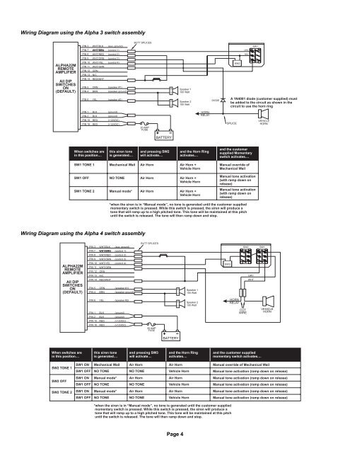
Wiring Diagram using the <strong>Alpha</strong> 3 switch assembly<br />
ALPHA<strong>22M</strong><br />
REMOTE<br />
AMPLIFIER<br />
All DIP<br />
SWITCHES<br />
ON<br />
(DEFAULT)<br />
PIN 3<br />
PIN 7<br />
WHT/BRN<br />
PIN 8 WHT/RED<br />
PIN 9 WHT/ORN<br />
PIN 10 WHT/YEL<br />
PIN 11 WHT/GRN<br />
PIN 12 GRN<br />
PIN 13 N/C<br />
PIN 14 RED/WHT<br />
PIN 5<br />
PIN 4<br />
WHT/BLK<br />
ORN<br />
BRN<br />
(aux. ground)<br />
(control 1)<br />
(control 2)<br />
(control 3)<br />
(control 4)<br />
(speaker #1)<br />
(speaker ground)<br />
BUTT SPLICES<br />
1<br />
Speaker 1<br />
100 Watt<br />
SW2<br />
GRN<br />
RED<br />
SW1<br />
PIN 6 YEL (speaker #2)<br />
Speaker 2<br />
100 Watt<br />
DIODE<br />
A 1N4001 diode (customer supplied) must<br />
be added to the circuit as shown in the<br />
circuit to use the horn ring<br />
PIN 1<br />
PIN 2<br />
PIN 15<br />
PIN 16<br />
BLK<br />
BLK<br />
RED<br />
RED<br />
(ground)<br />
(ground)<br />
(+12VDC)<br />
(+12VDC)<br />
20 AMP<br />
FUSE<br />
HORN<br />
RELAY<br />
SPLICE<br />
VEHICLE<br />
HORN<br />
BATTERY<br />
When switches are<br />
in this position....<br />
this siren tone<br />
is generated....<br />
and pressing SW2<br />
will activate....<br />
and the Horn Ring<br />
activates....<br />
and the customer<br />
supplied Momentary<br />
switch activates....<br />
SW1 TONE 1<br />
Mechanical Wail<br />
Air Horn<br />
Air Horn +<br />
Vehicle Horn<br />
Manual override of<br />
Mechanical Wail<br />
SW1 OFF<br />
NO TONE<br />
Air Horn<br />
Air Horn +<br />
Vehicle Horn<br />
Manual tone activation<br />
(with ramp down on<br />
release)<br />
SW1 TONE 2<br />
Manual mode*<br />
Air Horn<br />
Air Horn +<br />
Vehicle Horn<br />
Manual tone activation<br />
(with ramp down on<br />
release)<br />
*when the siren is in “Manual mode”, no tone is generated until the customer supplied<br />
momentary switch is pressed. While this switch is pressed, the siren will produce a<br />
tone that will ramp up to a high pitched tone. This tone will be maintained at this pitch<br />
until the switch is released. The tone will then ramp down and stop.<br />
Wiring Diagram using the <strong>Alpha</strong> 4 switch assembly<br />
ALPHA<strong>22M</strong><br />
REMOTE<br />
AMPLIFIER<br />
All DIP<br />
SWITCHES<br />
ON<br />
(DEFAULT)<br />
PIN 3<br />
PIN 7<br />
WHT/BRN<br />
PIN 8 WHT/RED<br />
PIN 9 WHT/ORN<br />
PIN 10 WHT/YEL<br />
PIN 11 WHT/GRN<br />
PIN 12 GRN<br />
PIN 13 N/C<br />
PIN 14 RED/WHT<br />
PIN 5<br />
PIN 4<br />
WHT/BLK<br />
ORN<br />
BRN<br />
(aux. ground)<br />
(control 1)<br />
(control 2)<br />
(control 3)<br />
(control 4)<br />
(speaker #1)<br />
(speaker ground)<br />
BUTT SPLICES<br />
1<br />
Speaker 1<br />
100 Watt<br />
SW3<br />
SW2<br />
GRY<br />
WHT<br />
SW1<br />
PIN 6 YEL (speaker #2)<br />
PIN 1<br />
PIN 2<br />
BLK<br />
BLK<br />
PIN 15 RED<br />
PIN 16 RED<br />
(ground)<br />
(ground)<br />
(+12VDC)<br />
(+12VDC)<br />
20 AMP<br />
FUSE<br />
Speaker 2<br />
100 Watt<br />
HORN<br />
RELAY<br />
CUT<br />
WIRE<br />
VEHICLE<br />
HORN<br />
BATTERY<br />
When switches are<br />
in this position....<br />
this siren tone<br />
is generated....<br />
and pressing SW3<br />
will activate....<br />
and the Horn Ring<br />
activates....<br />
and the customer supplied<br />
momentary switch activates....<br />
SW2 TONE 1<br />
SW2 OFF<br />
SW2 TONE 2<br />
SW1 ON<br />
SW1 OFF<br />
Mechanical Wail<br />
NO TONE<br />
Air Horn<br />
NO TONE<br />
Air Horn<br />
Vehicle Horn<br />
SW1 ON Manual mode* Air Horn<br />
Air Horn<br />
SW1 OFF NO TONE<br />
NO TONE<br />
Vehicle Horn<br />
SW1 ON Manual mode* Air Horn<br />
Air Horn<br />
SW1 OFF NO TONE<br />
NO TONE<br />
Vehicle Horn<br />
Manual override of Mechanical Wail<br />
Manual tone activation (ramp down on release)<br />
Manual tone activation (ramp down on release)<br />
Manual tone activation (ramp down on release)<br />
Manual tone activation (ramp down on release)<br />
Manual tone activation (ramp down on release)<br />
*when the siren is in “Manual mode”, no tone is generated until the customer supplied<br />
momentary switch is pressed. While this switch is pressed, the siren will produce a<br />
tone that will ramp up to a high pitched tone. This tone will be maintained at this pitch<br />
until the switch is released. The tone will then ramp down and stop.<br />
Page 4