MVL10-WR 2.4 GHz Wireless Video Link System ... - Supercircuits Inc.
MVL10-WR 2.4 GHz Wireless Video Link System ... - Supercircuits Inc.
MVL10-WR 2.4 GHz Wireless Video Link System ... - Supercircuits Inc.

You also want an ePaper? Increase the reach of your titles
YUMPU automatically turns print PDFs into web optimized ePapers that Google loves.
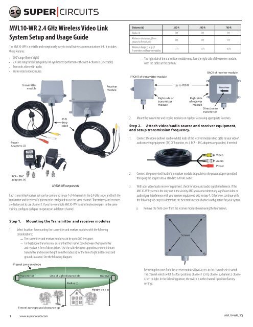
<strong>MVL10</strong>-<strong>WR</strong> <strong>2.4</strong> <strong>GHz</strong> <strong>Wireless</strong> <strong>Video</strong> <strong>Link</strong><br />
<strong>System</strong> Setup and Usage Guide<br />
The <strong>MVL10</strong>-<strong>WR</strong> is a reliable and exceptionally easy to install wireless communications link. It includes<br />
these features:<br />
• 700’ range (line of sight)<br />
• <strong>2.4</strong> <strong>GHz</strong> range broadcast quality FM-synthesized performance the with 4 channels (selectable)<br />
• Transmits video with audio<br />
• Water-resistant enclosures<br />
Distance (d) 250 ft 500 ft 700 ft<br />
Radius (r) 5 ft 7 ft 9 ft<br />
Minimum clearance (g) from<br />
ground to Fresnel zone<br />
Minimum height (r + g) of<br />
Transmitter and Receiver modules<br />
7 ft 7 ft 7 ft<br />
12 ft 14 ft 16 ft<br />
——<br />
The right side of the transmitter module must face the right side of the receiver module,<br />
with the cables at the bottom.<br />
FRONT of transmitter module<br />
BACK of receiver module<br />
Transmitter<br />
module<br />
Receiver<br />
module<br />
Up to 700 ft<br />
25 ft<br />
drop<br />
cable<br />
Right side of<br />
transmitter<br />
module<br />
Right side<br />
of receiver<br />
module<br />
Direction to<br />
transmitter<br />
2. Mount the transmitter and receive modules on rigid surfaces using appropriate fasteners.<br />
Step 2. Attach video/audio source and receiver equipment,<br />
and setup transmission frequency.<br />
Power<br />
Adapters (2)<br />
1. Connect the video (yellow) /audio (white) leads of the receiver module drop cable to your video/<br />
audio receiving equipment (TV, DVR monitor, etc.). RCA - BNC adapters are provided, if needed.<br />
<strong>Video</strong><br />
Audio<br />
Power<br />
RCA - BNC<br />
adapters (4)<br />
<strong>MVL10</strong>-<strong>WR</strong> components<br />
Each transmitter/receiver pair can be configured to use 1 of 4 channels in the <strong>2.4</strong> <strong>GHz</strong> range, and both the<br />
transmitter and receiver of a pair must be configured to use the same channel. Transmitters and receivers<br />
are factory set to use channel 1. If you have multiple <strong>MVL10</strong>-<strong>WR</strong> transmitter/receiver pairs in the same<br />
vicinity, configure each pair to operate on a different channel.<br />
2. Connect the power (red) lead of the receiver module drop cable to the power adapter provided,<br />
then plug the adapter into a standard 120 VAC outlet.<br />
3. With your video/audio receiver equipment, check for video and audio signal interference. If this<br />
<strong>MVL10</strong>-<strong>WR</strong> system is the only one in the vicinity AND you cannot detect any significant video or<br />
audio signal interference with your receiver equipment, skip to step 4. Otherwise, continue with<br />
the following sub-steps to determine the best transmission channel configuration for your system.<br />
a. Remove the front cover from the receiver module by removing the four screws.<br />
Step 1.<br />
Mounting the Transmitter and receiver modules<br />
1. Select locations for mounting the transmitter and receiver modules with the following<br />
considerations:<br />
——<br />
The transmitter and receiver modules can be up to 700 feet apart.<br />
——<br />
For best signal transmission, ensure that the Fresnel zone between the transmitter<br />
and receiver is free of obstructions. Use the table below to approximate the minimum<br />
transmitter and receiver height from the radius (r) for the line of sight distance (d) and<br />
ground clearance. See the following diagram.<br />
Screws<br />
Fresnel zone envelope<br />
Transmitter<br />
Line of sight distance (d)<br />
Radius (r)<br />
Receiver<br />
Removing the cover from the receiver module allows access to the channel select switch.<br />
The channel select switch has four positions, channel 1 (CH1), channel 2, channel 3, channel<br />
4, left to right. In the following picture, the switch is in the channel 1 position (factory<br />
setting).<br />
Height ≥ r + g<br />
Fresnel zone ground clearance (g)<br />
1 www.supercircuits.com <strong>MVL10</strong>-<strong>WR</strong>_SQ
CH1 CH2 CH3 CH4<br />
b. Pry off the channel switch cover using a small blade screwdriver.<br />
CH4 CH3<br />
CH2 CH1<br />
b. While monitoring the video and audio output of your receiver, select each channel to<br />
determine which channel is the most interference free. Set the switch to this position and<br />
record the channel number.<br />
Channel: ____________<br />
4. Connect your video and audio source equipment (camera, microphone, etc.) to the transmitter<br />
drop cable video (yellow) and audio (white) leads. RCA - BNC adapters are provided, if needed.<br />
<strong>Video</strong><br />
Audio<br />
Power<br />
5. If the receiver module is setup to use channel 1 (factory setting), connect the power (red) lead of<br />
the transmitter module drop cable to the power adapter provided, then plug the adapter into a<br />
standard 120 VAC outlet. Otherwise, don’t power on the transmitter yet, and perform the following<br />
sub-steps to set the transmission frequency to the receiver module setting.<br />
a. Remove the front cover from the transmitter module by removing the four screws.<br />
Removing the front cover allows access to the transmission channel select switches.<br />
Transmission channels 1 through 4 (CH1 .. CH4) are selected by sliding to ON the switch<br />
numbered for the channel (see the table below). Only one channel switch should be ON at<br />
any time. In the following picture, only switch 1 (for channel 1) is ON (factory default).<br />
Transmission<br />
Channel<br />
Switch positions<br />
4 3 2 1<br />
Channel 1 off off off ON<br />
Channel 2 off off ON off<br />
Channel 3 off ON off off<br />
Channel 4 ON off off off<br />
c. Set the channel select switch to ON for channel selected in the receiver module. Verify that<br />
all other channel select switches are not ON (off).<br />
d. Reinstall the transmitter channel switch cover by pressing it into place.<br />
e. Connect the power (red) lead of the transmitter module drop cable to the power adapter<br />
provided, then plug the adapter into a standard 120 VAC outlet. The <strong>MVL10</strong>-<strong>WR</strong> wireless link<br />
should now be functional.<br />
6. At the receiver module, check the quality of the video and audio received through the wireless link<br />
from your video source. If the video and/or audio signals received are low quality, do the following<br />
until an acceptable signal is provided from the receiver module:<br />
a. Verify that all video, audio, and power connections in your system are secure.<br />
Channel<br />
switches<br />
under inner<br />
cover<br />
b. Use appropriate monitoring equipment to verify that your video/audio source equipment is<br />
functioning properly.<br />
c. Recheck the orientation location of the transmitter and receiver modules to verify that the<br />
right side of the transmitter module is directly facing the right side of the receiver module,<br />
and no interfering structures exist in the Fresnel zone between them. Check for interfering<br />
signals from other sources, and take appropriate action to mitigate them.<br />
d. Change the transmission channel you are operating on. Refer to steps 3 and 5 above.<br />
7. If the front covers of the transmitter and/or receiver module(s) were removed, reattach them.<br />
Ensure that the cover seal is positioned properly (see picture below). Tighten the 4 cover screws<br />
evenly, being careful to not over-tighten them.<br />
2 www.supercircuits.com © 2011 <strong>Supercircuits</strong>, <strong>Inc</strong>. All rights reserved.
Cover seal<br />
positioned<br />
properly<br />
Inside of cover<br />
Troubleshooting<br />
Problem<br />
No video or audio<br />
Interference in video<br />
or audio<br />
Possible Solutions<br />
• Check power, video and audio cable connections.<br />
• Verify that your video source and receiver equipment is functioning properly.<br />
• Verify that the TX and RX module are powered on.<br />
• Check the RF spectrum in the area for other devices that emit high radiation,<br />
such as microwave ovens, <strong>2.4</strong> <strong>GHz</strong> wireless devices, power equipment, etc.<br />
Specifications - TX module<br />
Item<br />
Transmitting frequencies<br />
Transmit power<br />
Modulation<br />
<strong>Video</strong> input level<br />
Audio input level<br />
Antenna<br />
Power requirements<br />
Power adapter<br />
Dimensions<br />
Weight<br />
Specification<br />
<strong>2.4</strong>00 <strong>GHz</strong>, <strong>2.4</strong>27 <strong>GHz</strong>, <strong>2.4</strong>54 <strong>GHz</strong>, or <strong>2.4</strong>81 <strong>GHz</strong> (selectable)<br />
10 dBm (maximum)<br />
Frequency (FM)<br />
1 Vp-p @ 75 Ω<br />
1 Vp-p @ 600 Ω<br />
Directional<br />
300 mA @12 VDC<br />
120 VAC to 12 VDC<br />
6.0” (w) x 5.625” (h) x 2.38” (d) (15.24 cm (w) x 14.29 cm (h) x 6.05 cm (d)) without drop cable<br />
24.1 oz (686 g) with drop cable (approx.)<br />
Specifications - RX module<br />
Item<br />
Receiving frequencies<br />
Modulation<br />
Receiver sensitivity<br />
<strong>Video</strong> output level<br />
Audio output level<br />
Antenna<br />
Power consumption<br />
Power adapter<br />
Dimensions<br />
Weight<br />
Specification<br />
<strong>2.4</strong>00 <strong>GHz</strong>, <strong>2.4</strong>27 <strong>GHz</strong>, <strong>2.4</strong>54 <strong>GHz</strong>, or <strong>2.4</strong>81 <strong>GHz</strong> (selectable)<br />
Frequency (FM)<br />
80 dBm<br />
1 Vp-p @ 75 Ω<br />
1 Vp-p @ 600 Ω<br />
Omnidirectional<br />
300 mA @ 12 VDC<br />
120 VAC to 12 VDC<br />
7.19” (w) x 7.45” (h) x 4.38” (d) (18.26 cm (w) x 18.92 cm (h) x 11.13 cm (d)) without drop cable<br />
36.1 oz (1023 g) with drop cable (approx.)<br />
3 www.supercircuits.com © 2011 <strong>Supercircuits</strong>, <strong>Inc</strong>. All rights reserved.