AquaFlex® Institutional Bracket I-AB3 - Victaulic
AquaFlex® Institutional Bracket I-AB3 - Victaulic
AquaFlex® Institutional Bracket I-AB3 - Victaulic

Create successful ePaper yourself
Turn your PDF publications into a flip-book with our unique Google optimized e-Paper software.
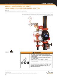
INSTALLATION INSTRUCTIONS<br />
I-<strong>AB3</strong><br />
AquaFlex ® <strong>Institutional</strong> <strong>Bracket</strong><br />
STYLE <strong>AB3</strong><br />
WARNING<br />
IMPORTANT INFORMATION<br />
• Read and understand all instructions<br />
before attempting to install any <strong>Victaulic</strong><br />
AquaFlex ® products.<br />
• Wear safety glasses, hardhat, and foot<br />
protection during installation.<br />
Failure to follow these instructions could<br />
cause improper sprinkler operation, resulting<br />
in serious personal injury and/or property<br />
damage.<br />
• <strong>Victaulic</strong> AquaFlex products must be installed according to<br />
current, applicable National Fire Protection Association (NFPA 13,<br />
13D, 13R, etc.) standards or equivalent standards for wet, dry, or<br />
preaction systems. Deviations from these standards or alterations<br />
to AquaFlex products or sprinklers will void any <strong>Victaulic</strong> warranty.<br />
In addition, installations must meet provisions of the local authority<br />
having jurisdiction and local codes, as applicable.<br />
• For minimum maintenance and inspection requirements, refer<br />
to NFPA 25 and the NFPA pamphlet that describes the care<br />
and maintenance of sprinkler systems. In addition, the authority<br />
having jurisdiction may have additional maintenance, testing, and<br />
inspection requirements that must be followed.<br />
INSTALLING THE STYLE <strong>AB3</strong> INSTITUTIONAL<br />
BRACKET ON A MASONRY WALL OR CEILING<br />
WARNING<br />
• These installation instructions are intended for an experienced,<br />
trained installer.<br />
• The user must understand the purpose of these products,<br />
c ommon industry standards for safety, and the potential<br />
consequences of improper product installation.<br />
Failure to follow these instructions could cause improper sprinkler<br />
operation, resulting in serious personal injury and/or property<br />
damage.<br />
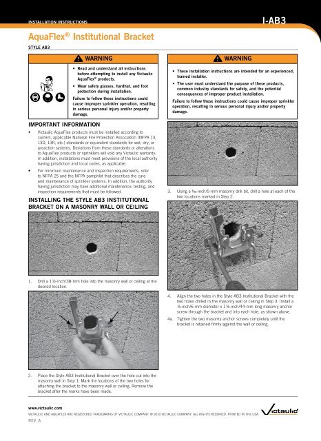
3. Using a 3/16-inch/5-mm masonry drill bit, drill a hole at each of the<br />
two locations marked in Step 2.<br />
1. Drill a 1 1/2-inch/38-mm hole into the masonry wall or ceiling at the<br />
desired location.<br />
4. Align the two holes in the Style <strong>AB3</strong> <strong>Institutional</strong> <strong>Bracket</strong> with the<br />
two holes drilled in the masonry wall or ceiling in Step 3. Install a<br />
1/4-inch/6-mm diameter x 1 3/4-inch/44-mm long masonry anchor<br />
screw through the bracket and into each hole, as shown above.<br />
4a. Tighten the two masonry anchor screws completely until the<br />
bracket is retained firmly against the wall or ceiling.<br />
2. Place the Style <strong>AB3</strong> <strong>Institutional</strong> <strong>Bracket</strong> over the hole cut into the<br />
masonry wall in Step 1. Mark the locations of the two holes for<br />
attaching the bracket to the masonry wall or ceiling. Remove the<br />
bracket after the marks have been made.<br />
www.victaulic.com<br />
VICTAULIC AND AQUAFLEX ARE REGISTERED TRADEMARKS OF VICTAULIC COMPANY. © 2010 VICTAULIC COMPANY. ALL RIGHTS RESERVED. PRINTED IN THE USA.<br />
REV_A
INSTALLATION INSTRUCTIONS<br />
I-<strong>AB3</strong><br />
AquaFlex ® <strong>Institutional</strong> <strong>Bracket</strong><br />
STYLE <strong>AB3</strong><br />
CONNECTING THE AQUAFLEX STAINLESS STEEL<br />
FLEXIBLE HOSE TO THE BRANCH LINE<br />
WARNING<br />
• The flexible stainless steel hose should not be bent or<br />
fluctuated up-and-down or side-to-side when it is pressurized<br />
for test.<br />
• The flexible stainless steel hose should not be bent within<br />
2 1/2 inches/64 mm of the connection nut at both ends.<br />
Failure to follow these instructions could cause improper sprinkler<br />
operation, resulting in serious personal injury and/or property<br />
damage.<br />
Always refer to the I-AQUAFLEX installation instructions for important<br />
information regarding stainless steel flexible hose bend characteristics,<br />
friction loss data, and other technical data. Style <strong>AB3</strong> <strong>Institutional</strong><br />
<strong>Bracket</strong>s must be installed only with AquaFlex stainless steel flexible<br />
hoses.<br />
3. Connect the nut of the flexible stainless steel hose to the sprinkler<br />
reducing nipple. DO NOT use pipe joint compound or Teflon tape<br />
on the fine threads of the sprinkler reducing nipple, since the<br />
flat gasket on the end of the flexible stainless steel hose provides<br />
the leak-proof connection. Tighten the connection to a maximum<br />
torque of 15 ft-lbs/20 N•m. NOTE: To prevent damage to the seal,<br />
DO NOT exceed the specified torque on the nut.<br />
1. Apply pipe joint compound or Teflon* tape to the NPT threads<br />
of the branch line connection nipple. NOTE: DO NOT use a<br />
combination of pipe joint compound and tape. Using a pipe<br />
wrench, tighten the branch line connection nipple into the branch<br />
line.<br />
2. Connect the nut of the flexible stainless steel hose to the branch<br />
line connection nipple, as shown above. DO NOT use pipe joint<br />
compound or Teflon tape on the threads of the branch line<br />
connection nipple, since the flat gasket on the end of the flexible<br />
stainless steel hose provides the leak-proof connection. Tighten<br />
the connection to a maximum torque of 15 ft-lbs/20 N•m. NOTE:<br />
To prevent damage to the seal, DO NOT exceed the specified<br />
torque on the nut.<br />
* Teflon is a registered trademark of the DuPont Company<br />
4. Slide the sprinkler reducing nipple into the center gate assembly<br />
and through the hole in the masonry wall or ceiling. Make sure the<br />
bends in the stainless steel flexible hose comply with requirements<br />
in the I-AQUAFLEX installation instructions.<br />
4a. Close the gate around the sprinkler reducing nipple. Swing the<br />
pivot screw into the slot on the gate, and tighten the wing nut to<br />
secure the sprinkler reducing nipple in the desired location. NOTE:<br />
The pivot screw is staked to prevent the wing nut from being<br />
backed off/removed completely.<br />
5. Apply pipe joint compound or Teflon tape to the male threads of<br />
the institutional sprinkler. Install the institutional sprinkler into the<br />
sprinkler reducing nipple by following the sprinkler manufacturer’s<br />
installation instructions.<br />
6. After installation is complete, test the system for leaks in<br />
accordance with NFPA guidelines.<br />
WARNING<br />
• Re-location of AquaFlex products MUST be performed by<br />
qualified personnel familiar with the system’s original design<br />
criteria, sprinkler listings/approvals, and state and local codes<br />
(including NFPA 13 standards).<br />
Failure to re-locate this AquaFlex product properly could affect its<br />
performance during a fire, resulting in serious personal injury and<br />
property damage.<br />
For complete contact information, visit www.victaulic.com<br />
I-<strong>AB3</strong> 6025 REV A UPDATED 02/2010 Z000<strong>AB3</strong>000<br />
VICTAULIC AND AQUAFLEX ARE REGISTERED TRADEMARKS OF VICTAULIC COMPANY. © 2010 VICTAULIC COMPANY. ALL RIGHTS RESERVED. PRINTED IN THE USA.<br />
I-<strong>AB3</strong>