

Autonomous Vehicles - KPIT
Autonomous Vehicles - KPIT
Autonomous Vehicles - KPIT

You also want an ePaper? Increase the reach of your titles
YUMPU automatically turns print PDFs into web optimized ePapers that Google loves.
Figure 3: Remote control electronics subsystems<br />
In order to prevent any false command<br />
attributable to data corruption, this frame has<br />
built in checksum error detection feature. This<br />
electronics has two separate controllers to<br />
share the task of controlling actuators i.e. the<br />
data packet containing wireless commands is<br />
fed simultaneously to both controllers. These<br />
controllers react to specific byte sequences.<br />
Figure 3 depicts all subsystems.<br />
A. Remote Ignition/Vehicle control: This<br />
subsystem automates the ignition controls in<br />
the vehicle. To crank the engine, the crank<br />
signal needs to be held logical high (~5V) and<br />
then should be brought to logical low (~0V).<br />
This was achieved by using suitable<br />
electromechanical relay with timing control<br />
provided by the embedded controller i.e. this<br />
served as a parallel ignition option in addition<br />
to normal cranking operation through turning<br />
of the key.<br />
B. Remote Throttle: This subsystem<br />
automates throttle operation using an<br />
electronic drive circuit. The vehicle<br />
implements an electric throttle whereas the<br />
operation of throttle lever generates two<br />
proportional analog electric signals. These<br />
signals are input to engine ECU within the<br />
vehicle. The remote throttle circuit<br />
proportionally generates two similar<br />
proportional analog signals using ADC in<br />
response to remote throttle command of 0 to<br />
255 steps.<br />
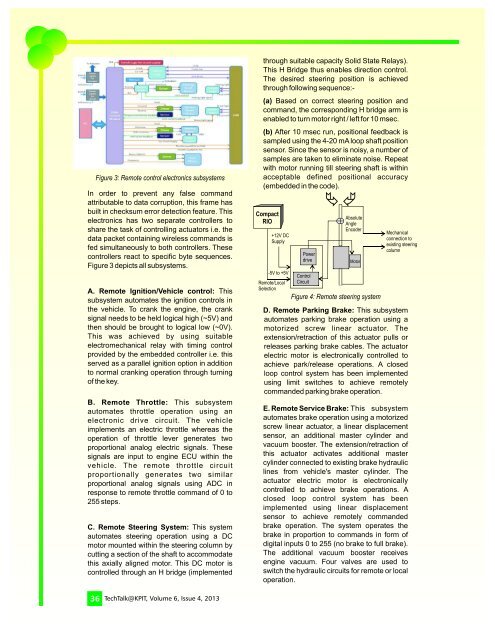
C. Remote Steering System: This system<br />
automates steering operation using a DC<br />
motor mounted within the steering column by<br />
cutting a section of the shaft to accommodate<br />
this axially aligned motor. This DC motor is<br />
controlled through an H bridge (implemented<br />
through suitable capacity Solid State Relays).<br />
This H Bridge thus enables direction control.<br />
The desired steering position is achieved<br />
through following sequence:-<br />
(a) Based on correct steering position and<br />
command, the corresponding H bridge arm is<br />
enabled to turn motor right / left for 10 msec.<br />
(b) After 10 msec run, positional feedback is<br />
sampled using the 4-20 mA loop shaft position<br />
sensor. Since the sensor is noisy, a number of<br />
samples are taken to eliminate noise. Repeat<br />
with motor running till steering shaft is within<br />
acceptable defined positional accuracy<br />
(embedded in the code).<br />
Compact<br />
RIO<br />
+12V DC<br />
Supply<br />
-5V to +5V<br />
Remote/Local<br />
Selection<br />
Power<br />
drive<br />
Control<br />
Circuit<br />
Absolute<br />
Angle<br />
Encoder<br />
Motor<br />
Figure 4: Remote steering system<br />
Mechanical<br />
connection to<br />
existing steering<br />
column<br />
D. Remote Parking Brake: This subsystem<br />
automates parking brake operation using a<br />
motorized screw linear actuator. The<br />
extension/retraction of this actuator pulls or<br />
releases parking brake cables. The actuator<br />
electric motor is electronically controlled to<br />
achieve park/release operations. A closed<br />
loop control system has been implemented<br />
using limit switches to achieve remotely<br />
commanded parking brake operation.<br />
E. Remote Service Brake: This subsystem<br />
automates brake operation using a motorized<br />
screw linear actuator, a linear displacement<br />
sensor, an additional master cylinder and<br />
vacuum booster. The extension/retraction of<br />
this actuator activates additional master<br />
cylinder connected to existing brake hydraulic<br />
lines from vehicle's master cylinder. The<br />
actuator electric motor is electronically<br />
controlled to achieve brake operations. A<br />
closed loop control system has been<br />
implemented using linear displacement<br />
sensor to achieve remotely commanded<br />
brake operation. The system operates the<br />
brake in proportion to commands in form of<br />
digital inputs 0 to 255 (no brake to full brake).<br />
The additional vacuum booster receives<br />
engine vacuum. Four valves are used to<br />
switch the hydraulic circuits for remote or local<br />
operation.<br />
36 TechTalk@<strong>KPIT</strong>, Volume 6, Issue 4, 2013