Netherlands: high-tech fastening for high-speed track ... - Hilti
Netherlands: high-tech fastening for high-speed track ... - Hilti
Netherlands: high-tech fastening for high-speed track ... - Hilti

Create successful ePaper yourself
Turn your PDF publications into a flip-book with our unique Google optimized e-Paper software.
Magazine Fall/Winter 2005<br />
Engineering<br />
Page 21<br />
Rheda 2000 slab<br />
concrete sleepers<br />
superstructure<br />
substructure<br />
outer dowels inner dowels outer dowels<br />
interface<br />
With a view to minimizing<br />
the height of construction,<br />
the slab <strong>track</strong> of the <strong>high</strong>-<strong>speed</strong> rail<br />
system under construction in the<br />
<strong>Netherlands</strong> has an exceptionally<br />
low profile. This led to use of a<br />
concrete slab sandwich design<br />
with the substructure and superstructure<br />
separated by an intermediate<br />
geotextile layer (image 1). In<br />
conventional slab <strong>track</strong> designs,<br />
transverse and longitudinal <strong>for</strong>ces<br />
are taken up by the walls of the<br />
trough <strong>for</strong>med by the substructure.<br />
In this particular case, however, the<br />
<strong>for</strong>ces involved were required to<br />
flow between the slabs through a<br />
system of connectors. The Infra<strong>speed</strong><br />
Consortium there<strong>for</strong>e commissioned<br />
a number of companies<br />
to propose, design and test a system<br />
of connectors suitable <strong>for</strong> the<br />
task. The solution put <strong>for</strong>ward by<br />
<strong>Hilti</strong> was subsequently selected <strong>for</strong><br />
use in the construction of this<br />
stretch of <strong>high</strong>-<strong>speed</strong> <strong>track</strong>.<br />
High loads in a corrosive<br />
environment<br />
The primary requirement to be fulfilled<br />
by the Infra<strong>speed</strong> system –<br />
allowance <strong>for</strong> longitudinal movement<br />
between the slabs as a result<br />
of deflection, shrinkage or temperature<br />
differences – resulted in a<br />
concept comprising fixed inner<br />
dowels and displaceable outer<br />
dowels. These must be capable of<br />
taking up not only the <strong>high</strong> dynamic<br />
loads of normal railway operation,<br />
but also the static loads<br />
that may occur in extreme situations<br />
such as derailment. In order<br />
to ensure that loads occurring in<br />
the system do not exceed the permissible<br />
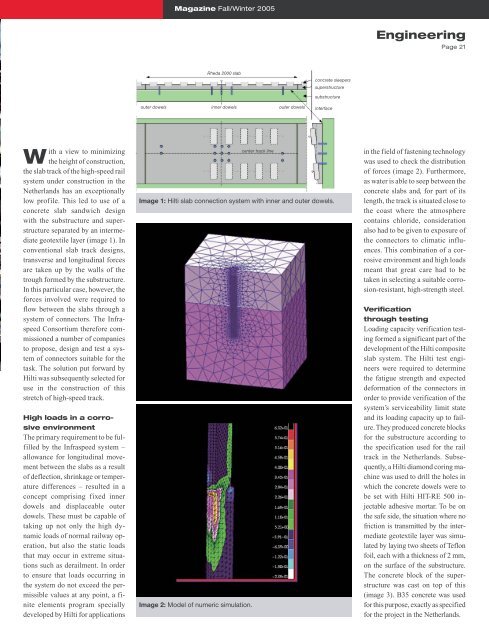
values at any point, a finite<br />
elements program specially<br />
developed by <strong>Hilti</strong> <strong>for</strong> applications<br />
Image 1: <strong>Hilti</strong> slab connection system with inner and outer dowels.<br />
Image 2: Model of numeric simulation.<br />
center <strong>track</strong> line<br />
in the field of <strong>fastening</strong> <strong>tech</strong>nology<br />
was used to check the distribution<br />
of <strong>for</strong>ces (image 2). Furthermore,<br />
as water is able to seep between the<br />
concrete slabs and, <strong>for</strong> part of its<br />
length, the <strong>track</strong> is situated close to<br />
the coast where the atmosphere<br />
contains chloride, consideration<br />
also had to be given to exposure of<br />
the connectors to climatic influences.<br />
This combination of a corrosive<br />
environment and <strong>high</strong> loads<br />
meant that great care had to be<br />
taken in selecting a suitable corrosion-resistant,<br />
<strong>high</strong>-strength steel.<br />
Verification<br />
through testing<br />
Loading capacity verification testing<br />
<strong>for</strong>med a significant part of the<br />
development of the <strong>Hilti</strong> composite<br />
slab system. The <strong>Hilti</strong> test engineers<br />
were required to determine<br />
the fatigue strength and expected<br />
de<strong>for</strong>mation of the connectors in<br />
order to provide verification of the<br />
system’s serviceability limit state<br />
and its loading capacity up to failure.<br />
They produced concrete blocks<br />
<strong>for</strong> the substructure according to<br />
the specification used <strong>for</strong> the rail<br />
<strong>track</strong> in the <strong>Netherlands</strong>. Subsequently,<br />
a <strong>Hilti</strong> diamond coring machine<br />
was used to drill the holes in<br />
which the concrete dowels were to<br />
be set with <strong>Hilti</strong> HIT-RE 500 injectable<br />
adhesive mortar. To be on<br />
the safe side, the situation where no<br />
friction is transmitted by the intermediate<br />
geotextile layer was simulated<br />
by laying two sheets of Teflon<br />
foil, each with a thickness of 2 mm,<br />
on the surface of the substructure.<br />
The concrete block of the superstructure<br />
was cast on top of this<br />
(image 3). B35 concrete was used<br />
<strong>for</strong> this purpose, exactly as specified<br />
<strong>for</strong> the project in the <strong>Netherlands</strong>.