INSTRUCTION - PROXIMITY backbox reader - IP Way
INSTRUCTION - PROXIMITY backbox reader - IP Way
INSTRUCTION - PROXIMITY backbox reader - IP Way

You also want an ePaper? Increase the reach of your titles
YUMPU automatically turns print PDFs into web optimized ePapers that Google loves.
17/07/2007<br />
Ins-184 <strong>PROXIMITY</strong> <strong>backbox</strong> <strong>reader</strong><br />
Technical Support<br />
+44(0)845 8381716 support@paxton.co.uk<br />
Technical help is available:<br />
Monday - Friday from 07:00 - 01:00 (GMT)<br />
Saturday from 09:00 - 13:00 (GMT)<br />
Further documentation on all Paxton products can be found on our web site - http://www.paxton.co.uk/<br />
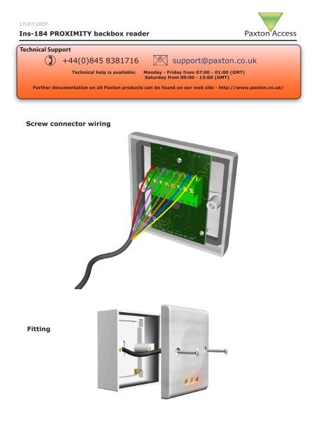
Screw connector wiring<br />
Fitting
Wiring<br />
Red<br />
Brown<br />
Orange<br />
Green<br />
Yellow<br />
Blue<br />
Mauve<br />
Black/White<br />
Brown<br />
Yellow<br />
Orange<br />
Red 12v dc<br />
Brown<br />
Orange<br />
Green<br />
Yellow<br />
Blue<br />
Mauve<br />
Black/White<br />
Brown<br />
Yellow<br />
Orange<br />
Reader 1<br />
Keypad 1<br />
Screen or spare cores<br />
from network cable<br />
1<br />
2<br />
3<br />
4<br />
White/Green<br />
Green<br />
White/Orange<br />
Orange<br />
Keypad 2<br />
CAUTION: for 12v d.c. <strong>reader</strong>s only. For<br />
correct connection of old 5v <strong>reader</strong>s, refer to<br />
instructions.<br />
Relay 1<br />
Network<br />
Tx<br />
CAT5 cable coding<br />
Rx<br />
Relay 2<br />
z-1440<br />
Exit<br />
Contact<br />
Test ID: 012345678901<br />
Reader 2<br />
Tamper<br />
Serial number<br />
241821<br />
PSU<br />
3 2 4 8 9 8 0 0 0 0 0 4<br />
OK<br />
5v<br />
12v<br />
Relay 2 Relay 1 Power<br />
+12v<br />
0v<br />
N.C.<br />
N.O.<br />
Com<br />
N.C.<br />
N.O.<br />
Com<br />
Alarm Output<br />
0v<br />
Contact<br />
0v<br />
Inputs<br />
Exit<br />
0v<br />
Tamper<br />
PSU<br />
Red 12V<br />
Brown<br />
Orange<br />
Green<br />
Yellow<br />
Blue<br />
Mauve<br />
Card <strong>reader</strong> or keypad<br />
Switch2<br />
Control<br />
unit<br />
Power<br />
Door relay<br />
Alarm<br />
Bell<br />
12v<br />
0v<br />
N.C.<br />
N.O.<br />
Com<br />
Black<br />
Contact<br />
Exit<br />
Inputs<br />
CAUTION: For 12V d.c. <strong>reader</strong>s only.<br />
For correct connection of old <strong>reader</strong>s,<br />
refer to instructions.<br />
Cable extensions<br />
Readers can be extended using Beldon CR9540 10-core overall screened cable. The maximum cable length is<br />
100 metres.<br />
Red<br />
Brown<br />
Orange<br />
Green<br />
Yellow<br />
Blue<br />
Mauve<br />
Black/White<br />
Brown<br />
Yellow<br />
Orange<br />
Red<br />
Brown<br />
Orange<br />
Green<br />
Yellow<br />
Blue<br />
Mauve<br />
Black/White<br />
Brown<br />
Yellow<br />
Orange<br />
Reader 1<br />
Keypad 1<br />
Screen or spare cores<br />
from network cable<br />
Keypad 2<br />
z-1440<br />
Test ID: 012345678901<br />
Reader 2<br />
Serial number<br />
241821<br />
3 2 4 8 9 8 0 0 0 0 0 4<br />
Relay 2 Relay 1 Power<br />
+12v<br />
0v<br />
N.C.<br />
N.O.<br />
Com<br />
N.C.<br />
N.O.<br />
Com<br />
Alarm Output<br />
0v<br />
Contact<br />
0v<br />
1<br />
2<br />
3<br />
4<br />
White/Green<br />
Green<br />
White/Orange<br />
Orange<br />
Relay 1<br />
Network<br />
Tx<br />
CAT5 cable coding<br />
Rx<br />
Relay 2<br />
Exit<br />
Contact<br />
Tamper<br />
PSU<br />
OK<br />
5v<br />
12v<br />
Inputs<br />
Exit<br />
0v<br />
Tamper<br />
PSU<br />
White Labelled control units only provide 5v at<br />
the Red terminal. The red power wire for the<br />
<strong>reader</strong> should be connected directly to the 12v<br />
PCB supply terminal - as per diagram.<br />
Red<br />
Brown<br />
Orange<br />
Green<br />
Yellow<br />
Blue<br />
Mauve<br />
Black<br />
Contact<br />
Exit<br />
Inputs<br />
Card <strong>reader</strong> or keypad<br />
Switch2<br />
Control<br />
unit<br />
Power<br />
Door relay<br />
Alarm<br />
Bell<br />
12v<br />
0v<br />
N.C.<br />
N.O.<br />
Com
Frequently asked questions<br />
Here is the list of topics about this product that receive the most technical support enquiries. We<br />
list them here to help you speed up the installation and trouble shooting process.<br />
1 - Readers/Keypads not working<br />
. Software settings - Confirm that the settings of the <strong>reader</strong> or keypad are correct.<br />
. Connections - Check the wiring and integrity of <strong>reader</strong>/keypad terminal connections.<br />
. To confirm that an extended <strong>reader</strong> cable is not at fault, wire the <strong>reader</strong> direct into the <strong>reader</strong> port. If the <strong>reader</strong><br />
works, this indicates a problem with the cable.<br />
. Supply voltage - confirm that the <strong>reader</strong> has sufficient voltage.<br />
. User token - Check that the user token used for testing the <strong>reader</strong> is operational.<br />
. Interference - Confirm whether the <strong>reader</strong> works when tested ‘in hand’ and not mounted on the wall. Ensure that<br />
<strong>reader</strong>s are not mounted back to back or there is not interference from other RF devices.<br />
2 - Readers / Keypads - Extending cable<br />
. Only Belden CR9538 /9540 can be used for cable extensions. CR9538 is 8 core for up to 25m, CR9540 10 core<br />
for 25-100m (maximum extension). When using CR9540, the two additional cores should be used to double up for<br />
power.<br />
3 - Net2 - What to do if a user has no access<br />
. Check the <strong>reader</strong> LEDs when a card is shown:<br />
. No LEDs - the <strong>reader</strong> has no power.<br />
. No change in display - try the card on a known working <strong>reader</strong>s. If there is still no response, replace the card.<br />
. Green LED flashing when a card is presented, check the Relay 1 LED to check activity and the wiring to the lock.<br />
. Red LED is flashing when a card is presented, check the validity of the user at the PC.<br />
. - Check user’s access level and ensure they have access by clicking on Current Validity.<br />
. - Check the ‘Valid Until’ date and confirm this has not expired.<br />
. Reinstate the ACU from the doors screen. Select the ACU’s you wish to reinstate and then click OK.<br />
4 - Switch2 - Adding an additional card pack<br />
. You need to be in possession of the original enrolment card. Present the original enrolment card to the <strong>reader</strong><br />
and the Amber LED will flash, Green & Red LEDs will be off, then present the Enrolment card from the new card<br />
pack; the <strong>reader</strong> will beep and all LEDS will be lit. The additional cards will now be valid. Repeat this with each<br />
<strong>reader</strong> and with any additional card packs. Any valid enrolment card can be used to add further packs. This is the<br />
same for enrolling function card packs onto a system.<br />
5 - Switch2 - How to reset the controller<br />
. Disconnect the power and remove the wires from the Green and Mauve terminals<br />
. Insert a wire link between the Green and Mauve terminals<br />
. Reconnect the power (the unit will bleep 4 times)<br />
. Disconnect the power and remove the link wire, reconnect the Green and Mauve wires<br />
. Reconnect the power (the unit will bleep 3 times per second). The unit is ready to be enrolled.<br />
Suitability<br />
Security sensitive doors<br />
Mounted on metal surface<br />
Wet environments<br />
Readers mounted together<br />
300mm<br />
between<br />
<strong>reader</strong>s
Specifications<br />
Min<br />
Max<br />
Environment<br />
Operating temperatures - all items<br />
-20 °C +55 °C<br />
Waterproof<br />
Cable length<br />
NO<br />
None included<br />
Electrical<br />
Min<br />
Max<br />
Voltage<br />
8v DC 14v DC<br />
Current<br />
100 mA 300 mA<br />
Carrier frequency<br />
Clock and data bit period<br />
125 kHz<br />
600 µs<br />
Dimensions<br />
Width Height Depth<br />
86 mm 86 mm 16 mm<br />
Read Range Token Keyfob Hands Free Token<br />
100 mm 60 mm Not Compatible<br />
The declaration of conformity may be<br />
consulted at - http://paxton.info/596<br />
DE Paxton Access Ltd erklärt, daß diese Anlage den grundlegenden Anforderungen undanderen relevanten Bestimmungen der Direktive 1999/5/EC<br />
entspricht. Die Anlage ist zurVerwendung in allen EG- und EFTA-Mitgliedsstaaten bestimmt.<br />
DK Paxton Access Ltd erklærer, at dette udstyr er i overensstemmelse med vigtige krav ogandre relevante provisioner i Direktiv 1999/5/EC.<br />
Udstyret er beregnet til brug i alle EU- ogEFTA-medlemslande.<br />
EN Paxton Access Ltd hereby declares that this product is in conformity with all the essential requirements of the Directive 1999/5/EC. This<br />
equipment is intended for use in all the EU and EFTA countries and all other countries worldwide.<br />
ES Paxton Access Ltd declara que este equipo cumple con los requisitos esenciales y otrasdisposiciones pertinentes de la Directiva 1999/5/EC. El<br />
equipo está destinado para su uso entoda la UE y estados miembros de EFTA.<br />
FI Paxton Access Ltd takaa, että tämä laite on 1999/5/EC-direktiivin olennaistenvaatimusten ja muiden lausekkeiden mukainen. Laite on tarkoitettu<br />
käytettäväksi kaikissa EUjaEFTA-jäsenmaissa.<br />
FR Paxton Access Ltd déclare que cet équipement répond aux exigences essentielles etautres dispositions pertinentes de la directive 1999/5/EC.<br />
Cet équipement est prévu pourl utilisation dans tous les états membres de l UE et de l AELE.<br />
GR Η Paxton Access Ltd προβαίνει στην ανακοίνωση ότι αυτά τα µ ηχανή µ ατα έχουν τιςβασικές απαιτού µ ενες προδιαγραφές και υπόκεινται στις<br />
υπόλοιπες σχετικές διατάξεις τηςΟδηγητικής 1999/5/EC. Προορίζονται δε για χρήση σε όλες τις χώρες - µ έλη της ΕΕ και τηςEFTA (Ευρωπαϊκής<br />
Ένωσης Προώθησης Ε µ πορικών Συναλλαγών ).<br />
IC Paxton Access Ltd lýsir hér með yfir að þetta tæki uppfyllir grunnkröfur og tengd ákvæðiESB tilskipunar nr. 1999/5/EC. Tækið er ætlað til<br />
notkunar á Evrópska efnahagssvæðinu og íEFTA löndunum.<br />
IT La Paxton Access Ltd certifica che la presente apparecchiatura è conforme ai requisiti dilegge stabiliti nella direttiva 1999/5/EC. Il suo utilizzo<br />
dovrà avvenire in tutti i Paesi membri UEed EFTA.<br />
NL Paxton Access Ltd verklaart, dat deze uitrusting in overeenstemming is met deessentiële vereisten en andere relevante bepalingen van Richtlijn<br />
1999/5/EC. De uitrusting isbedoeld voor gebruik in alle EU en EFTA lidstaten.<br />
NO Paxton Access Ltd erklærer herved at dette utstyret oppfyller de vesentligste krav ogrelevante bestemmelser i direktiv 1999/5/EF om radio- og<br />
teleterminalutstyr. Utstyret erberegnet på bruk i alle medlemsland i EU og EFTA.<br />
PT A Paxton Access Ltd declara que este equipamento está de acordo com os requisitosbásicos e outras provisões relevantes da Directiva 1999/5/<br />
EC. Este equipamento destina-se ao uso em todos os estados-membros da União Europeia e da EFTA.<br />
SE: Paxton Access Ltd förklarar att denna utrustning överensstämmer med de väsentliga krav och regler som finns i direktivet 1999/5/EG.<br />
Utrustningen är avsedd att användas i alla medlemsstater i EU och EFTA.