

Development of a design procedure for timber concrete composite ...
Development of a design procedure for timber concrete composite ...
Development of a design procedure for timber concrete composite ...

Create successful ePaper yourself
Turn your PDF publications into a flip-book with our unique Google optimized e-Paper software.
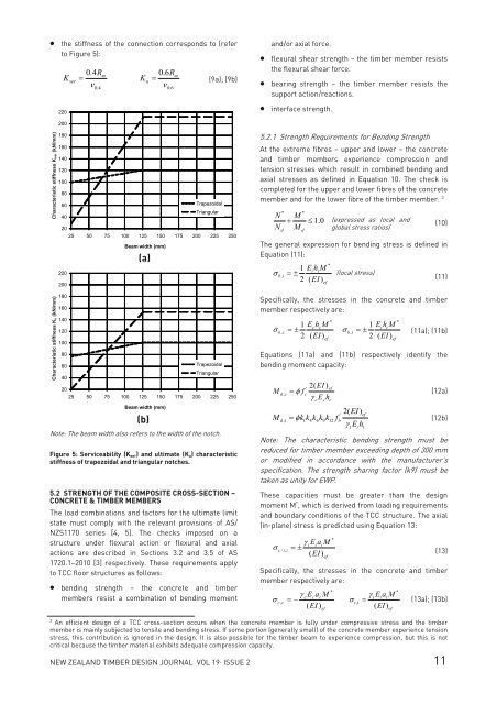
• the stiffness <strong>of</strong> the connection corresponds to (refer<br />
to Figure 5):<br />
K<br />
220<br />
ser<br />
0.4R<br />
= m<br />
ν<br />
0.4<br />
K<br />
u<br />
0.6R<br />
= m<br />
(9a); (9b)<br />
ν<br />
0.6<br />
and/or axial <strong>for</strong>ce.<br />
• flexural shear strength – the <strong>timber</strong> member resists<br />
the flexural shear <strong>for</strong>ce.<br />
• bearing strength – the <strong>timber</strong> member resists the<br />
support action/reactions.<br />
• interface strength.<br />
200<br />
180<br />
)<br />
m<br />
160<br />
/m<br />
N<br />
(k<br />
140<br />
Characteristic stiffness Kser (kN/mm)<br />
K ser<br />
s<br />
e<br />
tifn<br />
s<br />
tic<br />
ris<br />
te<br />
c<br />
ra<br />
a<br />
h<br />
C<br />
Characteristic stiffness Ku (kN/mm)<br />
)<br />
m<br />
tifn<br />
s<br />
tic<br />
ris<br />
te<br />
c<br />
ra<br />
a<br />
h<br />
C<br />
120<br />
100<br />
80<br />
60<br />
40<br />
20<br />
220<br />
200<br />
180<br />
160<br />
/m<br />
N<br />
(k<br />
140<br />
K u<br />
s<br />
120<br />
e<br />
100<br />
80<br />
60<br />
40<br />
20<br />
25 50 75 100 125 150 175 200 225 250<br />
Beam width (mm)<br />
(a)<br />
Trapezoidal<br />
Triangular<br />
25 50 75 100 125 150 175 200 225 250<br />
Beam width (mm)<br />
(b)<br />
Trapezoidal<br />
Triangular<br />
Note: The beam width also refers to the width <strong>of</strong> the notch.<br />
Figure 5: Serviceability (K ser) and ultimate (K u) characteristic<br />
stiffness <strong>of</strong> trapezoidal and triangular notches.<br />
5.2 STRENGTH OF THE COMPOSITE CROSS-SECTION –<br />
CONCRETE & TIMBER MEMBERS<br />
The load combinations and factors <strong>for</strong> the ultimate limit<br />
state must comply with the relevant provisions <strong>of</strong> AS/<br />
NZS1170 series [4, 5]. The checks imposed on a<br />
structure under flexural action or flexural and axial<br />
actions are described in Sections 3.2 and 3.5 <strong>of</strong> AS<br />
1720.1–2010 [3] respectively. These requirements apply<br />
to TCC floor structures as follows:<br />
• bending strength – the <strong>concrete</strong> and <strong>timber</strong><br />
members resist a combination <strong>of</strong> bending moment<br />
5.2.1 Strength Requirements <strong>for</strong> Bending Strength<br />
At the extreme fibres – upper and lower – the <strong>concrete</strong><br />
and <strong>timber</strong> members experience compression and<br />
tension stresses which result in combined bending and<br />
axial stresses as defined in Equation 10. The check is<br />
completed <strong>for</strong> the upper and lower fibres <strong>of</strong> the <strong>concrete</strong><br />
member and <strong>for</strong> the lower fibre <strong>of</strong> the <strong>timber</strong> member. 3<br />
N<br />
N<br />
M<br />
+ ≤ 1.0 (expressed as local and<br />
M global stress ratios)<br />
* *<br />
d<br />
d<br />
(10)<br />
The general expression <strong>for</strong> bending stress is defined in<br />
Equation (11):<br />
*<br />
1 EihM<br />
i<br />
σ<br />
bi ,<br />
=±<br />
(local stress)<br />
2 ( EI )<br />
(11)<br />
Specifically, the stresses in the <strong>concrete</strong> and <strong>timber</strong><br />
member respectively are:<br />
*<br />
*<br />
1 EchM<br />
c<br />
1 EthM<br />
t<br />
σ<br />
bc ,<br />
=±<br />
σ<br />
bt ,<br />
=± (11a); (11b)<br />
2 ( EI)<br />
2 ( EI)<br />
Equations (11a) and (11b) respectively identify the<br />
bending moment capacity:<br />
M<br />
dc ,<br />
2( EI )<br />
' ef<br />
Mdt<br />
,<br />
= φk1k4k6k9k12<br />
fb<br />
(12b)<br />
γ E h<br />
t t t<br />
Note: The characteristic bending strength must be<br />
reduced <strong>for</strong> <strong>timber</strong> member exceeding depth <strong>of</strong> 300 mm<br />
or modified in accordance with the manufacturer’s<br />
specification. The strength sharing factor (k9) must be<br />
taken as unity <strong>for</strong> EWP.<br />
These capacities must be greater than the <strong>design</strong><br />
moment M * , which is derived from loading requirements<br />
and boundary conditions <strong>of</strong> the TCC structure. The axial<br />
(in-plane) stress is predicted using Equation 13:<br />
γ<br />
iEiaM<br />
i<br />
σ<br />
c/ t,<br />
i=±<br />
( EI)<br />
ef<br />
*<br />
(13)<br />
Specifically, the stresses in the <strong>concrete</strong> and <strong>timber</strong><br />
member respectively are:<br />
*<br />
*<br />
γ<br />
cEcaM<br />
c<br />
γ<br />
tEtaM<br />
t<br />
σ<br />
cc ,<br />
=−<br />
σ<br />
tt ,<br />
= (13a); (13b)<br />
( EI)<br />
( EI)<br />
ef<br />
ef<br />
ef<br />
2( EI) '<br />
= φ f<br />
ef<br />
c<br />
(12a)<br />
γ Eh<br />
c c c<br />
ef<br />
ef<br />
3<br />
An efficient <strong>design</strong> <strong>of</strong> a TCC cross-section occurs when the <strong>concrete</strong> member is fully under compressive stress and the <strong>timber</strong><br />
member is mainly subjected to tensile and bending stress. If some portion (generally small) <strong>of</strong> the <strong>concrete</strong> member experience tension<br />
stress, this contribution is ignored in the <strong>design</strong>. It is also possible <strong>for</strong> the <strong>timber</strong> beam to experience compression, but this is not<br />
critical because the <strong>timber</strong> material exhibits adequate compression capacity.<br />
NEW ZEALAND TIMBER DESIGN JOURNAL VOL 19· ISSUE 2 11


