Maintenance Guide - Sloan Valve Company
Maintenance Guide - Sloan Valve Company
Maintenance Guide - Sloan Valve Company

Create successful ePaper yourself
Turn your PDF publications into a flip-book with our unique Google optimized e-Paper software.
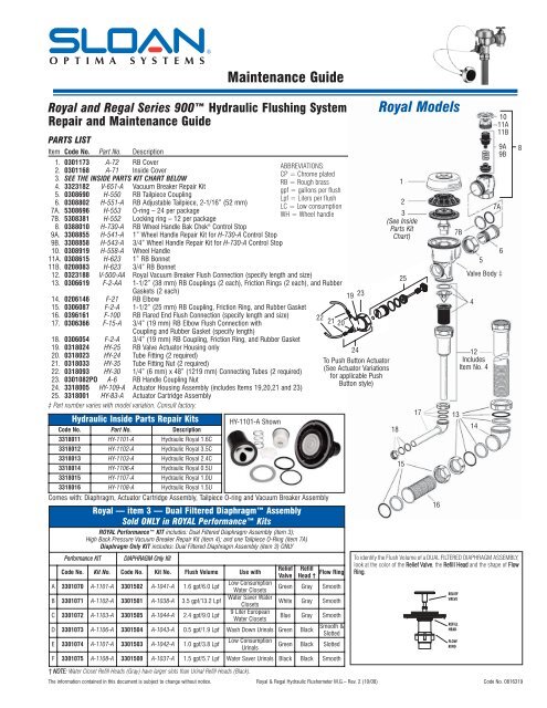
Royal and Regal Series 900 Hydraulic Flushing System<br />
Repair and <strong>Maintenance</strong> <strong>Guide</strong><br />
PARTS LIST<br />
Item Code No. Part No. Description<br />
<strong>Maintenance</strong> <strong>Guide</strong><br />
1. 0301173 A-72 RB Cover<br />
2. 0301168 A-71 Inside Cover<br />
3. SEE THE INSIDE PARTS KIT CHART BELOW<br />
4. 3323182 V-651-A Vacuum Breaker Repair Kit<br />
5. 0308690 H-550 RB Tailpiece Coupling<br />
6. 0308802 H-551-A RB Adjustable Tailpiece, 2-1/16” (52 mm)<br />
7A. 5308696 H-553 O-ring – 24 per package<br />
7B. 5308381 H-552 Locking ring – 12 per package<br />
8. 0388010 H-730-A RB Wheel Handle Bak Chek ® Control Stop<br />
9A. 3308855 H-541-A 1” Wheel Handle Repair Kit for H-730-A Control Stop<br />
9B. 3308858 H-543-A 3/4” Wheel Handle Repair Kit for H-730-A Control Stop<br />
10. 0308919 H-558-A Wheel Handle<br />
11A. 0308615 H-623 1” RB Bonnet<br />
11B. 0208083 H-623 3/4” RB Bonnet<br />
12. 0323188 V-500-AA Royal Vacuum Breaker Flush Connection (specify length and size)<br />
13. 0306619 F-2-AA 1-1/2” (38 mm) RB Couplings (2 each), Friction Rings (2 each), and Rubber<br />
Gaskets (2 each)<br />
14. 0206146 F-21 RB Elbow<br />
15. 0306087 F-2-A 1-1/2” (25 mm) RB Coupling, Friction Ring, and Rubber Gasket<br />
16. 0396161 F-100 RB Flared End Flush Connection (specify length and size)<br />
17. 0306366 F-15-A 3/4” (19 mm) RB Elbow Flush Connection with<br />
Coupling and Rubber Gasket (specify length)<br />
18. 0306054 F-2-A 3/4” (19 mm) RB Coupling, Friction Ring, and Rubber Gasket<br />
19. 0318024 HY-25 RB <strong>Valve</strong> Actuator Housing only<br />
20. 0318023 HY-24 Tube Fitting (2 required)<br />
21. 0318033 HY-35 Tube Fitting Nut (2 required)<br />
22. 0318093 HY-30 1/4” (6 mm) x 48” (1219 mm) Connecting Tubes (2 required)<br />
23. 0301082PO A-6 RB Handle Coupling Nut<br />
24. 3318005 HY-109-A Actuator Housing Assembly (includes Items 19,20,21 and 23)<br />
25. 3318001 HY-83-A Actuator Cartridge Assembly<br />
‡ Part number varies with model variation. Consult factory.<br />
Hydraulic Inside Parts Repair Kits<br />
Code No. Part No. Description<br />
3318011 HY-1101-A Hydraulic Royal 1.6C<br />
3318012 HY-1102-A Hydraulic Royal 3.5C<br />
3318013 HY-1103-A Hydraulic Royal 2.4C<br />
3318014 HY-1106-A Hydraulic Royal 0.5U<br />
3318015 HY-1107-A Hydraulic Royal 1.0U<br />
3318016 HY-1108-A Hydraulic Royal 1.5U<br />
Comes with: Diaphragm, Actuator Cartridge Assembly, Tailpiece O-ring and Vacuum Breaker Assembly<br />
Royal — item 3 — Dual Filtered Diaphragm Assembly<br />
Sold ONLY in ROYAL Performance Kits<br />
Performance KIT<br />
ROYAL Performance KIT includes: Dual Filtered Diaphragm Assembly (item 3);<br />
High Back Pressure Vacuum Breaker Repair Kit (item 4); and one Tailpiece O-Ring (item 7A)<br />
Diaphragm Only KIT includes: Dual Filtered Diaphragm Assembly (item 3) ONLY<br />
DIAPHRAGM Only Kit<br />
ABBREVIATIONS:<br />
CP = Chrome plated<br />
RB = Rough brass<br />
1<br />
gpf = gallons per flush<br />
Lpf = Liters per flush<br />
2<br />
LC = Low consumption<br />
WH = Wheel handle 3<br />
22<br />
21 20<br />
Code No. Kit No. Code No. Kit No. Flush Volume Use with<br />
Relief Refill<br />
Flow Ring<br />
<strong>Valve</strong> Head †<br />
A 3301070 A-1101-A 3301502 A-1041-A 1.6 gpf/6.0 Lpf<br />
Low Consumption<br />
Water Closets<br />
Green Gray Smooth<br />
B 3301071 A-1102-A 3301501 A-1038-A 3.5 gpf/13.2 Lpf<br />
Water Saver Water<br />
Closets<br />
White Gray Smooth<br />
C 3301072 A-1103-A 3301505 A-1044-A 2.4 gpf/9.0 Lpf<br />
9 Liter European<br />
Water Closets<br />
Blue Gray Smooth<br />
D 3301073 A-1106-A 3301504 A-1043-A 0.5 gpf/1.9 Lpf Wash Down Urinals Green Black<br />
E 3301074 A-1107-A 3301503 A-1042-A 1.0 gpf/3.8 Lpf<br />
Low Consumption<br />
Urinals<br />
The information contained in this document is subject to change without notice. Royal & Regal Hydraulic Flushometer M.G. – Rev. 2 (10/08) Code No. 0816319<br />
19 23<br />
24<br />
To Push Button Actuator<br />
(See Actuator Variations<br />
for applicable Push<br />
Button style)<br />
Smooth &<br />
Slotted<br />
Green Black Slotted<br />
F 3301075 A-1108-A 3301500 A-1037-A 1.5 gpf/5.7 Lpf Water Saver Urinals Black Black Smooth<br />
† NOTE: Water Closet Refill Heads (Gray) have larger slots than Urinal Refill Heads (Black).<br />
HY-1101-A Shown<br />
Royal Models<br />
(See Inside<br />
Parts Kit<br />
Chart)<br />
18<br />
25<br />
15<br />
17<br />
16<br />
7B<br />
13<br />
<strong>Valve</strong> Body ‡<br />
4<br />
12<br />
Includes<br />
Item No. 4<br />
14<br />
5<br />
10<br />
11A<br />
11B<br />
7A<br />
9A<br />
9B<br />
To identify the Flush Volume of a DUAL FILTERED DIAPHRAGM ASSEMBLY,<br />
look at the color of the Relief <strong>Valve</strong>, the Refill Head and the shape of Flow<br />
Ring.<br />
6<br />
8
Royal & Regal Series 900 Hydraulic<br />
Flushing System Repair and <strong>Maintenance</strong><br />
<strong>Guide</strong><br />
PARTS LIST<br />
Item Code No. Part No. Description<br />
1. 0301173 A-72 RB Cover<br />
2. 0301168 A-71 Inside Cover<br />
3. SEE THE INSIDE PARTS KIT CHART BELOW<br />
4. 3323182 V-651-A Vacuum Breaker Repair Kit<br />
5. 0308690 H-550 RB Tailpiece Coupling<br />
6. 0308802 H-551-A RB Adjustable Tailpiece, 2-1/16” (52 mm)<br />
7A. 5308696 H-553 O-ring – 24 per package<br />
7B. 5308381 H-552 Locking ring – 12 per package<br />
8. 0388010 H-730-A RB Wheel Handle Bak Chek ® Control Stop<br />
9A. 3308855 H-541-A 1” Wheel Handle Repair Kit for H-730-A Control<br />
Stop<br />
9B. 3308858 H-543-A 3/4” Wheel Handle Repair Kit for H-730-A Control<br />
Stop<br />
10. 0308919 H-558-A Wheel Handle<br />
11A. 0308615 H-623 1” RB Bonnet<br />
11B. 0208083 H-623 3/4” RB Bonnet<br />
12. 0323188 V-500-AA Royal Vacuum Breaker Flush Connection<br />
(specify length and size)<br />
13. 0306619 F-2-AA 1-1/2” (38 mm) RB Couplings (2 each), Friction<br />
Rings (2 each), and Rubber Gaskets (2 each)<br />
14. 0206146 F-21 RB Elbow<br />
15. 0306087 F-2-A 1-1/2” (25 mm) RB Coupling, Friction Ring, and 22<br />
Rubber Gasket<br />
16. 0396161 F-100 RB Flared End Flush Connection<br />
(specify length and size)<br />
17. 0306366 F-15-A 3/4” (19 mm) RB Elbow Flush Connection with<br />
Coupling and Rubber Gasket (specify length)<br />
18. 0306054 F-2-A 3/4” (19 mm) RB Coupling, Friction Ring, and<br />
Rubber Gasket<br />
19. 0318024 HY-25 RB <strong>Valve</strong> Actuator Housing only<br />
20. 0318023 HY-24 Tube Fitting (2 required)<br />
21. 0318033 HY-35 Tube Fitting Nut (2 required)<br />
22. 0318093 HY-30 1/4” (6 mm) x 48” (1219 mm) Connecting Tubes<br />
(2 required)<br />
23. 0301082PO A-6 RB Handle Coupling Nut<br />
24. 3318005 HY-109-A Actuator Housing Assembly (includes Items<br />
19,20,21 & 23)<br />
25. 3318001 HY-83-A Actuator Cartridge Assembly<br />
21<br />
20<br />
19 23<br />
24<br />
To Push Button Actuator<br />
(See Actuator Variations for<br />
applicable Push Button style)<br />
Regal Models<br />
1<br />
2<br />
3<br />
(See<br />
Inside Parts<br />
Kit Chart)<br />
25<br />
17<br />
13<br />
7B<br />
<strong>Valve</strong> Body ‡<br />
4<br />
7A<br />
5<br />
12<br />
Includes<br />
Item No. 4<br />
10<br />
11A<br />
11B<br />
9A<br />
9B<br />
6<br />
8<br />
ABBREVIATIONS:<br />
CP = Chrome plated<br />
RB = Rough brass<br />
gpf = gallons per flush<br />
Lpf = Liters per flush<br />
LC = Low consumption<br />
WH = Wheel handle<br />
18<br />
15<br />
14<br />
16<br />
‡ Part number varies with model variation. Consult factory.<br />
2
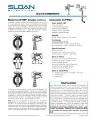
PUSH BUTTON ACTUATOR VARIATIONS<br />
HY-49-A (0318049)<br />
METAL PARTITION PUSH BUTTON<br />
HY-72-A1 (0318072)<br />
SIDE WALL PUSH BUTTON<br />
HY-108-A (0318119)<br />
PENAL WARE METAL PUSH BUTTON<br />
Item Code No. Part No. Description<br />
1. 3318007 HY-1000-A Push Button Kit – includes<br />
Push Button, Flange,<br />
Spring & Set Screw<br />
2. 0318004 HY-3 Spring<br />
3. 3318010 HY-1003-A Mounting Flange Kit –<br />
includes Mounting Flange,<br />
Mounting Nut, Screws (2)<br />
& Tinnerman Nuts (2)<br />
4. 0318123 HY-71-A Actuator Assembly<br />
NOTE: Includes HY-32-A cartridge (shown at right)<br />
HY-100-A (0318117)<br />
Fixture Wall Metal PUSH Button<br />
Item Code No. Part No. Description<br />
1. 0318117 HY-100-A Fixture Wall Metal Button<br />
Assembly<br />
2. 3318006 HY-111-A Metal Button Kit<br />
3. 0305134 EL-109 Spring<br />
4. 0318078 HY-50-A Actuator Assembly<br />
5. 0318033 HY-35 Tube Fitting Nut (2 required)<br />
6. 0318028 HY-29 Threaded Rod<br />
7. 0318109 HY-105 Spacer<br />
8. 3318009 HY-1002-A Mounting Strap Kit<br />
Item Code No. Part No. Description<br />
1. 3318007 HY-1000-A Push Button Kit – includes<br />
Push Button, Flange,<br />
Spring & Set Screw<br />
2. 0318004 HY-3 Spring<br />
3. 3318008 HY-1001-A Mounting Flange Kit –<br />
includes Mounting Flange,<br />
Mounting Nut, Screws (2),<br />
Nuts (2) & Washers (2)<br />
4. 0318123 HY-71-A Actuator Assembly<br />
5. 0318041 HY-40 Plate<br />
6. 0305173 EL-173 Screws (4)<br />
7. 0318073 HY-73 Extension Adapter<br />
8. 0318074 HY-74 Extension Stem<br />
NOTE: Includes HY-32-A cartridge (shown at right)<br />
Item Code No. Part No. Description<br />
1. 0318116 HY-91 Flange<br />
2. 0318111 HY-94 Mounting Washer<br />
3. 0318112 HY-93 Mounting Nut<br />
4. 0318115 HY-86-A Push Button Assembly<br />
5. 0305134 EL-109 Spring<br />
6. 0318078 HY-50-A Actuator Assembly<br />
NOTE: Includes HY-32-A cartridge (shown below)<br />
HY-32-A<br />
ACTUATOR CARTRIDGE ASSEMBLY<br />
For use with HY-50-A<br />
and HY-71-A actuator<br />
assemblies.<br />
HY-33-A (0318001)<br />
Fixture Wall PUSH Button<br />
1. 0318001 HY-33-A Fixture Wall Push Button Assembly<br />
2. 3318007 HY-1000-A Push Button Kit<br />
3. 0318004 HY-3 Spring<br />
4. 3318008 HY-1001-A Mounting Flange Kit<br />
5. 0318078 HY-50-A Actuator Assembly<br />
6. 0318033 HY-35 Tube Fitting Nut (2 required)<br />
7. 0318028 HY-29 Threaded Rod<br />
8. 0318109 HY-105 Spacer<br />
9. 3318009 HY-1002-A Mounting Strap Kit<br />
Care and Cleaning Instructions<br />
DO NOT USE abrasive or chemical cleaners to clean Flushometers that may dull the luster and attack the chrome or decorative finish. Use ONLY soap<br />
and water, then wipe dry with a clean towel or cloth. When cleaning the bathroom tile, protect the Flushometer from any splattering of cleaner. Acids<br />
and cleaning fluids can discolor or remove chrome plating.<br />
If further assistance is required, please contact <strong>Sloan</strong> <strong>Valve</strong> <strong>Company</strong> Installation Engineering Department at:<br />
1-888-SLOAN-14 (1-888-756-2614)<br />
3
Push Button Actuator Assembly<br />
1. Leakage occurs at the push button.<br />
A. Damaged or worn seals or lime build-up in the actuator cartridge.<br />
Replace with new HY-32-A cartridge.<br />
2. Flushometer does not flush and a small amount of leakage is visible<br />
on the fixture.<br />
A. Foreign material is lodged in the cartridge. Remove and inspect<br />
cartridge for foreign material. Clean cartridge under running water.<br />
B. Damaged or worn seals or lime build-up in the actuator cartridge.<br />
Replace with new HY-32-A cartridge.<br />
C. Plastic tubing installed incorrectly. Install plastic tubing correctly.<br />
Actuator Cartridge Removal at Push Button<br />
Plastic Push Button<br />
1. Loosen the set screw in the button flange and remove the button, flange<br />
and spring from the actuator body.<br />
2. Unscrew the cartridge from the actuator body.<br />
NOTE: An automatic check valve in the actuator body allows removal of the cartridge<br />
without turning off the water supply.<br />
Metal Push Button<br />
1. Remove the button or actuator assembly from the wall or the fixture.<br />
2. Disassemble the flange or button assembly from the actuator body.<br />
3. Unscrew the cartridge from the actuator body.<br />
NOTE: The metal push button was designed to be vandal resistant and must be<br />
removed from the wall before servicing.<br />
Flushometer Actuator Assembly<br />
1. The Flushometer does not flush or flushes only once and will not<br />
flush a second time when the button is pushed.<br />
A. The plunger is lodged in the actuator cartridge or the plunger bypass<br />
hole is clogged. Remove the actuator housing and cartridge from the<br />
Flushometer. Clean under running water. If cartridge parts are worn,<br />
deteriorated, or limed up and the problem persists after cleaning,<br />
replace with new H-83-A cartridge (item 29).<br />
B. Plastic tubing installed incorrectly. Install plastic tubing correctly.<br />
Actuator Removal from the Flushometer<br />
1. Turn off water at the control stop (item 11).<br />
2. Unscrew the housing coupling nut (item 26) from the Flushometer.<br />
3. Remove the valve actuator housing (item 22) from the Flushometer. The<br />
tubing (item 25) can be left intact.<br />
4. Remove the actuator cartridge assembly (item 29) from the Flushometer<br />
body. Care should be taken upon removal so that the actuator does not<br />
abruptly separate due to spring compression within. If the actuator<br />
cartridge is lodged in the body cavity, grip the exposed portion gently with<br />
a pair of channel-lock pliers and rotate back and forth to loosen the O-ring<br />
seal.<br />
5. Separate the actuator housing to reveal the spring and plunger. Inspect for<br />
wear and, if necessary, replace with new actuator cartridge assembly (item<br />
29).<br />
Flushometer Service<br />
1. The Flushometer does not function.<br />
A. The control stop or main water supply valve is closed. Open control<br />
stop or main water supply valve.<br />
2. The volume of water is insufficient to adequately siphon the fixture.<br />
A. The control stop is not open wide enough. Open control stop for<br />
desired delivery of water.<br />
B. Urinal inside parts installed incorrectly in a closet Flushometer. Replace<br />
with correct closet inside parts kit (see item 7).<br />
C. Inadequate volume or pressure at the water supply valve. If no gauges<br />
<strong>Maintenance</strong> <strong>Guide</strong><br />
Troubleshooting <strong>Guide</strong><br />
ATTENTION INSTALLERS: With the exception of the control stop inlet, DO NOT USE pipe sealant or plumbing grease on any valve component or coupling! To protect the<br />
chrome or special finish of <strong>Sloan</strong> Flushometers, DO NOT USE toothed tools to install or service these valves. Use our A-50 Super-Wrench or other smooth-jawed wrench<br />
to secure couplings. Regulations for low consumption fixtures (1.6 gpf/6.0 Lpf closets and 1.0 gpf/3.8 Lpf urinals) prohibit use of higher flush volumes. Push Button Actuator<br />
Assembly<br />
are available to properly measure the supply pressure or the volume of<br />
water at the Flushometer, completely remove the entire diaphragm<br />
assembly (item 7). Open the control stop and let water pass through<br />
the empty Flushometer body. Make sure that the water supply is<br />
adequate to siphon the fixture. If this does not provide a satisfactory<br />
siphon, steps should be taken to increase the water supply pressure<br />
and/or volume.<br />
3. The Flushometer closes off immediately.<br />
A. The diaphragm is ruptured or damaged. Install new inside parts kit (see<br />
item 7).<br />
B. The bypass hole is enlarged from corrosion or damage. Install new<br />
inside parts kit (see item 7).<br />
4. The length of the flush is too short.<br />
A. The diaphragm (item 5) and the guide assembly (item 6A, B, C, D or E)<br />
are not properly tightened. Screw diaphragm and guide assembly<br />
together and tighten by hand (see diagram for item 7).<br />
B. The by-pass hole is enlarged from corrosion or damage. Install new<br />
inside parts kit (see item 7).<br />
C. Urinal inside parts installed incorrectly in a closet Flushometer. Replace<br />
with correct closet inside parts kit (see item 7).<br />
5. The len gth of the flush is too long or continuous.<br />
A. The relief valve of the inside parts assembly (item 3A, B, C or D) is not<br />
seating properly or the by-pass hole is clogged with foreign material or<br />
by a gelatinous film caused by “overtreated” water. Disassemble the<br />
working parts and wash under running water.<br />
NOTE: THE SIZE OF THE DIAPHRAGM BY-PASS ORIFICE IS OF UTMOST IMPORTANCE.<br />
DO NOT ENLARGE OR DAMAGE THIS HOLE. DO NOT USE A PIN OR OTHER<br />
SMALL OBJECT TO REMOVE DIRT FROM THIS ORIFICE.<br />
B. Line pressure has dropped and is no longer sufficient enough to force<br />
the relief valve to seat properly. Close control stop until adequate<br />
pressure has been restored to the line, then reopen control stop.<br />
6. Water splashes out from the fixture.<br />
A. The water supply volume is more than required. Throttle down control<br />
stop to reduce volume.<br />
B. Lime has accumulated on the vortex or spreader hole of the fixture.<br />
Remove lime accumulation.<br />
Control Stop Setting<br />
IMPORTANT: Never open Control Stop to where the flow from the valve<br />
exceeds the flow capability of the fixture. In the event of a valve failure, the<br />
fixture must be able to accommodate a continuous flow from the valve.<br />
LIMITED WARRANTY<br />
<strong>Sloan</strong> <strong>Valve</strong> <strong>Company</strong> warrants its Flushometer Products to be made of first class<br />
materials, free from defects of material or workmanship under normal use and to<br />
perform the service for which they are intended in a thoroughly reliable and<br />
efficient manner when properly installed and serviced, for a period of three years<br />
(one year for special finishes) from date of purchase. During this period, <strong>Sloan</strong><br />
<strong>Valve</strong> <strong>Company</strong> will, at its option, repair or replace any part or parts which prove<br />
to be thus defective if returned to <strong>Sloan</strong> <strong>Valve</strong> <strong>Company</strong>, at customer’s cost, and<br />
this shall be the sole remedy available under this warranty. No claims will be<br />
allowed for labor, transportation or other incidental costs. This warranty extends<br />
only to persons or organizations who purchase <strong>Sloan</strong> <strong>Valve</strong> <strong>Company</strong>’s products<br />
directly from <strong>Sloan</strong> <strong>Valve</strong> <strong>Company</strong> for purpose of resale.<br />
THERE ARE NO WARRANTIES WHICH EXTEND BEYOND THE DESCRIPTION ON<br />
THE FACE HEREOF. IN NO EVENT IS SLOAN VALVE COMPANY RESPONSIBLE<br />
FOR ANY CONSEQUENTIAL DAMAGES OF ANY MEASURE WHATSOEVER.<br />
The information contained in this document is subject to change without notice.<br />
SLOAN VALVE COMPANY • 10500 SEYMOUR AVENUE • FRANKLIN PARK, IL 60131<br />
Phone: 1-800-982-5839 or 1-847-671-4300 • Fax: 1-800-447-8329 or 1-847-671-4380 • www.sloanvalve.com<br />
Copyright © 2008 SLOAN VALVE COMPANY Royal & Regal Hydraulic Flushometer M.G. — Rev. 2 (10/08) Code No. 0816319