electronic cash register model er-a320
electronic cash register model er-a320
electronic cash register model er-a320

You also want an ePaper? Increase the reach of your titles
YUMPU automatically turns print PDFs into web optimized ePapers that Google loves.
CONTENTS<br />
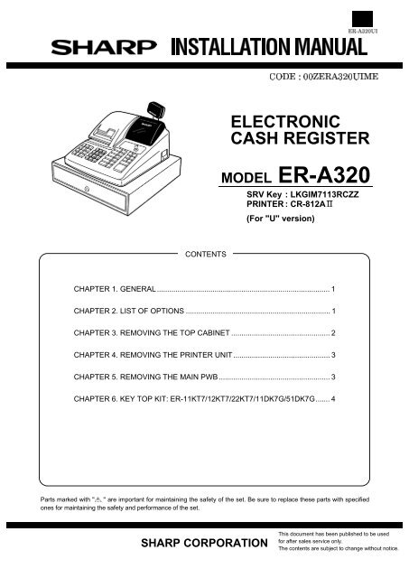
ELECTRONIC<br />
CASH REGISTER<br />
MODEL ER-A320<br />
SRV Key : LKGIM7113RCZZ<br />
PRINTER : CR-812A<br />
(For "U" v<strong>er</strong>sion)<br />
CHAPTER 1. GENERAL .................................................................................... 1<br />
CHAPTER 2. LIST OF OPTIONS ...................................................................... 1<br />
CHAPTER 3. REMOVING THE TOP CABINET ................................................ 2<br />
CHAPTER 4. REMOVING THE PRINTER UNIT ............................................... 3<br />
CHAPTER 5. REMOVING THE MAIN PWB ...................................................... 3<br />
CHAPTER 6. KEY TOP KIT: ER-11KT7/12KT7/22KT7/11DK7G/51DK7G....... 4<br />
Parts marked with " " are important for maintaining the safety of the set. Be sure to replace these parts with specified<br />
ones for maintaining the safety and p<strong>er</strong>formance of the set.<br />
SHARP CORPORATION<br />
This document has been published to be used<br />
for aft<strong>er</strong> sales s<strong>er</strong>vice only.<br />
The contents are subject to change without notice.
CHAPTER 1. GENERAL<br />
This manual describes the ER-A320 disassembly procedures and the<br />
option attachment procedures. For assembly procedures, rev<strong>er</strong>se the<br />
disassembly procedures. For attachment of options which do not require<br />
special descriptions, descriptions are omitted.<br />
Note for op<strong>er</strong>ations<br />
· Before op<strong>er</strong>ation, ground the op<strong>er</strong>ator’s body and p<strong>er</strong>form oth<strong>er</strong><br />
necessary measures against static electricity.<br />
· During op<strong>er</strong>ations, disconnect the AC cord from the outlet.<br />
· Aft<strong>er</strong> completion of op<strong>er</strong>ations, connect the connectors.<br />
· Aft<strong>er</strong> completion of op<strong>er</strong>ations, be sure to p<strong>er</strong>form the mast<strong>er</strong> reset.<br />
CHAPTER 2. LIST OF OPTIONS<br />
1. Sales options<br />
No. NAME MODEL DESCRIPTIONS<br />
1 COIN CASE ER-55C2 5B/5C(For "U" v<strong>er</strong>sion)<br />
2 KEY TOP KIT ER-11KT7 1 x 1 key top<br />
ER-12KT7 1 x 2 key top<br />
ER-22KT7 2 x 2 key top<br />
2. S<strong>er</strong>vice options<br />
ER-11DK7G 1 x 1 dummy key<br />
ER-51DK7G 5 x 1 dummy key<br />
Mast<strong>er</strong> reset (All memory clear)<br />
Used to clear all memory contents and return machine back to initial<br />
settings.<br />
(Returns keyboard back to the default keyboard layout.)<br />
Procedure<br />
1) Unplug the AC cord from the wall outlet.<br />
2) Set the MODE switch to the (SRV’) position.<br />
3) Plug in the AC cord to the wall outlet.<br />
4) While holding down JOURNAL FEED key, turn from (SRV’) position<br />
to the (SRV) position.<br />
Note: 1. The ER-A320 display will flash the "." decimal point at the<br />
right most position and will beep 3 times.<br />
2. The ER-A320 print<strong>er</strong> will cycle and print the following on the<br />
journal<br />
No. NAME PARTS CODE PRICE RANK DESCRIPTIONS<br />
1 SRV KEY AK<br />
2 MODE KEYGRIP COVER AL OP key only<br />
3 DRIP-PROOF KEYBOARD COVER BE<br />
3. Supplies<br />
No. NAME PARTS CODE PRICE RANK DESCRIPTIONS<br />
1 ROLL PAPER AR<br />
2 INK ROLLER AY<br />
3 INK FOR STAMP AK<br />
1
CHAPTER 3. REMOVING THE TOP<br />
CABINET<br />
1) Remove the print<strong>er</strong> cov<strong>er</strong> .<br />
2) Remove the three screws .<br />
3) Remove the screw and grounding wire .<br />
1 3<br />
2<br />
4) Separate the top cabinet and the draw<strong>er</strong> unit.<br />
Note: Transform<strong>er</strong> cable and the draw<strong>er</strong> cable on the draw<strong>er</strong><br />
unit are connected to the main PWB on the top cabinet.<br />
Be careful when separating them from the draw<strong>er</strong> unit.<br />
2<br />
2<br />
4<br />
5) Remove the transform<strong>er</strong> cable and the draw<strong>er</strong> cable from the<br />
main PWB.<br />
5<br />
6
CHAPTER 4. REMOVING THE<br />
PRINTER UNIT<br />
1) Remove the top cabinet.<br />
2) Remove the print<strong>er</strong> cable from the main PWB.<br />
3) Remove the three screws .<br />
4) Remove the screw and grounding wire .<br />
5) Remove the print<strong>er</strong> unit from the top cabinet.<br />
5<br />
2<br />
4<br />
Caution to be taken when replacing the print<strong>er</strong> unit<br />
Make sure to p<strong>er</strong>form the following procedure when installing the core<br />
to the grounding wire at the right side (when looking from the front<br />
side) of the print<strong>er</strong> unit.<br />
· View looking from the right side of the print<strong>er</strong> unit.<br />
Nylon band<br />
2<br />
Core Grounding wire<br />
Wind the grounding wire around the core by a turn and secure to the<br />
print<strong>er</strong> frame with the nylon band.<br />
3<br />
1<br />
CHAPTER 5. REMOVING THE MAIN<br />
PWB<br />
1) Remove the top cabinet.<br />
2) Remove the print<strong>er</strong> unit.<br />
3) Remove the following connector cables from the main PWB.<br />
Rechargeable batt<strong>er</strong>y cable<br />
Pop-up display cable<br />
Note: The pop-up cable is fixed with the hold<strong>er</strong> not to make contact<br />
with the heat radiating plate on the main PWB. Be<br />
careful of it when installing.<br />
Mode switch cable<br />
Keyboard cable<br />
4) Remove the screw and grounding wire .<br />
5) Remove the three screws and main PWB .<br />
8<br />
4<br />
3<br />
6<br />
1<br />
7 7<br />
Caution to be taken when installing the batt<strong>er</strong>y<br />
To prevent the batt<strong>er</strong>y from shorting due to wat<strong>er</strong> that might be<br />
splashed on the print<strong>er</strong> cov<strong>er</strong> or the keyboard, install the batt<strong>er</strong>y at an<br />
angle of 90° in relation to the keyboard.<br />
2<br />
90°<br />
5
CHAPTER 6. KEY TOP KIT<br />
1. Outline<br />
The ER-A320 employs the following key top (option) to allow additional<br />
installation of the key top and change in the key layout.<br />
MODEL NAME DESCRIPTION<br />
ER-11KT7 1 x 1 Key top<br />
ER-12KT7 1 x 2 Key top<br />
ER-22KT7 2 x 2 Key top<br />
ER-11DK7G 1 x 1 Dummy key<br />
ER-51DK7G 5 x 1 Dummy key<br />
2. Installation procedure<br />
ER-22KT7<br />
ER-11KT7<br />
ER-11KT7<br />
ER-12KT7<br />
ER-12KT7, ER-22KT7<br />
Note: Th<strong>er</strong>e are black spac<strong>er</strong>s and white spac<strong>er</strong>s. Ref<strong>er</strong> to the<br />
figure before for attaching them.<br />
· Attach the black spac<strong>er</strong> to the left low<strong>er</strong> side, and the white spac<strong>er</strong><br />
to the right low<strong>er</strong> side.<br />
ER-11DK7G, ER-51DK7G
COPYRIGHT ã 1999 BY SHARP CORPORATION<br />
All rights res<strong>er</strong>ved.<br />
Printed in Japan.<br />
No part of this publication may be reproduced,<br />
stored in a retrieval system, or transmitted.<br />
In any form or by any means,<br />
<strong>electronic</strong>, mechanical, photocopying, recording, or oth<strong>er</strong>wise,<br />
without prior written p<strong>er</strong>mission of the publish<strong>er</strong>.<br />
SHARP CORPORATION<br />
Information Systems Group<br />
Quality & Reliability Control Cent<strong>er</strong><br />
Yamatokoriyama, Nara 639-1186, Japan<br />
1999 Septemb<strong>er</strong> Printed in Japan