1000 kg Side Lift Jack - AL-KO
1000 kg Side Lift Jack - AL-KO
1000 kg Side Lift Jack - AL-KO
You also want an ePaper? Increase the reach of your titles
YUMPU automatically turns print PDFs into web optimized ePapers that Google loves.
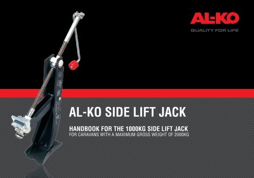
<strong>AL</strong>-<strong>KO</strong> SIDE LIFT JACK<br />
HANDBOOK FOR THE <strong>1000</strong>KG SIDE LIFT JACK<br />
FOR CARAVANS WITH A MAXIMUM GROSS WEIGHT OF 2000KG
CONTENTS<br />
3 WARNINGS & TECHNIC<strong>AL</strong> INFORMATION<br />
4 FITMENT OF JACK BRACKETS<br />
7 OPERATING INSTRUCTIONS<br />
8 TECHNIC<strong>AL</strong> DATA<br />
9 FAQS<br />
KIT CONTENTS<br />
1 x <strong>Side</strong> <strong>Lift</strong> <strong>Jack</strong><br />
1 x Storage Bag (if applicable)<br />
2 x Inner <strong>Jack</strong> Brackets<br />
2 x Outer <strong>Jack</strong> Brackets<br />
8 x M13 Washers<br />
4 x M12x35 Bolt<br />
4 x M12 Nylock Nut<br />
1 x Instructions<br />
Fig 1 <strong>AL</strong>-<strong>KO</strong> <strong>Side</strong> <strong>Lift</strong> <strong>Jack</strong> Kit<br />
2
WARNINGS<br />
TECHNIC<strong>AL</strong> INFORMATION<br />
1 NEVER LIE UNDERNEATH A JACKED-UP VEHICLE, AS<br />
THIS IS HIGHLY DANGEROUS AND COULD RESULT IN<br />
SERIOUS INJURY OR EVEN DEATH!<br />
2 The caravan MUST be attached to the towing vehicle<br />
and the handbrake on both the towing vehicle and<br />
caravan MUST be applied.<br />
3 The <strong>AL</strong>-<strong>KO</strong> Caravan <strong>Jack</strong> is not designed to be used<br />
as a permanent steady, but it can be used as an aid to<br />
levelling the caravan, in additional to changing the wheel.<br />
4 In the case of manual towing vehicles, select 1st or<br />
reverse gear; with automatic towing vehicles, place the<br />
selector lever in the ‘P’ position.<br />
5 As an additional safety measure, chock the caravan<br />
wheel (back and front) on the opposite side to the one<br />
to be changed.<br />
1 This product is suitable for use with caravans with a<br />
Maximum Gross Weight of 2000<strong>kg</strong> (<strong>1000</strong><strong>kg</strong> static load).<br />
2 The jack brackets can be attached to caravans fitted<br />
with <strong>AL</strong>-<strong>KO</strong> Chassis, manufactured from 1980.<br />
CARAVANS MANUFACTURED FROM 1980 - 1991<br />
Drilling of the chassis is required but only in accordance<br />
with the instructions printed in this handbook.<br />
CARAVANS MANUFACTURED AFTER 1991<br />
No drilling is required as the chassis frame will<br />
already have the pre-punched holes.<br />
3 These brackets can only be fitted to high frame<br />
chassis 215 mm.<br />
3
FITMENT OF JACK BRACKETS<br />
1 The jack mounting brackets can be fitted to both<br />
single and tandem axle caravans, on both sides of the<br />
chassis, behind the axle(s).<br />
NOTE<br />
Care should be taken to ensure the brackets do not<br />
interfere with any other equipment fitted in this area.<br />
Please observe minimum clearances as per Fig 2.<br />
2 On <strong>AL</strong>-<strong>KO</strong> chassis manufactured from 1991 onwards,<br />
the mounting holes are already incorporated into the<br />
longitudinal chassis members as standard.<br />
3 This jacking system can be fitted to most <strong>AL</strong>-<strong>KO</strong><br />
chassis manufactured from 1980 onwards.<br />
4 If your chassis was manufactured between 1980 and<br />
1991, it may be necessary to drill holes for the side<br />
lift jack.<br />
There are two possible locations in which you should<br />
drill the holes, and the most suitable location for<br />
your chassis can be determined as follows.<br />
Position a (Fig 3/a)<br />
If the criteria for 4a & 4b can be met then the holes should be<br />
drilled in position a, as illustrated at the top of Fig 3.<br />
4a The clearance from the rear of the wheel arch (Fig 3/item 1)<br />
to the centre of the spare wheel carrier mounting hole<br />
(Fig 3/item 2) must be a minimum of 95 mm.<br />
4b The lower face of the jack mounting bracket must hang<br />
below the lower face of the chassis member.<br />
Position b (Fig 3/b)<br />
If 4a & 4b cannot be met, the jack mounting brackets must be fit<br />
behind the spare wheel carrier, in holes drilled in position b, as<br />
illustrated at the bottom of Fig 3. Note the minimum clearance of<br />
55 mm from the centre of the spare wheel carrier mounting hole<br />
(Fig 3/item 3) to the centre of the hole for retro-fit set.<br />
NOTE<br />
Whether drilling in position a or b remember to apply corrosion<br />
protection (cold zinc galvanising spray) after drilling.<br />
CAUTION<br />
Use in well ventilated area and follow instructions on tin.<br />
4
FITMENT OF JACK BRACKETS<br />
a<br />
1<br />
38<br />
Min.<br />
160mm<br />
Fig 2 Minimum clearances<br />
Min.<br />
180mm<br />
A<br />
B<br />
C<br />
D 2<br />
FRAME HEIGHT HOLE SPACING HOLE DIA.<br />
A (mm) B (mm) C (mm) D (mm)<br />
215 40 55 13<br />
Fig 4 Drilling according to position ‘a’ (C Section Chassis Members)<br />
b<br />
A<br />
95<br />
MIN<br />
3<br />
D<br />
E<br />
F<br />
FRAME HEIGHT HOLE SPACING HOLE DIA.<br />
A (mm) E (mm) F (mm) D (mm)<br />
215 40 55 13<br />
Fig 5 Drilling according to position ‘b’ (C Section Chassis Members)<br />
Fig 3 Necessary cleanances for drilling holes<br />
55<br />
MIN<br />
5
FITMENT OF JACK BRACKETS<br />
5 Position the inner jack mounting bracket (Fig 6/item 1)<br />
with cutaway section of the bracket at the top edge, lining<br />
up the holes in the bracket, with those in the chassis.<br />
6 Fit 2 x M13 washers (Fig 6/item 2) onto the M12x35 Bolt<br />
head (Fig 6/item 4) and insert bolt through holes, with<br />
bolt head on inner side of chassis.<br />
7 Position the outer jack mounting bracket (Fig 6/item<br />
3), lining up the holes in the bracket, with those in the<br />
chassis member.<br />
8 Fit 2 x M13 washers (Fig 6/item 2) onto bolts.<br />
9 Fit the M12 self-locking nuts (Fig 6/item 5) and torque up<br />
to 86 Nm.<br />
M12X35<br />
BOLTS (4)<br />
M13<br />
WASHERS (2)<br />
INNER<br />
BRACKETS (1)<br />
Fig 6 Mounting the jack brackets<br />
M12<br />
NUTS (5)<br />
OUTER<br />
BRACKET (3)<br />
1<br />
2<br />
Fig 7 Attaching the jack to the jack brackets<br />
6
OPERATING INSTRUCTIONS<br />
1 Attach caravan to the towing vehicle and apply the<br />
handbrake on both towing vehicle and caravan.<br />
2 In the case of manual towing vehicles, select 1st or<br />
reverse gear; with automatic towing vehicles, place the<br />
selector lever in the ‘P’ position.<br />
3 As an additional safety measure ensure that you chock<br />
the caravan wheel (back and front) on the opposite side<br />
to the one to be changed.<br />
4 Clean jack mounting brackets on the caravan.<br />
5 Remove jack from storage bag (if applicable).<br />
6 Extend spare wheel carrier (if applicable) to remove<br />
spare wheel.<br />
7 If the ground is soft or likely to giveway, put a plank or<br />
something similar under the base plate of the jack.<br />
9 Holding the jack with one hand, turn the jack handle in a<br />
clockwise direction until the base plate reaches the ground.<br />
NOTE<br />
Wear gloves when winding up the jack to protect your hands<br />
against possible injury.<br />
10 Before operating jack, please check jack components are not<br />
catching on side overhang of caravan.<br />
CAUTION<br />
The base plate must sit flat on ground, vertical to chassis member.<br />
See fig 4. If these precautions are not observed; there is danger of<br />
damage to the vehicle jack or caravan.<br />
11 <strong>Lift</strong> caravan by continuing to turn the handle in a clockwise<br />
direction (only lift the vehicle until the wheel is no longer in<br />
contact with the ground (Max. 375mm)).<br />
8 Slot the insert piece (Fig 7/item 1) into the jack mounting<br />
bracket (Fig 7/item 2) until it connects.<br />
7
TECHNIC<strong>AL</strong> DATA<br />
Min. Ground Clearance Max. <strong>Lift</strong>ing Ht. Static Load<br />
A (mm) Fig 6a B (mm) Fig 6b (Kg)<br />
Fig 8 Technical data<br />
85 375 <strong>1000</strong><br />
WARNING<br />
NEVER LIE UNDERNEATH A JACKED-UP VEHICLE, AS THIS IS<br />
HIGHLY DANGEROUS AND COULD RESULT IN SERIOUS INJURY<br />
OR EVEN DEATH!<br />
A<br />
Fig 9 Min Ground clearance<br />
B<br />
Fig 10 Maximum lifting height<br />
Fig 11 Never lie underneath a jacked vehicle<br />
8
FAQS<br />
HOW DO I KNOW WHICH JACK I NEED?<br />
There are two side lift jacks kits available, the 2000<strong>kg</strong><br />
version and the 1600<strong>kg</strong> version. This figure is based on the<br />
maximum weight of the caravan. The jacks will lift a static<br />
load of <strong>1000</strong><strong>kg</strong> and 800<strong>kg</strong> respectively.<br />
WHY HAS MY BRACKET BENT?<br />
Is is vital that the jack and brackets be lined up as shown<br />
in Fig 7 on page 6. The joining section must be directly<br />
underneath the bracket, and the joining section must not<br />
enter the jack bracket at angle as this could put stress on the<br />
bracket and cause it to bend in use.<br />
HOW DO I STOP THE JACK SLIPPING?<br />
If the ground is soft or likely to give way, put a plank or<br />
something similar under the base plate of the jack.<br />
WHERE CAN I FIT THE JACK BRACKETS?<br />
The jack brakets are only suitable for fitment in either of the<br />
locations as shown in Fig 3 on page 5.<br />
9


