GB125 Concentric Vent - Buderus
GB125 Concentric Vent - Buderus
GB125 Concentric Vent - Buderus

You also want an ePaper? Increase the reach of your titles
YUMPU automatically turns print PDFs into web optimized ePapers that Google loves.
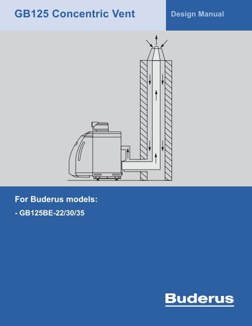
<strong>GB125</strong> <strong>Concentric</strong> <strong>Vent</strong><br />
Design Manual<br />
For <strong>Buderus</strong> models:<br />
- <strong>GB125</strong>BE-22/30/35
<strong>GB125</strong> <strong>Concentric</strong> <strong>Vent</strong><br />
Design Manual<br />
2 |<br />
Technical specifications are subject to change without prior notice<br />
<strong>GB125</strong> <strong>Concentric</strong> <strong>Vent</strong> Design Manual | 05 .2009
Applications manual<br />
Table of Contents<br />
<strong>GB125</strong> <strong>Concentric</strong> <strong>Vent</strong><br />
Design Manual<br />
1 General information 5<br />
1.1 This manual 5<br />
1.2 Standards, regulations and directives 5<br />
1.3 System certification 5<br />
5 Installing the flue gas system 9<br />
5.1 General installation notes 9<br />
5.2 Trimming pipes 9<br />
5.3 Installing the pipes 9<br />
5.4 Pipe disassembly 10<br />
2 Safety 6<br />
2.1 Intended use 6<br />
2.2 Layout of the instructions 6<br />
2.3 Please follow these instructions 6<br />
2.4 Tools, materials and accessories 6<br />
2.5 Disposal 6<br />
5.5 Appliance connection 10<br />
5.6 Installation and final assembly 10<br />
6 Inspecting the flue gas system 11<br />
7 Direct <strong>Vent</strong> - HTK <strong>Vent</strong>ing System kit 12<br />
8 Vertical <strong>Vent</strong> - DO <strong>Vent</strong>ing System kit 13<br />
3 Description of systems 7<br />
3.1 Scope 7<br />
3.2 Available systems 7<br />
9 Chimney Liner - GAK <strong>Vent</strong>ing System kit 15<br />
9.1 Installation in an existing chimney shaft 17<br />
9.2 Installation of rigid chimney pipe 18<br />
4 General requirements 8<br />
4.1 Installation requirments for the boiler room 8<br />
9.3 Flexible chimney liner - GAK system with<br />
UB flex 21<br />
9.4 Accessories for GAK systems 24<br />
4.2 Condensate drain 8<br />
4.3 Annual inspection 8<br />
4.4 Safety distances to combustible material 8<br />
4.5 Terminations 8<br />
4.6 Instructions for inspection and clean-out<br />
sections 8<br />
<strong>GB125</strong> <strong>Concentric</strong> <strong>Vent</strong> Design Manual | 05.2009<br />
Technical specifications are subject to change without prior notice<br />
| 3
<strong>GB125</strong> <strong>Concentric</strong> <strong>Vent</strong><br />
Design Manual<br />
4 |<br />
Technical specifications are subject to change without prior notice<br />
<strong>GB125</strong> <strong>Concentric</strong> <strong>Vent</strong> Design Manual | 05 .2009
Applications manual<br />
<strong>GB125</strong> <strong>Concentric</strong> <strong>Vent</strong><br />
Design Manual<br />
1. General information<br />
1.1. This manual<br />
These instructions contain important information for the<br />
safe and appropriate installation of the flue gas systems<br />
and system startup.<br />
It is a design guide for the venting system of the <strong>Buderus</strong><br />
<strong>GB125</strong> boiler, and it describes the prepackaged kits and<br />
their accessories, as well as important design<br />
considerations. It is intended for the installer during the<br />
planning phase and the actual installation.<br />
These instructions are designed for specialists, who -<br />
through their training and experience - are knowledgeable<br />
in the installation and servicing of heating systems and oil<br />
installations.<br />
This document is a supplement to the boiler manuals and<br />
the instructions included with the venting system.<br />
1.2. Standards, regulations and directives<br />
It is the responsibility of the installer to ensure that the<br />
system corresponds to all current building codes and<br />
regulations.<br />
1.3. System certification<br />
For <strong>Buderus</strong> <strong>GB125</strong> oil condensing boilers:<br />
The <strong>GB125</strong> is system-certified with this flue gas system for<br />
the USA and Canada by CSA International.<br />
An individual approval of the flue gas system is not<br />
required.<br />
The flue gas system must be installed in accordance with<br />
the installation instructions. The maximum permissible<br />
overall length and the number of changes of direction are<br />
specified on page 7.<br />
<strong>GB125</strong> <strong>Concentric</strong> <strong>Vent</strong> Design Manual | 05.2009<br />
Technical specifications are subject to change without prior notice<br />
| 5
<strong>GB125</strong> <strong>Concentric</strong> <strong>Vent</strong><br />
Design Manual<br />
2. Safety<br />
2.3. Please follow these instructions<br />
2.1. Intended use<br />
This concentric venting system may be used as flue gas<br />
system for <strong>Buderus</strong> oil condensing boilers with maximum<br />
flue gas temperatures of 248 °F (120 °C). Suitable are<br />
boilers of the types:<br />
– Logano plus <strong>GB125</strong>BE-22/30/35<br />
2.2. Layout of the instructions<br />
Two levels of danger are identified and signified by the<br />
following terms:<br />
WARNING! RISK OF FATAL INJURY<br />
Identifies possible dangers emanating from a<br />
product, which might cause serious injury or<br />
death if appropriate care is not taken.<br />
CAUTION! RISK OF INJURY/SYSTEM<br />
DAMAGE<br />
Indicates a potentially dangerous situation that<br />
could cause minor or moderately serious<br />
injuries and damage to property.<br />
WARNING! RISK OF FATAL INJURY FROM<br />
FLUE GAS AND CARBON MONOXIDE<br />
POISONING.<br />
Insufficient ventilation or leaky flue gas pipes may<br />
cause dangerous flue gas leaks.<br />
– Ensure that air intake or exhaust air vents are<br />
not closed off or their size reduced.<br />
– The boiler must not be operated until the<br />
obstruction has been removed.<br />
– Inform the system user in writing of the fault<br />
and its associated dangers.<br />
WARNING! RISK OF DEATH FROM FALLING.<br />
Take sufficient measures to prevent accidents on<br />
the roof.<br />
Use state of the art safety equipment and take<br />
common sense safety measures.<br />
WARNING! RISK OF INJURY OR DEATH FROM<br />
TOOLS AND EQUIPMENT FALLING FROM THE<br />
ROOF.<br />
Secure tools and equipment against falling from<br />
the roof.<br />
Additional symbols for identification of dangers and user<br />
instructions:<br />
Only use original <strong>Buderus</strong> spare parts.<br />
Damage caused by the use of parts not supplied<br />
by <strong>Buderus</strong> is excluded from the <strong>Buderus</strong><br />
warranty.<br />
USER NOTE<br />
User tips for optimal use of equipment and<br />
adjustment as well as other useful information.<br />
2.4. Tools, materials and accessories<br />
For the installation of the boiler, you will need standard<br />
tools used for central heating, oil boiler and DHW water<br />
systems.<br />
Additional tools needed are described in the appropriate<br />
section of these instructions.<br />
2.5. Disposal<br />
– Dispose of the packaging of the flue gas system in an<br />
environmentally responsible manner.<br />
– Dispose of defunct components of the flue gas system<br />
through an authorized agent in an environmentally<br />
responsible manner.<br />
6 |<br />
Technical specifications are subject to change without prior notice<br />
<strong>GB125</strong> <strong>Concentric</strong> <strong>Vent</strong> Design Manual | 05 .2009
Applications manual<br />
<strong>GB125</strong> <strong>Concentric</strong> <strong>Vent</strong><br />
Design Manual<br />
3. Description of the systems<br />
3.1. Scope<br />
The concentric venting system described in this manual<br />
is used exclusively for the <strong>Buderus</strong> <strong>GB125</strong> boiler. No<br />
other venting system can be used with this boiler, and the<br />
venting system can not be used in conjunction with any<br />
other boiler.<br />
Do not replace or substitute any vent or combustion air<br />
pipe with another brand, make, model, or material.<br />
The <strong>Buderus</strong> <strong>GB125</strong> is designed for balanced flue<br />
operation only. All combustion air is drawn from the<br />
outdoors. Use of balancers or barometric dampers defies<br />
the system principle and is not permitted.<br />
HTK - Direct vent through<br />
side wall<br />
(See page 12)<br />
Part Number: 7747310386<br />
DO - Vertical vent through<br />
conditioned and unconditioned<br />
space (NOT -suitable<br />
for installation outdoors)<br />
(See page 13)<br />
Part Number: 7747200752<br />
Installation and service of <strong>Buderus</strong> concentric venting<br />
systems must be performed by a trained installer.<br />
CAUTION! Never connect this concentric vent to<br />
a common venting system<br />
3.2. Available systems<br />
GAK - Liner inside an existing<br />
chimney;<br />
Option 1: rigid pipe for a<br />
straight chimney;<br />
Option 2: flexible liner for<br />
chimneys with an offset or<br />
bend;<br />
(See page 15)<br />
Part Number: 7747200755<br />
The three types of systems that are available are shown<br />
in Fig. 1:<br />
Observe the maximum vent lengths for each boiler size<br />
as shown in Table 1.<br />
Fig.1<br />
Available systems<br />
Systems are available as prepackaged kits that include<br />
the essential components needed in every installation.<br />
Refer to the descriptions of the individual system for<br />
included items. For most systems extra straight pipe and<br />
additional elbows must be purchased as needed. See list<br />
of accessories for every system.<br />
Max. length of flue pipe, feet (m)<br />
<strong>Buderus</strong> flue pipe systems DN 80/125 Table 1<br />
Boiler Size HT-K direct<br />
vent<br />
DO<br />
vertical vent<br />
GAK<br />
chimney<br />
liner<br />
<strong>GB125</strong> - 22 17' (5.2 m) 51' (17 m) 51' (17 m)<br />
<strong>GB125</strong> - 30 17' (5.2 m) 64' (21 m) 64' (21 m)<br />
The GAK system draws combustion air from the<br />
roof and may not be suitable for installation in<br />
multi-flue chimneys, where a second flue vents a<br />
combustion appliance that is used on a regular<br />
basis. Flue gases could be drawn in with <strong>GB125</strong><br />
combustion air and cause system interruption.<br />
<strong>GB125</strong> - 35 17' (5.2 m) 71' (23 m) 71' (23 m)<br />
The overall lengths include two elbows for the HT-K, and<br />
one elbow for the DO and GAK kits. Every additional<br />
elbow (accessory) reduces the maximum vent length by 3<br />
ft (1 m).<br />
| 7<br />
<strong>GB125</strong> <strong>Concentric</strong> <strong>Vent</strong> Design Manual | 05.2009<br />
Technical specifications are subject to change without prior notice
<strong>GB125</strong> <strong>Concentric</strong> <strong>Vent</strong><br />
Design Manual<br />
4. General requirements<br />
4.1. Installation requirements for the boiler<br />
room<br />
The <strong>GB125</strong> is designed for balanced flue operation only.<br />
All combustion air is drawn from outdoors.<br />
Allow ample room at the back of the boiler for servicing of<br />
the secondary heat exchanger.<br />
4.2. Condensate drain<br />
The boiler has an integrated condensate drain in the<br />
secondary heat exchanger. The condensate from the vent<br />
pipe flows directly into the boiler’s trap (siphon). This<br />
requires that all horizontal vent pipes are pitched at ⅝<br />
inch per foot (55 mm per meter) toward the appliance,<br />
including the horizontal termination (HTK-kit only). No<br />
second condensate drain is needed.<br />
Note that the siphon float must be cleaned at<br />
least once a year to ensure safe and proper<br />
operation.<br />
4.5. Terminations<br />
Terminations must be so positioned as to avoid products<br />
of combustion entering openings into buildings or other<br />
flues or vents.<br />
The <strong>Buderus</strong> concentric vent is designed for indoor<br />
installation in conditioned and unconditioned spaces only.<br />
Only the end of the termination is protected from UVradiation<br />
(direct sunlight) and the weather. None of the<br />
other pipes or elbows may be installed outdoors.<br />
4.6. Instructions for inspection and clean-out<br />
sections<br />
Local codes and regulations may require access to the<br />
vent pipe for inspection and clean-out. <strong>Buderus</strong> offers an<br />
inspection and clean-out section that allows inspecting<br />
and cleaning the venting system without dismantling.<br />
Part number<br />
Description<br />
87094587 clean out straight pipe<br />
Table 2<br />
The <strong>Buderus</strong> <strong>GB125</strong>BE boiler comes with a condensate<br />
neutralizer that must be properly maintained. Follow local<br />
rules when draining condensate into municipal sewage<br />
systems. It is not recommended to drain untreated<br />
condensate into septic systems. In any case follow local<br />
codes and regulations.<br />
4.3. Annual inspection<br />
The venting system must be inspected annually for signs<br />
of damage or condensate leaks. If the venting system<br />
appears damaged, the appliance must be turned off and<br />
the venting system repaired.<br />
4.4. Safety distances to combustible material<br />
The design of the concentric venting system allows<br />
installation with zero (0” (0 mm)) clearance to<br />
combustibles. Therefore, no particular protective<br />
measures or safety distances are required to combustible<br />
material or furniture.<br />
Note that the GAK chimney liner basic kit<br />
includes the above clean out section.<br />
The inspection and clean-out section (Fig. 9, page 15)<br />
must be installed sideways in the horizontal section of the<br />
flue gas pipe as the first section after the boiler adapter.<br />
Keep an area of at least 3 ft. x 3 ft. (1 m x 1 m) clearance<br />
in front of the inspection section for access.<br />
An upper inspection section may be needed if there are<br />
any changes in direction, e.g. when elbows are used to<br />
create an offset. Install the inspection and clean-out<br />
section in the horizontal run above the change in<br />
direction.<br />
Keep an area of at least 1-1/2 ft. x 1-1/2 ft. (0.5 m x 0.5<br />
m) clearance in front of the upper inspection section for<br />
easy access.<br />
8 |<br />
Technical specifications are subject to change without prior notice<br />
<strong>GB125</strong> <strong>Concentric</strong> <strong>Vent</strong> Design Manual | 05 .2009
Applications manual<br />
<strong>GB125</strong> <strong>Concentric</strong> <strong>Vent</strong><br />
Design Manual<br />
5. Installing the flue gas system<br />
5.1. General installation notes<br />
WARNING! RISK OF DEATH FROM LEAKING<br />
FLUE GASES.<br />
Improper installation of venting system and<br />
components or failure to follow all installation<br />
instructions can result in property damage or<br />
serious injury.<br />
5.2. Trimming pipes<br />
CAUTION! RISK OF INJURY FROM SHARP<br />
EDGES.<br />
Wear work gloves.<br />
– With concentric pipes, pull the inner pipe out of the<br />
outer pipe in the direction of the gasket.<br />
– Trim pipes at a right angle to the required length x<br />
(Fig. 2).<br />
– Trim the same length off the flue gas and air intake<br />
pipes.<br />
– Carefully remove burrs from cut edges; otherwise<br />
gaskets will get damaged, which can result in the<br />
system no longer being air tight and condensate to<br />
leak.<br />
– Reinstall the flue gas and air intake pipes.<br />
Fig. 2 Cuttting pipes<br />
X: Desired length<br />
5.3. Installing the pipes<br />
Pipes are assembled so that the sleeve points in the<br />
direction of the flue gas stream, with the gasket on the far<br />
side of the pipe when viewed from the boiler. Only use<br />
original <strong>Buderus</strong> flue gas pipe gaskets!<br />
– Coat the gaskets (Fig. 3 Item 1) and pipe ends with<br />
CENTROCERIN®<br />
gasket lubricant (supplied with the basic kit).<br />
– Push the flue gas pipes (Fig. 3 Item 2) into one another<br />
with a slight turning motion until the stop.<br />
– With concentric pipes, push the combustion air pipe<br />
(Fig. 3 Item 2) together to ensure a tight fit.<br />
– Verify that the gaskets did not shift.<br />
– Never use screws to hold pipe together.<br />
– If needed suspend pipe from the ceiling or the floor.<br />
Fig. 3 Pipe assembly<br />
1: Location of the gaskets<br />
2: Flue pipe<br />
3: Combustion air pipe<br />
<strong>GB125</strong> <strong>Concentric</strong> <strong>Vent</strong> Design Manual | 05.2009<br />
Technical specifications are subject to change without prior notice<br />
| 9
<strong>GB125</strong> <strong>Concentric</strong> <strong>Vent</strong><br />
Design Manual<br />
5.4. Pipe disassembly<br />
Pull the pipes apart while turning slightly.<br />
5.5. Appliance connection<br />
To install the appliance connector on the boiler, identify<br />
the gasketed connection in the bottom right corner at the<br />
back of the boiler.<br />
Apply CENTROCERIN® gasket lubricant on the gasket of<br />
the secondary heat exchanger and on the mating adapter<br />
pipe, and assemble with a slight turning motion. The<br />
combustion air pipe should be oriented in a 10-o’clock<br />
position with all 3 predrilled screw holes visible. (Fig. 4).<br />
Use the supplied brackets and self tapping screws to<br />
attach the adapter to the rear boiler panel.<br />
Connect the combustion air hose to the adapter and<br />
secure with the provided hose clamp.<br />
5.6. Installation and final assembly<br />
(1) Install the termination.<br />
(2) Follow the installation instructions to waterproof<br />
the penetration. Follow standard industry practice<br />
and consult a specialist if needed.<br />
(3) On the boiler install a clean out section immediately<br />
after the boiler adapter (if applicable).<br />
(4) Connect the termination with the boiler using straight<br />
concentric pieces and concentric elbows as required<br />
by the installation site. Sections can be cut to length<br />
per the procedure shown on page 9.<br />
(5) After cutting to the appropriate length, coat gaskets<br />
and mating pipes with CENTROCERIN® gasket<br />
lubricant and slide the pieces together with a slight<br />
turning motion.<br />
(6) Sections longer than 6 ft. (2 m) must be supported<br />
with bracing or clamps. Do not use the termination or<br />
the boiler adapter to support the venting system.<br />
Fig. 4<br />
Appliance connection<br />
It is the installer’s responsibility to ensure that the<br />
vent pipe is securely attached and supported as<br />
required by the site, and cannot accidentally<br />
disintegrate.<br />
1 0 |<br />
Technical specifications are subject to change without prior notice<br />
<strong>GB125</strong> <strong>Concentric</strong> <strong>Vent</strong> Design Manual | 05 .2009
Applications manual<br />
<strong>GB125</strong> <strong>Concentric</strong> <strong>Vent</strong><br />
Design Manual<br />
6. Inspecting the flue gas system<br />
To ensure that no leaks occur during operation, the venting<br />
system must be checked for leaks before startup.<br />
The flue gas line is sufficiently tight if the combustion air<br />
intake at the boiler adapter measures no higher than 0.2%<br />
CO ² , or a minimum of 20.6% O ² (ring gap test).<br />
WARNING! RISK OF FLUE GAS POISONING.<br />
Leaky flue gas lines may cause dangerous flue gas<br />
leaks.<br />
Take the boiler out of operation until the leak in the<br />
flue gas line has been eliminated.<br />
<strong>GB125</strong> <strong>Concentric</strong> <strong>Vent</strong> Design Manual | 05.2009<br />
Technical specifications are subject to change without prior notice<br />
| 11
<strong>GB125</strong> <strong>Concentric</strong> <strong>Vent</strong><br />
Design Manual<br />
7. Direct <strong>Vent</strong> – HTK <strong>Vent</strong>ing System kit<br />
Table 3<br />
The HTK kit contains essential pieces for a concentric<br />
pipe-in-pipe direct vent application with sealed<br />
combustion from boiler to termination (Fig. 5).<br />
Part Number Description Qty<br />
1 7747016312 <strong>Concentric</strong> boiler connector<br />
DN80/125 for <strong>GB125</strong><br />
1<br />
The kit (Fig. 5, Table 3) comes complete with a direct vent<br />
termination, 2 elbows, the boiler adapter, and some<br />
straight pipe. If needed, additional straight pipe sections,<br />
an inspection and clean out piece, as well as additional<br />
elbows must be purchased separately. See table 4 for a<br />
complete list of accessories.<br />
Choosing the right location for the terminal is critical to<br />
proper and safe operation of the appliance. Consult the<br />
HTK Installation Manual for details and limitations of the<br />
direct venting system.<br />
A ⅝ inch per foot (55 mm per meter) pitch to the<br />
appliance is needed for all horizontal pipe runs including<br />
the termination.<br />
Inform the homeowner or system operator of the potential<br />
appearance of a steam plume in cold climates.<br />
Ice can develop on the termination in cold climates.<br />
Ensure that ice formation does not pose a hazard on<br />
public walkways.<br />
Each boiler must be vented with a separate system.<br />
2 87094574 <strong>Concentric</strong> Elbow DN80/125x87<br />
- 90 degrees<br />
3 87094560 <strong>Concentric</strong> Pipe DN80/125x1000<br />
– 39“ (1000mm)<br />
4 7747213564 <strong>Concentric</strong> Wall Termination<br />
DN80/125 with inside and outside<br />
flashings<br />
2<br />
1<br />
1<br />
In the Commonwealth of Massachusetts a direct<br />
vent boiler is required to be accompanied by CO<br />
detectors per 527 CMR 31.00.<br />
Fig. 5<br />
HTK-kit<br />
Included items in basic kit<br />
Before starting any installation work, ensure that all<br />
included items are present (Table 3), plus any additional<br />
pieces (Table 4) needed to complete the job.<br />
Table 4<br />
Part Number Description<br />
87094587 <strong>Concentric</strong> inspection pipe<br />
87094556 <strong>Concentric</strong> Pipe DN80/125x500 19“ (500 mm)<br />
87094560 <strong>Concentric</strong> Pipe DN80/125x1000 39“ (1000 mm)<br />
87094600 <strong>Concentric</strong> Pipe DN80/125x2000 78“ (2000 mm)<br />
87094580 <strong>Concentric</strong> Elbow DN80/125x15 15 degrees<br />
87094576 <strong>Concentric</strong> Elbow DN80/125x30 30 degrees<br />
87094570 <strong>Concentric</strong> Elbow DN80/125x45 45 degrees<br />
87094574 <strong>Concentric</strong> Elbow DN80/125x87 90 degrees<br />
1 2 |<br />
Technical specifications are subject to change without prior notice<br />
<strong>GB125</strong> <strong>Concentric</strong> <strong>Vent</strong> Design Manual | 05 .2009
Applications manual<br />
<strong>GB125</strong> <strong>Concentric</strong> <strong>Vent</strong><br />
Design Manual<br />
8. Vertical <strong>Vent</strong> – DO <strong>Vent</strong>ing System kit<br />
The DO kit (Fig. 6) is suitable for new construction and<br />
retrofits, and allows a quick and simple chimney<br />
installation through the roof.<br />
The DO-kit contains essential pieces for a concentric<br />
pipe-in-pipe vertical vent application with sealed<br />
combustion from boiler to termination.<br />
Each boiler must be vented with a separate system.<br />
The kit (Fig. 6) comes complete with a vertical<br />
termination, the boiler adapter, and some straight pipe.<br />
Additional straight pipe sections, an inspection and clean<br />
out piece, a suitable roof jack or collar (Fig. 7 & 8), as<br />
well as at least one elbow must be purchased separately.<br />
Included items in basic kit<br />
Before starting any installation work, ensure that all<br />
included items (Table 5) are present, plus any additional<br />
pieces (Table 6) needed to complete the job.<br />
Table 5<br />
Part Description Qty<br />
1 7747016312 <strong>Concentric</strong> boiler connector<br />
DN80/125 for <strong>GB125</strong><br />
1<br />
Fig. 6<br />
DO-kit<br />
2 87092168 Adjustable face plate 1<br />
3 87092172 Rafter support clamp 1<br />
4 87090520 Adapter pipe 1<br />
5 87090520 <strong>Concentric</strong> extension pipe 1<br />
6 87090528 <strong>Concentric</strong> vertical roof termination<br />
black<br />
1<br />
Fig. 7<br />
Flat roof collars<br />
Install all horizontal runs with a 5/8 inch per foot (55 mm<br />
per meter) pitch to the appliance to allow condensate to<br />
drain properly.<br />
Fig. 8<br />
2-piece roof jack for sloped roofs<br />
<strong>GB125</strong> <strong>Concentric</strong> <strong>Vent</strong> Design Manual | 05.2009<br />
Technical specifications are subject to change without prior notice<br />
| 13
<strong>GB125</strong> <strong>Concentric</strong> <strong>Vent</strong><br />
Design Manual<br />
Accessories for DO System<br />
Select the appropriate roof jack or collar for the<br />
application based on roof pitch and roof type. It is<br />
recommended to consult a professional roofing contractor<br />
to ensure structural damage to the building from leaks is<br />
avoided.<br />
Table 6<br />
Part Number<br />
Description<br />
87094912 Roof collar flat roof H x DIA 3-1/2”x19-<br />
1/2”(90x500mm) for DO-system<br />
87094904 Roof collar flat roof H x DIA 9-1/2”x19-<br />
1/2”(240x500mm) for DO-system<br />
87094812 Roof jack 5-25° (12/1 to 12/6 pitch) for DOsystem<br />
87094814 Roof jack 35-55° (12/8 to 12/18 pitch) for DOsystem<br />
87094587 <strong>Concentric</strong> inspection Tee<br />
87094556 <strong>Concentric</strong> Pipe DN80/125x500 19“ (500mm)<br />
87094560 <strong>Concentric</strong> Pipe DN80/125x1000 39“ (1000mm)<br />
87094600 <strong>Concentric</strong> Pipe DN80/125x2000 78“ (2000mm)<br />
87094580 <strong>Concentric</strong> Elbow DN80/125x15 15 degrees<br />
87094576 <strong>Concentric</strong> Elbow DN80/125x30 30 degrees<br />
87094570 <strong>Concentric</strong> Elbow DN80/125x45 45 degrees<br />
87094574 <strong>Concentric</strong> Elbow DN80/125x87 90 degrees<br />
For more details consult the DO installation manual.<br />
1 4 |<br />
Technical specifications are subject to change without prior notice<br />
<strong>GB125</strong> <strong>Concentric</strong> <strong>Vent</strong> Design Manual | 05 .2009
Applications manual<br />
<strong>GB125</strong> <strong>Concentric</strong> <strong>Vent</strong><br />
Design Manual<br />
9. Chimney Liner – GAK <strong>Vent</strong>ing System<br />
kit<br />
Use the GAK kit for installations with an existing masonry<br />
chimney in good condition. It consists of concentric<br />
DN80/125 pipe-in-pipe from the boiler to the chimney, and<br />
inside the chimney chase a sealed DN80 plastic flue gas<br />
pipe runs up to the termination at the top. The space<br />
surrounding the flue gas pipe is used to draw combustion<br />
air from the roof to the boiler.<br />
The GAK System ensures a sealed combustion system<br />
from the boiler to the termination.<br />
The GAK system draws combustion air from the<br />
roof and may not be suitable for installations with<br />
multi-flue chimneys, where a second flue vents a<br />
combustion appliance that is used on a regular<br />
basis. Flue gases could be drawn in with <strong>GB125</strong><br />
combustion air and cause service calls.<br />
CAUTION! Never connect this concentric vent to a<br />
common venting system<br />
The chimney flue must not be used with any other<br />
appliance or for any other purpose, must be in good<br />
condition, and must be thoroughly cleaned before<br />
conversion to GAK.<br />
You will need to purchase the basic kit GAK (DN125/80) in<br />
any case. For the content see Table 7 and Fig. 9. Select<br />
additional items and accessories from Tables 8-10 as<br />
needed.<br />
For installations in multi-flue chimneys with a risk of<br />
ambers from wood stoves or similar appliances<br />
reaching the top of the chimney, optional stainless<br />
steel terminations are available. See list of<br />
accessories (Tables 8-10).<br />
Minimum chimney chase dimensions to ensure sufficient<br />
supply of combustion air:<br />
Rectangular: 5” x 5” (120 mm × 120 mm)<br />
Round:<br />
DIA 5-1/2” (Ø 130 mm);<br />
If the chimney is not a straight run but has an offset or<br />
bend, you can still use the rigid pipe as long as the<br />
bottleneck is accessible for the installation of elbows. If<br />
inaccessible, use the GAK system with the UB Flex pipe<br />
(Page 21) instead.<br />
Fig. 9<br />
GAK basic kit<br />
<strong>GB125</strong> <strong>Concentric</strong> <strong>Vent</strong> Design Manual | 05.2009<br />
Technical specifications are subject to change without prior notice<br />
| 15
<strong>GB125</strong> <strong>Concentric</strong> <strong>Vent</strong><br />
Design Manual<br />
Included items in the GAK basic kit:<br />
Rigid Pipe for inside the chimney:<br />
Table 7<br />
Table 9<br />
Description<br />
Qty<br />
Part Number<br />
Description<br />
1 <strong>Concentric</strong> boiler adapter 1<br />
2 <strong>Concentric</strong> inspection Tee-joint 1<br />
3 <strong>Concentric</strong> pipe, DN125/80 39” (1000 mm) 1<br />
4 <strong>Concentric</strong> chimney penetration DN125/80 and<br />
chimney face plate, DN125<br />
1<br />
87092078 Single Pipe DN80x250 9.5“ (250mm)<br />
87094588 Single Pipe DN80x500 19” (500mm)<br />
87094592 Single Pipe DN80x1000 39“ (1000mm)<br />
87094596 Single Pipe DN80x2000 78“ (2000mm)<br />
87094652 Single Pipe Elbow DN80x15 15 degrees<br />
5 Load bearing elbow, DN 80, with bracing and<br />
support rail<br />
1<br />
87094648 Single Pipe Elbow DN80x30 30 degrees<br />
87094644 Single Pipe Elbow DN80x45 45 degrees<br />
6 2-Piece chimney spacer (set of 6) 1<br />
7 Termination, black , DN80, L = 20” (500 mm) and<br />
flue gas end pipe, black<br />
1<br />
87094614 2-Piece chimney spacer<br />
87094920 Stainless Steel Chimney Cover (for rigid pipe only)<br />
8 CENTROCERIN® gasket lubricant (not shown) 1<br />
Inside a chimney with inaccessible offset:<br />
Table 10<br />
Part Number<br />
Description<br />
Accessories for GAK System:<br />
Table 8<br />
Part Number Description<br />
87094556 <strong>Concentric</strong> Pipe DN80/125x500 19“ (050mm)<br />
87094560 <strong>Concentric</strong> Pipe DN80/125x1000 39“ (1000 mm)<br />
87094600 <strong>Concentric</strong> Pipe DN80/125x2000 78“ (2000 mm)<br />
87094580 <strong>Concentric</strong> Elbow DN80/125x15 15 degrees<br />
87094576 <strong>Concentric</strong> Elbow DN80/125x30 30 degrees<br />
87094570 <strong>Concentric</strong> Elbow DN80/125x45 45 degrees<br />
87094574 <strong>Concentric</strong> Elbow DN80/125x87 90 degrees<br />
87094036 UB-Flex kit DN83x12500 Flexible flue gas pipe<br />
40ft. (12.5m) Spacers (8)<br />
87092180 Chimney Top End Pipe (not needed with stainless<br />
steel chimney cover)<br />
87094668 Union for two UB Flex pipes (for tall chimneys<br />
>40ft. or repairs)<br />
87094672 Union from GAK rigid vent pipe to UB Flex pipe<br />
87094614 2-Piece chimney spacer<br />
87094676 Inspection and cleanout Tee for UB Flex<br />
(for installation inside the chimney)<br />
7747208685 Stainless Steel Chimney Cover (for UB Flex only)<br />
1 6 |<br />
Technical specifications are subject to change without prior notice<br />
<strong>GB125</strong> <strong>Concentric</strong> <strong>Vent</strong> Design Manual | 05 .2009
Applications manual<br />
<strong>GB125</strong> <strong>Concentric</strong> <strong>Vent</strong><br />
Design Manual<br />
9.1. Installation in an existing chimney shaft<br />
Before starting any installation work, ensure that all<br />
included items are present, plus any additional pieces<br />
needed to complete the job.<br />
The chimney must be thoroughly cleaned before<br />
installing the flue gas system. It is recommended<br />
to use a professional chimney sweep.<br />
If the chimney cannot be sufficiently cleaned, and<br />
dust generation is anticipated or residue of oil or<br />
solid fuel fired appliances remains, the DO or<br />
HTK systems should be used instead.<br />
Fig. 10 load bearing elbow installation<br />
1 Support rail<br />
2 Load bearing elbow<br />
A stainless steel chimney termination is available for<br />
installations with multi-flue chimneys and a risk of ambers<br />
from wood stoves or similar appliances reaching the top<br />
of the chimney. For details see page 24.<br />
If the chimney is not a straight run, verify that the bend is<br />
accessible for the installation of elbows. If it is<br />
inaccessible, use the UB Flex liner instead of rigid pipe.<br />
Determine the position of the chimney penetration in the<br />
boiler room. Position the hole into the chimney such that<br />
the vent pipe to the boiler adapter runs at a 5/8” pitch per<br />
foot (55mm per meter) to allow condensate to drain into<br />
the boiler reliably. The size of the opening must be<br />
sufficient to install the support rail as shown in Fig. 10.<br />
Drill a 3/8” (10 mm) hole in the rear wall of the chimney at<br />
1-3/8” (35 mm) above the bottom of the chimney<br />
penetration (Fig. 10). Shorten support rail (Fig. 10, Item<br />
1) if necessary and insert the rod into the hole. Lay the<br />
near end onto the bottom of the penetration and ensure it<br />
is level and rigid. After the chimney pipes have been<br />
installed and connections made, it will be mortared in<br />
place.<br />
Place load bearing elbow (Fig. 10, Item 2) in the middle<br />
of the support rail (Item 1) with its guide engaging with<br />
the rail.<br />
Use a rope to determine the exact length between the<br />
gasket of the load bearing elbow and the top of the<br />
chimney.<br />
Proceed to page 18 if you are using rigid pipe, or page 21<br />
for flexible liner UB flex.<br />
<strong>GB125</strong> <strong>Concentric</strong> <strong>Vent</strong> Design Manual | 05.2009<br />
Technical specifications are subject to change without prior notice<br />
| 17
<strong>GB125</strong> <strong>Concentric</strong> <strong>Vent</strong><br />
Design Manual<br />
9.2. Installation of Rigid Chimney Pipe<br />
The rigid pipe is best suited for straight chimney flues<br />
with no offsets, or requires offsets to be accessible for the<br />
installation of elbows. In all other cases use the UB Flex<br />
kit instead.<br />
If additional elbows are needed inside the chimney,<br />
complete the connection between the chimney<br />
penetration and the elbows first. Coat all gaskets and the<br />
mating pipes with CENTROCERIN® gasket lubricant and<br />
assemble using a slight turning motion.<br />
Before climbing onto the roof, prepare all pipes and<br />
spacers needed for the length of the chimney as<br />
measured in the previous step. Coat all gaskets and<br />
mating pipes with CENTROCERIN® gasket lubricant.<br />
Keep the spacers close by.<br />
Place the two halves of the spacer (Fig.11) around the<br />
pipe and join them together.<br />
The chimney must be thoroughly cleaned before<br />
installing the flue gas system. It is recommended<br />
to use a professional chimney sweep.<br />
Tools needed on the roof<br />
– <strong>Vent</strong> pipes with spacers attached<br />
– Black or stainless steel top end pipe<br />
– Chimney Cover<br />
– CENTROCERIN®<br />
– Hammer drill with masonry bit 1/4” (6mm)<br />
– 4 wall anchors and screws<br />
– Matching screwdriver<br />
– Tape measure<br />
– Carpet knife or similar<br />
Fig. 11 Spacer<br />
Insert flue gas pipes with the gasket facing up and<br />
equipped with spacer (Fig. 12 Item 1) from above into the<br />
chimney (Fig. 12, Item 2), until the pipe sleeve is a little<br />
above the upper edge of the chimney. Take the next flue<br />
gas pipe and join them together by turning slightly.<br />
WARNING! RISK OF DEATH FROM FALLING.<br />
Take sufficient measures to prevent accidents on<br />
the roof.<br />
Use state of the art safety equipment and take<br />
common sense safety measures.<br />
WARNING! RISK OF INJURY OR DEATH FROM<br />
TOOLS AND EQUIPMENT FALLING FROM THE<br />
ROOF.<br />
Secure tools and equipment against falling from<br />
the roof.<br />
Fig. 12 GAK chimney installation<br />
1 8 |<br />
Technical specifications are subject to change without prior notice<br />
<strong>GB125</strong> <strong>Concentric</strong> <strong>Vent</strong> Design Manual | 05 .2009
Applications manual<br />
<strong>GB125</strong> <strong>Concentric</strong> <strong>Vent</strong><br />
Design Manual<br />
Lower flue gas pipes further into the chimney and repeat<br />
the procedure for all other pipes until reaching the<br />
support elbow.<br />
Have a second person make the connection with the<br />
support elbow at the base of the chimney by slightly<br />
turning the pipe into the gasket. Push down from the top<br />
to ensure a secure connection.<br />
If installing the stainless steel chimney cover, proceed to<br />
page 24.<br />
For the black chimney cover, only the black pipe is UV<br />
proof and may be exposed to the elements above the<br />
roof. Adjust the length of the last white pipe so that the<br />
terminating black pipe extends at least 13” (330mm)<br />
above the top of the chimney where the cover will be<br />
attached. This will result in a minimum of 3” (75mm)<br />
clearance of the pipe above the cap.<br />
Remove the top of the chimney cover (Fig. 13, Item 1) by<br />
pulling it up. Ensure it is held by its leash. Push the cover<br />
over the terminating black pipe and verify that it fits the<br />
top of the chimney. The base can be trimmed to match<br />
the chimney crown by cutting along the lines shown in<br />
Fig. 14, Item 1.<br />
Set cover on the top of the chimney and mark 4 holes.<br />
Drill holes and insert wall anchors. Caulk around the<br />
perimeter of the cover to prevent rain water from entering<br />
the chimney and screw down firmly. Push upper part of<br />
the chimney cover over the flue gas pipe and press down<br />
until it snaps in place.<br />
Fig. 13 Chimney cover<br />
1 Chimney cover<br />
Fig. 14 Base of chimney cover<br />
1 Lines indicating where cover base can be cut to size.<br />
<strong>GB125</strong> <strong>Concentric</strong> <strong>Vent</strong> Design Manual | 05.2009<br />
Technical specifications are subject to change without prior notice<br />
| 19
<strong>GB125</strong> <strong>Concentric</strong> <strong>Vent</strong><br />
Design Manual<br />
Chimney connection<br />
The elbow and rail support the weight of the vent pipe<br />
inside the chimney. Ensure both are installed properly<br />
and provide support.<br />
Shorten the penetrating pipe and flue gas pipe so it<br />
extends approx. 2” (50 mm) beyond the face of the<br />
chimney (Fig. 15). Carefully remove the burrs from cut<br />
edges.<br />
Coat the gasket (Fig. 15, Item 2) of the concentric wall<br />
penetration and the mating pipe of the support elbow with<br />
CENTROCERIN® and assemble using a slight turning<br />
motion. Allow a 5/8” pitch per foot (55mm per meter)<br />
toward the boiler. Mortar the penetrating pipe in place.<br />
Slide on the face plate (Fig. 15, Item 1), and once the<br />
mortar has cured, mark and drill mounting holes, insert<br />
wall anchors, and screw on the face plate.<br />
Fig. 15 Chimney connection<br />
1 Face plate<br />
2 Gasket in chimney penetration<br />
Connection to the boiler<br />
Connect the inspection and clean-out pipe to the boiler<br />
adapter. Measure the remaining distance to the chimney<br />
penetration and complete the connection with concentric<br />
pipe as described in chapter 5.6.<br />
Ensure a 5/8” pitch per foot (55mm per meter) toward the<br />
boiler (Fig. 16).<br />
For more details consult the GAK installation manual.<br />
Fig. 16 Boiler connection<br />
2 0 |<br />
Technical specifications are subject to change without prior notice<br />
<strong>GB125</strong> <strong>Concentric</strong> <strong>Vent</strong> Design Manual | 05 .2009
Applications manual<br />
<strong>GB125</strong> <strong>Concentric</strong> <strong>Vent</strong><br />
Design Manual<br />
9.3. Flexible Chimney Liner – GAK System<br />
with UB Flex<br />
For chimneys with an offset, a flexible liner called UB Flex<br />
is available for parts or the complete length of the<br />
chimney. Other than the rigid pipe that rests on the load<br />
bearing elbow at the bottom of the chimney, the flexible<br />
pipe is suspended from the termination at the top of the<br />
chimney.<br />
Required parts in addition to the GAK basic kit for a<br />
UB Flex install:<br />
Included items in the UB Flex kit:<br />
Description<br />
1 Flexible flue gas pipe 40ft. (12.5 m) (part of item<br />
87094036)<br />
Table 11<br />
2 2-Piece chimney spacer (part of item 87094036) 8<br />
Qty<br />
1<br />
Part Number<br />
Description<br />
Table 10<br />
87094036 UB-Flex kit DN83x12500 Flexible flue gas pipe<br />
40ft. (12.5m)<br />
3 Split ring (part of item 8709 2180) (not needed<br />
with stainless steel cover)<br />
4 Chimney End Pipe (part of item 8709 2180)<br />
(not needed with stainless steel cover)<br />
1<br />
1<br />
The flexible UB Flex pipe can only be combined with the<br />
GAK system. Do not exceed the maximum vent length<br />
permitted for the size of the boiler (Table 2)<br />
Minimum chimney chase dimensions to ensure sufficient<br />
supply of combustion air:<br />
Rectangular: 5” x 5” (120 mm × 120 mm)<br />
Round: DIA 5-1/2” (Ø 130 mm);<br />
A stainless steel chimney termination is available for<br />
installations with multi-flue chimneys and a risk of ambers<br />
from wood stoves or similar appliances reaching the top<br />
of the chimney.<br />
The flexible liner may only be installed vertically<br />
with a minimum pitch of 15°, and never instead of<br />
an elbow or a horizontal section.<br />
You will need to purchase the GAK basic kit (Fig. 9), the<br />
UB Flex kit (Fig. 17), the Chimney top end pipe (if not<br />
using the stainless steel cover), plus additional concentric<br />
pipes and elbows to connect the chimney with the boiler.<br />
Prepare the system as described in Chapters 9 and 9.1,<br />
and when the load bearing elbow is in place, continue<br />
here to install the flexible liner.<br />
Fig. 17 UB Flex kit<br />
1 Flexible pipe, DN 83, 40’ (12.5m)<br />
2 Spacers DN 83<br />
3 Split ring for attachment to the cover<br />
4 UV proof top end pipe<br />
<strong>GB125</strong> <strong>Concentric</strong> <strong>Vent</strong> Design Manual | 05.2009<br />
Technical specifications are subject to change without prior notice<br />
| 21
<strong>GB125</strong> <strong>Concentric</strong> <strong>Vent</strong><br />
Design Manual<br />
To connect to the elbow at the bottom of the chimney, a<br />
smooth section of the UB Flex pipe is needed. If the UB<br />
Flex pipe has two corrugated ends, cut one of them off<br />
for it to end in a smooth section.<br />
After measuring the length of the chimney, prepare the<br />
flexible pipe and spacers for installation inside the<br />
chimney before climbing onto the roof again.<br />
all spacers are installed at least every 6 feet (2m), (Fig.<br />
18, Item 1). Lower the pipe further into the chimney and<br />
repeat the procedure until the pipe reaches the support<br />
elbow. Install an additional spacer within 3 feet (1 meter)<br />
of the chimney crown.<br />
Place the two halves of the spacer (Fig. 18, Item 1)<br />
around the pipe and join them together.<br />
Attach a spacer at least every 6 ft. (2 m). Install<br />
an extra spacer within 3 ft. (1 m) of the top of the<br />
chimney.<br />
Tools needed on the roof<br />
– UB-Flex pipe with spacers attached<br />
– Black end pipe and split ring – do not use GAK<br />
basic kit black end pipe<br />
– Chimney cover<br />
– CENTROCERIN®<br />
– Rope at least 9’ (3m) longer than the chimney<br />
height<br />
– Hammer drill with masonry bit 5/8” (6mm)<br />
– 4 wall anchors and screws<br />
– Matching screwdriver<br />
– Tape measure<br />
– Carpet knife or similar<br />
– Wrench or similar weight<br />
Fig. 18 Spacer installation<br />
1 Spacer<br />
2 Rope<br />
WARNING! RISK OF DEATH FROM FALLING.<br />
Take sufficient measures to prevent accidents on<br />
the roof.<br />
Use state of the art safety equipment and take<br />
common sense safety measures.<br />
WARNING! RISK OF INJURY OR DEATH FROM<br />
TOOLS AND EQUIPMENT FALLING FROM THE<br />
ROOF.<br />
Secure tools and equipment against falling from<br />
the roof.<br />
Grab the smooth end of the UB Flex pipe, and attach one<br />
end of the rope to it. Tie a wrench or similar weight to the<br />
other end of the rope. Lower the weight on the rope from<br />
above into the chimney followed by the pipe. A second<br />
person carefully pulls on the rope to get the pipe past any<br />
offset or obstacle in the chimney flue. The person on the<br />
roof slowly feeds the pipe into the chimney and ensures<br />
2 2 |<br />
Technical specifications are subject to change without prior notice<br />
<strong>GB125</strong> <strong>Concentric</strong> <strong>Vent</strong> Design Manual | 05 .2009
Applications manual<br />
<strong>GB125</strong> <strong>Concentric</strong> <strong>Vent</strong><br />
Design Manual<br />
Have the second person coat the gasket of the elbow and<br />
the mating smooth flexible pipe end with<br />
CENTROCERIN® and assemble pipe by slightly turning<br />
the pipe into the gasket (Fig. 19).<br />
On the roof cut the UB-Flex pipe approx. 18” (450mm)<br />
above the top of the chimney (Fig. 19) if using the<br />
composite cover, and flush with the top of the chimney if<br />
using the stainless steel cover.<br />
If installing the stainless steel chimney cover, proceed to<br />
page 24.<br />
If using the black chimney cover, remove the top of the<br />
chimney cover (Fig. 20, item 1) and ensure it is held by<br />
its leash. Center the cover over the top of the chimney<br />
(Fig. 20, item 4).<br />
The base of the chimney cover can be trimmed to size<br />
along the perforated lines (Fig. 20, item 5) to match the<br />
chimney crown. Mark and drill 4 holes, and insert wall<br />
anchors.<br />
Pull the flexible pipe from the underneath through the<br />
cover and hold the pipe with one hand. Put the cover<br />
down onto the chimney crown and pull the pipe up until<br />
tight.<br />
Slide the split ring (threads facing up) over the flexible<br />
pipe and let it snap into a groove in the cover. Turn the<br />
pipe until the nose in the split ring meets the notch in the<br />
cover.<br />
Fig. 19 UB chimney bottom<br />
1 Elbow<br />
2 Support rail<br />
3 Opening in chimney<br />
Caulk around the perimeter of the cover to prevent rain<br />
water from entering the chimney, and screw down firmly.<br />
When looking down into the flexible pipe, you should see<br />
a fairly straight pipe. If major twists and turns occur, pull<br />
up on the pipe and snap the split ring into a grove closer<br />
to the cover. Again ensure the nose in the split ring meets<br />
the notch in the cover.<br />
Cut the UB Flex pipe flush at the split ring. Screw the<br />
black top piece into the split ring until hand tight.<br />
Push upper part of the Chimney Cover over the flue gas<br />
pipe and press down until it snaps in place.<br />
Only black pipe is UV proof and may be exposed to the<br />
elements above the roof.<br />
For more details consult the GAK installation manual.<br />
Fig. 20 UB chimney cover<br />
1 Cover top (black)<br />
2 Top end pipe (black) - do not use GAK basic kit black end pipe<br />
3 Split ring (black)<br />
4 Chimney cover (black)<br />
<strong>GB125</strong> <strong>Concentric</strong> <strong>Vent</strong> Design Manual | 05.2009<br />
Technical specifications are subject to change without prior notice<br />
| 23
<strong>GB125</strong> <strong>Concentric</strong> <strong>Vent</strong><br />
Design Manual<br />
9.4. Accessories for GAK Systems<br />
Stainless steel Chimney Covers:<br />
A stainless steel chimney termination is available for<br />
installations with multi-flue chimneys and a risk of ambers<br />
from wood stoves or similar appliances reaching the top<br />
of the chimney, or where the looks of stainless steel are<br />
preferred.<br />
Stainless Steel Chimney Cover for Rigid Pipe<br />
The stainless steel cover replaces the composite top and<br />
end pipe.<br />
Table 12<br />
Part Number<br />
Description<br />
87094920 Stainless Steel Chimney Cover for GAK System<br />
non UB Flex<br />
Only the stainless steel pipe is UV proof and may be<br />
exposed to the elements above the roof.<br />
Adjust the last white pipe length so that the terminating<br />
stainless steel pipe extends at least 11” (280mm) above<br />
the top of the chimney crown where the cover will be<br />
sitting. This will result in a minimum of 3” (75mm)<br />
clearance of the pipe above the cap. The end pipe can<br />
always be trimmed later.<br />
Coat the gasket of the last white pipe and the mating<br />
stainless steel pipe with CENTROCERIN® and assemble<br />
using a slight turning motion.<br />
Fig. 21 GAK stainless chimney top<br />
1 Stainless steel end pipe 20” (500mm)<br />
2 Top cover<br />
3 Chimney Cover<br />
4 Last section of rigid white pipe<br />
Not labeled: Screws and wall anchors (4);<br />
Push the Chimney Cover over the terminating pipe. Using<br />
a pair of snips, the chimney cover can be trimmed to size<br />
to match the chimney crown.<br />
Set cover on the chimney and mark 4 holes. Drill holes<br />
and insert wall anchors. Caulk around the perimeter of<br />
the cover to prevent rain water from entering the<br />
chimney, then screw down firmly.<br />
The steel cable attached to the cover is not being<br />
used.<br />
2 4 |<br />
Technical specifications are subject to change without prior notice<br />
<strong>GB125</strong> <strong>Concentric</strong> <strong>Vent</strong> Design Manual | 05 .2009
Applications manual<br />
<strong>GB125</strong> <strong>Concentric</strong> <strong>Vent</strong><br />
Design Manual<br />
Stainless Steel Chimney Cover for UB Flex<br />
The stainless steel cover replaces the composite top and<br />
end pipe.<br />
Table 13<br />
Part Number<br />
Description<br />
7747208685 Stainless Steel Chimney Cover for GAK System<br />
with UB Flex<br />
Only the stainless steel pipe is UV proof and may be<br />
exposed to the elements above the roof.<br />
Cut off the smooth part of the UB Flex pipe and adjust its<br />
length so that it ends approximately 1” above the<br />
chimney crown where the chimney cover will be sitting.<br />
Disassemble the union and observe the arrow on the<br />
main body dictating the direction of the flue gases. The<br />
gray gasket faces up.<br />
Slide the threaded ring with the threads facing up over<br />
the UB flex pipe. Slide the split ring with the flange facing<br />
up over the corrugated UB flex pipe, and snap into the<br />
second grove. Slide the red gasket over the corrugated<br />
UB flex pipe and snap into the very first grove.<br />
Now insert the pipe so prepared into the main body of the<br />
union and screw the threaded ring in hand tight.<br />
Fig. 22 UB stainless chimney top<br />
1 Stainless steel end pipe<br />
2 Top cover<br />
3 Attachment piece for the UB flex pipe<br />
4 Chimney Cover<br />
5 UB flex pipe<br />
Not shown: Screws and wall anchors (4); steel cable to secure top<br />
during service<br />
Open the hose clamp, slide the union through from<br />
below, and let its upper collar rest against the clamp.<br />
Tighten the hose clamp until the union is held firmly in<br />
place.<br />
Set the complete chimney cover with the UB Flex pipe<br />
attached onto the chimney.<br />
When looking down into the chimney, you should see a<br />
fairly straight pipe. If major twists and turns occur, loosen<br />
the hose clamp and pull up on the union. If the pipe still<br />
has a lot of slack, disassemble the union and shorten the<br />
UB Flex pipe carefully. Reassemble and verify the pipe is<br />
now straight.<br />
Using a pair of snips, the chimney cover can be trimmed<br />
to to match the chimney crown. Mark and drill 4 holes,<br />
and insert wall anchors. Caulk around the perimeter of<br />
the cover to prevent rain water from entering the<br />
chimney. The removable top of the Chimney Cover<br />
comes with a wire leash to prevent it from taking off<br />
during service. Insert its loop underneath the cover at<br />
one of the corners and slide a screw through it. Screw all<br />
4 corners down firmly.<br />
Coat the gray gasket and the mating stainless steel pipe<br />
with CENTROCERIN®, insert the stainless steel end pipe<br />
into the union, set the top cover on to the pipe, and slide<br />
down as far as it goes.<br />
<strong>GB125</strong> <strong>Concentric</strong> <strong>Vent</strong> Design Manual | 05.2009<br />
Fig. 23 UB flex connector<br />
1 Stainless steel end pipe<br />
2 Chimney Top<br />
3 Chimney Cover<br />
4 Attachment piece for the UB flex pipe<br />
5 Red gasket<br />
6 UB Flex pipe<br />
7 Split ring<br />
8 Screw bottom<br />
Technical specifications are subject to change without prior notice<br />
| 25
<strong>GB125</strong> <strong>Concentric</strong> <strong>Vent</strong><br />
Design Manual<br />
Union for UB Flex Pipes<br />
Under certain circumstances it may be necessary to<br />
connect 2 UB-Flex pipes. Use the following union:<br />
Table 14<br />
Part Number<br />
Description<br />
87094668 Union for 2 UB Flex pipes<br />
Do not exceed the maximum vent length permitted based<br />
on the size of the boiler (Table 2).<br />
The union consists of a main body Fig. 25, item 5), 2 split<br />
rings (item 3), 2 red gaskets (item 4), and 2 identical<br />
screw top and bottom pieces (Item 2).<br />
Only perforated sections of the UB Flex pipe can be<br />
connected, and it is necessary to cut off any smooth<br />
section. Make cuts perfectly perpendicular to the pipe.<br />
Fig. 24 UB flex pipe union<br />
Disassemble the union and observe the arrows on the<br />
main body dictating the direction of the flue gas flow.<br />
Slide the threaded ring with the threads facing to the<br />
loose end over the UB flex pipe.<br />
Slide the split ring over the corrugated UB flex pipe with<br />
the flange facing the lose end, and snap into its second<br />
grove.<br />
Slide the red gasket over the UB flex pipe and snap into<br />
its very first grove.<br />
Now insert the pipe so prepared into the main body and<br />
screw the threaded ring in until hand tight.<br />
Repeat the same with the other end.<br />
Fig. 25 UB flex pipe union breakdown<br />
1 UB Flex pipe, cut off smooth section<br />
2 Screw top and bottom (2)<br />
3 Split ring (2x)<br />
4 Red gasket (2x)<br />
5 Center piece (arrow pointing in direction of flue gases)<br />
2 6 |<br />
Technical specifications are subject to change without prior notice<br />
<strong>GB125</strong> <strong>Concentric</strong> <strong>Vent</strong> Design Manual | 05 .2009
Applications manual<br />
<strong>GB125</strong> <strong>Concentric</strong> <strong>Vent</strong><br />
Design Manual<br />
Connecting a UB Flex Pipe with Rigid Pipe<br />
Under certain circumstances it may be necessary to<br />
connect a rigid pipe with a UB-Flex pipe. Use the<br />
following union:<br />
Table 15<br />
Part Number<br />
Description<br />
87094672 Connector from GAK rigid pipe to UB Flex pipe<br />
The flexible pipe UB Flex can only be combined with the<br />
GAK system. Do not exceed the maximum vent length<br />
permitted based on the size of the boiler (Table 2)<br />
The rigid pipe always has to be on the top and<br />
the UB Flex pipe on the bottom of the union.<br />
The union consists of a main body with a gray gasket<br />
installed (Fig. 26, item 2), 1 split ring (item 4), 1 red<br />
gasket (item 3), and 1 threaded bottom piece (Item 5).<br />
Item 1 is the rigid pipe, and item 6 the corrugated UB Flex<br />
pipe.<br />
Only the perforated section of the UB Flex pipe can be<br />
connected, and it is necessary to cut off any smooth<br />
section. Make cuts perfectly perpendicular to the pipe.<br />
Disassemble the union and observe the arrow on the<br />
main body dictating the direction of the flue gases. The<br />
gray gasket must face up.<br />
Fig. 26 UB flex pipe to rigid pipe connection<br />
1 Rigid vent pipe (must be at the top)<br />
2 Center piece (arrow pointing in direction of flue gases)<br />
3 Red gasket<br />
4 Split ring<br />
5 Screw bottom<br />
6 UB Flex pipe, cut off smooth section<br />
Slide the threaded ring with the threads facing up over<br />
the UB flex pipe. Slide the split ring over the UB flex pipe<br />
with the flange facing up, and snap into the second grove.<br />
Slide the red gasket over the corrugated UB flex pipe and<br />
snap into the very first grove.<br />
Now insert the pipe so prepared into the main body and<br />
screw the threaded ring in until hand tight.<br />
Coat the gray gasket and the mating pipe with<br />
CENTROCERIN® and insert the rigid pipe into the union<br />
by slightly turning the pipe into the gasket.<br />
Install a chimney spacer on the main body of the union.<br />
<strong>GB125</strong> <strong>Concentric</strong> <strong>Vent</strong> Design Manual | 05.2009<br />
Technical specifications are subject to change without prior notice<br />
| 27
<strong>GB125</strong> <strong>Concentric</strong> <strong>Vent</strong><br />
Design Manual<br />
Installing the Inspection and Cleanout Tee for UB<br />
Flex pipe<br />
A local jurisdiction may require an inspection and<br />
cleanout Tee to be installed in the vent pipe inside the<br />
chimney. The Tee is installed in similar fashion to the<br />
Union for UB Flex Pipes described above.<br />
Table 16<br />
Part Number<br />
Description<br />
87094676 Inspection and cleanout Tee for UB Flex<br />
It comes with a screw cap on the side that allows access<br />
for inspection and cleaning. It is installed at the bottom of<br />
the chimney just above the supporting elbow, and<br />
requires an access door in the chimney wall.<br />
2 8 |<br />
Technical specifications are subject to change without prior notice<br />
<strong>GB125</strong> <strong>Concentric</strong> <strong>Vent</strong> Design Manual | 05 .2009
Applications manual<br />
<strong>GB125</strong> <strong>Concentric</strong> <strong>Vent</strong><br />
Design Manual<br />
Notes:<br />
<strong>GB125</strong> <strong>Concentric</strong> <strong>Vent</strong> Design Manual | 05.2009<br />
Technical specifications are subject to change without prior notice<br />
| 29
<strong>GB125</strong> <strong>Concentric</strong> <strong>Vent</strong><br />
Design Manual<br />
3 0 |<br />
Technical specifications are subject to change without prior notice<br />
<strong>GB125</strong> <strong>Concentric</strong> <strong>Vent</strong> Design Manual | 05 .2009
Applications manual<br />
<strong>GB125</strong> <strong>Concentric</strong> <strong>Vent</strong><br />
Design Manual<br />
<strong>GB125</strong> <strong>Concentric</strong> <strong>Vent</strong> Design Manual | 05.2009<br />
Technical specifications are subject to change without prior notice<br />
| 31
Bosch Thermotechnology Corporation<br />
50 Wentworth Avenue<br />
Londonderry, NH 03053<br />
Tel.: 603-552-1100<br />
Fax: 603-584-1681<br />
www.buderus.net<br />
Products manufactured by:<br />
Bosch Thermotechnik GmbH<br />
Sophienstrasse 30-32<br />
D-35576 Wetzlar<br />
www.buderus.de<br />
BTC 410001101 A | 08.2009<br />
Bosch Thermotechnology Corporation reserves the right to<br />
make changes without notice due to continuing engineering<br />
and technological advances.