708373-0 Uncased Indoor Coil ii.PMD - Nordyne
708373-0 Uncased Indoor Coil ii.PMD - Nordyne
708373-0 Uncased Indoor Coil ii.PMD - Nordyne

You also want an ePaper? Increase the reach of your titles
YUMPU automatically turns print PDFs into web optimized ePapers that Google loves.
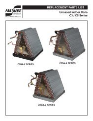
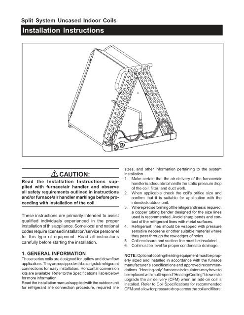
Split System <strong>Uncased</strong> <strong>Indoor</strong> <strong>Coil</strong>s<br />
Installation Instructions<br />
! CAUTION:<br />
Read the Installation Instructions supplied<br />
with furnace/air handler and observe<br />
all safety requirements outlined in instructions<br />
and/or furnace/air handler markings before proceeding<br />
with installation of the coil.<br />
These instructions are primarily intended to assist<br />
qualified individuals experienced in the proper<br />
installation of this appliance. Some local and national<br />
codes require licensed installation/service personnel<br />
for this type of equipment. Read all instructions<br />
carefully before starting the installation.<br />
1. GENERAL INFORMATION<br />
These series coils are designed for upflow and downflow<br />
applications. They are equipped with brazing stub refrigerant<br />
connections for easy installation. Horizontal conversion<br />
kits are available. Refer to the Specifications Table below<br />
for more information.<br />
Read the installation manual supplied with the outdoor unit<br />
for refrigerant line connection procedure, required line<br />
sizes, and other information pertaining to the system<br />
installation.<br />
1. Make certain that the air delivery of the furnace/air<br />
handler is adequate to handle the static pressure drop<br />
of the coil, filter, and duct work.<br />
2. When applicable check the coil's orifice size and<br />
confirm that it is suitable for application with the<br />
intended outdoor unit.<br />
3. Where precise forming of the refrigerant lines is required,<br />
a copper tubing bender designed for the size lines<br />
used is recommended. Avoid sharp bends and contact<br />
of the refrigerant lines with metal surfaces.<br />
4. Refrigerant lines should be wrapped with pressure<br />
sensitive neoprene or other suitable material where<br />
they pass through the raw edges of holes.<br />
5. <strong>Coil</strong> enclosure and suction line must be insulated.<br />
6. <strong>Coil</strong> must be level for proper condensate drainage.<br />
NOTE: Optional cooling/heating equipment must be properly<br />
sized and installed in accordance with the furnace<br />
manufacturer’s specifications and approved recommendations.<br />
“Heating only” furnace air circulators may have to<br />
be replaced with multi-speed “Heating/Cooling” blowers to<br />
upgrade the air delivery (CFM) when an add-on coil is<br />
installed. Refer to <strong>Coil</strong> Specifications for recommended<br />
CFM and allow for pressure drop across the coil and filters.
2. COIL SPECIFICATIONS<br />
<strong>Coil</strong> Model (1)<br />
C3BA C3BA C3BA C3BA C3BA C3BA C3BM C3BA C3BA C3BA C3BA<br />
024U-A 030U-A 036U-A 043U-A 030U-B 036U-B 036U-B 042U-B 048U-B 048U-C 060U-C<br />
Nominal (2)<br />
Capacity BTUH 24,000 30,000 36,000 43,000 30,000 36,000 36,000 42,000 48,000 48,000 60,000<br />
Nominal Airflow<br />
CFM (3) 900 1,125 1,200 1,400 1,100 1,350 1,350 1,500 1,500 1,600 1,800<br />
Orifice Size (in.) 0.060 0.063 0.067 0.080 0.063 0.067 0.067 0.075 0.080 0.080 0.093<br />
Width (in.) W 12 3/4 12 3/4 12 3/4 12 3/4 18 1/8 18 1/8 18 1/8 18 1/8 18 1/8 21 21<br />
Height (in.) H 15 18 7/8 19 1/2 23 1/4 19 1/2 19 1/2 15 19 1/2 19 1/2 19 1/2 23 1/4<br />
Connections (in.)<br />
Liquid Line 3/8 3/8 3/8 3/8 3/8 3/8 3/8 3/8 3/8 3/8 3/8<br />
Suction Line 3/4 3/4 3/4 3/4 3/4 3/4 3/4 3/4 3/4 3/4 7/8<br />
Horizontal Drain Kit 914633 917492 917492 914634 917492 917492 - 917492 917492 917492 914634<br />
<strong>Coil</strong> Model (1)<br />
C4BA-<br />
X24U-B<br />
C4BA-<br />
X36U-B<br />
C4BA-<br />
X48U-C<br />
C4BA-<br />
X60U-C<br />
Nominal (2)<br />
Capacity BTUH 24,000 36,000 48,000 60,000<br />
Nominal Airflow<br />
CFM (3) 900 1200 1500 1800<br />
Refrigerant Metering<br />
Device TXV TXV TXV TXV<br />
Width (in.) W 18 1/8 18 1/8 21 21<br />
Height (in.) H 19 1/2 25 28 28<br />
Connections (in.)<br />
Liquid Line 3/8 3/8 3/8 3/8<br />
Suction Line 3/4 7/8 7/8 7/8<br />
Horizontal Drain Kit 917492 914634 917188 917188<br />
1. Refer to sales specification sheets for Listed/Certified combinations of equipment and required accessories.<br />
2. Refer to the current ARI Directory for certified ratings of split systems.<br />
3. Based on a nominal 0.3" w.c. pressure drop across the coil.<br />
3. COIL INSTALLATION<br />
Upflow Furnace:<br />
! WARNING:<br />
Electric furnaces may be connected to more<br />
than one supply circuit.<br />
1. Disconnect all electrical power to the furnace.<br />
2. If needed, make a plate to adapt the coil to the furnace/<br />
air handler air discharge opening.<br />
3. Install the coil and level it as needed to allow proper<br />
condensate drainage.<br />
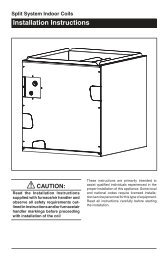
4. Make a plenum to enclose the coil or drop the duct<br />
directly over it. Insulate as required. (See Figure 2)<br />
5. Seal the enclosure as required to minimize air<br />
leakage.<br />
6. Connect the refrigerant lines as outlined in<br />
the Refrigerant Lines section.<br />
Downflow/Horizontal — These coils may be installed in<br />
downflow or horizontal applications. Installation of the coils<br />
in these applications only requires that the coil be securely<br />
mounted and that the proper horizontal drain kit be added.<br />
Refer to the Specifications section for the proper kit<br />
numbers.<br />
NOTE: If the coil is installed horizontally, a drain kit must<br />
be used.<br />
4. REFRIGERANT LINE CONNECTIONS<br />
NOTE: Before proceeding with the connection of the<br />
refrigerant lines, confirm that the orifice size meets the<br />
requirements outlined in the outdoor unit installation manual.<br />
Factory installed orifice sizes are listed in the Specifications<br />
section. If the restrictor orifice must be replaced, follow the<br />
steps below:<br />
NOTE: For coils with factory installed TXV valve proceed<br />
to step #7.<br />
2
1. Loosen the orifice body halves by applying two<br />
wrenches and squeezing them together as shown in<br />
Figure 3, to turn the assembly nut counter- clockwise.<br />
2. Continue to unscrew the assembly nut to separate it<br />
from the distributor body.<br />
3. Insert a light-gauge wire hook between the distributor<br />
body and the restrictor orifice to lift the orifice out of<br />
the body. (See Figure4) Carefully remove the restrictor<br />
orifice being careful not to scratch either part.<br />
4. Check the actual size of the new orifice. The size is<br />
stamped on its side. Do not use pin gages to measure<br />
the orifice diameter.<br />
5. Insert the new orifice in the distributor body, rounded<br />
end down. (See Figure 5)<br />
6. After installing the orifice in the distributor body, realign<br />
the assembly nut to the distributor body. Mark a line<br />
along both bodies after hand tightening and then tighten<br />
an additional 1/4 turn. Caution: Do not overtighten! The<br />
misalignment of the two lines will show how much the<br />
nut is tightened. If a torque wrench is used, tighten to<br />
10-12 ft. lbs. or 14-16 Nm.<br />
7. Remove the protective caps from the coil and refrigerant<br />
line set.<br />
8. Cut the line set tubing to the proper length. Be sure that<br />
the tubing has been sized in accord-ance with the<br />
outdoor unit specifications.<br />
9. Inspect both refrigerant lines. The ends of the lines<br />
must be round, clean, and free of any burrs.<br />
10. Insert the line set tubes into the coil tube stubs until they<br />
bottom out.<br />
11. Braze the individual connections with dry nitrogen<br />
flowing through the joints to eliminate internal oxidation<br />
and scaling.<br />
12. Check the assembly for leaks with dry nitrogen.<br />
5. COMPLETING THE INSTALLATION<br />
! CAUTION:<br />
The indoor coil must be checked to ensure a level<br />
installation. Failure to do so may result in improper<br />
condensate disposal, causing structural damage,<br />
premature equipment failure, or possible personal<br />
injury.<br />
Figure 1. B & C Cabinet <strong>Coil</strong><br />
Figure 2<br />
Condensate Drain:<br />
1. The coil condensate pan is furnished with 3/4" NPSC<br />
drain connections. Use a PVC or similar material fitting<br />
to attach the drain line to the pan. The fitting should be<br />
only hand tightened.<br />
Overtightening may crack the drain pan and create<br />
a condensate leak.<br />
2. Connect the drain line and run to a suitable drain<br />
avoiding sharp bends and pinching of the line. Install a<br />
condensate trap and prime with water.<br />
3. During the system checkout, inspect the drain line and<br />
connections to verify proper condensate disposal.<br />
Air Filter — Air filters are not provided as an integral part of<br />
this coil, however, a filter must be installed upstream of the<br />
coil and inspected frequently. When the filter becomes<br />
clogged with dust or lint, it should be replaced (disposable<br />
type) or cleaned (washable type). The filter should be<br />
inspected and replaced or cleaned at least twice during the<br />
year, generally at the start of each heating and cooling<br />
season.<br />
3
Close-Off Plates and Panels — Install the necessary air<br />
close-off plates around the refrigerant lines and drain line<br />
where required. Reinstall all inner and outer panels of the<br />
furnace/air handler that were previously removed to install<br />
the indoor coil.<br />
Refrigerant Charging — These indoor coils are not factory<br />
charged with refrigerant.<br />
It will be necessary to evacuate the indoor coil and line set<br />
prior to charging. Refer to the outdoor unit installation<br />
manual for detailed charging instructions.<br />
Figure 3. Wrenches on Distributor Body<br />
and Assembly Nut<br />
6. MAINTENANCE AND SERVICE<br />
! WARNING:<br />
Ensure that all electrical power to the furnace<br />
and outdoor (condensing) unit is off before<br />
performing any maintenance or service on the<br />
system.<br />
To ensure optimum system performance and to minimize<br />
the possibility of equipment failure, the following periodic<br />
maintenance should be performed on the coil:<br />
Figure 4. Removal of Orifice<br />
1. The air filter installed with the system should be<br />
checked and cleaned or replaced twice per year.<br />
2. Check the coil, drain pan, and condensate drain line for<br />
cleanliness at the start of each heating and cooling<br />
season. Clean and remove any debris as required.<br />
! CAUTION:<br />
Do not operate the system without having a<br />
suitable filter in place in the return air duct<br />
system. Always replace the filter with the same<br />
size and type.<br />
Figure 5. Restrictor Insertion in Distributor Body<br />
INSTALLER: PLEASE LEAVE THESE INSTALLATION<br />
INSTRUCTIONS WITH THE HOMEOWNER<br />
¢<strong>708373</strong>5¤<br />
<strong>708373</strong>0<br />
CERTIFICATION APPLIES ONLY<br />
WHEN THE COMPLETE<br />
SYSTEM IS LISTED<br />
WITH ARI<br />
<strong>708373</strong>0 (Replaces 707742C)<br />
Specifications and illustrations subject to change<br />
without notice and without incurring obligations.<br />
Printed in U.S.A. (5/04)