LF9648-V1_30-03- Prospekt - Martens Elektronik GmbH
LF9648-V1_30-03- Prospekt - Martens Elektronik GmbH
LF9648-V1_30-03- Prospekt - Martens Elektronik GmbH

Create successful ePaper yourself
Turn your PDF publications into a flip-book with our unique Google optimized e-Paper software.
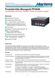
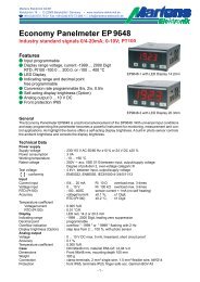
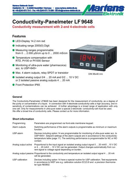
Conductivity-Panelmeter LF 9648<br />
Conductivity measurement with 2-and 4-electrode cells<br />
Features<br />
M LED-Display 14.2 mm red<br />
M Indicating range 2000(0) Digit<br />
M Measuring ranges programmable<br />
from 0 ... 2.000 μS/cm up to 0 ... 2000 mS/cm<br />
M Temperature compensation with<br />
RTD, Pt100 or Pt1000 Sensor<br />
M Monitoring of ultra-pure water (pharmacoica)<br />
acc. to USP<br />
M Max. 4 alarm outputs, relay SPDT or transistor<br />
M Isolated analog output 0/4 ... 20 mA and 0/2 ... 10 V DC<br />
or 2 isolated passive analog outputs 4 ... 20 mA<br />
M Front Protection IP65<br />
DIN 96x48 mm<br />
General<br />
The Conductivity-Panelmeter <strong>LF9648</strong> has been designed for the measurement of conductivity, as a degree of<br />
the purity or concentration of a liquid. In connection with 4-electrode-conductivity-cells a high accuracy, and insensitivity<br />
of contaminations can be achieved. A further advantage is a broad range of application with only<br />
one cell. Only for measurements in ultra-pure water a special 2-electrode- conductivity-cell must be used.<br />
We offer a broad line of conductivity cells. Please contact us for more information.<br />
Short information<br />
Programming<br />
Alarm outputs<br />
USP-alarm<br />
Analog output active<br />
Parameters are programmed via front-side membrane keypad.<br />
Switching performance of the alarm outputs is programmable as minimum or maximum<br />
function.<br />
Devices including option 14 are programmable for monitoring of ultra-pure water acc. to<br />
USP. Setpoint settings of the alarm outputs are in accordance to the conductivitytemperature<br />
table (page 11). The switching performance is programmable for NC or NO<br />
contact.<br />
Proportional to the input signal an isolated analog output signal 0 ... 20 mA/0 ...10 V DC<br />
or 4 ... 20 mA/2 ... 10 V DC can be generated. Output changes automatically from current<br />
signal to voltage signal depending on burden.<br />
Analog output passive Proportional to the conductivity and temperature an isolated output signal 4 ... 20 mA<br />
will be generated.<br />
USP calibration Devices including option 14 have a special routine for USP calibration. Test-equipments<br />
in accordance to NIST are e.g. calibration solution EC23.8 and a precision thermometer<br />
type N63802.<br />
- 1 -
Technical data<br />
Power supply<br />
Supply voltage : 2<strong>30</strong> V AC ±10 %; 115 V AC ±10 %, 24 V AC ±10 % or 24 V DC ±15 %<br />
Power consumption : max. 3.5 VA, with analog output 5 VA<br />
Operating temperature : -10 ... +55 °C<br />
Rated voltage<br />
: 250 V~ acc. VDE 0110 between input/output/supply voltage<br />
Degree of pollution 2, over-voltage category III<br />
Test voltage<br />
: 4 kV=, between input/output/supply voltage<br />
- conformity : EN55022, EN60555, IEC61000-4-3/4/5/11/13<br />
Inputs<br />
Conductivity input<br />
: 0 ... 2.000(0) μS/cm to 0 ... 2000 / 200(0) mS/cm (at 25 °C)<br />
-Cell constant : 0.080 ... 9.999<br />
-Accuracy<br />
: 0.5 % of the measuring range, ±2 Digit<br />
-Temperature comp. : non linear for pure and natural water or<br />
linear adjustable from 0.000 ... 9.999 %/K<br />
-Temperature coefficient : 0.02 %/K<br />
Temperature input : -50.0 ... 200.0 °C; RTD Sensor Pt100 or Pt1000<br />
-Accuracy : ±0.2 °C<br />
-Linearize error : ±0.1 %<br />
Display<br />
: LED red, 14.2 mm<br />
Display range<br />
: 2000(0) digit with leading zero suppression<br />
Parameter display : LED 2-digit red, 7 mm (Parameter - and output indicator)<br />
Outputs<br />
Relay<br />
: SPDT < 250 V AC < 250 VA < 2 A, < <strong>30</strong>0 V DC < 50 W < 2 A<br />
Transistor<br />
: max. 35 V AC/DC/100 mA, short circuit protected<br />
Analog output active : 0/4 ... 20 mA burden ≤500 Ω; 0/2 ... 10 V burden >500 Ω, isolated<br />
Automatic output changing (burden dependent)<br />
Analog outputs passive : 4...20 mA, ext. burden = RA[Ω]≤ (supply voltage-5 V)/0.02 A;<br />
Supply voltage 5 ... <strong>30</strong> V DC, supply error 0.005 %/V<br />
-Accuracy<br />
: 0.1 %; TK 0.01 %/K<br />
Panel case<br />
: DIN 96x48 mm, material PA6-GF; UL94V-0<br />
Dimensions<br />
: Front 96x48 mm, mounting depth 100 mm<br />
Weight<br />
: max. 390 g<br />
Electrical connection : Clamp terminals, 2 mm² single wire, 1,5 mm² flexible wire, AWG14<br />
Protection<br />
: Front IP65, terminals IP20, fingersafe acc. German BGV A3<br />
Dimensions<br />
Position terminal strips<br />
Panel cut-out acc. to<br />
DIN 43700-96x48<br />
- 2 -
Connection diagrams<br />
Terminal strip A<br />
Input conductivity-cell (connection diagrams for cells see separate data sheet)<br />
Yellow<br />
Cable colours only with<br />
martens converted connection cables<br />
Brown<br />
Grey<br />
Pink<br />
(a. shield)<br />
White<br />
Green<br />
Terminal strip B (varies with version)<br />
2 alarm outputs<br />
Relay Transistor<br />
Terminal strip C (varies with version)<br />
2 alarm outputs Analog output active Analog output passive<br />
Relay Transistor AO 2A1, 2A2<br />
Terminal strip D supply voltage (varies with version)<br />
- 3 -
Controls and indicators<br />
Fixed zero<br />
Field for<br />
additional text<br />
Process value<br />
Parameter display<br />
or activated<br />
alarm outputs<br />
Field for unit<br />
Parameter button<br />
Down button<br />
Up button<br />
Description<br />
Operation of the device is arranged in 2 levels. The requested parameter can be called by the button .<br />
For selection within a parameter or entering data, use the buttons and .<br />
Button combinations:<br />
+ one parameter back.<br />
+ setting parameter to zero or minimum value.<br />
After power-on, the device initialize itself. The display shows the message . After the initializing procedure<br />
the device is located in the Working level. Temperature and peak memory can be called back, set points of<br />
the alarm outputs can be programmed.<br />
Before the device can be used, it must be configurated for the intended use.<br />
Pressing the button for more than 2 seconds, activates the Configuration level. Now all parameters,<br />
which defines the function of the device, can be programmed. E.g. the measuring input, switching performance<br />
of alarm outputs and the analog output signal.<br />
After finishing the configuration or when no button was pushed for more than 2 minutes, the program returns to<br />
the working level. Leaving the configuration level is possible at any time by pressing the button for 2 seconds.<br />
Error codes:<br />
Display<br />
flashes<br />
<br />
If the measured signal is more than 3 % out of the programmed range the<br />
A/D- converter is over driven and the display flashes with appr. 1 Hz<br />
EEPROM test. Reading this message, a program error has been occurred. When pushing the<br />
button a copy of the EEPROM will be reloaded and the device works with factory settings. If this<br />
copy does not work, please ship the panelmeter to factory for repair service.<br />
Programming lock active. See page 8.<br />
<br />
The calibration could not be finished during the USP-calibration because the conductivity is to<br />
high.<br />
- 4 -
Notes to representation<br />
Parameter is only displayed when configurated<br />
Parameter is only displayed when feature is included (see order code)<br />
Please Note: All parameters can be called if they are not blocked by other programmed parameters and if<br />
they are available. Factory settings are shown in the display.<br />
Working level<br />
Button Display Description<br />
Process value<br />
<br />
<br />
Output indication<br />
(only if installed and activated)<br />
<br />
<br />
Display peak reading (option 01).<br />
Maximum value.<br />
Reset with buttons or , or at every power off.<br />
<br />
<br />
Display peak reading (option 01).<br />
Minimal value.<br />
Reset with buttons or , or at every power off.<br />
<br />
Process temperature [°C].<br />
<br />
<br />
<br />
Calibration acc. to USP.<br />
or <br />
This Parameter only appears for devices with option 14.<br />
Parameter for USP calibration, see page 9.<br />
Selection with buttons and .<br />
$ After selection of calibration USP, the previous parameter values<br />
are deleted.<br />
<br />
<br />
Setpoint output A1.<br />
Setting possible from (start value) ... (end value) , or ... % (for<br />
USP-contact) with buttons and .<br />
Note: Setpoints for alarm outputs A1 ... A4 have to be configured in the same<br />
way.<br />
- 5 -
Configuration<br />
Button Display Description (Display graphic shows factory settings)<br />
Press<br />
2 s<br />
1<br />
<br />
<br />
Digital filter<br />
, averaging of the last 16 measured values.<br />
Selection with buttons and .<br />
2<br />
<br />
<br />
Unit<br />
➝ μS/cm<br />
➝ mS/cm<br />
Selection with buttons and .<br />
3<br />
<br />
<br />
Fixed zero , e.g. + <br />
; <br />
Selection with buttons and .<br />
4<br />
<br />
<br />
Decimal point position<br />
if = <br />
if = <br />
Selection with buttons and .<br />
5<br />
<br />
<br />
Start value for indicating range and analog output AO or 2A1<br />
Setting possible from ... with buttons and .<br />
In case of modification a new configuration of the alarm outputs is necessary.<br />
6<br />
<br />
<br />
End value for indicating range and analog output AO or 2A1<br />
Setting possible from ... with buttons and .<br />
In case of modification a new configuration of the alarm outputs is necessary.<br />
7<br />
<br />
<br />
Cell constant C of the used cell.<br />
Settings possible from ... <br />
with buttons and .<br />
Continue<br />
page 7<br />
- 6 -
Button Display Description (Display graphic shows factory settings)<br />
8<br />
Cell type/measurement system<br />
or measurement.<br />
Selection with buttons and .<br />
<br />
9<br />
<br />
<br />
Temperature compensation mode.<br />
, setting for all natural waters to consider the characteristic of<br />
pure water acc. to ASTM D1125-95 and non linear curve acc. to DIN<br />
EN27888.<br />
, Setting for salted solutions, acid, thindowned or lye and suds.<br />
Selection with buttons and .<br />
10<br />
<br />
<br />
Temperature coefficient [%/K]<br />
Measuring value correction with diverging to 25 °C.<br />
Setting possible from ... <br />
with buttons and .<br />
11<br />
<br />
<br />
Sensor correction<br />
Setting possible from ... °C<br />
with buttons and .<br />
Cable<br />
length<br />
2 m<br />
5 m<br />
10 m<br />
25 m<br />
Pt100<br />
-0.7 °C<br />
-1.8 °C<br />
-3.6 °C<br />
- 8.9 °C<br />
Pt1000<br />
-0.1 °C<br />
-0.2 °C<br />
-0.4 °C<br />
-0.9 °C<br />
12<br />
<br />
<br />
Switching performance output A1<br />
Function ; (min), (max), (NC) oder (NO)<br />
If activated, the setpoint wil be set to the start value.<br />
Selection with buttons and .<br />
If is selected, the alarm contact switches at the setpoint of the allocated<br />
alarm output, according to the limit value table USP page 9. The alarm<br />
contact opens or closes if the limit value ist reached. If the process value decrases<br />
the setpoint with the hysteresis of 0.10 µS/cm*, the contact switches back<br />
again.<br />
*see page 8.<br />
13<br />
<br />
<br />
Setpoint output A1<br />
Setting possible from<br />
(start value) ... (end value) or 50 ... 100 % according to the USP-table,<br />
with buttons and .<br />
Display characters at USP-contact: X = <br />
Continue<br />
page 8<br />
- 7 -
Button Display Description (Display graphic shows factory settings)<br />
14<br />
<br />
<br />
(This parameter is diasabled at selection of parameter 12 X,<br />
Hysteresis fixed on 0.10 μS/cm)<br />
Hysteresis A1<br />
Setting possible from ... () Digit<br />
with button and .<br />
Note: The parameter settings for A2 have to be configured the same way.<br />
15<br />
<br />
<br />
Selection of the active analog output AO conductivity<br />
mA (0 - 10 V DC) or mA (2 - 10 V DC).Changing from current to<br />
voltage output depended on burden<br />
(≤ 500 Ω = current output, > 500 Ω = voltage output).<br />
Selection with buttons and .<br />
Note: passive output 2A1 (conductivity) only 4 ... 20 mA (see connection diagram<br />
page 3).<br />
16<br />
<br />
Passive analog output for temperature 2A2, start value<br />
Setting possible from - ... °C with buttons and .<br />
<br />
17<br />
<br />
<br />
Passive analog output for temperature 2A2, end value<br />
Setting possible from - ... °C with buttons and .<br />
If > , the analog output is operating with a decreasing curve.<br />
Note:<br />
Start and end value of the passive analog output 2A1 are defined with measuring<br />
range conductivity.<br />
18<br />
<br />
Code for factory settings<br />
<br />
19<br />
<br />
<br />
Programming lock<br />
<br />
: no lock<br />
<br />
: configuration level locked<br />
<br />
: all parameters locked<br />
Selection with buttons and .<br />
<br />
<br />
Return to the working level<br />
- 8 -
USP Calibration(Option 14)<br />
Following parameters are displayed if USP calibration is selected. Operating with the following parameter<br />
makes it sure, that the whole measuring system is calibrated.<br />
$ After selection of parameter for USP calibration (page 5), the previous parameter values are deleted.<br />
During the calibration procedure, the analog outputs for conductivity, temperature and alarm outputs<br />
are fixed to their current values.<br />
<br />
<br />
<br />
<br />
Temperature measurement<br />
Immerse the ultra-pure water cell into the calibration solution (e.g. EC 23.8). Determine<br />
the temperature with a thermometer (e.g. N63802). The cell and the thermometer<br />
must be immersed at least 6 cm. Wait until the measured temperature<br />
does not change.<br />
The determined temperature can be set with buttons or .<br />
This parameter will not be left automatically after 120s.<br />
Conductivity calibration<br />
The conductivity of the calibration solution will be determined in accordance to<br />
the measured temperature (see label on the bottle of the calibration solution). Exceeds<br />
the measured value 70 μS/cm the calibration is not possible. The display<br />
shows the message “ “ .<br />
The determined conductivity can be set with the buttons or .<br />
This parameter is not be left automatically after 120s.<br />
End of USP calibration<br />
Back to the process value<br />
Measurement of the conductivity of ultra-pure water acc. to USP<br />
Special requirements are demanded in the pharmaceutic industry to the used ultra-pure water. The U.S. Pharmacopeia<br />
defines the limit values for conductivity in the chapter for monitoring devices. These directives<br />
are acknowledged in the EU, too.<br />
This supervising is subdivided in 3 stages. Stage 2 and stage 3 are external tests and stage 1 is an inline test<br />
and specified for low cost and permanent monitoring of the ultra-pure water quality.<br />
USP stage 1<br />
According to stage 1 only the conductivity and temperature has to be measured without temperature compensation.<br />
The limit value of the conductivity is defined in the temperature-conductivity table. For all the 5 °C steps<br />
of the temperature one limit value is valid.<br />
Limit table for conductivity of ultra-pure water acc. to USP stage 1<br />
Temperature<br />
[°C]<br />
Conductivity<br />
[µS/cm]<br />
Temperature<br />
[°C]<br />
Conductivity<br />
[µS/cm]<br />
0.0 ... 4.9<br />
5.0 ... 9.9<br />
0.6<br />
0.8<br />
55.0 ... 59.9<br />
60.0 ... 64.9<br />
2.1<br />
2.2<br />
10.0 ... 14.9<br />
15.0 ... 19.9<br />
0.9<br />
1.0<br />
65.0 ... 69.9<br />
70.0 ... 74.9<br />
2.4<br />
2.5<br />
20.0 ... 24.9<br />
25.0 ... 29.9<br />
1.1<br />
1.3<br />
75.0 ... 79.9<br />
80.0 ... 84.9<br />
2.7<br />
2.7<br />
<strong>30</strong>.0 ... 34.9<br />
35.0 ... 39.9<br />
1.4<br />
1.5<br />
85.0 ... 89.9<br />
90.0 ... 94.9<br />
2.7<br />
2.7<br />
40.0 ... 44.9<br />
45.0 ... 49.9<br />
1.7<br />
1.8<br />
95.0 ... 99.9<br />
≥ 100<br />
2.9<br />
3.1<br />
50.0 ... 54.9 1.9<br />
- 9 -
Requirements to a conductivity measuring system acc. to USP<br />
A conductivity measuring system must fulfill the following requirements:<br />
Calibration<br />
Conductive-measuring device<br />
Accuracy<br />
±0.1 μS/cm (@ 1.3 μS/cm)<br />
Resolution<br />
±0.1 μS/cm<br />
Temperature measurement ±1 °C<br />
Temperature compensation without<br />
Dynamic range 10²<br />
Setpoint<br />
1.3 μS/cm @ 25 °C ±0.1 μS/cm<br />
Hysteresis<br />
0.1 μS/cm<br />
Conductive-cell<br />
Cell-constant Accuracy ±2 %<br />
Temperature sensor<br />
not intended<br />
Surface roughness<br />
of the electrodes<br />
< 0.8 μm EHEDG-Recommendation<br />
(European Hygienic Engineering & Design Group, brussel)<br />
All equipments and conductivity cells from <strong>Martens</strong> <strong>Elektronik</strong> for measuring of ultra-pure water fulfills these requirements.<br />
For the realization of an pre-alarm the setpoints for Alarm AL1 ... AL4 are programmable in the range 50 ... 100 % of the allowable<br />
limit value (acc. to table stage 1).<br />
Parameter settings for USP<br />
For the right switching performance of the alarm contact, it is necessary to configure the wanted alarm output.<br />
Following parameter settings are necessary:<br />
Parameter Unit : <br />
Parameter Fixed zero : <br />
Parameter Decimal point position : <br />
Parameter Start value : <br />
Parameter End value : <br />
Parameter Cell constant : label at cell<br />
Parameter Cell type / measurement system : <br />
Parameter Selection temp compensation : <br />
Parameter . Temperature coefficient : <br />
Calibration of conductive measuring systems acc to USP<br />
Conductivity systems for ultra-pure water monitoring must be calibrated in regular time intervals. In accordance to<br />
USP a calibration has to be traceable according. to NIST (National Institute of Standards and Technology U.S.) -measuring<br />
device- or according. ASTM (American Society for Testing and Materials) -conductivity cell- .<br />
All delivered measuring equipments for ultra-pure water measurement of <strong>Martens</strong> <strong>Elektronik</strong> are factory calibrated with precision<br />
resistence (treaceable to NIST). The cell constant was found out with calibration solution (traceable to ASTM) and<br />
printed on the label. This way of calibration is in accordance with the recommendation of USP.<br />
Field calibration<br />
For the calibration in the field the method how it is carried out before the delivery is not practicable. The calibration of the<br />
complete system is simpler and safer. <strong>Martens</strong> <strong>Elektronik</strong> recommends the calibrating solution EC23.8 and the precision<br />
thermometer N63802 for the calibration.<br />
If other calibrating solutions should be used, it is to consider that at pure-water measuring cells can come to a polarization<br />
effect at the electrodes if the calibrating solution has a conductivity of more than 50 μS/cm. This leads to an additional measuring<br />
error and the demanded precision can not be adhered to by 2 % for certain. So such solutions should not to be used.<br />
Devices including option 14 have a special routine for USP calibration for the whole measuring-system. During the calibration<br />
procedure the analog outputs for conductivity, temperature and the alarm outputs are fixed to their current values. To be<br />
able to extend the measuring cell for the calibration, a lockable bypass must be installed.<br />
- 10 -
Importantly information of the calibration solution EC23.8.<br />
The calibration solution has a conductivity of 23.8 μS/cm at 25 °C and is traceable to the standard of the ASTM D-1125 Method<br />
A. Each bottle has a label with the temperature-conductivity table and the expiry date. Ideal storage conditions for a<br />
storage time of 12 month are a dark room and ambient temperature. For the calibration it is possible to use clean<br />
and big vessels. The minimum immersing depth must be at least 60 mm. Used solutions have to be wasted after the calibration<br />
(danger of soiling).<br />
Temperature-conductivity-table calibration solution EC23.8<br />
Temperature<br />
[°C]<br />
15<br />
16<br />
17<br />
18<br />
19<br />
20<br />
Conductivity<br />
[µS/cm]<br />
19.17<br />
19.64<br />
20.10<br />
20.56<br />
21.<strong>03</strong><br />
21.49<br />
Temperature<br />
[°C]<br />
21<br />
22<br />
23<br />
24<br />
25<br />
<strong>30</strong><br />
Conductivity<br />
[µS/cm]<br />
21.94<br />
22.41<br />
22.87<br />
23.34<br />
23.80<br />
26.12<br />
Temperature compensation<br />
For accurate conductivity measurement a well matched temperature compensation is needed. The <strong>LF9648</strong> offers two modes<br />
of temperature compensation:<br />
Water<br />
Linear<br />
Use this setting for "natural water" like ground water, spring water, above ground water and ultra-pure water. The<br />
temperature compensation will be calculated by considering the measured temperature and conductivity. The method<br />
of calculation is based on the "non-linear characteristic of natural water" according EN27888 and the electrical<br />
conductivity of ultra-pure water according ASTM D11245-95 (ASTM=American Society of Testing and Materials).<br />
In the temperature range from 0 °C to 100 °C good results are effected.<br />
Use this setting for saline solution, dilute acid, caustic solution and cleansing solution. This solution will be compensated<br />
by using a "linear characteristic". By factory setting the temperature coefficient is set to compensate a<br />
NaCl solution. Other solutions needs a special TC. Use the data sheet of the suppliers to define the TC. If there is<br />
no information about the TC available, use following procedure:<br />
➀ Dip the conductivity cell into the solution<br />
➁ Stir the solution constantly and heat it to a temperature of 25 °C (watch temperature on the display)<br />
➂ Notice the measured conductivity at 25 °C<br />
➃ Heat the solution to the working temperature (minimum difference 10 °C)<br />
➄ Use button to select " " parameter .<br />
➅ Use the buttons and to change the parameter until the displayed conductivity is the same as shown at<br />
25 °C<br />
If there is no way to use this procedure, following values can be used approximately:<br />
NaCl-solution (20 % weight of electrolyte) 2.160 %/°C (factory setting)<br />
NaOH-solution (20 % weight of electrolyte) 2.990 %/°C<br />
KOH-solution (20 % weight of electrolyte) 1.980 %/°C<br />
H3PO4-solution (20 % weight of electrolyte) 1.140 %/°C<br />
H2SO4-solution (20 % weight of electrolyte) 1.450 %/°C<br />
NH4NO3-solution (20 % weight of electrolyte) 1.790 %/°C<br />
- 11 -
Ordering code<br />
<strong>LF9648</strong> -<br />
1.<br />
-<br />
2.<br />
-<br />
3.<br />
-<br />
4.<br />
-<br />
5.<br />
-<br />
6.<br />
-<br />
7.<br />
1. Terminal strip A<br />
1 Input 2- or 4- electrode-cell,<br />
temperature compensation with Pt100 sensor<br />
3 as 1, but temperature compensation with Pt1000 sensor<br />
2. Terminal strip B<br />
00 not installed<br />
2R 2 alarm outputs<br />
2T 2 alarm outputs<br />
relay<br />
transistor<br />
3. Terminal strip C<br />
00 not installed<br />
2R<br />
2T<br />
AO<br />
2A<br />
2 alarm outputs<br />
2 alarm outputs<br />
Analog output active<br />
relay<br />
transistor<br />
0/4 ... 20 mA and 0/2 ... 10 V DC, isolated<br />
2 analog outputs passive,<br />
4 ... 20 mA for conductivity and temperature, isolated<br />
4. Terminal strip D supply voltage<br />
0 2<strong>30</strong> V AC ± 10 % 50-60 Hz<br />
1 115 V AC ± 10 % 50-60 Hz<br />
4 24 V AC ± 10 % 50-60 Hz<br />
5 24 V DC ± 15 %<br />
5. Option<br />
00<br />
01<br />
14<br />
without option<br />
min- and max-peak hold<br />
measuring and monitoring of ultra-pure water acc. to USP (USP623)<br />
6. Unit (appears in the unit field)<br />
7. Additional text (will be placed in the field for additional text<br />
max. 3 x 90 mm, HxW)<br />
Custom configuration on request!<br />
02/06-<strong>V1</strong>_<strong>30</strong>-<strong>03</strong><br />
- 12 -