FT47 SG Iron Ball Float Steam Traps (DN15 to DN50) - Spirax Sarco
FT47 SG Iron Ball Float Steam Traps (DN15 to DN50) - Spirax Sarco
FT47 SG Iron Ball Float Steam Traps (DN15 to DN50) - Spirax Sarco

Create successful ePaper yourself
Turn your PDF publications into a flip-book with our unique Google optimized e-Paper software.
Page 1 of 3<br />
TI-P142-01<br />
ST Issue 7<br />
Cert. No. LRQ 0963008<br />
ISO 9001<br />
<strong>FT47</strong><br />
<strong>SG</strong> <strong>Iron</strong><br />
<strong>Ball</strong> <strong>Float</strong> <strong>Steam</strong> <strong>Traps</strong> (<strong>DN15</strong> <strong>to</strong> <strong>DN50</strong>)<br />
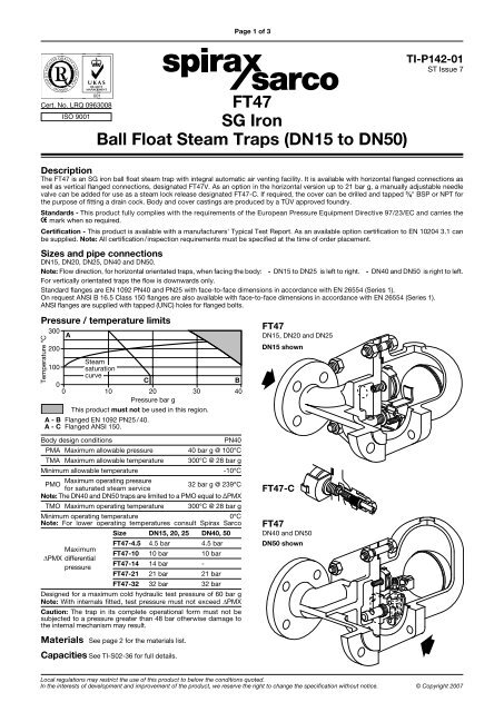
Description<br />
The <strong>FT47</strong> is an <strong>SG</strong> iron ball float steam trap with integral au<strong>to</strong>matic air venting facility. It is available with horizontal flanged connections as<br />
well as vertical flanged connections, designated <strong>FT47</strong>V. As an option in the horizontal version up <strong>to</strong> 21 bar g, a manually adjustable needle<br />
valve can be added for use as a steam lock release designated <strong>FT47</strong>-C. If required, the cover can be drilled and tapped 3 / 8" BSP or NPT for<br />
the purpose of fitting a drain cock. Body and cover castings are produced by a TÜV approved foundry.<br />
Standards - This product fully complies with the requirements of the European Pressure Equipment Directive 97/23/EC and carries the<br />
mark when so required.<br />
Certification - This product is available with a manufacturers' Typical Test Report. As an available option certification <strong>to</strong> EN 10204 3.1 can<br />
be supplied. Note: All certification/inspection requirements must be specified at the time of order placement.<br />
Sizes and pipe connections<br />
<strong>DN15</strong>, DN20, DN25, DN40 and <strong>DN50</strong>.<br />
Note: Flow direction, for horizontal orientated traps, when facing the body: - <strong>DN15</strong> <strong>to</strong> DN25 is left <strong>to</strong> right. - DN40 and <strong>DN50</strong> is right <strong>to</strong> left.<br />
For vertically orientated traps the flow is downwards only.<br />
Standard flanges are EN 1092 PN40 and PN25 with face-<strong>to</strong>-face dimensions in accordance with EN 26554 (Series 1).<br />
On request ANSI B 16.5 Class 150 flanges are also available with face-<strong>to</strong>-face dimensions in accordance with EN 26554 (Series 1).<br />
ANSI flanges are supplied with tapped (UNC) holes for flanged bolts.<br />
Pressure / temperature limits<br />
Temperature °C<br />
<br />
<br />
A<br />
<strong>Steam</strong><br />
saturation<br />
curve<br />
C<br />
B<br />
<br />
<br />
Pressure bar g<br />
This product must not be used in this region.<br />
A - B Flanged EN 1092 PN25 / 40.<br />
A - C Flanged ANSI 150.<br />
Body design conditions<br />
PN40<br />
PMA Maximum allowable pressure 40 bar g @ 100°C<br />
TMA Maximum allowable temperature<br />
Minimum allowable temperature<br />
300°C @ 28 bar g<br />
-10°C<br />
<strong>FT47</strong><br />
<strong>DN15</strong>, DN20 and DN25<br />
<strong>DN15</strong> shown<br />
PMO Maximum operating pressure 32 bar g @ 239°C<br />
for saturated steam service<br />
Note: The DN40 and <strong>DN50</strong> traps are limited <strong>to</strong> a PMO equal <strong>to</strong> ∆PMX<br />
TMO Maximum operating temperature<br />
300°C @ 28 bar g<br />
Minimum operating temperature 0°C<br />
Note: For lower operating temperatures consult <strong>Spirax</strong> <strong>Sarco</strong><br />
Maximum<br />
PMX differential<br />
pressure<br />
Size <strong>DN15</strong>, 20, 25 DN40, 50<br />
<strong>FT47</strong>-4.5 4.5 bar 4.5 bar<br />
<strong>FT47</strong>-10 10 bar 10 bar<br />
<strong>FT47</strong>-14 14 bar -<br />
<strong>FT47</strong>-21 21 bar 21 bar<br />
<strong>FT47</strong>-32 32 bar 32 bar<br />
Designed for a maximum cold hydraulic test pressure of 60 bar g<br />
Note: With internals fitted, test pressure must not exceed PMX<br />
Caution: The trap in its complete operational form must not be<br />
subjected <strong>to</strong> a pressure greater than 48 bar otherwise damage <strong>to</strong><br />
the internal mechanism may result.<br />
<strong>FT47</strong>-C<br />
<strong>FT47</strong><br />
DN40 and <strong>DN50</strong><br />
<strong>DN50</strong> shown<br />
Materials See page 2 for the materials list.<br />
Capacities See TI-S02-36 for full details.<br />
Local regulations may restrict the use of this product <strong>to</strong> below the conditions quoted.<br />
In the interests of development and improvement of the product, we reserve the right <strong>to</strong> change the specification without notice. © Copyright 2007
Page 2 of 3<br />
<strong>FT47</strong><br />
<strong>DN15</strong>, DN20 and DN25<br />
<strong>DN15</strong> shown<br />
2 1 3 18 17 8 4<br />
10<br />
11<br />
2 1 3 18 17 8 4<br />
9 12 6 5 7<br />
<strong>FT47</strong>-C<br />
17 18 20 21 19<br />
<strong>FT47</strong><br />
DN40 and <strong>DN50</strong><br />
<strong>DN50</strong> shown<br />
7<br />
6 26 5<br />
Materials<br />
No. Part<br />
Material<br />
1 Body <strong>SG</strong> iron DIN 1693 GGG 40.3<br />
2<br />
Cover stud Steel DIN 17420 21 Cr Mo V57<br />
Cover nuts Steel DIN 17420 24 Cr Mo 5<br />
3 Cover gasket Reinforced exfoliated graphite<br />
4 Cover <strong>SG</strong> iron DIN 1693 GGG 40.3<br />
5<br />
6<br />
7<br />
Valve seat <strong>DN15</strong>, DN20 and DN25 Stainless steel BS 970 431 S29<br />
Main valve assembly with erosion deflec<strong>to</strong>r DN40 and <strong>DN50</strong> Stainless steel<br />
BS 3146 Pt2 ANC2<br />
BS 970 416 S37<br />
Valve seat gasket <strong>DN15</strong>, DN20 and DN25 Stainless steel BS 1449 304 S11<br />
Main valve assembly gasket DN40 and <strong>DN50</strong> Reinforced exfoliated graphite<br />
Pivot frame assembly set screws <strong>DN15</strong>, DN20 and DN25 Stainless steel BS 4183 18/8<br />
Main valve assembly<br />
Bolts DN40 Stainless steel BS 970 302 S25<br />
Studs and nuts <strong>DN50</strong> Stainless steel BS 970 431 S29<br />
8 <strong>Ball</strong> float and lever Stainless steel BS 1449 304 S16<br />
9 Support frame <strong>DN15</strong>, DN20 and DN25 Stainless steel BS 1449 304 S16<br />
10 Pivot frame <strong>DN15</strong>, DN20 and DN25 Stainless steel BS 1449 304 S16<br />
11 Pivot pin <strong>DN15</strong>, DN20 and DN25 Stainless steel<br />
12 Erosion deflec<strong>to</strong>r <strong>DN15</strong>, DN20 and DN25 for horizontal installations only Stainless steel BS 970 431 S29<br />
17 Air vent assembly Stainless steel<br />
18 Air vent seat gasket Stainless steel BS 1449 409 S19<br />
19 SLR assembly Stainless steel BS 970 303 S31<br />
20 SLR gasket Steel BS 1449 CS 4<br />
21 SLR seal Graphite<br />
26 Inlet plate DN40 and <strong>DN50</strong> for horizontal installations only Stainless steel BS 1449 304 S16<br />
<strong>FT47</strong> <strong>SG</strong> <strong>Iron</strong> <strong>Ball</strong> <strong>Float</strong> <strong>Steam</strong> <strong>Traps</strong> (<strong>DN15</strong> <strong>to</strong> <strong>DN50</strong>)<br />
TI-P142-01 ST Issue 7
Page 3 of 3<br />
<strong>FT47</strong><br />
<strong>DN15</strong> and DN20<br />
<strong>FT47</strong><br />
DN25, DN40 and <strong>DN50</strong><br />
<strong>FT47</strong>V<br />
<strong>DN15</strong> and DN20<br />
<strong>FT47</strong>V<br />
DN25, DN40 and <strong>DN50</strong><br />
A<br />
B<br />
C<br />
Dimensions/weights (approximate) in mm and kg<br />
Size A B C D E F Weight<br />
<strong>DN15</strong> 150 80 80 215 120 155 10.8<br />
DN20 150 80 80 225 120 165 10.8<br />
DN25 160 115 85 276 170 215 15.0<br />
DN40 230 130 115 326 200 200 33.0<br />
<strong>DN50</strong> 230 141 123 332 200 236 34.0<br />
Face-<strong>to</strong>-face dimensions in accordance with EN 26554 (Series 1)<br />
Safety information, installation and maintenance<br />
For full details see the Installation and Maintenance Instructions<br />
(IM-S02-30) supplied with the product.<br />
Installation note:<br />
The <strong>FT47</strong> must be installed with the direction of flow as indicated<br />
on the body, and with the float arm in a horizontal plane so that it<br />
rises and falls vertically.<br />
Disposal<br />
This product is recyclable. No ecological hazard is anticipated with<br />
the disposal of this product, providing due care is taken.<br />
How <strong>to</strong> order<br />
Example: 1 off <strong>Spirax</strong> <strong>Sarco</strong> DN25 <strong>FT47</strong>-14 ball float steam trap,<br />
having an <strong>SG</strong> iron body and cover with thermostatic air vent.<br />
Connections are <strong>to</strong> be flanged <strong>to</strong> EN 1092 PN40.<br />
<strong>Steam</strong> lock<br />
release assembly<br />
F<br />
D<br />
2 Dowel 3<br />
18<br />
E<br />
F<br />
B<br />
C<br />
E<br />
A<br />
Spare parts<br />
The spare parts available are shown in heavy outline. Parts drawn<br />
in broken line are not supplied as spares.<br />
Available spares<br />
Main valve assembly with float<br />
(<strong>DN15</strong>, DN20 and DN25 horizontal traps)*<br />
5, 6, 7, 8, 9, 10, 11<br />
Main valve assembly with integral erosion deflec<strong>to</strong>r (DN40 and 50) **<br />
(specify horizontal or vertical trap) 5, 6, 7, 12, 26<br />
Main valve assembly with float<br />
(<strong>DN15</strong>, DN20 and DN25 vertical traps only)<br />
5, 6, 7, 8, 9, 10, 11<br />
<strong>Ball</strong> float (DN40 and 50) 8<br />
Air vent assembly 17, 18<br />
<strong>Steam</strong> lock release and air vent assembly (<strong>FT47</strong>-C) 17, 18, 19, 20, 21<br />
Complete set of gaskets (packet of 3 sets) 3, 6, 18, 20, 21<br />
* On horizontal traps the erosion deflec<strong>to</strong>r on the <strong>DN15</strong>, DN20<br />
and DN25 is pressed in<strong>to</strong> the body during manufacture and not<br />
available as a spare.<br />
** There is no erosion deflec<strong>to</strong>r on vertical traps in sizes DN40<br />
and <strong>DN50</strong>.<br />
How <strong>to</strong> order spares<br />
Always order spares by using the description given in the column<br />
headed 'Available spares' and state the size and type of trap, including<br />
pressure range and orientation i.e.: horizontal or vertical connections.<br />
Example: 1 - Air vent assembly for a <strong>Spirax</strong> <strong>Sarco</strong> DN20 <strong>FT47</strong>-21<br />
ball float steam trap, with horizontal connections.<br />
Air vent assembly<br />
17<br />
A<br />
19<br />
20<br />
2<br />
6 5 10<br />
7<br />
8<br />
11 9<br />
Main valve assembly with float<br />
(<strong>DN15</strong>, DN20 and DN25)<br />
Recommended tightening <strong>to</strong>rques<br />
or<br />
Item Size<br />
N m<br />
mm<br />
<strong>DN15</strong>, 20 and 25 17 A/F M10 x 60 19 - 22<br />
2 DN40 19 A/F M16 x 85 60 - 66<br />
<strong>DN50</strong> 24 A/F M16 x 85 80 - 88<br />
5 <strong>DN15</strong>, 20 and 25 17 A/F 50 - 55<br />
<strong>DN15</strong>, 20 and 25 M5 x 20 2.5 - 2.8<br />
7 DN40 10 A/F M6 x 20 10 - 12<br />
<strong>DN50</strong> 13 A/F M8 x 20 20 - 24<br />
17 17 A/F 50 - 55<br />
19 22 A/F 50 - 55<br />
12 6 26 5 7 8<br />
Main valve assembly<br />
(DN40 and <strong>DN50</strong>)<br />
(horizontal assembly shown)<br />
<strong>FT47</strong> <strong>SG</strong> <strong>Iron</strong> <strong>Ball</strong> <strong>Float</strong> <strong>Steam</strong> <strong>Traps</strong> (<strong>DN15</strong> <strong>to</strong> <strong>DN50</strong>) TI-P142-01 ST Issue 7