
Create successful ePaper yourself
Turn your PDF publications into a flip-book with our unique Google optimized e-Paper software.
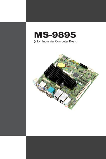
<strong>MS</strong>-<strong>9895</strong><br />
(v1.x) Industrial Computer Board
▍ Preface<br />
Copyright Notice<br />
The material in this document is our intellectual property. We take every<br />
care in the preparation of this document, but no guarantee is given as to the<br />
correctness of its contents. Our products are under continual improvement<br />
and we reserve the right to make changes without notice.<br />
Trademarks<br />
All trademarks are the properties of their respective owners.<br />
■<br />
■<br />
■<br />
■<br />
■<br />
■<br />
■<br />
■<br />
NVIDIA ® is registered trademark of NVIDIA Corporation.<br />
ATI ® is registered trademark of ATI Technologies, Inc.<br />
AMD ® is registered trademarks of AMD Corporation.<br />
Intel ® is registered trademarks of Intel Corporation.<br />
Windows ® is registered trademarks of Microsoft Corporation.<br />
AMI ® is registered trademark of Advanced Micro Devices, Inc.<br />
Award ® is a registered trademark of Phoenix Technologies Ltd.<br />
Realtek ® is registered trademark of Realtek Semiconductor Corporation.<br />
Revision History<br />
Revision Revision History Date<br />
V1.2 For PCB v1.x 2012/11<br />
ii
<strong>MS</strong>-<strong>9895</strong><br />
Safety Instructions<br />
■<br />
■<br />
■<br />
■<br />
■<br />
■<br />
■<br />
■<br />
■<br />
■<br />
■<br />
■<br />
Always read the safety instructions carefully.<br />
Keep this User’s Manual for future reference.<br />
Keep this equipment away from humidity.<br />
Lay this equipment on a reliable flat surface before setting it up.<br />
The openings on the enclosure are for air convection hence protects the<br />
equipment from overheating. DO NOT COVER THE OPENINGS.<br />
Make sure the voltage of the power source and adjust properly 110/220V<br />
before connecting the equipment to the power inlet.<br />
Place the power cord such a way that people can not step on it. Do not<br />
place anything over the power cord.<br />
Always Unplug the Power Cord before inserting any add-on card or module.<br />
All cautions and warnings on the equipment should be noted.<br />
Never pour any liquid into the opening that could damage or cause electrical<br />
shock.<br />
If any of the following situations arises, get the equipment checked by service<br />
personnel:<br />
◯<br />
◯<br />
◯<br />
◯<br />
◯<br />
◯<br />
The power cord or plug is damaged.<br />
Liquid has penetrated into the equipment.<br />
The equipment has been exposed to moisture.<br />
The equipment does not work well or you can not get it work according<br />
to User’s Manual.<br />
The equipment has dropped and damaged.<br />
The equipment has obvious sign of breakage.<br />
DO NOT LEAVE THIS EQUIPMENT IN AN ENVIRONMENT UNCONDI-<br />
TIONED, STORAGE TEMPERATURE ABOVE 60 o C (140 o F), IT MAY DAM-<br />
AGE THE EQUIPMENT.<br />
CAUTION: Danger of explosion if battery is incorrectly replaced. Replace only with<br />
the same or equivalent type recommended by the manufacturer.<br />
警 告 使 用 者 :<br />
這 是 甲 類 資 訊 產 品 , 在 居 住 的 環 境 中 使 用 時 , 可 能 會 造 成 無 線 電 干 擾 , 在 這 種 情<br />
況 下 , 使 用 者 會 被 要 求 採 取 某 些 適 當 的 對 策 。<br />
廢 電 池 請 回 收<br />
For better environmental protection, waste batteries should be<br />
collected separately for recycling or special disposal.<br />
iii
▍ Preface<br />
CE Conformity<br />
Hereby, we declare that this device is in compliance with the<br />
essential safety requirements and other relevant provisions set<br />
out in the European Directive.<br />
FCC-B Radio Frequency Interference<br />
Statement<br />
This equipment has been tested and found to comply with the<br />
limits for a Class B digital device, pursuant to Part 15 of the<br />
FCC Rules. These limits are designed to provide reasonable<br />
protection against harmful interference in a residential installation. This equipment<br />
generates, uses and can radiate radio frequency energy and, if not installed<br />
and used in accordance with the instruction manual, may cause harmful<br />
interference to radio communications. However, there is no guarantee that interference<br />
will not occur in a particular installation. If this equipment does cause<br />
harmful interference to radio or television reception, which can be determined<br />
by turning the equipment off and on, the user is encouraged to try to correct the<br />
interference by one or more of the measures listed below:<br />
Reorient or relocate the receiving antenna.<br />
Increase the separation between the equipment and receiver.<br />
Connect the equipment into an outlet on a circuit different from that to<br />
which the receiver is connected.<br />
Notice 1<br />
Consult the dealer or an experienced radio/television technician for help.<br />
The changes or modifications not expressly approved by the party responsible<br />
for compliance could void the user’s authority to operate the equipment.<br />
Notice 2<br />
Shielded interface cables and AC power cord, if any, must be used in order to<br />
comply with the emission limits.<br />
VOIR LA NOTICE D’INSTALLATION AVANT DE RACCORDER AU RESEAU.<br />
This device complies with Part 15 of the FCC Rules. Operation is subject to the<br />
following two conditions:<br />
1.<br />
2.<br />
■<br />
■<br />
■<br />
■<br />
this device may not cause harmful interference, and<br />
this device must accept any interference received, including interference<br />
that may cause undesired operation.<br />
iv
<strong>MS</strong>-<strong>9895</strong><br />
WEEE Statement<br />
ENGLISH<br />
Under the European Union (“EU”) Directive on Waste Electrical and Electronic Equipment,<br />
Directive 2002/96/EC, which takes effect on August 13, 2005, products of “electrical and<br />
electronic equipment” cannot be discarded as municipal waste anymore and manufacturers<br />
of covered electronic equipment will be obligated to take back such products at the<br />
end of their useful life.<br />
DEUTSCH<br />
Gemäß der Richtlinie 2002/96/EG über Elektro- und Elektronik-Altgeräte dürfen Elektround<br />
Elektronik-Altgeräte nicht mehr als kommunale Abfälle entsorgt werden. Wir haben<br />
europaweit verschiedene Sammel- und Recyclingunternehmen beauftragt, die in die Europäische<br />
Union in Verkehr gebrachten Produkte, am Ende seines Lebenszyklus zurückzunehmen.<br />
Bitte entsorgen Sie dieses Produkt zum gegebenen Zeitpunkt ausschliesslich<br />
an einer lokalen Altgerätesammelstelle in Ihrer Nähe.<br />
FRANÇAIS<br />
Au sujet de la directive européenne (EU) relative aux déchets des équipement électriques<br />
et électroniques, directive 2002/96/EC, prenant effet le 13 août 2005, que les produits électriques<br />
et électroniques ne peuvent être déposés dans les décharges ou tout simplement<br />
mis à la poubelle. Les fabricants de ces équipements seront obligés de récupérer certains<br />
produits en fin de vie. Par conséquent vous pouvez retourner localement ces matériels<br />
dans les points de collecte.<br />
РУССКИЙ<br />
В соответствии с директивой Европейского Союза (ЕС) по предотвращению<br />
загрязнения окружающей среды использованным электрическим и электронным<br />
оборудованием (директива WEEE 2002/96/EC), вступающей в силу 13 августа 2005<br />
года, изделия, относящиеся к электрическому и электронному оборудованию, не могут<br />
рассматриваться как бытовой мусор, поэтому производители вышеперечисленного<br />
электронного оборудования обязаны принимать его для переработки по окончании<br />
срока службы.<br />
ESPAÑOL<br />
Bajo la directiva 2002/96/EC de la Unión Europea en materia de desechos y/o equipos<br />
electrónicos, con fecha de rigor desde el 13 de agosto de 2005, los productos clasificados<br />
como “eléctricos y equipos electrónicos” no pueden ser depositados en los contenedores<br />
habituales de su municipio, los fabricantes de equipos electrónicos, están obligados a<br />
hacerse cargo de dichos productos al termino de su período de vida.<br />
NEDERLANDS<br />
De richtlijn van de Europese Unie (EU) met betrekking tot Vervuiling van Electrische en<br />
Electronische producten (2002/96/EC), die op 13 Augustus 2005 in zal gaan kunnen niet
▍ Preface<br />
meer beschouwd worden als vervuiling. Fabrikanten van dit soort producten worden<br />
verplicht om producten retour te nemen aan het eind van hun levenscyclus.<br />
SRPSKI<br />
Po Direktivi Evropske unije (“EU”) o odbačenoj ekektronskoj i električnoj opremi, Direktiva<br />
2002/96/EC, koja stupa na snagu od 13. Avgusta 2005, proizvodi koji spadaju<br />
pod “elektronsku i električnu opremu” ne mogu više biti odbačeni kao običan otpad i<br />
proizvođači ove opreme biće prinuđeni da uzmu natrag ove proizvode na kraju njihovog<br />
uobičajenog veka trajanja.<br />
POLSKI<br />
Zgodnie z Dyrektywą Unii Europejskiej (“UE”) dotyczącą odpadów produktów elektrycznych<br />
i elektronicznych (Dyrektywa 2002/96/EC), która wchodzi w życie 13 sierpnia<br />
2005, tzw. “produkty oraz wyposażenie elektryczne i elektroniczne “ nie mogą być traktowane<br />
jako śmieci komunalne, tak więc producenci tych produktów będą zobowiązani<br />
do odbierania ich w momencie gdy produkt jest wycofywany z użycia.<br />
TÜRKÇE<br />
Avrupa Birliği (AB) Kararnamesi Elektrik ve Elektronik Malzeme Atığı, 2002/96/EC Kararnamesi<br />
altında 13 Ağustos 2005 tarihinden itibaren geçerli olmak üzere, elektrikli ve<br />
elektronik malzemeler diğer atıklar gibi çöpe atılamayacak ve bu elektonik cihazların<br />
üreticileri, cihazların kullanım süreleri bittikten sonra ürünleri geri toplamakla yükümlü<br />
olacaktır.<br />
ČESKY<br />
Podle směrnice Evropské unie (“EU”) o likvidaci elektrických a elektronických výrobků<br />
2002/96/EC platné od 13. srpna 2005 je zakázáno likvidovat “elektrické a elektronické<br />
výrobky” v běžném komunálním odpadu a výrobci elektronických výrobků, na které se<br />
tato směrnice vztahuje, budou povinni odebírat takové výrobky zpět po skončení jejich<br />
životnosti.<br />
MAGYAR<br />
Az Európai Unió („EU”) 2005. augusztus 13-án hatályba lépő, az elektromos és elektronikus<br />
berendezések hulladékairól szóló 2002/96/EK irányelve szerint az elektromos és<br />
elektronikus berendezések többé nem kezelhetőek lakossági hulladékként, és az ilyen<br />
elektronikus berendezések gyártói kötelessé válnak az ilyen termékek visszavételére<br />
azok hasznos élettartama végén.<br />
ITALIANO<br />
In base alla Direttiva dell’Unione Europea (EU) sullo Smaltimento dei Materiali Elettrici<br />
ed Elettronici, Direttiva 2002/96/EC in vigore dal 13 Agosto 2005, prodotti appartenenti<br />
alla categoria dei Materiali Elettrici ed Elettronici non possono più essere eliminati come<br />
rifiuti municipali: i produttori di detti materiali saranno obbligati a ritirare ogni prodotto alla<br />
fine del suo ciclo di vita.<br />
vi
<strong>MS</strong>-<strong>9895</strong><br />
Contents<br />
Copyright Notice .................................................................................ii<br />
Trademarks .........................................................................................ii<br />
Revision History ..................................................................................ii<br />
Safety Instructions ............................................................................. iii<br />
CE Conformity ....................................................................................iv<br />
FCC-B Radio Frequency Interference Statement ..............................iv<br />
WEEE Statement ................................................................................v<br />
1. Overview............................................................................................. 1-1<br />
Mainboard Specifications ................................................................ 1-2<br />
Mainboard Layout ........................................................................... 1-4<br />
2. Hardware Setup ................................................................................. 2-1<br />
Quick Components Guide ............................................................... 2-2<br />
Memory ........................................................................................... 2-3<br />
Power Supply .................................................................................. 2-4<br />
Back Panel I/O ................................................................................ 2-5<br />
Connector ....................................................................................... 2-8<br />
Jumper .......................................................................................... 2-15<br />
Slot ................................................................................................ 2-17<br />
3. BIOS Setup ......................................................................................... 3-1<br />
Entering Setup ................................................................................ 3-2<br />
The Menu Bar ................................................................................. 3-4<br />
Main ................................................................................................ 3-5<br />
Advanced ........................................................................................ 3-7<br />
Boot ............................................................................................... 3-14<br />
Security ......................................................................................... 3-15<br />
Chipset .......................................................................................... 3-17<br />
Power ............................................................................................ 3-18<br />
Save & Exit ................................................................................... 3-20<br />
vii
Chapter 1<br />
Overview<br />
Thank you for choosing the <strong>MS</strong>-<strong>9895</strong>, an excellent industrial<br />
computer board.<br />
Based on the innovative Intel ® NM10 chipset for optimal<br />
system efficiency, the <strong>MS</strong>-<strong>9895</strong> accommodates<br />
the Intel ® Cedarview-M / Cedarview-D processor<br />
and supports up to 1 DDR3 1066MHz Non-ECC SO-<br />
DIMM slot to provide the maximum of 4GB memory<br />
capacity.<br />
In the advanced-level and mid-range market segment,<br />
the <strong>MS</strong>-<strong>9895</strong> provides a high-performance solution for<br />
today’s front-end and general purpose workstation, as<br />
well as in the future.
▍ Overview<br />
Mainboard Specifications<br />
CPU<br />
Chipset<br />
Memory<br />
LAN<br />
Storage<br />
Audio<br />
Graphics<br />
Back<br />
Panel I/O<br />
■ Intel Cedarview-D D2550 / Cedarview-M N2800 / Cedarview-M<br />
N2600 processor<br />
■ North Bridge: integrated with CPU<br />
■ South Bridge: Intel NM10 chipset<br />
■ 1 DDR3 1066MHz Non-ECC SO-DIMM slot<br />
■ Supports the maximum of 4GB for D2550 / N2800<br />
■ Supports the maximum of 2GB for N2600<br />
■ 2 Intel 82574L GbE controllers for D2550/N2800<br />
■ 1 Intel 82574L GbE controller for N2600<br />
■ 2 SATA 3Gb/s ports by Intel NM10 chipset<br />
■ 1 Mini-PCIe slot for mSATA<br />
■ HDA Codec by Realtek ® ALC887 or ALC886<br />
■ Compliant with Azalia 1.0 specs<br />
■ With amplifier<br />
■ Intel 3650 series / 3600 series integrated Graphics<br />
Engine<br />
■ Resolution up to 1920 x 1200 pixels<br />
■ 1 PS/2 mouse port<br />
■ 1 PS/2 keyboard port<br />
■ 1 VGA port<br />
■ 1 DVI-D port<br />
■ 2 serial ports<br />
■ 2 Gigabit LAN jacks<br />
■ 4 USB 2.0 ports for D2550 / N2800<br />
■ 2 USB 2.0 ports for N2600<br />
■ 1 Line-In audio jack<br />
■ 1 Line-Out audio jack<br />
■ 1 Mic-In audio jack<br />
1-2
<strong>MS</strong>-<strong>9895</strong><br />
Onboard<br />
Connectors/<br />
Pinheaders/<br />
Jumpers<br />
Slot<br />
Form Factor<br />
Environmental<br />
■ 2 USB 2.0 pinheaders (4 ports)<br />
■ 1 amplifier pinheader<br />
■ 8 serial port pinheaders for D2550<br />
■ 4 serial port pinheaders for N2800 / N2600<br />
■ 1 GPIO pinheader<br />
■ 2 LVDS connectors<br />
■ 1 front audio pinheader<br />
■ 1 TPM pinheader<br />
■ 1 clear CMOS jumper<br />
■ 1 AT/ATX select jumper<br />
■ 4 serial port power jumpers<br />
■ 2 backlight pinheader & LVDS power jumpers<br />
■ 1 PCI slot (supports -12V)<br />
■ 1 Mini-PCIe slot<br />
■ Mini-ITX: 170mm x 170mm<br />
■ Operating Temperature: 0 o C to 60 o C<br />
■ Storage Temperature: -20 o C to 80 o C<br />
■ Humidity: 0% ~ 90% RH, non-condensing<br />
1-3
▍ Overview<br />
Mainboard Layout<br />
LVDS Power<br />
Jumper<br />
Serial Port<br />
Power Jumper<br />
LVDS<br />
Connector<br />
AT/ATX Jumper<br />
DIMM Slot<br />
DC Power<br />
Connector<br />
Back Panel I/O<br />
Clear CMOS<br />
Jumper<br />
Fan Power<br />
Connector<br />
Front USB<br />
Pinheader<br />
LVDS Power<br />
Jumper<br />
SATA Connector<br />
HDD Power<br />
Connector<br />
Amplifier<br />
Pinheader<br />
Front Panel<br />
Pinheader<br />
Serial Port<br />
Pinheader<br />
TPM Pinheader<br />
Front Audio<br />
Pinheader<br />
GPIO<br />
Pinheader<br />
Serial Port<br />
Power Jumper<br />
PCI Slot<br />
Mouse Port<br />
VGA Port<br />
Serial Port<br />
COM1<br />
LAN Jack<br />
LAN Jack<br />
Line-In Jack<br />
Keyboard<br />
Port<br />
DVI-D Port<br />
Serial Port<br />
COM2<br />
USB 2.0<br />
Port<br />
USB 2.0<br />
Port<br />
Line-Out Jack<br />
Mic-In Jack<br />
1-4
Chapter 2<br />
Hardware Setup<br />
This chapter provides you with the information on<br />
mainboard hardware configurations. Incorrect setting<br />
of jumpers and connectors may damage your mainboard.<br />
Please pay special attention not to connect<br />
these headers in wrong direction. DO NOT adjust any<br />
jumper while the mainboard is powered on.
▍ Hardware Setup<br />
Quick Components Guide<br />
LVDS Power<br />
Jumper,<br />
p. 2-16<br />
Serial Port<br />
Power Jumper,<br />
p. 2-16<br />
LVDS<br />
Connector,<br />
p. 2-13<br />
AT/ATX Jumper,<br />
p. 2-15<br />
DIMM Slot,<br />
p. 2-3<br />
DC Power<br />
Connector,<br />
p. 2-4<br />
Back Panel<br />
I/O, p. 2-5<br />
Clear CMOS<br />
Jumper,<br />
p. 2-15<br />
Fan Power Connector,<br />
p. 2-9<br />
Front USB<br />
Pinheader,<br />
p. 2-11<br />
LVDS Power<br />
Jumper,<br />
p. 2-16<br />
SATA Connector,<br />
p. 2-8<br />
HDD Power Connector,<br />
p. 2-4<br />
Front Audio<br />
Pinheader,<br />
p. 2-10<br />
Amplifier<br />
Pinheader,<br />
p. 2-10<br />
GPIO Pinheader,<br />
p. 2-14<br />
Front Panel<br />
Pinheader,<br />
p. 2-9<br />
Serial Port<br />
Pinheader,<br />
p. 2-12<br />
Serial Port<br />
Power Jumper,<br />
p. 2-16<br />
PCI Slot,<br />
p. 2-17<br />
TPM Pinheader,<br />
p. 2-14<br />
2-2
<strong>MS</strong>-<strong>9895</strong><br />
Memory<br />
▶<br />
1.<br />
2.<br />
3.<br />
Installing Memory Modules<br />
Locate the SO-DIMM slot. Align the notch on the DIMM with the key on<br />
the slot and insert the DIMM into the slot.<br />
Push the DIMM gently downwards until the slot levers click and lock<br />
the DIMM in place.<br />
To uninstall the DIMM, flip the slot levers outwards and the DIMM will<br />
be released instantly.<br />
Important<br />
You can barely see the golden finger if the memory module is properly inserted<br />
in the DIMM slot.<br />
2-3
▍ Hardware Setup<br />
Power Supply<br />
DC Power Connector: JPWR1<br />
This connector provides 12/19/24V DC power input.<br />
1.Ground<br />
2.Ground<br />
3.DC Power<br />
4.DC Power<br />
HDD Power Connector: JHDDPWR1, JHDDPWR2<br />
This connector provides power to SATA hard drives.<br />
4+12V<br />
3.GND<br />
2.GND<br />
1.VCC5<br />
2-4
<strong>MS</strong>-<strong>9895</strong><br />
Back Panel I/O<br />
D2550 / N2800<br />
Mouse Port<br />
VGA Port<br />
Serial Port<br />
COM1<br />
LAN Jack<br />
LAN Jack<br />
Line-In Jack<br />
Keyboard<br />
Port<br />
DVI-D Port<br />
Serial Port<br />
COM2<br />
USB 2.0<br />
Port<br />
USB 2.0<br />
Port<br />
Line-Out Jack<br />
Mic-In Jack<br />
N2600<br />
Mouse Port<br />
VGA Port<br />
Serial Port<br />
COM1<br />
LAN Jack<br />
Line-In Jack<br />
Keyboard<br />
Port<br />
DVI-D Port<br />
Serial Port<br />
COM2<br />
USB 2.0<br />
Port<br />
Line-Out Jack<br />
Mic-In Jack<br />
▶ Mouse/Keyboard Port<br />
The standard PS/2 mouse/keyboard DIN connector is for a PS/2 mouse/<br />
keyboard.<br />
▶ VGA Port<br />
The DB15-pin female connector is provided for monitor.<br />
▶ DVI-D Port<br />
The DVI-D (Digital Visual Interface-Digital) connector allows you to connect<br />
an LCD monitor. It provides a high-speed digital interconnection between<br />
the computer and its display device. To connect an LCD monitor, simply<br />
plug your monitor cable into the DVI connector, and make sure that the<br />
other end of the cable is properly connected to your monitor (refer to your<br />
monitor manual for more information.)<br />
2-5
▍ Hardware Setup<br />
▶ COM1: RS-232/422/485 Serial Port (Optional)<br />
The serial port is a 16550A high speed communications port that sends/<br />
receives 16 bytes FIFOs. You can attach a serial mouse or other serial<br />
devices directly to the connector.<br />
RS-232<br />
PIN SIGNAL DESCRIPTION<br />
1<br />
2<br />
3<br />
4<br />
5<br />
6<br />
7<br />
8<br />
9<br />
DCD<br />
RXD<br />
TXD<br />
DTR<br />
GND<br />
DSR<br />
RTS<br />
CTS<br />
VCC_COM1<br />
Data Carrier Detect<br />
Receive Data<br />
Transmit Data<br />
Data Terminal Ready<br />
Signal Ground<br />
Data Set Ready<br />
Request To Send<br />
Clear To Send<br />
Voltage select setting by jumper<br />
RS-422<br />
PIN SIGNAL DESCRIPTION<br />
1<br />
2<br />
3<br />
4<br />
5<br />
6<br />
7<br />
8<br />
9<br />
422 TXD-<br />
422 RXD+<br />
422 TXD+<br />
422 RXD-<br />
GND<br />
NC<br />
NC<br />
NC<br />
NC<br />
Transmit Data, Negative<br />
Receive Data, Positive<br />
Transmit Data, Positive<br />
Receive Data, Negative<br />
Signal Ground<br />
No Connection<br />
No Connection<br />
No Connection<br />
No Connection<br />
RS-485<br />
PIN SIGNAL DESCRIPTION<br />
1<br />
2<br />
3<br />
4<br />
5<br />
6<br />
7<br />
8<br />
9<br />
485 TXD-<br />
NC<br />
485 TXD+<br />
NC<br />
GND<br />
NC<br />
NC<br />
NC<br />
NC<br />
Transmit Data, Negative<br />
No Connection<br />
Transmit Data, Positive<br />
No Connection<br />
Signal Ground<br />
No Connection<br />
No Connection<br />
No Connection<br />
No Connection<br />
2-6
<strong>MS</strong>-<strong>9895</strong><br />
▶ COM2: RS-232 Serial Port<br />
The serial port is a 16550A high speed communications port that sends/<br />
receives 16 bytes FIFOs. You can attach a serial mouse or other serial<br />
devices directly to the connector.<br />
▶ USB 2.0 Port<br />
The USB 2.0 port is for attaching USB devices such as keyboard, mouse, or<br />
other USB compatible devices. It supports data transfer rate up to 480Mbit/s<br />
(Hi-Speed).<br />
▶ LAN<br />
The standard RJ-45 LAN jack is for connection to the Local Area Network<br />
(LAN). You can connect a network cable to it.<br />
Activity Indicator<br />
Speed Indicator<br />
Left LED<br />
(Active LED)<br />
Right LED<br />
(100M/1000M Speed LED)<br />
LED Color Yellow Green/Orange<br />
10M Cable<br />
Plug-in<br />
100M Cable<br />
Plug-in<br />
1000M Cable<br />
Plug-in<br />
No Transmission Yellow (Lighting) OFF<br />
Transmission Yellow (Blinking) OFF<br />
No Transmission Yellow (Lighting) Green (Lighting)<br />
Transmission Yellow (Blinking) Green (Lighting)<br />
No Transmission Yellow (Lighting) Orange (Lighting)<br />
Transmission Yellow (Blinking) Orange (Lighting)<br />
In S3/S4/S5 Standby State Yellow (Lighting) OFF<br />
▶ Audio Jack<br />
■<br />
■<br />
■<br />
Line-In (Blue) - for external CD player or other audio devices<br />
Line-Out (Green) - for speakers or headphones<br />
Mic-In (Pink) - for microphones<br />
2-7
▍ Hardware Setup<br />
Connector<br />
Serial ATA Connector: SATA1 ~ SATA2<br />
This connector is a high-speed Serial ATA interface port. Each connector<br />
can connect one Serial ATA device.<br />
Important<br />
Please do not fold the Serial ATA cable into a 90-degree angle. Otherwise,<br />
data loss may occur during transmission.<br />
2-8
1.Ground<br />
2.+12V<br />
3.Sensor<br />
<strong>MS</strong>-<strong>9895</strong><br />
Front Panel Pinheader: JFP1<br />
This front panel connector is provided for electrical connection to the front<br />
panel switches & LEDs and is compliant with Intel Front Panel I/O Connectivity<br />
Design Guide.<br />
10.No Pin<br />
8.Power_SW-<br />
6.Power_SW+<br />
4.Power_LED-<br />
2.Power_LED+<br />
9.Reserved<br />
7.Reset_SW+<br />
5.Reset_SW-<br />
3.HDD_LED-<br />
1.HDD_LED+<br />
Fan Power Connector: SYSTEM_FAN1<br />
The fan power connector supports system cooling fan with +12V. When<br />
connecting the wire to the connectors, always note that the red wire is the<br />
positive and should be connected to the +12V; the black wire is Ground and<br />
should be connected to GND. If the mainboard has a System Hardware<br />
Monitor chipset onboard, you must use a specially designed fan with speed<br />
sensor to take advantage of the fan control.<br />
2-9
8.No Pin<br />
6.MIC Detection<br />
4.PRESENCE#<br />
2.Ground<br />
▍ Hardware Setup<br />
2.AMP_L+<br />
Audio Amplifier Pinheader: JAMP1<br />
The JAMP1 is used to connect audio amplifiers to enhance audio performance.<br />
1.AMP_L-<br />
3.AMP_R-<br />
4.AMP_R+<br />
Front Audio Pinheader: JAUD1<br />
This connector allows you to connect the front panel audio and is compliant<br />
with Intel Front Panel I/O Connectivity Design Guide.<br />
10.Head Phone Detection<br />
9.Head Phone L<br />
7.SENSE_SEND<br />
5.Head Phone R<br />
3.MIC R<br />
1.MIC L<br />
2-10
9.No Pin<br />
7.Ground<br />
5.USB0+<br />
3.USB0-<br />
1.VCC<br />
<strong>MS</strong>-<strong>9895</strong><br />
Front USB Pinheader: JUSB1, JUSB2<br />
This connector, compliant with Intel I/O Connectivity Design Guide, is ideal<br />
for connecting high-speed USB interface peripherals such as USB HDD,<br />
digital cameras, MP3 players, printers, modems and the like.<br />
10.NC<br />
8.Ground<br />
6.USB1+<br />
4.USB1-<br />
2.VCC<br />
USB 2.0 Bracket (Optional)<br />
Important<br />
Note that the pins of VCC and GND must be connected correctly to avoid<br />
possible damage. Important<br />
2-11
▍ Hardware Setup<br />
RS-232 Serial Port Pinheader: JCOM1, JCOM3<br />
This connector is a 16550A high speed communications port that sends/<br />
receives 16 bytes FIFOs. You can attach serial devices to it through the<br />
optional serial port bracket.<br />
JCOM1<br />
1.COM_NDCD3<br />
3.COM_NTD3<br />
5.GND<br />
7.COM_NRTS3<br />
9.VCC_COM3<br />
11.COM_NDCD4 12.COM_NRD4<br />
13.COM_NTD4 14.COM_NDTR4<br />
17.COM_NRTS4 18.COM_NCTS4<br />
19.VCC_COM4 20.No Connection<br />
21.COM_NDCD5 22.COM_NRD5<br />
15.GND<br />
2.COM_NRD3<br />
4.COM_NDTR3<br />
6.COM_NDSR3<br />
8.COM_NCTS3<br />
10.No Connection<br />
23.COM_NTD5 24.COM_NDTR5<br />
25.GND 26.COM_NDSR5<br />
27.COM_NRTS5 28.COM_NCTS5<br />
29.VCC_COM5 30.No Connection<br />
31.COM_NDCD6<br />
33.COM_NTD6<br />
35.GND<br />
37.COM_NRTS6<br />
39.VCC_COM6<br />
16.COM_NDSR4<br />
32.COM_NRD6<br />
34.COM_NDTR6<br />
36.COM_NDSR6<br />
38.COM_NRI6<br />
40.No Connection<br />
JCOM3<br />
1.COM_NDCD7<br />
3.COM_NTD7<br />
5.GND<br />
7.COM_NRTS7<br />
9.VCC_COM7<br />
11.COM_NDCD8 12.COM_NRD8<br />
13.COM_NTD8 14.COM_NDTR8<br />
17.COM_NRTS8 18.COM_NCTS8<br />
19.VCC_COM8 20.No Connection<br />
21.COM_NDCD9 22.COM_NRD9<br />
15.GND<br />
2.COM_NRD7<br />
4.COM_NDTR7<br />
6.COM_NDSR7<br />
8.COM_NCTS7<br />
10.No Connection<br />
23.COM_NTD9 24.COM_NDTR9<br />
25.GND 26.COM_NDSR9<br />
27.COM_NRTS9 28.COM_NCTS9<br />
29.VCC_COM9 30.No Connection<br />
31.COM_NDCD10<br />
33.COM_NTD10<br />
35.GND<br />
37.COM_NRTS10<br />
39.VCC_COM10<br />
16.COM_NDSR8<br />
32.COM_NRD10<br />
34.COM_NDTR10<br />
36.COM_NDSR10<br />
38.COM_NRI10<br />
40.No Connection<br />
2-12
<strong>MS</strong>-<strong>9895</strong><br />
LVDS Connector: JLVDS1, JLVDS2<br />
The LVDS (Low Voltage Differential Signal) connector provides a digital interface<br />
typically used with flat panels. After connecting an LVDS interface<br />
flat panel to this connector, be sure to check the panel datasheet and set the<br />
JVDD1 jumper to proper power voltage.<br />
2.+12V<br />
4.+12V<br />
JLVDS2<br />
26.LVDS1_DATA 3 P<br />
6.GND<br />
8.GND<br />
10.LCD_VDD<br />
12.LDDC_DATA<br />
14.LVDS_VDDEN<br />
16.GND<br />
18.LVDS1_DATA0 P<br />
20.LVDS1_DATA1 P<br />
22.LVDS1_DATA 2 P<br />
24.LVDS1_CKP<br />
30.LVDS2_DATA0 P<br />
32.LVDS2_DATA1 P<br />
34.LVDS2_DATA 2 P<br />
36.LVDS2_CKP<br />
38.LVDS2_DATA 3 P<br />
28.GND<br />
1.+12V<br />
3.+12V<br />
5.+12V<br />
40.GND<br />
27.GND<br />
7.+3.3V<br />
9.LCD_VDD<br />
11.LDDC_CLK<br />
13.Backlight Control<br />
15.Backlight Enable<br />
17.LVDS1_DATA0 N<br />
19.LVDS1_DATA1 N<br />
21.LVDS1_DATA 2 N<br />
23.LVDS1_CKN<br />
29.LVDS2_DATA0 N<br />
31.LVDS2_DATA1 N<br />
33.LVDS2_DATA 2 N<br />
35.LVDS2_CKN<br />
25.LVDS1_DATA 3 N<br />
39.GND<br />
37.LVDS2_DATA 3 N<br />
30.GND<br />
28.LVDS_DATA0N<br />
JLVDS1<br />
26.LVDS_DATA0P<br />
24.GND<br />
22.LVDS_DATA1 N<br />
20.LVDS_DATA 18.GND 1 P<br />
16.LVDS_DATA2N<br />
14.LVDS_DATA2P<br />
12.GND<br />
10.LVDS_CKN<br />
8.LVDS_CKP<br />
6.GND<br />
4.LVDS_DATA3N<br />
2.LVDS_DATA3P<br />
29.GND<br />
27.LDDC_CLK<br />
25.LDDC_DATA<br />
23.GND<br />
21.VCC3<br />
19.LCD_VDD<br />
17.LCD_VDD<br />
13.GND<br />
11.GND<br />
9.NC<br />
7.LBKLT_CTL_C<br />
5.LBKLT_EN_C<br />
15.GND<br />
3.+12V<br />
1.+12V<br />
2-13
▍ Hardware Setup<br />
GPIO Connector: J1<br />
This connector is provided for the General-Purpose Input/Output (GPIO)<br />
peripheral module.<br />
10.N_GPI0<br />
8.N_GPI1<br />
6.N_GPI2<br />
4.N_GPI3<br />
2.VCC5<br />
9.N_GPO0<br />
7.N_GPO1<br />
5.N_GPO2<br />
3.N_GPO3<br />
1.GND<br />
TPM Module Pinheader: JTPM1<br />
This connector connects to a TPM (Trusted Platform Module) module (optional).<br />
Please refer to the TPM security platform manual for more details<br />
and usages.<br />
14.Ground<br />
12.Ground<br />
2.3V Standby power 1.LPC Clock<br />
10.No Pin<br />
8.5V Power<br />
6.Serial IRQ<br />
4.3.3V Power<br />
13.LPC Frame<br />
11.LPC address & data pin3<br />
9.LPC address & data pin2<br />
7.LPC address & data pin1<br />
5.LPC address & data pin0<br />
3.LPC Reset<br />
2-14
<strong>MS</strong>-<strong>9895</strong><br />
Jumper<br />
Clear CMOS Jumper: JBAT1<br />
There is a CMOS RAM onboard that has a power supply from an external<br />
battery to keep the data of system configuration. With the CMOS RAM, the<br />
system can automatically boot OS every time it is turned on. If you want to<br />
clear the system configuration, set the jumper to clear data.<br />
1<br />
1 1<br />
JBAT1<br />
Normal<br />
Clear CMOS<br />
Important<br />
You can clear CMOS by shorting 2-3 pin while the system is off. Then return<br />
to 1-2 pin position. Avoid clearing the CMOS while the system is on; it will<br />
damage the mainboard.<br />
AT/ATX Select Jumper: JAT1<br />
This jumper allows users to select between AT and ATX power.<br />
JAT1<br />
1<br />
AT<br />
1 1<br />
ATX<br />
2-15
▍ Hardware Setup<br />
Serial Port Power Jumper: JCOMP1, JCOMP2,<br />
JCOMP3, JCOMP4<br />
These jumpers specify the operation voltage of the onboard serial ports.<br />
1<br />
JCOMP1/2<br />
(for COM1/2)<br />
1 1<br />
+5V +12V<br />
1<br />
1 1<br />
JCOMP3/4<br />
(for JCOM1)<br />
+5V +12V<br />
Backlight Pinheader & LVDS Power Jumper: JVDD1,<br />
JVDD2<br />
The backlight connector is provided for LCD backlight options while the<br />
LVDS power jumper allows users to select the operation voltage of the<br />
LVDS flat panel.<br />
JVDD1/2<br />
LVDS Power Jumper<br />
1 2 10<br />
9<br />
Backlight Connector<br />
PIN<br />
1<br />
3<br />
5<br />
7<br />
9<br />
SIGNAL<br />
VCC5<br />
L_BKLTCTL<br />
INV_ON<br />
GND<br />
+12V<br />
1 2 10 9 1 2 10 9 1 2 10 9 1 2 10<br />
9<br />
VCC5<br />
VCC3<br />
VCC3<br />
+12V<br />
2-16
<strong>MS</strong>-<strong>9895</strong><br />
Slot<br />
Mini-PCIe (Peripheral Component Interconnect Express)<br />
Slot<br />
The Mini-PCIe slot is provided for wireless LAN card, TV tuner card, Robson<br />
NAND Flash card and mSATA devices.<br />
PCI (Peripheral Component Interconnect) Slot<br />
The PCI slot supports PCI interface expansion cards.<br />
Important<br />
When adding or removing expansion cards, make sure that you unplug the<br />
power supply first. Meanwhile, read the documentation for the expansion<br />
card to configure any necessary hardware or software settings for the expansion<br />
card, such as jumpers, switches or BIOS configuration.<br />
2-17
Chapter 3<br />
BIOS Setup<br />
This chapter provides information on the BIOS Setup<br />
program and allows you to configure the system for<br />
optimum use.<br />
You may need to run the Setup program when:<br />
■ An error message appears on the screen<br />
during the system booting up, and requests<br />
you to run SETUP.<br />
■ You want to change the default settings for<br />
customized features.
▍ BIOS Setup<br />
Entering Setup<br />
Power on the computer and the system will start POST (Power On Self Test)<br />
process. When the message below appears on the screen, press <br />
key to enter Setup.<br />
Press DEL to enter SETUP<br />
If the message disappears before you respond and you still wish to enter<br />
Setup, restart the system by turning it OFF and On or pressing the RESET<br />
button. You may also restart the system by simultaneously pressing ,<br />
, and keys.<br />
Important<br />
The items under each BIOS category described in this chapter are under<br />
continuous update for better system performance. Therefore, the description<br />
may be slightly different from the latest BIOS and should be held for<br />
reference only.<br />
3-2
<strong>MS</strong>-<strong>9895</strong><br />
Control Keys<br />
← → Select Screen<br />
↑ ↓ Select Item<br />
Enter Select<br />
+ - Change Option<br />
F1 General Help<br />
F7 Previous Values<br />
F9 Optimized Defaults<br />
F10 Save & Exit<br />
Esc Exit<br />
Getting Help<br />
After entering the Setup menu, the first menu you will see is the Main<br />
Menu.<br />
Main Menu<br />
The main menu lists the setup functions you can make changes to. You can<br />
use the arrow keys ( ↑↓ ) to select the item. The on-line description of the<br />
highlighted setup function is displayed at the bottom of the screen.<br />
Sub-Menu<br />
If you find a right pointer symbol appears to the left of certain fields that<br />
means a sub-menu can be launched from this field. A sub-menu contains<br />
additional options for a field parameter. You can use arrow keys ( ↑↓ ) to<br />
highlight the field and press to call up the sub-menu. Then you can<br />
use the control keys to enter values and move from field to field within a<br />
sub-menu. If you want to return to the main menu, just press the .<br />
General Help <br />
The BIOS setup program provides a General Help screen. You can call up<br />
this screen from any menu by simply pressing . The Help screen lists<br />
the appropriate keys to use and the possible selections for the highlighted<br />
item. Press to exit the Help screen.<br />
3-3
▍ BIOS Setup<br />
The Menu Bar<br />
▶ Main<br />
Use this menu for basic system configurations, such as time, date, etc.<br />
▶ Advanced<br />
Use this menu to set up the items of special enhanced features.<br />
▶ Boot<br />
Use this menu to specify the priority of boot devices.<br />
▶ Security<br />
Use this menu to set supervisor and user passwords.<br />
▶ Chipset<br />
This menu controls the advanced features of the onboard chipsets.<br />
▶ Power<br />
Use this menu to specify your settings for power management.<br />
▶ Save & Exit<br />
This menu allows you to load the BIOS default values or factory default settings<br />
into the BIOS and exit the BIOS setup utility with or without changes.<br />
3-4
<strong>MS</strong>-<strong>9895</strong><br />
Main<br />
▶ System Date<br />
This setting allows you to set the system date. The date format is ,<br />
.<br />
▶ System Time<br />
This setting allows you to set the system time. The time format is <br />
.<br />
▶ SATA1/ 2<br />
[Type]<br />
Press PgUp/ or PgDn/ to select<br />
[Manual], [None] or [Auto] type. Note that the<br />
specifications of your drive must match with<br />
the drive table. The hard disk will not work<br />
properly if you enter improper information for<br />
this category. If your hard disk drive type is<br />
not matched or listed, you can use [Manual] to<br />
define your own drive type manually.<br />
3-5
▍ BIOS Setup<br />
[LBA/Large<br />
Mode]<br />
[Block<br />
(Multi-Sector<br />
Transfer)]<br />
[PIO Mode]<br />
[DMA Mode]<br />
[S.M.A.R.T.]<br />
[32 Bit Data<br />
Transfer]<br />
Enabling LBA causes Logical Block Addressing<br />
to be used in place of Cylinders, Heads<br />
and Sectors<br />
Any selection except Disabled determines the<br />
number of sectors transferred per block<br />
Indicates the type of PIO (Programmed<br />
Input/Output)<br />
Indicates the type of Ultra DMA<br />
This allows you to activate the S.M.A.R.T.<br />
(Self-Monitoring Analysis & Reporting Technology)<br />
capability for the hard disks. S.M.A.R.T<br />
is a utility that monitors your disk status to<br />
predict hard disk failure. This gives you an<br />
opportunity to move data from a hard disk that<br />
is going to fail to a safe place before the hard<br />
disk becomes offline.<br />
Enables 32-bit communication between<br />
CPU and IDE controller<br />
▶ SATA Mode Selection<br />
This setting specifies the SATA controller mode.<br />
3-6
<strong>MS</strong>-<strong>9895</strong><br />
Advanced<br />
▶ Quiet Boot<br />
This BIOS feature determines if the BIOS should hide the normal POST<br />
messages with the motherboard or system manufacturer’s full-screen logo.<br />
When it is enabled, the BIOS will display the full-screen logo during the<br />
boot-up sequence, hiding normal POST messages.<br />
When it is disabled, the BIOS will display the normal POST messages, instead<br />
of the full-screen logo.<br />
Please note that enabling this BIOS feature often adds 2-3 seconds of delay<br />
to the booting sequence. This delay ensures that the logo is displayed for a<br />
sufficient amount of time. Therefore, it is recommended that you disable this<br />
BIOS feature for a faster boot-up time.<br />
▶ Bootup NumLock State<br />
This setting is to set the Num Lock status when the system is powered on.<br />
Setting to [On] will turn on the Num Lock key when the system is powered<br />
on. Setting to [Off] will allow users to use the arrow keys on the numeric<br />
keypad.<br />
3-7
▍ BIOS Setup<br />
▶ Option ROM Messages<br />
This item is used to determine the display mode when an optional ROM is<br />
initialized during POST. When set to [Force BIOS], the display mode used<br />
by AMI BIOS is used. Select [Keep Current] if you want to use the display<br />
mode of optional ROM.<br />
▶ CPU Configuration<br />
▶ Hyper-Threading<br />
The processor uses Hyper-Threading technology to increase transaction<br />
rates and reduces end-user response times. The technology treats<br />
the two cores inside the processor as two logical processors that can<br />
execute instructions simultaneously. In this way, the system performance<br />
is highly improved. If you disable the function, the processor will<br />
use only one core to execute the instructions. Please disable this item if<br />
your operating system doesn’t support HT Function, or unreliability and<br />
instability may occur.<br />
▶ Execute Disable Bit<br />
Intel’s Execute Disable Bit functionality can prevent certain classes of<br />
malicious “buffer overflow” attacks when combined with a supporting<br />
operating system. This functionality allows the processor to classify<br />
areas in memory by where application code can execute and where it<br />
cannot. When a malicious worm attempts to insert code in the buffer,<br />
the processor disables code execution, preventing damage or worm<br />
propagation.<br />
3-8
<strong>MS</strong>-<strong>9895</strong><br />
▶ Limit CPUID Maximum<br />
The Max CPUID Value Limit BIOS feature allows you to circumvent<br />
problems with older operating systems that do not support the Intel<br />
Pentium 4 processor with Hyper-Threading Technology. When enabled,<br />
the processor will limit the maximum CPUID input value to 03h when<br />
queried, even if the processor supports a higher CPUID input value.<br />
When disabled, the processor will return the actual maximum CPUID<br />
input value of the processor when queried.<br />
▶ Super IO Configuration<br />
▶ Serial Port 1/ 2/ 3/ 4/ 5/ 6/ 7/ 8/ 9/ 10<br />
This setting enables/disables the specified serial port.<br />
▶ Change Settings<br />
This setting is used to change the address & IRQ settings of the<br />
specified serial port.<br />
▶ Mode Select<br />
Select an operation mode for the serial port 1.<br />
▶ Watch Dog Timer<br />
You can enable the system watch-dog timer, a hardware timer that generates<br />
a reset when the software that it monitors does not respond as<br />
expected each time the watch dog polls it.<br />
3-9
▍ BIOS Setup<br />
▶ Hardware Health Configuration<br />
These items display the current status of all monitored hardware devices/components<br />
such as voltages, temperatures and all fans’ speeds.<br />
▶ Smart Fan Configuration<br />
▶ Smart CPUFAN Function<br />
This setting enables/disables the Smart Fan function. Smart Fan is an<br />
excellent feature which will adjust the CPU/system fan speed automati-<br />
3-10
<strong>MS</strong>-<strong>9895</strong><br />
cally depending on the current CPU/system temperature, avoiding<br />
the overheating to damage your system.<br />
▶ PCI/PCIE Device Configuration<br />
▶ PCI Latency Timer<br />
This item controls how long each PCI device can hold the bus before<br />
another takes over. When set to higher values, every PCI device can<br />
conduct transactions for a longer time and thus improve the effective<br />
PCI bandwidth. For better PCI performance, you should set the item<br />
to higher values.<br />
▶ USB Support<br />
This setting enables/disables support for USB devices.<br />
▶ Legacy USB Support<br />
Set to [Enabled] if you need to use any USB 1.1/2.0 device in the operating<br />
system that does not support or have any USB 1.1/2.0 driver<br />
installed, such as DOS and SCO Unix.<br />
▶ Audio Controller<br />
This setting enables/disables the onboard audio controller.<br />
▶ Launch PXE OpROM, Launch Storage OpROM<br />
This setting enables/disables the initialization of the onboard LAN<br />
Boot ROM during bootup. Selecting [Disabled] will speed up the boot<br />
process.<br />
3-11
▍ BIOS Setup<br />
▶ Serial Port Console Redirection<br />
▶ Console Redirection<br />
Console Redirection operates in host systems that do not have a monitor<br />
and keyboard attached. This setting enables/disables the operation<br />
of console redirection. When set to [Enabled], BIOS redirects and<br />
sends all contents that should be displayed on the screen to the serial<br />
COM port for display on the terminal screen. Besides, all data received<br />
from the serial port is interpreted as keystrokes from a local keyboard.<br />
3-12
<strong>MS</strong>-<strong>9895</strong><br />
▶ GPIO Configuration<br />
▶ GPO0 Data, GPO1 Data, GPO2 Data, GPO3 Data<br />
This setting controls the operation mode of the specified GPIO.<br />
3-13
▍ BIOS Setup<br />
Boot<br />
▶ Boot Option #1 / #2 / #3<br />
This setting allows users to set the sequence of boot devices where BIOS<br />
attempts to load the disk operating system.<br />
▶ Hard Drive BBS Priorities<br />
This setting allows users to set the priority of the specified devices. First<br />
press to enter the sub-menu. Then you may use the arrow keys ( ↑<br />
↓ ) to select the desired device, then press , or , key to move it up/down in the priority list.<br />
3-14
<strong>MS</strong>-<strong>9895</strong><br />
Security<br />
▶ Administrator Password<br />
Administrator Password controls access to the BIOS Setup utility.<br />
▶ User Password<br />
User Password controls access to the system at boot and to the BIOS Setup<br />
utility.<br />
3-15
▍ BIOS Setup<br />
▶ Trusted Computing<br />
▶ TPM Support<br />
This setting controls the Trusted Platform Module (TPM) designed by<br />
the Trusted Computing Group (TCG). TPMs are special-purpose integrated<br />
circuits (ICs) built into a variety of platforms to enable strong<br />
user authentication and machine attestation - essential to prevent inappropriate<br />
access to confidential and sensitive information and to protect<br />
against compromised networks.<br />
3-16
<strong>MS</strong>-<strong>9895</strong><br />
Chipset<br />
▶ IGFX - Boot Type<br />
Use the field to select the type of device you want to use as the boot display<br />
of the system.<br />
▶ LCD Panel Type<br />
This setting allows you to set the resolution of the boot display device.<br />
▶ Fixed Graphics Memory Size<br />
This setting specifies the size of system memory allocated for video memory.<br />
3-17
▍ BIOS Setup<br />
Power<br />
▶ ACPI Sleep State<br />
This item specifies the power saving modes for ACPI function. If your operating<br />
system supports ACPI, you can enter the Standby mode in S3 (STR).<br />
▶ Restore AC Power Loss<br />
This setting specifies whether your system will reboot after a power failure<br />
or interrupt occurs. Available settings are:<br />
[Power Off]<br />
[Power On]<br />
[Last State]<br />
Leaves the computer in the power off state.<br />
Leaves the computer in the power on state.<br />
Restores the system to the previous status before<br />
power failure or interrupt occurred.<br />
▶ Resume On USB from S3/S4<br />
The item allows the activity of the USB device to wake up the system from<br />
S3/S4 sleep state.<br />
3-18
<strong>MS</strong>-<strong>9895</strong><br />
▶ Resume On PCIE/PCI PME<br />
This field specifies whether the system will be awakened from power saving<br />
modes when activity or input signal of onboard PCIE/PCI PME is detected.<br />
▶ Resume On RTC<br />
When [Enabled], your can set the date and time at which the RTC (real-time<br />
clock) alarm awakens the system from suspend mode.<br />
3-19
▍ BIOS Setup<br />
Save & Exit<br />
▶ Save Changes and Exit<br />
Save changes to CMOS and exit the Setup Utility.<br />
▶ Discard Changes and Exit<br />
Abandon all changes and exit the Setup Utility.<br />
▶ Restore Defaults<br />
Restore the factory defaults.<br />
▶ Save as User Defaults<br />
Save all changes as user defaults.<br />
▶ Restore User Defaults<br />
Restore the preset user defaults.<br />
3-20