LBB 1968/00 Plena Feedback Suppressor - WES Components
LBB 1968/00 Plena Feedback Suppressor - WES Components
LBB 1968/00 Plena Feedback Suppressor - WES Components

You also want an ePaper? Increase the reach of your titles
YUMPU automatically turns print PDFs into web optimized ePapers that Google loves.
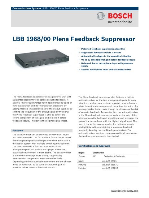
Communications Systems | <strong>LBB</strong> <strong>1968</strong>/<strong>00</strong> <strong>Plena</strong> <strong>Feedback</strong> <strong>Suppressor</strong><br />
<strong>LBB</strong> <strong>1968</strong>/<strong>00</strong> <strong>Plena</strong> <strong>Feedback</strong> <strong>Suppressor</strong><br />
▶ Patented feedback suppression algorithm<br />
▶ Suppresses feedback before it occurs<br />
▶ Automatically adapts to the acoustical situation<br />
▶ Up to 12 dB additional gain before feedback occurs<br />
▶ Balanced line or microphone input with phantom<br />
supply<br />
▶ Second microphone input with automatic mixer<br />
The <strong>Plena</strong> feedback suppressor uses a powerful DSP with<br />
a patented algorithm to suppress acoustic feedback. It<br />
actively filters out unwanted room reverberations using an<br />
echo-cancellation and de-reverberation algorithm. By<br />
adding masked (inaudible) noise to the output signal or by<br />
shifting the frequency of the output signal by five hertz,<br />
the <strong>Plena</strong> feedback suppressor is able to detect the<br />
reverb component of the signal and remove it before<br />
feedback occurs. This leaves the original signal intact.<br />
Functions<br />
The adaptive filter can be switched between fast mode<br />
and accurate mode. The fast mode is for situations where<br />
the microphone position changes over time, such as in a<br />
discussion system with multiple switching microphones.<br />
The accurate mode is for situations with a fixed<br />
microphone position, such as on a pulpit where the<br />
acoustical environment is more stable. The adaptive filter<br />
is allowed to converge more slowly, suppressing<br />
reverberation components even more effectively.<br />
Depending on the acoustical environment and the chosen<br />
mode of operation, up to 12dB of additional gain is<br />
possible before acoustic feedback occurs.<br />
The <strong>Plena</strong> feedback suppressor also features a built-in<br />
automatic mixer for the two microphone inputs. In many<br />
situations, such as on a rostrum, a pulpit or a conference<br />
table, two microphones are used to capture the voice of a<br />
moving speaker better, even though this increases the risk<br />
of acoustic feedback. To counter this, the automatic mixer<br />
in the <strong>Plena</strong> feedback suppressor reduces the gain of the<br />
microphone with the lowest signal input and increases the<br />
gain of the microphone with the highest signal input. This<br />
way, it tracks the moving speaker for optimum speech<br />
intelligibility, while maintaining a maximum feedback<br />
margin by keeping the combined gain constant. The<br />
automatic mixer function remains operational even when<br />
the feedback suppressor is deactivated.<br />
Certifications and Approvals<br />
Region<br />
Certification<br />
Europe CE Declaration of Conformity<br />
Safety acc. to EN 6<strong>00</strong>65<br />
Immunity acc. to EN 55103-2<br />
Emission acc. to EN 55103-1<br />
www.boschsecurity.com
2 | <strong>LBB</strong> <strong>1968</strong>/<strong>00</strong> <strong>Plena</strong> <strong>Feedback</strong> <strong>Suppressor</strong><br />
Installation/Configuration Notes<br />
<strong>LBB</strong> <strong>1968</strong>/<strong>00</strong> back view<br />
Parts Included<br />
Quantity<br />
<strong>Components</strong><br />
1 <strong>LBB</strong> <strong>1968</strong>/<strong>00</strong> <strong>Plena</strong> <strong>Feedback</strong> <strong>Suppressor</strong><br />
1 Power cord<br />
1 Set of 19“ mounting brackets<br />
1 0.5 m XLR cable<br />
1 Installation and User Instructions<br />
1 <strong>Plena</strong> CD<br />
Technical Specifications<br />
Electrical<br />
Mains power supply<br />
Voltage<br />
Inrush current<br />
Max power consumption<br />
Performance<br />
Sample rate (fs)<br />
Frequency response<br />
Distortion<br />
Gain (bypass mode)<br />
Gain (active mode)<br />
S/N<br />
Signal delay<br />
Decorrelator<br />
Mic / line input<br />
Connectors<br />
Max level<br />
Impedance<br />
CMRR<br />
Phantom power<br />
Priority control<br />
230/115 VAC, ±10%, 50/60 Hz<br />
1.5 A @ 230 VAC / 3 A @ 115 VAC<br />
50 VA<br />
32 kHz<br />
125 Hz to 15 kHz<br />
90 dB<br />
25 dB (50 Hz to 20 kHz)<br />
16 V (mic only, switchable)<br />
Loop through of pin 4 and 5 of DIN<br />
Mains power supply<br />
Mic input<br />
Connectors<br />
Max level<br />
Impedance<br />
Phantom power<br />
Priority control<br />
Line input<br />
Connector<br />
Max input level<br />
Impedance<br />
Line output<br />
Connector<br />
Max level<br />
Impedance<br />
Line output<br />
Connector<br />
Max level<br />
Impedance<br />
Mic output<br />
Connector<br />
Max level<br />
Impedance<br />
Priority control<br />
Mechanical<br />
Dimensions (H x W x D)<br />
Weight<br />
Mounting<br />
Color<br />
Environmental<br />
Operating temperature<br />
Storage temperature<br />
1 x<br />
3-pin XLR, 5-pin DIN, balanced<br />
-18 / -30 / -42 dBV<br />
2 kohm<br />
16 V (switchable)<br />
Loop-through of pin 4 and 5 of DIN<br />
1 x<br />
Cinch, unbalanced<br />
18 / 6 / -6 dBV<br />
20 kohm<br />
1 x<br />
3-pin XLR, balanced<br />
18 / 6 / -6 dBV (line in),<br />
6 dBV (mic in)<br />
<strong>Plena</strong> <strong>Feedback</strong> <strong>Suppressor</strong><br />
en<br />
Installation and Operating Manual<br />
<strong>LBB</strong> <strong>1968</strong>
<strong>Plena</strong> <strong>Feedback</strong> <strong>Suppressor</strong> | Installation and Operating Manual | Important safeguards en | 3<br />
Important safeguards<br />
1 Read instructions - All the safety instructions for use<br />
should be read before the system is operated.<br />
2 Retain instructions - The safety instructions and<br />
instructions for use should be retained for future<br />
reference.<br />
3 Heed warnings - All warnings on the unit and in the<br />
operating instructions should be adhered to.<br />
4 Follow instructions - All operating instructions and<br />
instructions for use should be followed.<br />
5 Cleaning - Unplug system units from the mains outlet<br />
before cleaning. Do not use liquid cleaners or aerosol<br />
cleaners. Use a damp cloth for cleaning.<br />
6 Attachments - Do not use attachments not<br />
recommended by the product manufacturer as they may<br />
cause hazards.<br />
7 Water and Moisture - Do not use this unit near water, for<br />
example near a bathtub, washbowl, kitchen sink, or<br />
laundry basket, in a wet basement, near a swimming<br />
pool, in an unprotected outdoor installation or any area<br />
which is classified as a wet location.<br />
8 Accessories - Do not place this unit on an unstable stand,<br />
tripod, bracket or mount. This unit may fall, causing<br />
serious injury to a person and serious damage to the<br />
unit. Use only a stand, tripod, bracket or mount<br />
recommended by the manufacturer, or sold with the<br />
product. Any mounting of the unit should follow the<br />
manufacturer's instructions, and should use a mounting<br />
accessory recommended by the manufacturer. An<br />
appliance and cart combination should be moved with<br />
care. Quick stops, excessive force, and uneven surfaces<br />
may cause the appliance and cart combination to<br />
overturn.<br />
9 Ventilation - Openings in the enclosure, if any, are<br />
provided for ventilation and to ensure reliable operation<br />
of the unit and to protect it from overheating. These<br />
openings must not be blocked or covered. The unit<br />
should not be placed in a built-in installation unless<br />
proper ventilation is provided or the manufacturer's<br />
instructions have been adhered to.<br />
10 Power sources - Units should be operated only from the<br />
type of power source indicated on the marking label. If<br />
you are not sure of the type of power supply you plan to<br />
use, consult your appliance dealer or local power<br />
company. For units intended to operate from battery<br />
power, or other sources, refer to the "Installation and<br />
User Instructions".<br />
11 Grounding or polarisation - This unit may be equipped<br />
with a polarised alternating current line plug (a plug<br />
having one blade wider than the other). This plug will fit<br />
into the power outlet only one way. This is a safety<br />
feature. If you are unable to insert the plug fully into the<br />
outlet, try reversing the plug. If the plug still fails to fit,<br />
contact your electrician to replace your obsolete outlet.<br />
Do not defeat the safety purpose of the polarised plug.<br />
Alternatively, this unit may be equipped with a 3-wire<br />
grounding type plug having a third (grounding) pin.<br />
This plug will only fit into a grounding-type power<br />
outlet. This is a safety feature. If you are unable to insert<br />
the plug into the outlet, contact your electrician to<br />
replace your obsolete outlet. Do not defeat the safety<br />
purpose of the grounding-type lug.<br />
12 Power-Cord Protection - Power supply cords should be<br />
routed so that they are not likely to be walked on or<br />
pinched by items placed upon or against them, paying<br />
particular attention to cords and plugs, convenience<br />
receptacles, and the point where they exit from the<br />
appliance.<br />
13 Overloading - Do not overload outlets and extension<br />
cords as this can result in a risk of fire or electrical shock.<br />
14 Object and Liquid Entry - Never push objects of any<br />
kind into this unit through openings as they may touch<br />
dangerous voltage points or short-out parts that could<br />
result in a fire or electric shock. Never spill liquid of any<br />
kind on the unit.<br />
15 Servicing - Do not attempt to service this unit yourself as<br />
opening or removing covers may expose to dangerous<br />
voltage or other hazards. Refer all servicing to qualified<br />
service personnel.<br />
16 Damage Requiring Service - Unplug the unit from the<br />
outlet and refer servicing to qualified service personnel<br />
under the following conditions:<br />
• When the power-supply cord or plug is damaged.<br />
• If liquid has been spilled, or objects have fallen into<br />
the unit.<br />
• If the unit has been exposed to rain or water.<br />
• If the unit does not operate normally by following<br />
the instructions for use. Adjust only those controls<br />
that are covered by the instructions for use, as an<br />
improper adjustment of other controls may result in<br />
damage and will often require extensive work by a<br />
qualified technician to restore the units to their<br />
normal operation.<br />
• If the unit has been dropped or the unit has been<br />
damaged.<br />
• When the unit exhibits a distinct change in<br />
performance; this indicates a need for service.<br />
17 Replacement Parts - When replacement parts are<br />
required be sure the service technician has used<br />
replacement parts specified by the manufacturer or parts<br />
which have the same characteristics as the original part.<br />
Unauthorised substitutions may result in fire, electric<br />
shock or other hazards.<br />
18 Safety Check - Upon completion of any service or<br />
repairs to the units, ask the service technician to perform<br />
safety checks to determine that the unit is in proper<br />
operating condition.<br />
19 Lightning - For added protection of the units during a<br />
lightning storm, or when it is left unattended and unused<br />
for long periods of time, unplug it from the wall outlet<br />
and disconnect the cable system. This will prevent<br />
damage to the unit due to lightning and power-line<br />
surges.<br />
Bosch Security Systems | 2<strong>00</strong>3-11 | 9922 141 81681en
<strong>Plena</strong> <strong>Feedback</strong> <strong>Suppressor</strong> | Installation and Operating Manual | About this manual en | 4<br />
About this manual<br />
This manual provides all the information required to install and operate the unit.<br />
Conventions<br />
Warning<br />
Follow these instructions to prevent personal injury.<br />
Caution<br />
Follow these instructions to prevent damage to the equipment.<br />
Note<br />
Read these instructions for tips and other useful information.<br />
Safety precautions<br />
Warning<br />
Do not open the unit when it is connected to the mains. The unit contains non-insulated parts, which can<br />
cause electric shock.<br />
Caution<br />
There are no user-serviceable parts inside the unit. Service must be done by qualified personnel.<br />
Bosch Security Systems | 2<strong>00</strong>3-11 | 9922 141 81681en
<strong>Plena</strong> <strong>Feedback</strong> <strong>Suppressor</strong> | Installation and Operating Manual | Table of contents en | 5<br />
Table of contents<br />
Important safeguards..........................................................................................................................................................3<br />
About this manual ..............................................................................................................................................................4<br />
Safety precautions...............................................................................................................................................................4<br />
Table of contents ................................................................................................................................................................5<br />
1 About the equipment ........................................................................................................................................................7<br />
1.1 Functioning (operating principle) ............................................................................................................................7<br />
1.2 Controls and indicators (front) ................................................................................................................................8<br />
1.3 Controls and connections (rear) ..............................................................................................................................9<br />
2 Installation in rack ...........................................................................................................................................................10<br />
3 External settings and connections .................................................................................................................................11<br />
3.1 Connecting the inputs and the outputs .................................................................................................................11<br />
3.1.1 Announcement set-up .......................................................................................................................................11<br />
3.1.2 Live performance set-up and Conference set-up ...........................................................................................12<br />
3.1.3 Presentation set-up and set-up in churches, mosques, houses of worship, etc. ...........................................14<br />
3.1.4 Signal level .........................................................................................................................................................16<br />
3.2 Setting the options switches ...................................................................................................................................17<br />
3.3 Mains connection ....................................................................................................................................................19<br />
4 Operation of the feedback suppressor ..........................................................................................................................20<br />
4.1 Switching ON ..........................................................................................................................................................20<br />
4.2 Calibration ...............................................................................................................................................................21<br />
4.3 General recommendations to prevent feedback .................................................................................................21<br />
5 Technical data ..................................................................................................................................................................22<br />
5.1 Electrical ..................................................................................................................................................................22<br />
5.2 Performance ............................................................................................................................................................22<br />
5.3 Inputs ........................................................................................................................................................................22<br />
5.4 Outputs .....................................................................................................................................................................23<br />
5.5 Controls and indicators ..........................................................................................................................................23<br />
5.6 Environmental conditions ......................................................................................................................................23<br />
5.7 General .....................................................................................................................................................................23<br />
Bosch Security Systems | 2<strong>00</strong>3-11 | 9922 141 81681en
<strong>Plena</strong> <strong>Feedback</strong> <strong>Suppressor</strong> | Installation and Operating Manual | About the equipment<br />
en | 7<br />
1 About the equipment<br />
1.1 Functioning (operating principle)<br />
signal<br />
level<br />
In 1<br />
In 2<br />
+ A<br />
D<br />
D DSP A<br />
C<br />
C<br />
pin 4,5 mic/line pin 4,5<br />
peak signal<br />
bypass<br />
voice tracking<br />
fast/accurate<br />
calibrate<br />
music/speech<br />
bass lift<br />
line level out<br />
mic level out<br />
line level out<br />
figure 1.1: Block diagram<br />
<strong>Feedback</strong> suppression<br />
The <strong>Plena</strong> <strong>Feedback</strong> <strong>Suppressor</strong> uses a powerful DSP with a revolutionary patented algorithm to suppress acoustic<br />
feedback. It eliminates feedback by actively filtering the room reverb that leads to feedback out of the signal, using<br />
an echo cancellation and de-reverberation algorithm. By adding masked (inaudible) noise to the output signal<br />
(Music mode) or by just shifting the frequency of the output signal by 5 Hz (Speech mode) the <strong>Plena</strong> <strong>Feedback</strong><br />
<strong>Suppressor</strong> is able to detect the reverb component of the signal and to remove it before feedback occurs, leaving the<br />
original signal intact.<br />
Auto Mix function<br />
In addition to its feedback suppression function, the <strong>Plena</strong> <strong>Feedback</strong> <strong>Suppressor</strong> also features a built-in automatic<br />
mixer for the two microphone inputs. In many situations two microphones are used to better capture the voice of a<br />
moving speaker, like on a rostrum, pulpit or a conference table, but often this increases the risk of acoustic feedback.<br />
The automatic mixer of the <strong>Plena</strong> <strong>Feedback</strong> <strong>Suppressor</strong>, however, automatically reduces the gain of the microphone<br />
with the lowest signal input and increases the gain of the microphone with the highest signal input. This way it<br />
'tracks' the moving speaker for optimum speech intelligibility, and the maximum feedback margin is maintained by<br />
keeping the summed gain constant. Even if the feedback processor is switched to bypass this automatic mixer is still<br />
operating.<br />
Bosch Security Systems | 2<strong>00</strong>3-11 | 9922 141 81681en
<strong>Plena</strong> <strong>Feedback</strong> <strong>Suppressor</strong> | Installation and Operating Manual | About the equipment<br />
en | 8<br />
1.2 Controls and indicators (front)<br />
<strong>Plena</strong> <strong>Feedback</strong> <strong>Suppressor</strong><br />
Signal<br />
Overload<br />
Processor<br />
Bypass<br />
Present<br />
Voice tracking<br />
Active<br />
Calibrate<br />
Power<br />
1 2 3 4<br />
5 6 7 8 9<br />
figure 1.2: Controls and indicators (front)<br />
1 Power button<br />
2 Input signal overload indicator<br />
The LED lights up to indicate a too high input signal. The input sensitivity can be adjusted with the help of the<br />
signal level switch on the rear (see §1.3).<br />
3 Output signal present indicator<br />
The LED lights up to indicate that the output signal exceeds -40 dBr.<br />
4 Auto Mix indicator<br />
The LED lights up to indicate that the Auto Mix function (see §1.1) is active.<br />
5 Bypass indicator<br />
The LED lights up to indicate that the feedback suppression function is deactivated.<br />
6 <strong>Feedback</strong> suppression active indicator<br />
The LED lights up to indicate that feedback suppression algorithm is active.<br />
7 Bypass switch<br />
8 Calibrate indicator<br />
The LED lights up to indicate a fast calibration cycle after pressing the calibrate button (9).<br />
9 Calibrate button<br />
Upon pressing the calibrate button, random noise at -6 dBr is generated for a few seconds to allow the feedback<br />
suppression algorithm to calibrate quickly.<br />
Bosch Security Systems | 2<strong>00</strong>3-11 | 9922 141 81681en
N663<br />
<strong>Plena</strong> <strong>Feedback</strong> <strong>Suppressor</strong> | Installation and Operating Manual | About the equipment<br />
en | 9<br />
1.3 Controls and connections (rear)<br />
16 15 14 13<br />
Mic 1/Line In<br />
Mic/Line<br />
Mic 2 In<br />
Line<br />
In<br />
On Off<br />
Out<br />
Phantom Mic 1+2<br />
Line Out<br />
High Med. Low<br />
Signal Level<br />
Switch On<br />
Off<br />
1 Music mode<br />
Speech mode<br />
2 Dualinputvoicetracking Single input<br />
115V~ 230V~<br />
Mic1In + Mic2In Mic2/Line In<br />
3 Process with bass lift Process flat<br />
4 Accurate mode Fast mode<br />
<strong>LBB</strong> <strong>1968</strong>/<strong>00</strong> 89<strong>00</strong> 196 8<strong>00</strong>01 Apparatus delivered<br />
connected for 230V-<br />
<strong>Plena</strong> <strong>Feedback</strong> <strong>Suppressor</strong><br />
115/230V~,50/60Hz<br />
S/N.<br />
Rated input<br />
Design & Quality<br />
Power: 50VA<br />
The Netherlands<br />
T5<strong>00</strong>L250V<br />
1234<br />
Warning<br />
This apparatus must be earthed<br />
1 2 3 4 5 6 7 8 9 10<br />
11 12<br />
figure 1.3: Controls and connections (rear)<br />
1 Microphone 1/Line input (XLR/balanced)<br />
2 Microphone 1 input (5-pin DIN/balanced)<br />
3 Mic/Line switch<br />
The Mic/Line switch only affects Microphone 1/Line Input (1)<br />
4 Microphone 2 input (XLR/balanced)<br />
5 Microphone 2 input (5-pin DIN/balanced)<br />
6 Line out (Cinch/unbalanced)<br />
7 Line out (XLR/balanced)<br />
8 Microphone level out (5-pin DIN/balanced). For connection to <strong>Plena</strong> Amplifiers only (see §3.1)<br />
9 Signal level switch (see §3.1)<br />
10 Options switches (see §3.2)<br />
11 Earth connection screw<br />
12 Mains fuse (T5<strong>00</strong> L 250V)<br />
13 Mains connector (3-pole)<br />
14 Mains voltage selection switch<br />
15 Line in (Cinch/unbalanced)<br />
16 Phantom power switch (microphone 1 and 2)<br />
Switch that enables and disables phantom power on Microphone 1/Line input (1 and 2) and Microphone 2 input<br />
(4 and 5). When the line input is selected with the help of the Mic/Line switch (3), phantom power is disabled for<br />
this input.<br />
Bosch Security Systems | 2<strong>00</strong>3-11 | 9922 141 81681en
Power<br />
Signal<br />
Overload<br />
Processor<br />
Bypass<br />
<strong>Plena</strong> <strong>Feedback</strong> <strong>Suppressor</strong> | Installation and Operating Manual | Installation in rack<br />
en | 10<br />
2 Installation in rack<br />
<strong>Plena</strong> <strong>Feedback</strong> <strong>Suppressor</strong><br />
Present Voice tracking<br />
Active Calibrate<br />
figure 2.1: Installation in rack<br />
The feedback suppressor is delivered for tabletop use, but you can mount it in a 19" rack using the brackets supplied<br />
with the unit. In case of rack mounting, you must:<br />
• Remove the 4 feet from the bottom of the unit. Without the feet, the unit is 1U high.<br />
• Ensure that the ambient temperature of the unit in the rack does not exceed 55 °C.<br />
Bosch Security Systems | 2<strong>00</strong>3-11 | 9922 141 81681en
N663<br />
<strong>Plena</strong> <strong>Feedback</strong> <strong>Suppressor</strong> | Installation and Operating Manual | External settings and connections en | 11<br />
3 External settings and connections<br />
3.1 Connecting the inputs and the outputs<br />
Figures 3.1 through 3.5 show some different configuration set-ups.<br />
3.1.1 Announcement set-up<br />
See fig. 3.1.<br />
The <strong>Plena</strong> <strong>Feedback</strong> <strong>Suppressor</strong> is provided with two balanced DIN-inputs (2 and 5) to connect one or two<br />
<strong>LBB</strong>1950 call stations or <strong>LBB</strong>1949 gooseneck microphones. The signal inputs are parallel to the balanced XLRinputs<br />
(1 and 4), and the priority contacts are looped through to pins 4 and 5 of the balanced DIN-output (8).<br />
The output level on the DIN-output (8) is optimized for the priority microphone input level of the <strong>Plena</strong> Mixer<br />
Amplifier range.<br />
• Set the Mic/Line switch (3) to 'Mic'.<br />
• Enable the phantom power supply with the phantom power switch (16).<br />
• If only one call station is used, connect it to the Microphone 1 input (2).<br />
<strong>LBB</strong>1950<br />
<strong>LBB</strong>1950<br />
Mic. In<br />
Mic. In<br />
16<br />
8<br />
<strong>LBB</strong><strong>1968</strong><br />
Mic 1/Line In<br />
Mic/Line<br />
Mic 2 In<br />
Line<br />
In<br />
On Off<br />
Out<br />
Phantom Mic 1+2<br />
Line Out<br />
Switch On<br />
Off<br />
1 Music mode<br />
Speech mode<br />
2 Dualinputvoicetracking Single input<br />
Mic1In + Mic2In Mic2/Line In<br />
3 Process with bass lift Process flat<br />
4 Accurate mode Fast mode<br />
High Med. Low<br />
<strong>LBB</strong> <strong>1968</strong>/<strong>00</strong> 89<strong>00</strong> 196 8<strong>00</strong>01<br />
<strong>Plena</strong> <strong>Feedback</strong> <strong>Suppressor</strong><br />
115/230V~,50/60Hz<br />
S/N<br />
Design & Quality<br />
The Netherlands<br />
Signal Level<br />
1234<br />
Warning<br />
This apparatus must be earthed<br />
115V~ 230V~<br />
Apparatus delivered<br />
connected for 230V-<br />
Rated input<br />
Power: 50VA<br />
T5<strong>00</strong>L250V<br />
1 2 3 4 5<br />
Line Out<br />
<strong>LBB</strong>1914/10<br />
Tel/Emer.<br />
0<br />
L<br />
R<br />
CD Aux Line Out 1V<br />
Inc<br />
Out<br />
In<br />
<strong>LBB</strong>1914/10<br />
89<strong>00</strong> 191 21<strong>00</strong>5<br />
Max. output power 180W<br />
Rated output power 120W<br />
115/240V~,50/60Hz<br />
S/N.<br />
Rated input<br />
power : 4<strong>00</strong>VA<br />
115V<br />
230V<br />
Apparatus delivered<br />
connected for 230V-<br />
0 2<br />
Chime<br />
1 3<br />
4 5<br />
+ GND GND +<br />
3 1 1 2<br />
2<br />
3<br />
Mic/Line<br />
Mic/Line<br />
Call/Mix Zone 1 Zone 2 Call Only Mix Only 24VDCIn<br />
1<strong>00</strong>/70V/ 8Ω0 1<strong>00</strong>/70 V 0 1<strong>00</strong>/70 V 0 1<strong>00</strong>/70 V 0 1<strong>00</strong>/70 V 0<br />
Warning<br />
This apparatus must be earthed<br />
1<br />
2 3 4<br />
figure 3.1: Announcement set-up<br />
Bosch Security Systems | 2<strong>00</strong>3-11 | 9922 141 81681en
N663<br />
<strong>Plena</strong> <strong>Feedback</strong> <strong>Suppressor</strong> | Installation and Operating Manual | External settings and connections en | 12<br />
3.1.2 Live performance set-up and Conference set-up<br />
See fig. 3.2 and fig. 3.3, respectively.<br />
The <strong>Plena</strong> <strong>Feedback</strong> <strong>Suppressor</strong> is provided with one balanced XLR-line input (1) and one unbalanced line input<br />
(15), e.g. to connect a line level source such as an SR-mixer or a DCN Central Control Unit (please refer to the<br />
Operation Manual of your DCN System).<br />
To connect any unit that accepts standard line signals, the unit is provided with one balanced XLR-line output (7)<br />
and one unbalanced line output (6).<br />
• Set the Mic/Line switch (3) to 'Line' to use the balanced line input (1). In this case the phantom power switch (16)<br />
has no function.<br />
16 15<br />
7<br />
<strong>LBB</strong><strong>1968</strong><br />
Mic 1/Line In<br />
Mic/Line<br />
Mic 2 In<br />
Line<br />
In<br />
On Off<br />
Out<br />
Phantom Mic 1+2<br />
Line Out<br />
High Med. Low<br />
Signal Level<br />
Switch On<br />
Off<br />
1 Music mode<br />
Speech mode<br />
2 Dualinputvoicetracking Single input<br />
115V~ 230V~<br />
Mic1In + Mic2In Mic2/Line In<br />
3 Process with bass lift Process flat<br />
4 Accurate mode Fast mode<br />
<strong>LBB</strong> <strong>1968</strong>/<strong>00</strong> 89<strong>00</strong> 196 8<strong>00</strong>01 Apparatus delivered<br />
connected for 230V-<br />
<strong>Plena</strong> <strong>Feedback</strong> <strong>Suppressor</strong><br />
115/230V~,50/60Hz<br />
S/N.<br />
Rated input<br />
Design & Quality<br />
Power: 50VA<br />
The Netherlands<br />
T5<strong>00</strong>L250V<br />
1234<br />
Warning<br />
This apparatus must be earthed<br />
1 3<br />
6<br />
Line In<br />
Line Out<br />
figure 3.2: Live performance set-up<br />
Bosch Security Systems | 2<strong>00</strong>3-11 | 9922 141 81681en
N663<br />
<strong>Plena</strong> <strong>Feedback</strong> <strong>Suppressor</strong> | Installation and Operating Manual | External settings and connections en | 13<br />
Mic 1/Line In<br />
Mic/Line<br />
Mic 2 In<br />
15<br />
Line<br />
In<br />
On Off<br />
Out<br />
Phantom Mic 1+2<br />
Line Out<br />
High Med. Low<br />
Signal Level<br />
Switch On<br />
Off<br />
1 Music mode<br />
Speech mode<br />
2 Dualinputvoicetracking Single input<br />
115V~ 230V~<br />
Mic1In + Mic2In Mic2/Line In<br />
3 Process with bass lift Process flat<br />
4 Accurate mode Fast mode<br />
<strong>LBB</strong> <strong>1968</strong>/<strong>00</strong> 89<strong>00</strong> 196 8<strong>00</strong>01 Apparatus delivered<br />
connected for 230V-<br />
<strong>Plena</strong> <strong>Feedback</strong> <strong>Suppressor</strong><br />
115/230V~,50/60Hz<br />
S/N.<br />
Rated input<br />
Design & Quality<br />
Power: 50VA<br />
The Netherlands<br />
T5<strong>00</strong>L250V<br />
1234<br />
Warning<br />
This apparatus must be earthed<br />
<strong>LBB</strong><strong>1968</strong><br />
3<br />
Line In<br />
6<br />
Line Out<br />
DCN CCU<br />
FCC MARK<br />
CAUTION ATTENTION<br />
REPLACE WITH THE SAME TYPE OF FUSE<br />
UTILISER UN FUSIBLE DE RECHANGE DE MEME TYPE<br />
Warning<br />
This apparatus must be earthed<br />
Port 1<br />
Multi CCU Link Rec. Line Trunk<br />
In<br />
Out In<br />
In<br />
COMMERCIAL<br />
AUDIO EQUIPMENT<br />
LISTED 9R88<br />
Port 2<br />
Out<br />
Out<br />
2A 250V<br />
Symmetrical<br />
Made in Holland<br />
figure 3.3: Conference set-up<br />
Bosch Security Systems | 2<strong>00</strong>3-11 | 9922 141 81681en
N663<br />
<strong>Plena</strong> <strong>Feedback</strong> <strong>Suppressor</strong> | Installation and Operating Manual | External settings and connections en | 14<br />
3.1.3 Presentation set-up and set-up in churches, mosques, houses of worship, etc.<br />
See fig. 3.4 and fig. 3.5, respectively.<br />
The <strong>Plena</strong> <strong>Feedback</strong> <strong>Suppressor</strong> is provided with two balanced XLR-inputs (1 and 4), e.g. to connect one or two<br />
microphones.<br />
• Set the Mic/Line switch (3) to 'Mic'.<br />
• Enable the phantom power supply with the phantom power switch (16).<br />
• If only one microphone is used, connect it to the Microphone 1/Line input (1).<br />
Mic. In<br />
Mic. In<br />
<strong>LBB</strong><strong>1968</strong><br />
Mic 1/Line In<br />
Mic/Line<br />
Mic 2 In<br />
Line<br />
In<br />
On Off<br />
Out<br />
Phantom Mic 1+2<br />
Line Out<br />
Switch On<br />
Off<br />
1 Music mode<br />
Speech mode<br />
2 Dualinputvoicetracking Single input<br />
Mic1In + Mic2In Mic2/Line In<br />
3 Process with bass lift Process flat<br />
4 Accurate mode Fast mode<br />
High Med. Low<br />
<strong>LBB</strong> <strong>1968</strong>/<strong>00</strong> 89<strong>00</strong> 196 8<strong>00</strong>01<br />
<strong>Plena</strong> <strong>Feedback</strong> <strong>Suppressor</strong><br />
115/230V~,50/60Hz<br />
S/N.<br />
Design & Quality<br />
The Netherlands<br />
Signal Level<br />
1234<br />
Warning<br />
This apparatus must be earthed<br />
115V~ 230V~<br />
Apparatus delivered<br />
connected for 230V-<br />
Rated input<br />
Power: 50VA<br />
T5<strong>00</strong>L250V<br />
Line Out<br />
<strong>LBB</strong>1914/10<br />
Tel/Emer.<br />
0<br />
L<br />
R<br />
CD Aux Line Out 1V<br />
Inc<br />
Out<br />
In<br />
<strong>LBB</strong>1914/10<br />
89<strong>00</strong> 191 21<strong>00</strong>5<br />
Max. output power 180W<br />
Rated output power 120W<br />
115/240V~,50/60Hz<br />
S/N.<br />
Rated input<br />
power:4<strong>00</strong>VA<br />
115V<br />
230V<br />
Apparatus delivered<br />
connected for 230V-<br />
0 2<br />
Chime<br />
1 3<br />
4 5<br />
+ GND GND +<br />
3 1 1 2<br />
2<br />
3<br />
Mic/Line<br />
Mic/Line<br />
Call/Mix Zone 1 Zone 2 Call Only Mix Only 24VDCIn<br />
1<strong>00</strong>/70V/ 8Ω0 1<strong>00</strong>/70 V 0 1<strong>00</strong>/70 V 0 1<strong>00</strong>/70 V 0 1<strong>00</strong>/70 V 0<br />
Warning<br />
This apparatus must be earthed<br />
1<br />
2 3 4<br />
figure 3.4: Presentation set-up<br />
Bosch Security Systems | 2<strong>00</strong>3-11 | 9922 141 81681en
N663<br />
<strong>Plena</strong> <strong>Feedback</strong> <strong>Suppressor</strong> | Installation and Operating Manual | External settings and connections en | 15<br />
Mic. In<br />
Mic 1/Line In<br />
Mic/Line<br />
Mic. In<br />
Mic 2 In<br />
16<br />
Line<br />
In<br />
On Off<br />
Out<br />
Phantom Mic 1+2<br />
7<br />
Line Out<br />
Switch On<br />
Off<br />
1 Music mode<br />
Speech mode<br />
2 Dualinputvoicetracking Single input<br />
Mic1In + Mic2In Mic2/Line In<br />
3 Process with bass lift Process flat<br />
4 Accurate mode Fast mode<br />
High Med. Low<br />
<strong>LBB</strong> <strong>1968</strong>/<strong>00</strong> 89<strong>00</strong> 196 8<strong>00</strong>01<br />
<strong>Plena</strong> <strong>Feedback</strong> <strong>Suppressor</strong><br />
115/230V~,50/60Hz<br />
S/N.<br />
Design & Quality<br />
The Netherlands<br />
Signal Level<br />
1234<br />
Warning<br />
This apparatus must be earthed<br />
115V~ 230V~<br />
Apparatus delivered<br />
connected for 230V-<br />
Rated input<br />
Power: 50VA<br />
T5<strong>00</strong>L250V<br />
<strong>LBB</strong><strong>1968</strong><br />
1 3 4<br />
Line Out<br />
<strong>LBB</strong>1914/10<br />
Tel/Emer.<br />
0<br />
L<br />
R<br />
CD Aux Line Out 1V<br />
Inc<br />
Out<br />
In<br />
<strong>LBB</strong>1914/10<br />
89<strong>00</strong> 191 21<strong>00</strong>5<br />
Max. output power 180W<br />
Rated output power 120W<br />
115/240V~,50/60Hz<br />
S/N.<br />
Rated input<br />
power:4<strong>00</strong>VA<br />
115V<br />
230V<br />
Apparatus delivered<br />
connected for 230V-<br />
0 2<br />
Chime<br />
1 3<br />
4 5<br />
+ GND GND +<br />
3 1 1 2<br />
2<br />
3<br />
Mic/Line<br />
Mic/Line<br />
Call/Mix Zone 1 Zone 2 Call Only Mix Only 24VDCIn<br />
1<strong>00</strong>/70V/ 8Ω0 1<strong>00</strong>/70 V 0 1<strong>00</strong>/70 V 0 1<strong>00</strong>/70 V 0 1<strong>00</strong>/70 V 0<br />
Warning<br />
This apparatus must be earthed<br />
1<br />
2 3 4<br />
figure 3.5: Set-up in churches, mosques, houses of worship, etc.<br />
Bosch Security Systems | 2<strong>00</strong>3-11 | 9922 141 81681en
<strong>Plena</strong> <strong>Feedback</strong> <strong>Suppressor</strong> | Installation and Operating Manual | External settings and connections en | 16<br />
3.1.4 Signal level<br />
• Set the signal level switch (9) to the appropriate position in order to optimize the signal-to-noise ratio and to<br />
prevent overload. See the tables below.<br />
table 3.1: Line in<br />
Low Med High<br />
Input level -12 dBV 0 dBV +12 dBV<br />
Output level -12 dBV 0 dBV +12 dBV<br />
table 3.2: Mic in<br />
Low Med High<br />
Input level -42 dBV -30 dBV -18 dBV<br />
Output level 0 dBV 0 dBV 0 dBV<br />
Bosch Security Systems | 2<strong>00</strong>3-11 | 9922 141 81681en
N663<br />
<strong>Plena</strong> <strong>Feedback</strong> <strong>Suppressor</strong> | Installation and Operating Manual | External settings and connections en | 17<br />
3.2 Setting the options switches<br />
Mic 1/Line In<br />
Mic/Line<br />
Mic 2 In<br />
Line<br />
In<br />
On Off<br />
Out<br />
Phantom Mic 1+2<br />
Line Out<br />
High Med. Low<br />
Signal Level<br />
Switch On<br />
Off<br />
1 Music mode<br />
Speech mode<br />
2 Dualinputvoicetracking Single input<br />
115V~ 230V~<br />
Mic1In + Mic2In Mic2/Line In<br />
3 Process with bass lift Process flat<br />
4 Accurate mode Fast mode<br />
<strong>LBB</strong> <strong>1968</strong>/<strong>00</strong> 89<strong>00</strong> 196 8<strong>00</strong>01 Apparatus delivered<br />
connected for 230V-<br />
<strong>Plena</strong> <strong>Feedback</strong> <strong>Suppressor</strong><br />
115/230V~,50/60Hz<br />
S/N.<br />
Rated input<br />
Design & Quality<br />
Power: 50VA<br />
The Netherlands<br />
T5<strong>00</strong>L250V<br />
1234<br />
Warning<br />
This apparatus must be earthed<br />
10<br />
Off<br />
On<br />
1234<br />
figure 3.6: Options switches<br />
The <strong>Plena</strong> <strong>Feedback</strong> <strong>Suppressor</strong> is provided with four options switches (10):<br />
table 3.3: Options switches<br />
Switch number ON-position OFF-position<br />
1 Music mode Speech mode<br />
2 Dual input Auto Mix<br />
(Mic 1 In + Mic. 2 In)<br />
Single input<br />
(Mic 1/Line in)<br />
3 Bass lift mode Flat mode<br />
4 Accurate filter mode Fast filter mode<br />
Music mode/Speech mode<br />
In the Speech mode (not recommended for music) up to 12 dB extra gain is possible, compared to the bypass mode,<br />
before acoustic feedback occurs. The Speech mode (5 Hz frequency shift) is faster and more effective in feedback<br />
suppression than the Music mode.<br />
In the Music mode (recommended for music, but also suitable for speech) up to 6 dB extra gain is possible before<br />
acoustic feedback occurs, depending on the acoustical environment.<br />
Dual input Auto Mix mode<br />
In this mode the Auto Mix function (see §1.1) is enabled.<br />
Bass lift mode/Flat mode<br />
Due to natural room reverb e.g. a speaker's voice will normally sound full and rich. As feedback suppression, using<br />
the de-reverberation algorithm, filters and reduces the room reverb, this may cause the low frequency response of<br />
the room to be less pronounced, especially in larger halls. The 'Bass lift' option is provided to correct this<br />
phenomenon.<br />
Bosch Security Systems | 2<strong>00</strong>3-11 | 9922 141 81681en
<strong>Plena</strong> <strong>Feedback</strong> <strong>Suppressor</strong> | Installation and Operating Manual | External settings and connections en | 18<br />
Accurate mode/Fast mode<br />
The adaptive filter can be switched between a Fast filter mode and an Accurate filter mode. In the Fast filter mode<br />
the system converges faster. As a consequence, this mode is suitable for situations where the microphone position<br />
changes over time, e.g. in case of a handheld microphone or in a discussion system with multiple switching<br />
microphones.<br />
The Accurate filter mode is for situations with a fixed microphone position, e.g. on a pulpit. Then the acoustical<br />
environment is more stable and the adaptive filter is allowed to converge more slowly to suppress the reverb<br />
components even more.<br />
Position of the options switches<br />
The table below shows the recommended position of the options switches for the specific configuration set-ups<br />
described in §3.1.<br />
table 3.4: Configuration set-ups and options switches positions<br />
Configuration<br />
Position of the options switches<br />
switch 1 switch 2 switch 3 switch 4<br />
Announcement<br />
set-up<br />
Live performance<br />
set-up<br />
Conference<br />
set-up<br />
Presentation<br />
set-up<br />
Churches, houses<br />
of worship set-up<br />
Speech mode Dual input voice Any position Fast filter mode<br />
tracking<br />
Music mode Single input Any position Fast filter mode<br />
Speech mode Single input Any position Fast filter mode<br />
Speech mode<br />
Music mode<br />
Dual input voice<br />
tracking<br />
Dual input voice<br />
tracking<br />
Any position<br />
Any position<br />
Fast filter mode<br />
Accurate filter mode<br />
Bosch Security Systems | 2<strong>00</strong>3-11 | 9922 141 81681en
Warning<br />
Mic 1/Line In<br />
Mic /Line<br />
Mic 2 In<br />
Line<br />
Out<br />
Line Out<br />
High Med. Line<br />
Signal Level<br />
Switch<br />
1<br />
2<br />
3<br />
4<br />
Music mode<br />
A curate mode<br />
1 2 3 4<br />
1 2 3 4<br />
Speech mode<br />
Single input<br />
Mic2/Line In<br />
Proce s flat<br />
Fast mode<br />
<strong>Plena</strong> F edback Su pre sor<br />
15/230V~,50/60Hz<br />
S/N.<br />
Design & Quality<br />
The Netherlands<br />
N 63<br />
Warning<br />
115V~ 230V~<br />
A paratus delivered<br />
co nected for 230V~<br />
Rated Input<br />
Power: 50VA<br />
T 5 0L250V<br />
<strong>Plena</strong> <strong>Feedback</strong> <strong>Suppressor</strong> | Installation and Operating Manual | External settings and connections en | 19<br />
3.3 Mains connection<br />
14<br />
On O f<br />
In<br />
Phantom Mic 1+2<br />
On O f<br />
Dualinputvoicetracking<br />
Mic1In + Mic2In<br />
Proce s with ba s lift<br />
<strong>LBB</strong> <strong>1968</strong>/<strong>00</strong> 89<strong>00</strong> 196 8<strong>00</strong>01<br />
This a paratus must be earthed<br />
This apparatus must be earthed<br />
figure 3.7: Mains connection<br />
Use the supplied mains cord to connect the system to the mains supply.<br />
Note<br />
If necessary set the mains voltage selection switch (14) to the required voltage using a sharp object,<br />
e.g. a small screwdriver.<br />
Bosch Security Systems | 2<strong>00</strong>3-11 | 9922 141 81681en
<strong>Plena</strong> <strong>Feedback</strong> <strong>Suppressor</strong> | Installation and Operating Manual | Operation<br />
en | 20<br />
4 Operation of the feedback suppressor<br />
<strong>Plena</strong> <strong>Feedback</strong> <strong>Suppressor</strong><br />
Signal<br />
Overload<br />
Processor<br />
Bypass<br />
Present<br />
Voice tracking<br />
Active<br />
Calibrate<br />
Power<br />
1 2 3 4<br />
5 6 7 8 9<br />
figure 4.1: Controls and indicators (front)<br />
4.1 Switching ON<br />
• Make sure that all settings and connections (see §3.1 and §3.2) are correct.<br />
• Set the master volume on the power amplifier to 0.<br />
• Switch ON the <strong>Feedback</strong> <strong>Suppressor</strong> by pressing the power button (1).<br />
• Enable automatic feedback suppression by pressing the bypass switch (7). The feedback suppression active<br />
indicator (6) will light up to indicate that the feedback suppression algorithm is active.<br />
• Increase the master volume to the desired level.<br />
Note<br />
It is recommended to test the gain margin by increasing the volume with another 3 dB to test for feedback,<br />
should a higher volume be required later on.<br />
Note<br />
Keep in mind that, contrary to traditional feedback reduction systems, the <strong>Plena</strong> <strong>Feedback</strong> <strong>Suppressor</strong><br />
suppresses feedback before it occurs. Consequently, deactivating the suppression algorithm may lead to<br />
immediate feedback.<br />
Bosch Security Systems | 2<strong>00</strong>3-11 | 9922 141 81681en
<strong>Plena</strong> <strong>Feedback</strong> <strong>Suppressor</strong> | Installation and Operating Manual | Operation<br />
en | 21<br />
4.2 Calibration<br />
The <strong>Plena</strong> <strong>Feedback</strong> <strong>Suppressor</strong> requires a source signal in order to measure the acoustic environment and to set the<br />
adaptive filter. When no such signal is present (e.g. before the event or the conference):<br />
• Press the calibrate button (9). Random noise at -6 dBr will be generated for a few seconds to allow the feedback<br />
suppression algorithm to calibrate quickly. During this time, the calibrate indicator (8) will light up.<br />
or<br />
• Make sure there is a source signal, e.g. by playing some background music.<br />
When the unit perceives a too high input signal, the input signal overload indicator (2) lights up. In this case, adjust<br />
the input signal level using the signal level switches on the rear of the unit.<br />
When howling noises are heard, the <strong>Feedback</strong> <strong>Suppressor</strong> is operating at its feedback suppression limit. In this case,<br />
decrease the overall signal gain (e.g. by decreasing the microphone gain on the mixing panel or by decreasing the<br />
master volume on the power amplifier).<br />
4.3 General recommendations to prevent feedback<br />
• Ensure correct arrangement of microphones and loudspeakers. Pay special attention to the directivity of the<br />
microphones and loudspeakers and to the proper distance between microphones and loudspeakers. This applies<br />
especially to buildings with long reverberation times, such as houses of worship.<br />
• Always use the microphones and loudspeakers according to the manufacturer's specifications.<br />
• Improve poor and reverberating room acoustics, e.g. by covering highly reflective (tiled) walls and floors with<br />
curtains or carpets.<br />
• Never use loudspeakers above their rated power. Due to power compression of the loudspeakers, the feedback<br />
margin is reduced. Try to ensure enough headroom.<br />
Bosch Security Systems | 2<strong>00</strong>3-11 | 9922 141 81681en
<strong>Plena</strong> <strong>Feedback</strong> <strong>Suppressor</strong> | Installation and Operating Manual | Technical data<br />
en | 22<br />
5 Technical data<br />
5.1 Electrical<br />
Mains voltage<br />
Max mains power consumption<br />
Max mains inrush current<br />
230/115 Vac, ±10%, 50/60 Hz<br />
50 VA<br />
1.5 A @ 230 Vac / 3 A @ 115 Vac<br />
5.2 Performance<br />
Sample rate (fs)<br />
Frequency response<br />
Distortion<br />
Gain<br />
S/N<br />
Signal delay<br />
Decorrelator<br />
32 kHz<br />
125 Hz - 15 kHz (Speech mode)<br />
20 Hz - 15 kHz (Music mode)<br />
< 0.1% @ 1 kHz<br />
0 dB Line in<br />
24 / 36 / 48 dB Mic in<br />
> 90 dB<br />
7 ms (bypass and Music mode)<br />
11 ms (Speech mode)<br />
Frequency shift, 5 Hz up (Speech mode)<br />
Masked noise (Music mode)<br />
5.3 Inputs<br />
Line / Mic input 1 (3-pin XLR, 5-pin DIN, balanced)<br />
Max. input level<br />
Impedance<br />
CMRR<br />
Phantom power<br />
Priority control<br />
18 / 6 / -6 dBV (Line, Hi / Med / Lo level)<br />
-18 / -30 / -42 dBV (Mic, Hi / Med / Lo level)<br />
10 kOhm / 2 kOhm (Line / Mic)<br />
> 25 dB (50 Hz - 20 kHz)<br />
16 V (Mic only, switchable)<br />
Loopthrough of pin 4 and 5 of DIN (for microphones with priority<br />
switch)<br />
Mic input 2, Mic (3-pin XLR, 5-pin DIN, balanced)<br />
Max. input level<br />
-18 / -30 / -42 dBV (Hi / Med / Lo level)<br />
Impedance<br />
2 kOhm<br />
Phantom power<br />
16 V (switchable)<br />
Priority control<br />
Loopthrough of pin 4 and 5 of DIN (for microphones with priority<br />
switch)<br />
Line input 3, Line (Cinch, unbalanced)<br />
Max. input level<br />
Impedance<br />
18 / 6 / -6 dBV (Hi / Med / Lo level)<br />
20 kOhm<br />
Bosch Security Systems | 2<strong>00</strong>3-11 | 9922 141 81681en
<strong>Plena</strong> <strong>Feedback</strong> <strong>Suppressor</strong> | Installation and Operating Manual | Technical data<br />
en | 23<br />
5.4 Outputs<br />
Line output 1 (3-pin XLR, balanced)<br />
Max. output level<br />
Impedance<br />
Line output 2 (Cinch, unbalanced)<br />
Max. output level<br />
Impedance<br />
Mic output 3 (5-pin DIN, balanced)<br />
Max. output level<br />
Impedance<br />
Priority control<br />
18 / 6 / -6 dBV (Line in, Hi / Med / Lo level)<br />
6 dBV (Mic in)<br />
< 1<strong>00</strong> Ohm<br />
18 / 6 / -6 dBV (Line in, Hi / Med / Lo level)<br />
6 dBV (Mic in)<br />
< 1<strong>00</strong> Ohm<br />
-22 / -34 / -46 dBV (Line in, Hi / Med / Lo level)<br />
-34 dBV (Mic in)<br />
< 1<strong>00</strong> Ohm<br />
Loopthrough of pin 4 and 5 of DIN from inputs<br />
5.5 Controls and indicators<br />
Power switch<br />
Bypass / Active switch<br />
Calibrate button<br />
Signal indicators<br />
with yellow and green LED<br />
to start fast calibration cycle<br />
Overload @ 0 dBr, red<br />
Present @ -40 dBr, green<br />
Auto Mix enabled, green<br />
Calibrate, yellow<br />
5.6 Environmental conditions<br />
Operating temperature range -10 to +55 °C<br />
Storage temperature range -40 to +70 °C<br />
Relative humidity < 95%<br />
5.7 General<br />
EMC emission acc. to EN 55103-1<br />
EMC immunity acc. to EN 55103-2<br />
Dimensions<br />
56 x 430 x 270 mm (with feet, without mounting brackets)<br />
19”, 1U high (with mounting brackets, without feet)<br />
Weight<br />
approx. 3 kg<br />
19” mounting brackets included<br />
Bosch Security Systems | 2<strong>00</strong>3-11 | 9922 141 81681en