CABLE ASSEMBLY INSTRUCTIONS - WES Components
CABLE ASSEMBLY INSTRUCTIONS - WES Components
CABLE ASSEMBLY INSTRUCTIONS - WES Components
- No tags were found...

Create successful ePaper yourself
Turn your PDF publications into a flip-book with our unique Google optimized e-Paper software.
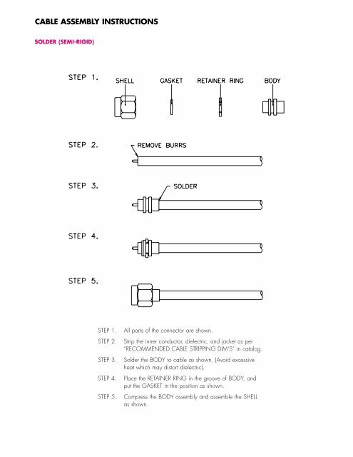
<strong>CABLE</strong> <strong>ASSEMBLY</strong> <strong>INSTRUCTIONS</strong>SOLDER (SEMI-RIGID)STEP 1.STEP 2.STEP 3.STEP 4.STEP 1.STEP 2.STEP 3.STEP 4.All parts of the connector are shown.Strip the inner conductor, dielectric, and jacket as per"RECOMMENDED <strong>CABLE</strong> STRIPPING DIM'S" in catalog.Solder inner conductor to the contact pin of MAIN BODY,and solder cable jacket to the MAIN BODY as shown.Press the COVER into the MAIN BODY until it is flat withthe MAIN BODY.
<strong>CABLE</strong> <strong>ASSEMBLY</strong> <strong>INSTRUCTIONS</strong>SOLDER (SEMI-RIGID)STEP 1.STEP 2.STEP 3.STEP 4.STEP 5.STEP 1.STEP 2.STEP 3.STEP 4.STEP 5.All parts of the connector are shown.Strip the inner conductor, dielectric, and jacket as per"RECOMMENDED <strong>CABLE</strong> STRIPPING DIM'S" in catalog.Slide the INSULATOR onto inner conductor against the jacket.Then insert inner conductor into the CONTACT PIN and solderit as shown.Slide the SOLDER NUT onto cable.Insert cable and parts into the MAIN BODY, then screw theSOLDER NUT until it is tight and solder it as shown.
<strong>CABLE</strong> <strong>ASSEMBLY</strong> <strong>INSTRUCTIONS</strong>CRIMPSTEP 1.STEP 2.STEP 3.STEP 4.STEP 5.STEP 6.All parts of the connector are shown.Strip the cable inner conductor, dielectric, braid, and jacket as per“RECOMMENDED <strong>CABLE</strong> STRIPPING DIM’S” in catalog.Slide the HEX NUT and FERRULE onto cable. Then insert the BARRELinto braid and dielectric, and slide the FERRULE over braid andcrimp it as shown.Slide the REAR INSULATOR against the BARREL. Then insert innerconductor into the CONTACT PIN and solder it as shown.Slide the FRONT INSULATOR against the REAR INSULATOR.Insert cable and parts into the MAIN BODY, then screw the HEXNUT until it is tight.
<strong>CABLE</strong> <strong>ASSEMBLY</strong> <strong>INSTRUCTIONS</strong>CRIMP – CRIMPSTEP 1.STEP 2.STEP 3.STEP 4.STEP 5.All parts of the connector are shown. A crimp tool is necessary tocomplete the connection.Strip the cable inner conductor, dielectric, braid, and jacket as per“RECOMMENDED <strong>CABLE</strong> STRIPPING DIM’S” in catalog.Insert inner conductor into the CONTACT PIN, crimp it with thecrimp tool as shown. Then slide the FERRULE onto cable.Insert the MAIN BODY into braid and dielectric.Slide the FERRULE over braid, crimp it with the crimp tool as shown.
<strong>CABLE</strong> <strong>ASSEMBLY</strong> <strong>INSTRUCTIONS</strong>CRIMP – SOLDERSTEP 1.STEP 2.STEP 3.STEP 4.STEP 5.All parts of the connector are shown. A crimp tool is necessary tocomplete the connection.Strip the cable inner conductor, dielectric, braid, and jacket as per“RECOMMENDED <strong>CABLE</strong> STRIPPING DIM’S” in catalog.Insert inner conductor into the CONTACT PIN and solder on thecable. Then slide the FERRULE onto cable.Insert the MAIN BODY into braid and dielectric.Slide the FERRULE over braid, crimp it with the crimp tool as shown.
<strong>CABLE</strong> <strong>ASSEMBLY</strong> <strong>INSTRUCTIONS</strong>CRIMP – CRIMPSTEP 1.STEP 2.STEP 3.STEP 4.STEP 5.All parts of the connector are shown. A crimp tool isnecessary to complete the connection.Strip the inner conductor, dielectric, and jacket as per“RECOMMENDED <strong>CABLE</strong> STRIPPING DIM’S” in catalog.Slide the FERRULE onto cable, then fold back braid wireand slide the INSULATOR onto dielectric as shown.Insert inner conductor into the CONTACT PIN, crimp itwith crimp tool as shown.Push cable and parts into the MAIN BODY until it stops.Then slide the FERRULE over braid wire and against theMAIN BODY, crimp it with the crimp tool as shown.
<strong>CABLE</strong> <strong>ASSEMBLY</strong> <strong>INSTRUCTIONS</strong>CRIMP – CRIMPSTEP 1.STEP 2.STEP 3.STEP 4.STEP 5.All parts of the connector are shown. A crimp tool is necessary tocomplete the connection.Strip the cable inner conductor, dielectric, braid, and jacket as per“RECOMMENDED <strong>CABLE</strong> STRIPPING DIM’S” in catalog.Slide the FERRULE onto cable, then fold back braid wire and slidethe SPACER and INSULATOR onto dielectric as shown.Insert inner conductor into the CONTACT PIN, crimp it with thecrimp tool as shown.Push cable and parts into the MAIN BODY until it stops. Then slidethe FERRULE over braid wire and against the MAIN BODY, crimp itwith the crimp tool as shown.
<strong>CABLE</strong> <strong>ASSEMBLY</strong> <strong>INSTRUCTIONS</strong>CLAMP – SOLDER<strong>CABLE</strong> <strong>ASSEMBLY</strong> <strong>INSTRUCTIONS</strong>STEP 1.STEP 2.STEP 3.STEP 4.STEP 5.All parts of the connector are shown.Strip the cable inner conductor, dielectric, and jacket as per“RECOMMENDED <strong>CABLE</strong> STRIPPING DIM’S” in catalog.Insert inner conductor into the CONTACT PIN and solder it asshown. Then slide the HEX NUT, WASHER, and GASKET ontocable one by one.Place the TOP HAT over braid and push back against cablejacket. Fold back braid wire as shown.Insert cable and parts into the MAIN BODY, then screw theHEX NUT until it is tightened.
<strong>CABLE</strong> <strong>ASSEMBLY</strong> <strong>INSTRUCTIONS</strong>CLAMP – SOLDERSTEP 1.STEP 2.STEP 3.STEP 4.STEP 5.All parts of the connector are shown.Strip the cable inner conductor, dielectric, and jacket as per“RECOMMENDED <strong>CABLE</strong> STRIPPING DIM’S” in catalog.Slide the HEX NUT, WASHER, and GASKET onto cable one by one.Place the BRAID CLAMP over braid and push back against cablejacket. Fold back braid wire as shown, and slide the RING andREAR INSULATOR against the BRAID CLAMP. Then insert innerconductor into the CONTACT PIN and solder it.Insert cable and parts into the MAIN BODY, then screw the HEXNUT until it is tightened.
<strong>CABLE</strong> <strong>ASSEMBLY</strong> <strong>INSTRUCTIONS</strong>TWIST-ONSTEP 1.STEP 2.STEP 3.STEP 4.STEP 5.The connector is shown.Strip the cable inner conductor, dielectric, braid, and jacket as per“RECOMMENDED <strong>CABLE</strong> STRIPPING DIM’S” in catalog.Twist braid in a clockwise direction so that at least 0,8mm of dielectricis bared, and braid is left flat.Insert inner conductor into the back end of connector gently, and feedit into the guide hole.Push and screw connector onto cable in a clockwise direction until it stops.
<strong>CABLE</strong> <strong>ASSEMBLY</strong> <strong>INSTRUCTIONS</strong>WEDGE COMPRESSIONSTEP 1.STEP 2.STEP 3.STEP 4.All parts of the connector are shown.Strip the cable inner conductor, dielectric, and jacket as per“RECOMMENDED <strong>CABLE</strong> STRIPPING DIM’S” in catalog.Slide the HEX NUT onto cable, then insert the CONTACT<strong>ASSEMBLY</strong> under braid and jacket.Insert cable and parts into the MAIN BODY, then screw theHEX NUT until it is tight.
<strong>CABLE</strong> <strong>ASSEMBLY</strong> <strong>INSTRUCTIONS</strong>CLAMPSTEP 1.STEP 2.STEP 3.STEP 4.STEP 5.STEP 1.STEP 2.All parts of the connector are shown.Strip the cable inner conductor, dielectric, outer conductor, and jacketas per "RECOMMENDED <strong>CABLE</strong> STRIPPING DIM'S" in catalog.STEP 3. Thread the GASKET onto the cable until it is against thecable jacket.STEP 4.STEP 5.Thread the CLAMP NUT onto the cable until the A dimension is1–1.5 mm, then push the TOP HAT onto the outer conductor of cableinside as shown.Thread the MAIN BODY onto the CLAMP NUT and tighten theconnection with wrenches, hold the CLAMP NUT and turn only theMAIN BODY.
<strong>CABLE</strong> <strong>ASSEMBLY</strong> <strong>INSTRUCTIONS</strong>CLAMPSTEP 1.STEP 2.STEP 3.STEP 4.STEP 5.STEP 6.All parts of the connector are shown.Strip the cable inner conductor, dielectric, and jacket as per“RECOMMENDED <strong>CABLE</strong> STRIPPING DIM’S” in catalog. Thenslide the NUT, WASHER, and GASKET onto cable.Place the BRAID CLAMP over braid and push back against cable jacket.Fold back braid wire as shown.Slide the TOP HAT against the BRAID CLAMP. Then insert inner conductorinto the CONTACT PINs and solder them.Insert the CONTACT PINs into the INSULATOR until the INSULATOR isagainst the TOP HAT.Insert cable and parts into the MAIN BODY, aligning slot of the INSULATORwith key in the MAIN BODY. Then screw the NUT until it is tight.
<strong>CABLE</strong> <strong>ASSEMBLY</strong> <strong>INSTRUCTIONS</strong>SOLDER (US STANDARD)STEP 1.STEP 2.STEP 3.STEP 4.All parts of the connector are shown.Strip the cable inner conductor, dielectric, braid, and jacket as per“RECOMMENDED <strong>CABLE</strong> STRIPPING DIM’S” in catalog.Slide the SHELL onto cable, then screw the MAIN BODY onto cableand solder it as shown.Slide the SHELL forward and screw in place on the MAIN BODY.
<strong>CABLE</strong> <strong>ASSEMBLY</strong> <strong>INSTRUCTIONS</strong>SOLDER (WITH REDUCER)STEP 1.STEP 2.STEP 3.STEP 4.STEP 5.All parts of the connector are shown.Strip the cable inner conductor, dielectric, braid, and jacket as per“RECOMMENDED <strong>CABLE</strong> STRIPPING DIM’S” in catalog.Slide the SHELL and REDUCER onto cable, then fold back braidwire over the REDUCER as shown.Screw the MAIN BODY onto the REDUCER and solder it as shown.Slide the SHELL forward and screw in place on the MAIN BODY.
<strong>CABLE</strong> <strong>ASSEMBLY</strong> <strong>INSTRUCTIONS</strong>FCPSTEP 1.STEP 2.STEP 3.STEP 4.All parts of the connector are shown.Strip the cable inner conductor, dielectric, braid, and jacket as per“RECOMMENDED <strong>CABLE</strong> STRIPPING DIM’S” in catalog.Slide the FERRULE and SHELL onto cable one by one, and insert theMAIN BODY into braid and dielectric until it is against cable jacket.Then crimp the CONTACT PIN as shown.Slide the SHELL onto the MAIN BODY, and push the FERRULE until itis against the MAIN BODY. If inner conductor sticks out beyond theCONTACT PIN, trim it.
<strong>CABLE</strong> <strong>ASSEMBLY</strong> <strong>INSTRUCTIONS</strong>CRIMP – CRIMPSTEP 1.STEP 2.STEP 3.STEP 4.STEP 5.All parts of the connector are shown. A crimp tool is necessary tocomplete the connection.Strip the cable inner conductor, dielectric, braid, and jacket as per“RECOMMENDED <strong>CABLE</strong> STRIPPING DIM’S” in catalog.Insert inner conductor into the CONTACT PIN, crimp it with thecrimp tool as shown. Then slide the FERRULE and SHELL onto cableone by one.Insert the MAIN BODY under braid and dielectric.Slide the SHELL until it is against the MAIN BODY, then slide theFERRULE over braid, crimp it with the crimp tool as shown.
<strong>CABLE</strong> <strong>ASSEMBLY</strong> <strong>INSTRUCTIONS</strong>CRIMPSTEP 1.STEP 2.STEP 3.STEP 4.STEP 1.STEP 2.STEP 3.STEP 4.All parts of the connector are shown. A crimp tool is necessary tocomplete the connection.Strip the inner conductor, dielectric, braid, and jacket as per"RECOMMENDED <strong>CABLE</strong> STRIPPING DIM'S" in catalog.Insert cable into the back end of MAIN BODY gently, and feed itinto the guide hole.Crimp it with the crimp tool as shown.