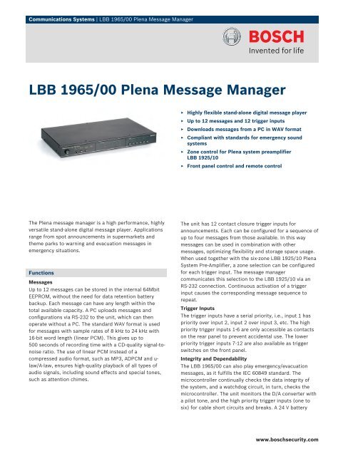
LBB 1965/00 Plena Message Manager - WES Components
LBB 1965/00 Plena Message Manager - WES Components
LBB 1965/00 Plena Message Manager - WES Components
Create successful ePaper yourself
Turn your PDF publications into a flip-book with our unique Google optimized e-Paper software.
2 | <strong>LBB</strong> <strong>1965</strong>/<strong>00</strong> <strong>Plena</strong> <strong>Message</strong> <strong>Manager</strong>backup connection with automatic fail-safe providescontinued operation if the mains power should fail. A20 kHz pilot tone can be mixed with the output signal tosupervise the link to the next amplifier. This also works forloudspeaker supervision in combination with 20 kHzdetectors. Any failure causes a red LED fault indication,and activates a fault output contact.Loop-through FacilityThe <strong>LBB</strong> <strong>1965</strong>/<strong>00</strong> provides a loop-through facility withbalanced XLR and unbalanced cinch inputs and outputs.This allows the unit to be inserted into an existing audiolink. As long as no announcements are playing, the signalinput is routed to the output. If an announcement begins,the input signal is interrupted and the announcement isrouted to the output.Updating<strong>Message</strong>s and configuration settings are uploaded from aPC. After uploading, the trigger inputs 7-12 can beconfigured by using the front panel switches, without theneed for a new upload or even a PC. <strong>Message</strong> content canbe monitored using the available headphone jack.Certifications and ApprovalsRegionCertificationEurope CE Declaration of ConformitySafety according to EN 6<strong>00</strong>65Immunity according to EN 55103-2Emission according to EN 55103-1Installation/Configuration Notes<strong>LBB</strong> <strong>1965</strong>/<strong>00</strong> back viewParts IncludedQuantityComponent1 <strong>LBB</strong> <strong>1965</strong> <strong>Plena</strong> <strong>Message</strong> <strong>Manager</strong>1 Power cord1 Set of 19" mounting brackets1 <strong>Plena</strong> CD1 Installation and User InstructionsTechnical SpecificationsElectricalMains power supplyVoltageInrush currentMax power consumptionBattery power supply230/115 VAC, ±10%, 50/60 Hz1.5 A at 230 VAC / 3 A at 115 VAC50 VAVoltage 24 VDC, +15% / -15%Current maxPerformanceSupported sample rates (fs)Frequency response@ fs=24kHz@ fs=22.05kHz1 A24 / 22.05 / 16 / 12 / 11.025 / 8 kHz1<strong>00</strong> Hz to 11 kHz (+1 / -3 dB)1<strong>00</strong> Hz to 10 kHz (+1 / -3 dB )@ fs=16kHz 1<strong>00</strong> Hz to 7.3 kHz (+1 / -3 dB )@ fs=12kHz@ fs=11.025kHz@ fs=8kHzDistortionS/N (flat at max volume)Supervision DACLine inputConnectorSensitivityImpedanceCMRRLine inputConnectorSensitivityImpedanceTrigger inputConnectorActivationSupervision methodLine outputConnectorNominal level1<strong>00</strong> Hz to 5.5 kHz (+1 / -3 dB)1<strong>00</strong> Hz to 5 kHz (+1 / -3 dB)1<strong>00</strong> Hz to 3.6 kHz (+1 / -3 dB)80 dB1 Hz pilot tone1 x3-pin XLR, balanced1 V20 kohm>25 dB (50 Hz-to 20 kHz)1 xCinch, unbalanced1 V20 kohm6 xScrewContact closureCable loop resistance check1 x3-pin XLR, balanced1 V, adjustable
<strong>LBB</strong> <strong>1965</strong>/<strong>00</strong> <strong>Plena</strong> <strong>Message</strong> <strong>Manager</strong> | 3Mains power supplyImpedanceLine outputConnectorNominal levelImpedance<strong>Message</strong> active outputConnectorRelayFault outputConnectorRelayInterconnectionConnectorPC protocol<strong>LBB</strong> 1925/10 protocol<strong>Message</strong>sData formatMemory capacityRecording/playback timeNumber of messagesData retention timeMechanicalDimensions (H x W x D)WeightMountingColorEnvironmental
<strong>Plena</strong> <strong>Message</strong> <strong>Manager</strong>enInstallation and Operating Manual<strong>LBB</strong> <strong>1965</strong>
<strong>Plena</strong> <strong>Message</strong> <strong>Manager</strong> | Installation and Operating Manual | Important safeguards en | 3Important safeguards1 Read instructions - All the safety instructions for useshould be read before the system is operated.2 Retain instructions - The safety instructions andinstructions for use should be retained for futurereference.3 Heed warnings - All warnings on the unit and in theoperating instructions should be adhered to.4 Follow instructions - All operating instructions andinstructions for use should be followed.5 Cleaning - Unplug system units from the mains outletbefore cleaning. Do not use liquid cleaners or aerosolcleaners. Use a damp cloth for cleaning.6 Attachments - Do not use attachments notrecommended by the product manufacturer as they maycause hazards.7 Water and Moisture - Do not use this unit near water, forexample near a bathtub, washbowl, kitchen sink, orlaundry basket, in a wet basement, near a swimmingpool, in an unprotected outdoor installation or any areawhich is classified as a wet location.8 Accessories - Do not place this unit on an unstable stand,tripod, bracket or mount. This unit may fall, causingserious injury to a person and serious damage to theunit. Use only a stand, tripod, bracket or mountrecommended by the manufacturer, or sold with theproduct. Any mounting of the unit should follow themanufacturer's instructions, and should use a mountingaccessory recommended by the manufacturer. Anappliance and cart combination should be moved withcare. Quick stops, excessive force, and uneven surfacesmay cause the appliance and cart combination tooverturn.9 Ventilation - Openings in the enclosure, if any, areprovided for ventilation and to ensure reliable operationof the unit and to protect it from overheating. Theseopenings must not be blocked or covered. The unitshould not be placed in a built-in installation unlessproper ventilation is provided or the manufacturer'sinstructions have been adhered to.10 Power sources - Units should be operated only from thetype of power source indicated on the marking label. Ifyou are not sure of the type of power supply you plan touse, consult your appliance dealer or local powercompany. For units intended to operate from batterypower, or other sources, refer to the "Installation andUser Instructions".11 Grounding or polarisation - This unit may be equippedwith a polarised alternating current line plug (a plughaving one blade wider than the other). This plug will fitinto the power outlet only one way. This is a safetyfeature. If you are unable to insert the plug fully into theoutlet, try reversing the plug. If the plug still fails to fit,contact your electrician to replace your obsolete outlet.Do not defeat the safety purpose of the polarised plug.Alternatively, this unit may be equipped with a 3-wiregrounding type plug having a third (grounding) pin.This plug will only fit into a grounding-type poweroutlet. This is a safety feature. If you are unable to insertthe plug into the outlet, contact your electrician toreplace your obsolete outlet. Do not defeat the safetypurpose of the grounding-type lug.12 Power-Cord Protection - Power supply cords should berouted so that they are not likely to be walked on orpinched by items placed upon or against them, payingparticular attention to cords and plugs, conveniencereceptacles, and the point where they exit from theappliance.13 Overloading - Do not overload outlets and extensioncords as this can result in a risk of fire or electrical shock.14 Object and Liquid Entry - Never push objects of anykind into this unit through openings as they may touchdangerous voltage points or short-out parts that couldresult in a fire or electric shock. Never spill liquid of anykind on the unit.15 Servicing - Do not attempt to service this unit yourself asopening or removing covers may expose to dangerousvoltage or other hazards. Refer all servicing to qualifiedservice personnel.16 Damage Requiring Service - Unplug the unit from theoutlet and refer servicing to qualified service personnelunder the following conditions:• When the power-supply cord or plug is damaged.• If liquid has been spilled, or objects have fallen intothe unit.• If the unit has been exposed to rain or water.• If the unit does not operate normally by followingthe instructions for use. Adjust only those controlsthat are covered by the instructions for use, as animproper adjustment of other controls may result indamage and will often require extensive work by aqualified technician to restore the units to theirnormal operation.• If the unit has been dropped or the unit has beendamaged.• When the unit exhibits a distinct change inperformance; this indicates a need for service.17 Replacement Parts - When replacement parts arerequired be sure the service technician has usedreplacement parts specified by the manufacturer or partswhich have the same characteristics as the original part.Unauthorised substitutions may result in fire, electricshock or other hazards.18 Safety Check - Upon completion of any service orrepairs to the units, ask the service technician to performsafety checks to determine that the unit is in properoperating condition.19 Lightning - For added protection of the units during alightning storm, or when it is left unattended and unusedfor long periods of time, unplug it from the wall outletand disconnect the cable system. This will preventdamage to the unit due to lightning and power-linesurges.Bosch Security Systems | 2<strong>00</strong>3-09 | 9922 141 50502en
<strong>Plena</strong> <strong>Message</strong> <strong>Manager</strong> | Installation and Operating Manual | About this manual en | 4About this manualThis manual provides all the information required to install and operate the unit.ConventionsWarningFollow these instructions to prevent personal injury.CautionFollow these instructions to prevent damage to the equipment.NoteRead these instructions for tips and other useful information.Safety precautionsWarningDo not open the unit when it is connected to the mains. The unit contains non-insulated parts, which cancause electric shock.CautionThere are no user-serviceable parts inside the unit. Service must be done by qualified personnel.Bosch Security Systems | 2<strong>00</strong>3-09 | 9922 141 50502en
<strong>Plena</strong> <strong>Message</strong> <strong>Manager</strong> | Installation and Operating Manual | Table of contents en | 5Table of contentsImportant safeguards..........................................................................................................................................................3About this manual ..............................................................................................................................................................4Safety precautions...............................................................................................................................................................4Table of contents ................................................................................................................................................................51 About the equipment ........................................................................................................................................................71.1 Features ......................................................................................................................................................................81.2 Capacity .....................................................................................................................................................................81.3 Package ......................................................................................................................................................................91.4 Controls and indicators (front) ................................................................................................................................91.5 Controls and connections (rear) ............................................................................................................................102 Installation in rack ...........................................................................................................................................................113 External settings and connections .................................................................................................................................123.1 Connecting the DC supply (battery) .....................................................................................................................123.2 Normal audio connections .....................................................................................................................................133.3 Loopthrough audio connections ...........................................................................................................................143.4 Trigger input connections ......................................................................................................................................153.5 Mains connection ....................................................................................................................................................164 Operation .........................................................................................................................................................................174.1 Uploading ................................................................................................................................................................174.2 Play-back messages .................................................................................................................................................194.3 Monitoring ...............................................................................................................................................................204.4 Supervision ..............................................................................................................................................................204.5 Manual editing of messages ...................................................................................................................................205 Technical data ..................................................................................................................................................................225.1 Electrical ..................................................................................................................................................................225.2 <strong>Message</strong>s ..................................................................................................................................................................225.3 Inputs ........................................................................................................................................................................225.4 Outputs .....................................................................................................................................................................225.5 Controls ....................................................................................................................................................................235.6 Environmental conditions ......................................................................................................................................235.7 General .....................................................................................................................................................................23Bosch Security Systems | 2<strong>00</strong>3-09 | 9922 141 50502en
<strong>Plena</strong> <strong>Message</strong> <strong>Manager</strong> | Installation and Operating Manual | About the equipmenten | 71 About the equipmentBattery 24VMAINSF1F2Power230V115VStabiliser15 VoltStabiliser18VStabiliser12VStabiliser5VRS232 to PCRS232 to <strong>LBB</strong> 1925Trigger Inputs1FaultLEDFault Relay23456789101112ProgramMonitor8x DIPSwitchTr. 7Tr. 8Tr. 9Tr. 10Tr. 11Tr. 12I/OExpanderEeprom(Flash)Memory32 MbitEeprom(Flash)Memory32 MbitMCUMCUWave PlayerWatchdogWatchdogI/OExpanderMSG Active Relay13579111357911ProgramLED246<strong>Message</strong>8 LED's101224CNONCCNONC6Trigger8 LED's1012DAC L R1HzPilot toneDetectorDAC SupervisionLow-pass20kHzPilot toneGeneratorLoop-throughInputBalanced1 23UnbalancedHigh-passOutput1 23BalancedFigure 1.1UnbalancedBosch Security Systems | 2<strong>00</strong>3-09 | 9922 141 50502en
<strong>Plena</strong> <strong>Message</strong> <strong>Manager</strong> | Installation and Operating Manual | About the equipmenten | 8The <strong>Plena</strong> <strong>Message</strong> <strong>Manager</strong> functions as an audio source in the overall <strong>Plena</strong> PA-system. With this unit it ispossible to play, via other <strong>Plena</strong> units, pre-recorded messages that are triggered from external sources or the unit'sfront panel switches.These pre-recorded messages (that can be made on a PC in .wav-format) can be used for various purposes, e.g.routine messages or emergency calls. The messages are stored in solid state memories (Eeproms) and arecontinuously supervised on availability.When the message manager is connected to the <strong>Plena</strong> System Pre-amplifier (<strong>LBB</strong>1925), it is also possible todistribute the messages in pre-programmed zones.The unit is delivered with the mains voltage selector set to 230 Vac. This selector can be set to 115 Vac.The unit is not provided with a separate power ON indication. One message LED on the front panel will always belit (thus functioning as a power ON indication) as at least one message will be loaded. In case no messages areloaded, this fault situation is indicated by the fault LED.1.1 Features- Up to 12 different messages can be stored.- Up to 12 message sequences or announcements (each consisting of up to 4 different messages + zone information)can be stored.- <strong>Message</strong>s can be edited, assembled and uploaded by means of a PC.- The message content is continuously supervised on availability.- The cabling of trigger inputs 1 through 6 can be supervised on cuts and short-circuits.- Mains supply voltage (230/115 Vac) can be supervised.- Pilot tone can be added to supervise the audio connection to an amplifier or the sound system.- Internal pilot tone to supervise the internal audio path.- Support for various sample frequencies to balance audio quality versus message length1.2 CapacityThe storage device of the messages is a built-in block-erasable EEPROM with fixed storage capacity of 8.38 MByte.The message manager accepts .wav-files with sample frequencies of 24, 22.050, 16, 12, 11.025 and 8 kHz. The wordlength is fixed to 16 bits. This means that the distortion and signal to noise level is of CD quality. Lower samplefrequencies mean a decrease in audio quality (lower bandwidth), but an increase in message length. See the tablebelow.Sample frequency 24 kHz 22.050 kHz 16 kHz 12 kHz 11.025 kHz 8 kHzAudio bandwidth (approx.) 11 kHz 10 kHz 7.3 kHz 5.5 kHz 5 kHz 3.6 kHzMax. length of all 12 messages 170 s 180 s 250 s 335 s 360 s 5<strong>00</strong> sBosch Security Systems | 2<strong>00</strong>3-09 | 9922 141 50502en
<strong>Plena</strong> <strong>Message</strong> <strong>Manager</strong> | Installation and Operating Manual | About the equipmenten | 91.3 PackageThe message manager is packed with the following parts:- 2x RS232 cable for connection with a PC and a system pre-amplifier (9-pin male/female)- 1x mains cable- 1x cable with Cinch connectors- 1x cable with XLR connectors (3-pin male + female)- 1x Installation and User Instructions- 2x 19" brackets to install the unit in a 19" rack- 1x CD-ROM with software to upload messages1.4 Controls and indicators (front)<strong>Plena</strong> <strong>Message</strong> <strong>Manager</strong>Figure 1.21 2 3 4 5 6 78 91 Power ON/OFF button2 Headphone output socket (6.3 mm phone jack)3 Monitor pushbutton (= headphone selection)4 Program mode pushbutton5 Program mode indicator LED6 Fault indicator LED7 <strong>Message</strong> indicator LEDs8 Trigger indicator LEDs9 Pushbuttons for:- starting announcements 7-12- manual (re)programming of trigger inputs 7-12Bosch Security Systems | 2<strong>00</strong>3-09 | 9922 141 50502en
<strong>Plena</strong> <strong>Message</strong> <strong>Manager</strong> | Installation and Operating Manual | About the equipmenten | 101.5 Controls and connections (rear)3913 15<strong>LBB</strong> <strong>1965</strong>/<strong>00</strong>89<strong>00</strong> 196 5<strong>00</strong>5InLoop throughSupervisionPilottoneMainsCNC NO+24VMsg Active TriggerInputNC C NO 1 2 3 4 5 6 7 8 9 10 11 12Fault GNDRS232 to <strong>LBB</strong>1925Apparatus delivered connected for 230V~115V~ 230V~ 50/60HzPilot <strong>Message</strong>ToneOutInOutTrigger Input 1-6OFFON12345678RS232 to PCWKS/NWarningThis apparatus must be earthedRated InputPower:50VATo.5L250V1 2 4 5 6 7 8 101112 14 16Figure 1.31 Pilot tone volume control2 <strong>Message</strong> volume control3 Loopthrough input (Cinch)4 Line- and loopthrough output (Cinch)5 Loopthrough input (XLR female)6 Line- and loopthrough output (XLR male)7 DIP-switches (8 pcs) for supervision of trigger inputs1 through 6, mains and pilot tone8 24 Vdc input (terminal)9 <strong>Message</strong> active control output (terminal)10 Fault control output (terminal)11 Trigger inputs (terminal)12 RS232 female socket for connection to a PC13 RS232 male socket for connection to a systempreamplifier (<strong>LBB</strong>1925/10)14 Earth connection screw15 Mains voltage selector (115/230 Vac)16 Mains socket (3 pole)Bosch Security Systems | 2<strong>00</strong>3-09 | 9922 141 50502en
<strong>Plena</strong> <strong>Message</strong> <strong>Manager</strong> | Installation and Operating Manual | Installation in racken | 112 Installation in rack<strong>Plena</strong> <strong>Message</strong> <strong>Manager</strong>Figure 2.1The message manager is delivered for tabletop use, but you can mount it in a 19" rack using the brackets suppliedwith the unit. In case of rack mounting, you must:• remove the 4 feet from the bottom of the unit. Without the feet, the unit is 1U high.• ensure that the ambient temperature of the unit in the rack does not exceed 55 °C.Bosch Security Systems | 2<strong>00</strong>3-09 | 9922 141 50502en
SupervisionPilo t tone<strong>LBB</strong> <strong>1965</strong>/ 089 0 196 5 05PilotTone <strong>Message</strong>OutSupervisionMainsPilo toneO FON1 2 3 4 5 6 7 8CNC NONC CNO15V~ 230V~Warning50/60HzT0.5L250V<strong>Plena</strong> <strong>Message</strong> <strong>Manager</strong> | Installation and Operating Manual | External settings and connectionsen | 123 External settings and connections3.1 Connecting the DC supply (battery)InLoop throughInTri ge r Inpu t 1-6+ Ms g Active24V -Out1 2 3 4 5 6 7 8Tri ge r InputFault GND1 2 3 4 5 6 7 8 9 10 1 12OutRS232 toA paratu s delivere d co necte d for 230V~InMainsTrigge r Inpu t1-6CNC NO+ Ms g Active24V NC C-RS232 to PCWK.S/N.This a paratus must be earthedOut1 2 345 6 78OFFTrigge r InputNOFault GND1 2 3 4ate d InputPower:50VA1234567 8ON14- +F12 VDC 12 VDC- +F=1.5AFigure 3.1The message manager has a 24 Vdc input (screw terminal), which you can use to connect a back up power supply,e.g. batteries. You can earth (14) the unit to increase the electrical stability of the system.CautionThe connection cable must have an in-line fuse. Use the type of fuse as mentioned in the illustration.Bosch Security Systems | 2<strong>00</strong>3-09 | 9922 141 50502en
3 15 427 63 8 15 42Input 1 PriorityLoopthrough 1Input 2 ProgramLoopthrough 2Input 1 Priority +2..24V-Input 1 -0V-Input 2Input 2 Enable +2..24V-Enable -0V-MuteSlave Input 1<strong>00</strong>V 1<strong>00</strong>V0Input 1 PriorityLoopthrough 1Input 2 ProgramLoopthrough 2Input 1 Priority +2..24V-Input 1 -0V-Input 2Input 2 Enable +2..24V-Enable -0V-MuteSlave Input 1<strong>00</strong>V 1<strong>00</strong>V023GND131<strong>00</strong>V070V08ohm1<strong>00</strong>V/70VPriorityPriority Only0No Priority01<strong>00</strong>V070V08ohm1<strong>00</strong>V/70VPriorityPriority Only0No Priority0This apparatus must be earthedThis apparatus must be earthed<strong>Plena</strong> <strong>Message</strong> <strong>Manager</strong> | Installation and Operating Manual | External settings and connectionsen | 133.2 Normal audio connections<strong>LBB</strong><strong>1965</strong><strong>LBB</strong> <strong>1965</strong>/<strong>00</strong>89<strong>00</strong> 196 5<strong>00</strong>5Loop throughIn+ Msg Active TriggerInputSupervision C 24V NC C NO 1 2 3 4 5 6 7 8 9 10 11 12NC NOFault GNDPilottoneMainsRS232 to <strong>LBB</strong>1925Apparatus delivered connected for 230V~115V~ 230V~ 50/60HzPilot <strong>Message</strong>ToneOutInOutTrigger Input 1-6OFFON12345678RS232 to PCWKS/NWarningRated InputPower:50VATo.5L250V2 4 6<strong>LBB</strong>1961Warning<strong>LBB</strong>1925Tel/EMGTrigger 1 Trigger 2<strong>LBB</strong>1925/1089<strong>00</strong>19251<strong>00</strong>5115/230V~,50/60HzNo.Apparatus delivered 115V 230Vconnected for 230V-0/Line1. Audio+2.0V3.Audio-4.24Vd.c.5. Allcall6.Data-PCAudoln7.Data+8.Chs.GNDRS232 CD Aux1<strong>00</strong>V 01<strong>00</strong>V 01<strong>00</strong>V 0 1<strong>00</strong>V 01- 34 5/LineLRMasterOutOut+- 1GND+- 21<strong>00</strong>V 0 1<strong>00</strong>V 0 1<strong>00</strong>V 0 1<strong>00</strong>V 0+24V-+24V-WarningThis apparatus must be earthedRated InputPower : 50VAT0.5L 250V<strong>LBB</strong>1938Input 1 Input 2 Slave InputPriority Enable 1<strong>00</strong>VDirect O utput2..24V GND 2..24V GND 1<strong>00</strong>V 0Default Off Default OnInput 1-PriorityInput 2-Program1<strong>00</strong>V 0 70V 0 8Priority Controlled OutputPriority Only No PriorityInputLoopthroughInputLoopthrough1<strong>00</strong>V 0 1<strong>00</strong>V 0WarningThis apparatus must be earthed<strong>LBB</strong>1938Input 1 Input 2 Slave InputPriority Enable 1<strong>00</strong>VDirect O utput2..24V GND 2..24V GND 1<strong>00</strong>V 0Default Off Default OnInput 1-PriorityInput 2-Program1<strong>00</strong>V 0 70V 0 8Priority Controlled OutputPriority Only No PriorityInputLoopthroughInputLoopthrough1<strong>00</strong>V 0 1<strong>00</strong>V 0WarningThis apparatus must be earthedFigure 3.2Bosch Security Systems | 2<strong>00</strong>3-09 | 9922 141 50502en
3 15 42GND23Input 1 PriorityLoopthrough 1Input 2 ProgramLoopthrough 2Input 1 Priority2..24V-Input 10V-Input 2Input 2 Enable2..24V-Enable0V-MuteSlave Input 1<strong>00</strong>V 1<strong>00</strong>V0GND13This apparatus must be earthedThis apparatus must be earthed<strong>Plena</strong> <strong>Message</strong> <strong>Manager</strong> | Installation and Operating Manual | External settings and connectionsen | 14The message manager can be used with all <strong>Plena</strong> amplifiers via the Cinch output (4) or the XLR Output (6). Thelevel of the messages can be set via the message volume control (2).To fully benefit from the features of the message manager in the overall <strong>Plena</strong> system (e.g. to distribute pre-recordedmessages to pre-programmed zones) the unit must be connected via the system pre-amplifier <strong>LBB</strong>1925. To do this,use the RS232 cable and the audio cable supplied.There are several ways to connect the message manager to the system pre-amplifier:- Connecting the Cinch output (4) of the message manager to the Cinch PC Audio In (R) line input of the systempre-amplifier, as shown in figure 3.2 (in which the <strong>LBB</strong>1961 functions as a BGM source).- Connecting the XLR output (6) of the message manager to the points 1 and 3 of the 8-pole DIN socket of thesystem pre-amplifier.3.3 Loopthrough audio connections<strong>LBB</strong>1920Dir.Out1 Dir.Out2 Dir.Out3 Dir.Out4 Ins/ Casc / Emgln Ins/ Casc Out Master Line Out Master Mic. Out115V230VIns/Casc<strong>LBB</strong> 1920/<strong>00</strong>89<strong>00</strong> 192 <strong>00</strong><strong>00</strong>5115/230V~,50/60HzNo.Apparatus deliviredconnected for 230V-1- 34 51- 34 5+- 1+- 21- 34 51- 34 51- 34 5WarningRated inputpower: 25VAT0,5AL250VLEMG OutDC InDC OutR1/Line 2/Line 3/Line4/Line+24V-+24V-<strong>LBB</strong><strong>1965</strong><strong>LBB</strong> <strong>1965</strong>/<strong>00</strong>89<strong>00</strong> 196 5<strong>00</strong>5Loop throughIn+ Msg Active TriggerInputSupervision C 24V NC C NO 1 2 3 4 5 6 7 8 9 10 11 12NC NOFault GNDPilottoneMainsRS232 to <strong>LBB</strong>1925Apparatus delivered connected for 230V~230V~ 50/60HzPilot <strong>Message</strong>ToneOutInOutTrigger Input 1-6OFFON12345678RS232 to PCWKS/NWarningRated InputPower:50VATo.5L250V<strong>LBB</strong>1938Input 1 Input 2 Slave InputPriority Enable 1<strong>00</strong>V+-+-1<strong>00</strong>V070V08ohmDirect O utput2..24V GND 2..24V GND 1<strong>00</strong>V 0Default Off Default OnInput 1-PriorityInput 2-Program1<strong>00</strong>V/70VPriority Only0No Priority01<strong>00</strong>V 0 70V 0 8Priority Controlled OutputPriority Only No PriorityPriorityInputLoopthroughInputLoopthrough1<strong>00</strong>V 0 1<strong>00</strong>V 0WarningThis apparatus must be earthedFigure 3.3It is possible to connect the <strong>LBB</strong><strong>1965</strong> message manager between a mixer pre-amplifier and a power amplifier.When the message manager is not active, the mixer pre-amplifier is routed to the power amplifier. However, whenthe message manager becomes active, this loopthrough connection is interrupted and the message manager isswitched to the power amplifier.Figure 3.3 shows this configuration example in which the <strong>Plena</strong> Mixer Pre-amplifier <strong>LBB</strong>1920 is used with a <strong>Plena</strong>Power Amplifier <strong>LBB</strong>1938. This is a high priority application, as the message manager has absolute priority.Bosch Security Systems | 2<strong>00</strong>3-09 | 9922 141 50502en
<strong>Plena</strong> <strong>Message</strong> <strong>Manager</strong> | Installation and Operating Manual | External settings and connectionsen | 153.4 Trigger input connections<strong>LBB</strong> <strong>1965</strong>/<strong>00</strong>89<strong>00</strong> 196 5<strong>00</strong>5InLoop throughSupervisionPilottoneMainsCNC NO+24VMsg Active TriggerInputNC C NO 1 2 3 4 5 6 7 8 9 10 11 12Fault GNDRS232 to <strong>LBB</strong>1925Apparatus delivered connected for 230V~115V~ 230V~ 50/60HzPilot <strong>Message</strong>ToneOutInOutTrigger Input 1-6OFFON12345678RS232 to PCWKS/NWarningThis apparatus must be earthedRated InputPower:50VATo.5L250V1 101110kΩ3.3kΩFigure 3.417<strong>Message</strong> sequences or announcements are started with make contacts (17). These make contacts are connected tothe trigger input screw terminals (11). The cabling of the first six trigger input contacts (1 through 6) can havesupervision by means of a window comparator. Normal operation of these inputs requires two series connectedresistors of 10 kOhm and 3.3 kOhm, permanently connected to the far end of the cable connected to each triggerinput. Triggering occurs by short-circuiting the 10 kOhm resistor as shown in figure 3.4.Open or short-circuited cables to such an input result in a fault situation that is detected by the window comparator.The fault indicator LED at the front will light up and the internal fault relay will be unpowered which gives acontact change on the screw terminals (10) at the rear.Via the dipswitches 1 through 6 at the rear of the unit supervision of each individual trigger input (1 - 6) can beenabled ('ON') or disabled ('OFF'). When disabled these inputs act the same as inputs 7 through 12.Via dipswitch # 7 it is possible to enable mains failure checking. When enabled ('ON') the fault indicator LED at thefront will light up and the internal fault relay will go to the unpowered state upon mains failure, although the unitmay continue to work on the 24 Vdc battery.When disabled ('OFF') switching between mains and battery operation is automatic and will not be noticed.Via dipswitch # 8 it is possible to switch ON a 20 kHz pilot tone to the output signal for supervision of the cable byconnecting equipment. The level of the pilot tone is adjustable (from 'OFF' to -14dB with respect to maximum audiolevel) via the pilot tone volume control (1). The default volume level is -20 dB.Bosch Security Systems | 2<strong>00</strong>3-09 | 9922 141 50502en
<strong>LBB</strong> <strong>1965</strong>/<strong>00</strong>89 0196 5 <strong>00</strong>5PilotTone <strong>Message</strong>OutSupervisionMainsPilo toneCNC NOO FON1 2 3 4 5 6 7 8NC CNORS232 to.RS232 to PCWK.S/N.15V~ 230V~Warning50/60Hzate d InputPower:50VAT0.5L250V<strong>Plena</strong> <strong>Message</strong> <strong>Manager</strong> | Installation and Operating Manual | External settings and connectionsen | 163.5 Mains connectionInLoop throughInTri ge r Inpu t 1-6+ Ms g Active24V -Out1 2 3 4 5 6 7 8Tri ge r InputFault GND1 2 3 4 5 6 7 8 9 10 1 12A paratu s delivere d co necte dfor 230V~This a paratus must be earthed~15Figure 3.5Use the supplied mains cord to connect the system to the mains supply.NoteIf necessary set the mains voltage switch (15) to the required voltage using a sharp object, e.g. a smallscrewdriver.Bosch Security Systems | 2<strong>00</strong>3-09 | 9922 141 50502en
<strong>Plena</strong> <strong>Message</strong> <strong>Manager</strong> | Installation and Operating Manual | Operationen | 174 Operation4.1 Uploading<strong>Plena</strong> <strong>Message</strong> <strong>Manager</strong>Figure 4.11 2 3 4 5 6 78 9To upload the messages and to configure the sequence of the messages, a PC must be used that meets the followingminimum requirements:- Pentium processor with a clock frequency of 1<strong>00</strong> MHz or higher- Operating system: Windows 95® or higher- CD-ROM driveTo prepare and to record the messages the standard available Windows® operating system can be used, but it isalso possible to purchase the messages from a studio. All messages must be stored as .wav files in the PC. Onlymono .wav files with sample frequencies of 24, 22.050, 16, 12, 11.025 and 8 kHz and a word length of 16 bits can beused. The sample frequency for each separate message can be different. See §1.2.To create messages or message sequences use the software on the CD-ROM supplied with the unit. To install thissoftware proceed as follows:• Close all applications that are open.• Insert the CD-ROM into the CD-ROM drive.• In case the Setup-program does not start up automatically, go to the next step. Otherwise follow the instructionson the screen.• Choose Run from the Start-menu.• Type 'd:\setup' (where 'd' is the CD-ROM drive).• Click OK or press Enter.• Follow the instructions on the screen.Upon installation proceed as follows:• Start the program. A screen similar to the following screen will appear.Figure 4.2Bosch Security Systems | 2<strong>00</strong>3-09 | 9922 141 50502en
<strong>Plena</strong> <strong>Message</strong> <strong>Manager</strong> | Installation and Operating Manual | Operationen | 18• In the left hand part of the screen the messages (max. 12) can be filled out. Proceed as follows:• Put the cursor in the File box of message # 1.• Type the message file name and location (or use the Browse box to go to the folder where the message isstored).• Proceed in the same way for all necessary messages. The Time, Size and Sample (sample rate) fields will automaticallybe filled out. During this process the program software will monitor the required memory capacityand the overall capacity that is available.• In the right hand part of the screen the sequence of the messages can be determined per trigger input. Proceed asfollows:• Click on the first [▼]-box to invoke a pull-down menu that contains all message numbers that have been filledout before.• Select one of the messages.• Select the next message, using the box to the right hand side of the first [▼]-box,. In this way up to four messagescan be selected, thus creating a programmed message sequence. The total time (in s) for this messagesequence will be displayed in the Time field.• If required click on the appropriate Zone number boxes in order to activate the corresponding zone(s). Thisoption is only of interest when the message manager is connected to a system pre-amplifier <strong>LBB</strong>1925.• Proceed in the same way for the other message sequences.• By clicking on the Play boxes in both the (left hand) <strong>Message</strong> screen and the (right hand) Trigger screen, the programmedmessages or message sequences will be audible over the PC's loudspeakers. Click again to stop thisaction.The menu bar at the top of the screen provides access to the File menu, the Setup menu and the Help menu.Upon selection of File a pull-down menu appears with the following options:- Open: Opens the dialog box to select a configuration file- Save: Saves the configuration file; it is recommended to create a separate folder for this purpose- Save as: Opens the dialog box to save the current configuration file- Save as text file: Opens Notepad for saving the configuration file as a .txt file or for printing; it is recommendedto select font type Arial for optimum alignment- Exit: Closes the programUpon selection of Setup a pull-down menu appears with the options to:- Select the RS232 Com port on the PC- Select the language on the screenUpon selection of Help you can select About <strong>Plena</strong> message manager to display the program release number.• Connect the supplied RS232 cable between the PC and the message manager. Use the RS232 female socket atthe rear of the unit.• Use the Com port selection button (in the pull-down menu under the Setup box) to select Com port 1 or 2 of thePC.• Click the Send messages and configuration button to transfer the file to the message manager. During this file transfer-which, depending on the file size of the messages, may take up to 45 minutes (at 115 kbps)- the percentage readybar on the screen indicates the progress of the uploading process. During uploading the program mode indicatorLED (5) on the front is lit.The message indicator LEDs (7) on the front of the unit will be continuously lit foreach message that is present and available in the message manager.Bosch Security Systems | 2<strong>00</strong>3-09 | 9922 141 50502en
<strong>Plena</strong> <strong>Message</strong> <strong>Manager</strong> | Installation and Operating Manual | Operationen | 19The status bar at the bottom of the screen contains three fields:- The STATUS field shows the progress of the uploading process.- The RS232 PORT shows the RS232 data during uploading.- The rightmost box of the status bar shows the actual upload time.On the supplied CD-ROM you can find a copy of the program R8brain (r8brain.exe, available as freeware atwww.voxenga.com).With the help of this program the sample rate of the .wav files can be changed, if required. It is recommended to usethe lowest sample rate that does not degrade the audio quality.Proceed as follows:• Start the program r8brain.exe.• Browse to the .wav file that must be modified.• Browse to the folder in which the modified file must be placed.• If required, change the message file name in the Browse menu.• Enter the output sample rate in the appropriate field or click on the output sample rate in the pull-down menu(sample rates like 12 kHz are not in the list, but can be entered from the keyboard).• Select 16-bit for Output bit depth and High or Very High for Conversion quality.• Click on Perform r8brain. A progress bar shows the progress of the conversion.• To convert from stereo .wav files to mono use the program Sound Recorder that comes with Windows®.Generally, you can find this program via Start > Programs > Accessories > Entertainment > Sound Recorder.4.2 Play-back messagesWhen an announcement is started via a trigger contact, the corresponding trigger indicator LED (8) will light up.Single-shot triggering and repeating mode is provided. After pressing a trigger switch the announcement is playedcompletely. If the trigger switch is still ON upon completion of the announcement, this announcement will berepeated until the trigger switch is released. Then it will complete the running announcement and stop.Within an announcement there is no possibility for repetition loops of individual messages. However the samemessage may be programmed in the sequence more than once (max. 4).Trigger inputs have serial priority, i.e. input 1 has priority over trigger input 2, 2 over 3, etc.When an announcement is overridden with an announcement with a higher priority, the first indicator LED willextinguish and the new LED will light up. Lower priority triggers will be ignored.The LED of the running message is flashing (2 Hz). If the current announcement is interrupted via RS232 by ahigher priority call from the connected system pre-amplifier, the LED will stop flashing and light up continuously.The front panel of the unit contains six pushbuttons (9) to activate announcements 7 to 12, effectively in parallelwith the trigger inputs 7 to 12.If the unit is connected to the <strong>LBB</strong>1925 via RS232, trigger inputs 1 through 6 will be processed with a priority equalto the high-priority setting of a connected <strong>LBB</strong>1946 call station. Trigger inputs 7 through 12 are processed with apriority equal to the low-priority setting of a connected <strong>LBB</strong>1946 call station.This priority level affects only the priority of the announcements compared to other sources connected to the systempre-amplifier, e.g. call stations. It does not affect the priority between the trigger inputs of the message manager,which is serial.If a repeating announcement is interrupted by a higher priority call via the system pre-amplifier <strong>LBB</strong>1925 or by ahigher priority trigger input (lower contact number) and if, after the interruption, the original trigger input is stillBosch Security Systems | 2<strong>00</strong>3-09 | 9922 141 50502en
<strong>Plena</strong> <strong>Message</strong> <strong>Manager</strong> | Installation and Operating Manual | Operationen | 20active, this announcement will start again from the beginning. Non-repeating single-shot announcements are justcancelled without finishing.4.3 MonitoringThe message manager comprises a 6.3 mm headphone output socket (2) with a momentary monitor pushbutton (3).When the unit is not active it is possible to select messages for monitoring. Note that memory supervision(checksum) is disabled during monitoring.If during monitoring any trigger input contact for starting an announcement is made, the monitoring process iscancelled immediately and the normal play-back mode is resumed.To select messages for monitoring simply press the momentary monitor pushbutton. A single push starts message#1. If the pushbutton remains pressed, message #2 will be played automatically upon completion of message #1, #3after #2, etc., up to and including the last available message. Then it stops.If during play-back of a message the monitor pushbutton is repeatedly pressed, the next message is started withoutfinishing the previous one. During this monitoring process the corresponding message indicator LEDs are flashing.Running messages, triggered manually or started via the trigger contacts, can be heard on the monitor headphone aswell. There is no monitor volume control.4.4 SupervisionIn conformity with the major standards for emergency sound systems like IEC 60849, the following features of themessage manager are or can be supervised:- Content of the message memory. The micro controller adds a checksum to the messages. This supervisionrequires no user intervention. If no messages are played the processor will read out the complete audio memoryto compare its content to the checksum, automatically and continuously within a 1<strong>00</strong> s cycle.- Availability of any message in the audio memory.- Presence of mains supply.- Trigger contacts and involved wiring of trigger inputs 1 to 6 (see also §1.4).- Resetting of the internal processors by the 'watchdog' circuitry. The processors have a watchdog circuit toreset the processor if the normal program flow is halted or deviated from.- Supervision of the DAC using a 1 Hz pilot tone.- Supervision of audio connections using a 20 kHz pilot tone.If during supervision a fault is pointed out, the fault indicator LED (6) will light up and the internal fault relay, whichis normally activated when the power supply is connected and the unit is ON, will be switched to its unpoweredstate.Potential free fault contacts (SPDT) and potential free message active relay contacts are provided at the rear of theunit.4.5 Manual editing of messagesThe program mode pushbutton (4) can be used to manually change the message sequence of trigger inputs 7 to 12and the corresponding zone set-up. Manual editing is not possible for the trigger inputs 1 to 6; these inputconfigurations must be uploaded from the PC to avoid abuse.Manual editing of trigger inputs is done as follows:• Press the program mode pushbutton (4) and keep it depressed for more than 3 s. The program mode indicatorLED (5) will light up to indicate that the message manager is in the program mode.Bosch Security Systems | 2<strong>00</strong>3-09 | 9922 141 50502en
<strong>Plena</strong> <strong>Message</strong> <strong>Manager</strong> | Installation and Operating Manual | Operationen | 21• Briefly press one of the pushbuttons (9), e.g. #11. The corresponding trigger indicator LED (8) will flash and the(upper) trigger indicator LEDs 1 to 6 will indicate the stored zones for pushbutton #11. The message indicatorLEDs (7) will only indicate the messages related to pushbutton #11. Their place in the sequence is not indicated.• Use the pushbuttons (9) to toggle the zones 1 to 6 ON and OFF, thus indicating the new zone selection.• Press the monitor pushbutton (3) briefly to clear the present message sequence for the selected pushbutton (9).Pressing the monitor pushbutton (3) once more causes the message indicator LED #1 to flash; subsequent pressingcauses the message indicator LEDs #2, 3, 4, etc. to flash. If the monitor pushbutton is pressed for more than3 s the message indicator LED that flashed is selected as the first message of a new sequence for the selectedpushbutton (9). In this way up to four messages can be selected in a random order to be part of that announcement.After the fourth message no more messages will be accepted.• Press the program mode pushbutton (4) once again for more than 3 s to enter the new configuration data and toexit the program mode.• Repeat the above procedure for any of the other pushbuttons (9).• If during this manual editing process a trigger input is activated, the unit will quit the program mode and therequested announcement will be started.• If in the program mode no pushbutton is pressed for approx. 25 s, the unit will automatically resume its normalworking mode, without storing the new configuration data.Bosch Security Systems | 2<strong>00</strong>3-09 | 9922 141 50502en
<strong>Plena</strong> <strong>Message</strong> <strong>Manager</strong> | Installation and Operating Manual | Technical dataen | 225 Technical data5.1 ElectricalMains voltage230/115 Vac, ±10%, 50/60HzMax mains power consumption50 VAMax mains inrush current3 A @ 230 Vac / 6A @ 115 VacBattery voltage 24 Vdc, +20%/-10%Max battery current1 A5.2 <strong>Message</strong>sData formatwav-file, 16 bit PCM, monoSupported sample rates (fs)24 kHz, 22.050 kHz, 16 kHz, 12 kHz, 11.025 kHz, 8 kHzFrequency response @ fs = 24 kHz 1<strong>00</strong> Hz - 11 kHz (+1/-3 dB@ fs = 22.050 kHz 1<strong>00</strong> Hz - 10 kHz (+1/-3 dB)@ fs = 16 kHz 1<strong>00</strong> Hz - 7.3 kHz (+1/-3 dB)@ fs = 12 kHz 1<strong>00</strong> Hz - 5.5 kHz (+1/-3 dB)@ fs = 11.025 kHz 1<strong>00</strong> Hz - 5 kHz (+1/-3 dB)@ fs = 8 kHz1<strong>00</strong> Hz - 3.6 kHz (+1/-3 dB)Distortion< 0.1% @ 1 kHzS/N (flat at max volume)> 80 dBMemory capacity8.38 MByte EEPROMRecording/playback time5<strong>00</strong> s @ fs = 8 kHz - 167 s @ fs = 24 kHzMax number of messages 12Supervision EEPROMcontinuous checksum controlSupervision DAC1 Hz pilot toneData retention time> 10 years5.3 InputsLoopthrough audio input 1 (3-pin XLR, balanced)SensitivityImpedanceCMRRLoopthrough audio input 2 (Cinch, unbalanced)Sensitivity1 VImpedance20 kOhm1 V20 kOhm> 25 dB (50 Hz - 20 kHz)5.4 OutputsSupervision pilot toneLine output 1 (3-pin XLR, balanced)Nominal levelImpedanceLine output 2 (Cinch, unbalanced)Nominal levelImpedance20 kHz, ±10%, level adjustable1 V, adjustable< 1<strong>00</strong> Ohm1 V, adjustable< 1<strong>00</strong> OhmBosch Security Systems | 2<strong>00</strong>3-09 | 9922 141 50502en
<strong>Plena</strong> <strong>Message</strong> <strong>Manager</strong> | Installation and Operating Manual | Technical dataen | 235.5 ControlsTrigger inputs (Screw)ActivationSupervisionSupervision methodControl outputs (Screw)<strong>Message</strong> active relayFault relayRS232 (9-pin D-sub)PC to <strong>LBB</strong><strong>1965</strong>/<strong>00</strong><strong>LBB</strong><strong>1965</strong>/<strong>00</strong> to <strong>LBB</strong>1925/10contact closureon trigger inputs 1-6, selectableloop resistance check1<strong>00</strong> V, 2 A (voltage free, SPDT)1<strong>00</strong> V, 2 A (voltage free, SPDT)115 kb/s, N, 8, 1, 0 (upload)19.2 kb/s, N, 8, 1, 0 (zone control)5.6 Environmental conditionsOperating temperature range -10 to +55 °CStorage temperature range -40 to +70 °CRelative humidity < 95%5.7 GeneralEMC emission acc. to EN 55103-1EMC immunity acc. to EN 55103-2Dimensions56 x 430 x 270 mm (19” wide, 1U high, with feet)Weightapprox. 3 kg19” mounting brackets includedBosch Security Systems | 2<strong>00</strong>3-09 | 9922 141 50502en
For more information visitwww.boschsecuritysystems.com© Bosch Security Systems B.V.Data subject to change without notice2<strong>00</strong>3-09 | 9922 141 50502en


