Why midas FEA?
Why midas FEA?
Why midas FEA?

You also want an ePaper? Increase the reach of your titles
YUMPU automatically turns print PDFs into web optimized ePapers that Google loves.
One Stop Solution for Civil Structures<br />
Advanced Nonlinear and Detail Analysis System
Seattle<br />
Mexico<br />
Guatemala<br />
Ecuador<br />
Chile<br />
USA<br />
(New York)<br />
Puerto Rico<br />
Colombia<br />
Venezuela<br />
Bolivia<br />
Brazil<br />
Saint Petersburg<br />
Sweden<br />
UK<br />
Russia<br />
(London)<br />
Lithuania (Moscow)<br />
Poland<br />
Netherlands<br />
Czech<br />
Swiss Slovenia<br />
Spain<br />
Italy<br />
Turkey<br />
Algeria<br />
Egypt UAE<br />
Ghana<br />
Nigeria<br />
South Africa<br />
Tanzania<br />
Thailand<br />
Chennai Malaysia<br />
Headquarters<br />
China<br />
(Beijing)<br />
Shanghai<br />
India Chengdu<br />
(Mumbai) Guangzhou<br />
Indonesia<br />
Vietnam<br />
Singapore<br />
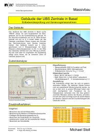
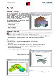
a total of over 30,000 licences used worldwide in over 150 countries<br />
Largest CAE Software Developer in Civil Engineering<br />
Branch Offices<br />
Shenyang<br />
MIDAS<br />
(Seoul)<br />
Taiwan<br />
Japan<br />
(Tokyo)<br />
Sales Offices<br />
KOZO KEIKAKU ENGINEERING<br />
ITOCHU Techno-Solutions<br />
JIP Techno Science<br />
CREA-TEC<br />
Cybernet Systems<br />
Advanced Nonlinear and Detail Analysis System Global NetworkModelling, Integrated Design & Analysis Software<br />
1
Advanced Nonlinear and Detail Analysis System<br />
<strong>midas</strong> <strong>FEA</strong> About <strong>midas</strong> <strong>FEA</strong><br />
05.<br />
Reliable<br />
MIDAS Quality Control System (MQCS)<br />
Certification for ISO 9001<br />
Verifications Examples<br />
Responsive user support<br />
04.<br />
Practical<br />
Evaluation of results<br />
Intuitive Construction Stage Definition<br />
Analysis Control<br />
Report Generation<br />
01.<br />
Unique<br />
Distinct and sophisticated visual interface<br />
Versatile representations of analysis results<br />
Powerful geometry modelling capabilities<br />
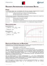
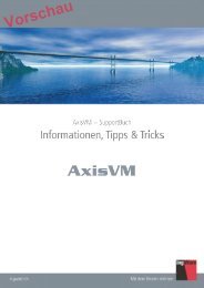
<strong>Why</strong><br />
<strong>midas</strong> <strong>FEA</strong>?<br />
03.<br />
Powerful<br />
Advanced Nonlinear and Detail Analysis System<br />
<strong>midas</strong> <strong>FEA</strong> is state of the art software, which defines a new paradigm for advanced nonlinear and detail analysis for civil and<br />
structural engineering applications including plain and reinforced concrete structures, concrete damage and cracking, plain and<br />
reinforced masonry structures, composite structures, steel structures, foundations, and offshore structures.<br />
<strong>midas</strong> <strong>FEA</strong>, combining a powerful pre/post processor and solvers stands for reliability and accurate solutions and is founded on<br />
expertise in geometry modelling, Auto-mesh generation, contemporary graphics and analysis technologies.<br />
02.<br />
Easy<br />
Intuitive Framework<br />
Task-oriented User Interface<br />
Modelling complex 3D geometries<br />
Automatic Mesh Generation<br />
Mesh manipulation<br />
Numerous Analysis Features<br />
Static and Dynamic Load and Boundary Conditions<br />
Unprecedented Fast Analysis Speed<br />
2
Advanced Nonlinear and Detail Analysis System<br />
<strong>midas</strong> <strong>FEA</strong> Application Areas<br />
01. Linear Static Analysis<br />
Multiple Load Cases & Combinations<br />
Output Control (Data, Node, Element)<br />
Result Coordinate System<br />
Extensive Element Library<br />
Equation Solvers<br />
- Direct Solvers<br />
Multi-frontal Sparse Gaussian Solver<br />
Skyline Solver<br />
- Iterative Solvers<br />
PCG, GMR (Unsymmetric)<br />
Construction Stage Analysis<br />
- Material Nonlinearity<br />
- Restart<br />
04. Reinforcement Analysis<br />
Reinforcements<br />
- Embedded Bar<br />
- Embedded Grid<br />
- Various Mother Elements<br />
(Solid, Plate, Axisymmetric, etc.)<br />
Post tensioned Prestress<br />
Material Nonlinearity<br />
Geometric Nonlinearity<br />
02. Eigenvalue Analysis<br />
Modal Analysis<br />
- Lanczos Method<br />
- Subspace Iteration<br />
- Sturm-Sequence Check<br />
- Include Rigid Body Modes<br />
- Modal Participation Factors<br />
Linear Buckling Analysis<br />
- Critical Load Factors<br />
- Buckling Modes<br />
- Load Combinations & Factors<br />
05. Heat of Hydration Analysis<br />
Heat Transfer<br />
- - Steady-State / Transient<br />
- - Heat Generation<br />
- - Conduction<br />
- - Convection<br />
- - Pipe Cooling<br />
Concrete Behaviour<br />
Behavior<br />
- - Creep / / Shrinkage<br />
- - Compressive Strength<br />
- - Design Codes (JCI, JSCE, etc.)<br />
Parametric Analysis<br />
- - Mutiple Material Sets<br />
- - Multiple BCs & Heat Sources<br />
- - Multiple Construction Sequences<br />
Advanced Nonlinear and Detail Analysis System<br />
03. Dynamic Analysis<br />
Transient / Frequency Response<br />
- Direct Integration<br />
- Mode Superposition<br />
- Time Forcing Function DB<br />
- Time Varying Loads<br />
- Ground Acceleration<br />
- Time History Plot / Graph<br />
Spectrum Response<br />
- SRSS, CQC, ABS<br />
- Design Spectrum DB<br />
- Seismic Data Generator<br />
06. Interface Nonlinearity Analysis<br />
Interface Elements<br />
- Point, Line, Plane<br />
- Pile (Solid-Line)<br />
Interface Models<br />
- Rigid<br />
- Coulomb Friction<br />
- Discrete Cracking<br />
- Crack Dilatancy<br />
- Bond-Slip<br />
- Combined CSC<br />
3
Advanced Nonlinear and Detail Analysis System<br />
<strong>midas</strong> <strong>FEA</strong> Application Areas<br />
07. Contact Analysis<br />
Contact Type<br />
- Weld Contact, General Contact<br />
Behaviour<br />
- Material Nonlinearity<br />
- Geometry Nonlinearity<br />
Results<br />
- Displacement<br />
- Stress<br />
- Contact force<br />
10. Fatigue Analysis<br />
Methods and Parameters<br />
- S-N Method (Stress-Life)<br />
- E-N Method (Strain-Life)<br />
- Load / Stress History<br />
- Rainflow Counting<br />
- Mean Stress Corrections<br />
- Stress Concentration Factor<br />
- Modifying Factors<br />
Results<br />
- Cycles to Failure<br />
- Safety Factor<br />
(Cycles to Failure /<br />
Desired Repetition)<br />
- Damage estimation<br />
08. Nonlinear Static Analysis<br />
Material Nonlinearity<br />
- von Mises, Tresca, Mohr-Coulomb,<br />
Drucker-Prager, Rankine,<br />
User Supplied Material<br />
Geometric Nonlinearity<br />
- Total Lagrangian, Co-rotational<br />
Iteration Method<br />
- Full Newton-Raphson, Modified<br />
Newton-Raphson, Arc-Length Method,<br />
Initial Stiffness<br />
11. Heat Transfer/Stress Analysis<br />
Steady-State & Transient<br />
Conduction, Convection<br />
Heat Flux<br />
Heat Flow<br />
Temperature Gradient Display<br />
Advanced Nonlinear and Detail Analysis System<br />
09. Cracking Analysis<br />
Total Strain Crack<br />
- Fixed & Rotating Crack Model<br />
Discrete Crack Model<br />
- Interface Nonlinearity<br />
Results<br />
- Crack Pattern<br />
- Element Status<br />
(Crack, Plasticity)<br />
12. CFD Analysis<br />
CFD Models<br />
- Turbulence Models<br />
RANS, k-, -<br />
- Compressible Flow<br />
- Incompressible Flow<br />
- Inviscid Flow<br />
- Unsteady Flow<br />
Discretisation Scheme<br />
- 2nd-order (Spatial)<br />
- Dual time stepping (Temporal)<br />
Boundary Condition<br />
- Far-field<br />
- Wall (Slip, Non-slip), etc.<br />
- Symmetric<br />
4
<strong>midas</strong> <strong>FEA</strong><br />
“Advanced Nonlinear and Detail Analysis System”<br />
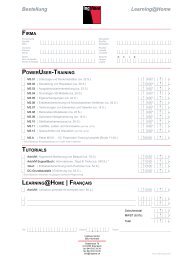
01.<br />
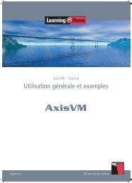
Graphical User Interface<br />
Providing an integrated and efficient work environment for<br />
Modelling, Visualisation and Simulation<br />
<strong>midas</strong> <strong>FEA</strong> - Framework<br />
Observer / Navigation Window<br />
Works Tree<br />
Main Menu<br />
Tabbed Toolbars<br />
Task Pane<br />
Quick review for both global and<br />
detail view of analysis results<br />
A new concept tool, which enables the user<br />
to freely set optimal menu system<br />
A new concept menu system comprising frequently<br />
used menus<br />
Procedural sequence defined by the user for<br />
maximum efficiency<br />
Auto-links to manuals, technical papers and tutorials<br />
Links to corresponding dialogue boxes for ease of<br />
checking input data<br />
Property Window<br />
Property Window provides various<br />
property information for quick query/edit.<br />
Customise detailed graphic output for<br />
result generation<br />
Output Window<br />
Status Bar<br />
Context Menu<br />
5 Modelling, Integrated Design & Analysis Software
<strong>midas</strong> <strong>FEA</strong><br />
“Advanced Nonlinear and Detail Analysis System”<br />
02.<br />
Pre Processor<br />
The powerful pre-processor is founded on the expertise<br />
in geometry modelling, auto-mesh generation and powerful 3D graphic tools<br />
Display Mode<br />
Geometry Modelling<br />
Geometry Display Mode Local Prism Stitch to Solid<br />
<br />
<br />
<br />
<br />
Wireframe Transparency Shading<br />
Forming a solid model by extracting specific surface<br />
Forming a solid model by sewing surfaces<br />
Mesh Display Mode<br />
Sweep<br />
Loft & Extrude<br />
<br />
<br />
<br />
<br />
<br />
<br />
Feature Edge<br />
Transparency<br />
Shading<br />
<br />
Extrude along guide curve<br />
Create a solid model with<br />
variation of cross section (Tapered section)<br />
Customisation controls to easily view geometry or mesh sets<br />
Full graphics control for geometry and mesh sets<br />
Full graphics control to view interior shapes embedded in complex structures by<br />
transforming to wireframe, or control transparency for local/global parts of the model<br />
Perform the Boolean operation (Fuse, Cut, Embed) for geometry compatibility with<br />
more than two solid objects<br />
Using advanced geometry tools (Loft, Sew, Sweep, Local Prism) to convert<br />
2D geometry models to 3D geometry shapes<br />
Modelling, Integrated Design & Analysis Software<br />
6
<strong>midas</strong> <strong>FEA</strong><br />
“Advanced Nonlinear and Detail Analysis System”<br />
02.<br />
Pre Processor<br />
The powerful pre-processor is founded on the expertise<br />
in geometry modelling, auto-mesh generation and powerful 3D graphic tools<br />
Mesh Generation<br />
Automatic Surface/Solid Meshing<br />
Revolve Mesh<br />
Sweep Mesh<br />
Surface Automatic Mesh<br />
<br />
<br />
Automatically generate solid mesh by rotating<br />
2D-Mesh using reference axis<br />
Fill Mesh<br />
Automatically generate solid mesh by<br />
extruding 2D-Mesh using guide curve<br />
Project Mesh<br />
Solid Automatic Mesh<br />
<br />
<br />
<br />
<br />
Fill mesh creates 3D mesh sets between<br />
two 2D mesh shapes with similar element<br />
size discretisation.<br />
Automatically generate mesh by projecting<br />
a mesh on a reference plane<br />
Includes advanced meshing function : Auto-Mesh, Map-mesh & manual generation<br />
Mesh extraction method from 2D/3D mesh sets or directly from a geometry object<br />
Capability of generating 3D mesh for complex shapes using 2D Mesh sets<br />
Supports advanced meshing functions for complex geometry modelling : Manifold and<br />
non-manifold shapes<br />
Provides advanced mesh function such as Hybrid Meshing, Sub-Meshing as well as<br />
Auto-mesh, Map-mesh<br />
Fast mesh generation: 200,000 tetra elements per-minute<br />
7 Modelling, Integrated Design & Analysis Software
<strong>midas</strong> <strong>FEA</strong><br />
“Advanced Nonlinear and Detail Analysis System”<br />
02.<br />
Pre Processor<br />
The powerful pre-processor is founded on the expertise<br />
in geometry modelling, auto-mesh generation and powerful 3D graphic tools<br />
Mesh Size Control/Quality Assurance<br />
Frame to Solid (Direct Data Transfer with <strong>midas</strong> Civil)<br />
Mesh Size Control<br />
<br />
<br />
Mesh Quality Assurance<br />
Check & Verify<br />
- Free Edges<br />
- Free Faces<br />
- Manifold Edges<br />
- Non-manifold Edges<br />
- Check & Align ECS<br />
Quality Assurance<br />
- Aspect Ratio<br />
- Skew Angle<br />
- Taper (2D)<br />
- Warpage (2D)<br />
- Jacobian Ratio<br />
- Twist<br />
- Collapse (Tetra)<br />
- Length / Area<br />
Mesh Size Control<br />
Check Free Face<br />
Mesh Quality Plot<br />
Automatically imported solid models<br />
into <strong>midas</strong> <strong>FEA</strong><br />
Frame model in <strong>midas</strong> Civil<br />
Detailed model conversion for PSC Box sections including tendon profiles<br />
Automatically imported plate model in<br />
<strong>midas</strong> <strong>FEA</strong><br />
Various size control functions available to modify density of nodes and elements for<br />
complex geometry or variation of material properties<br />
Advanced size control functions such as Adaptive Seeding, which automatically controls<br />
mesh density based on shape characteristics<br />
Standard Mesh quality and assurance features to detect incompatibility or poor element quality<br />
Convert frame model and PSC section types in <strong>midas</strong> Civil into plate/solid models in <strong>midas</strong> <strong>FEA</strong><br />
Convert tendon profiles and embed them as bars from <strong>midas</strong> Civil into <strong>midas</strong> <strong>FEA</strong><br />
Modelling, Integrated Design & Analysis Software<br />
8
<strong>midas</strong> <strong>FEA</strong><br />
“Advanced Nonlinear and Detail Analysis System”<br />
03.<br />
Analysis<br />
Providing high-end linear/nonlinear analysis<br />
capabilities optimised for bridge and structural engineering<br />
Linear Static Analysis<br />
Eigenvalue Analysis<br />
Linear Static Analysis<br />
Multiple Load Cases<br />
Result Combination and Transformation<br />
Modal Analysis<br />
Lanczos Method<br />
Subspace Iteration<br />
Equation Solvers<br />
Direct Solvers<br />
- Multi-frontal Sparse Gaussian Solver (Default)<br />
- Skyline Solver<br />
Iterative Solvers<br />
- Preconditioned Conjugate Gradient<br />
- Generalised Minimal Residual<br />
Plate Girder Bridge (Plate)<br />
Extradosed Bridge<br />
(1/2 Symmetric)<br />
<br />
<br />
<br />
Linear Buckling Analysis<br />
Steel Box Girder – Inner Support<br />
Critical Buckling Modes<br />
Buckling Modes<br />
Regulatory Load Combinations<br />
Model A Model B Model C Model D<br />
<br />
<br />
<br />
<br />
<br />
<br />
<br />
<br />
<br />
<br />
<br />
<br />
<br />
<br />
<br />
<br />
<br />
<br />
<br />
<br />
<br />
<br />
<br />
<br />
<br />
<br />
<br />
<br />
<br />
Net Solution time: Intel® Core Duo CPU @ 3GHz 2GB RAM<br />
Saddle at the Top of an Extradosed Bridge (Soiid)<br />
Steel Box Diaphragm<br />
(1/2 Symmetric)<br />
<br />
Fast and accurate analysis by using Multi-frontal Sparse Gaussian Solver<br />
Various load and boundary conditions (Applied load at any position, Distributed load<br />
for live/dead load, Multi Point Constraint etc.)<br />
Accurate analysis using higher order elements<br />
Eigenvalue Analysis : Lanczos Method & Subspace Iteration Method<br />
Generate load combination for buckling analysis<br />
Output buckling mode shape which has positive critical load factor (Option)<br />
Removing unnecessary buckling modes<br />
9 Modelling, Integrated Design & Analysis Software
<strong>midas</strong> <strong>FEA</strong><br />
“Advanced Nonlinear and Detail Analysis System”<br />
03.<br />
Analysis<br />
Providing high-end linear/nonlinear analysis<br />
capabilities optimised for bridge and structural engineering<br />
Dynamic Analysis<br />
Static Nonlinear Analysis<br />
Transient Response Analysis<br />
Direct Transient Response<br />
Modal Transient Response<br />
Time Forcing Function DB<br />
(54 Earthquake Acceleration<br />
Records)<br />
Material Models<br />
von Mises<br />
Tresca<br />
Mohr-Coulomb<br />
Drucker-Prager<br />
Rankine<br />
User-Supplied Material<br />
Failure Criteria<br />
Tresca<br />
Von-Mises<br />
Mohr-Coulomb<br />
Spectrum Response Analysis<br />
SRSS, CQC, ABS<br />
Design Spectrum DB<br />
Design Spectrum<br />
Seismic Wave<br />
Material Nonlinearity<br />
Hardening (Isotropic)<br />
Softening<br />
Rankine<br />
Drucker-Prager<br />
Geometric Nonlinearity<br />
Iteration Methods<br />
Total Lagrangian<br />
Response to the<br />
Longitudinal Seismic Force<br />
Response to the<br />
Transverse Seismic Force<br />
Iteration Methods<br />
Full Newton-Raphson<br />
Modified Newton-Raphson<br />
Arc-Length Method<br />
Initial Stiffness<br />
Initial Stiffness<br />
Newton-Rahpson<br />
Modified Newton<br />
-Rahpson<br />
Arc-Length<br />
Integral Bridge Modeling<br />
Acceleration at the Top of the Pier<br />
Supports the design response spectrum based on seismic database library<br />
Provides time history analysis by Direct Integration Method and Modal Time History Analysis<br />
Produces various time history analysis result graphs : nodal displacement/speed/acceleration,<br />
member force stress/strain of element<br />
Include a total of five constitutive models in addition to an user supplied material option for<br />
all types of material models including concrete and steel<br />
Consider effects of transverse varying stiffness and large deformation for structures<br />
undergoing material nonlinearity effects and large axial forces (Frame, Plate, and Solid models)<br />
Consider geometry and material nonlinear analysis simultaneously for frame,<br />
plate and solid elements<br />
Iterative analysis techniques : Initial Stiffness, Modified/Newton-Raphson, and Arc-Length<br />
Auto load step and restart options<br />
Modelling, Integrated Design & Analysis Software<br />
10
<strong>midas</strong> <strong>FEA</strong><br />
“Advanced Nonlinear and Detail Analysis System”<br />
03.<br />
Analysis<br />
Providing high-end linear/nonlinear analysis<br />
capabilities optimised for bridge and structural engineering<br />
Reinforcement Analysis<br />
Cracking Analysis<br />
Reinforcements (Rebar & Tendon)<br />
Embedded Bar/Grid<br />
Line Type Applied to Plate, Solid & Plain Stress<br />
Point Type Applied to Plain Strain & Axisymmetric<br />
<br />
Prestressing Tendon<br />
Pretension & Post-Tension<br />
Short-Term Loss: Friction, Slip & Elastic Deformation<br />
Long-Term Loss: Relaxation & Creep/Shrinkage<br />
Loss of Pretension<br />
Column Reinforcements of an Underground Station<br />
Cracking Models<br />
Total Strain Crack<br />
- Fixed Crack Model & Rotating Crack Model<br />
Discrete Crack Model<br />
- Interface Nonlinearity<br />
Results<br />
Crack Pattern (Crack Stress/Strain)<br />
Element Status<br />
- Cracking: Partially/Fully Open, Closed, Not Yet<br />
- Plasticity: Previously Plastic, Elastic, Plastic, Critical<br />
- Contact: No Contact, Slip, Stick<br />
PSC Box<br />
Load Step 1<br />
PSC Box<br />
Load Step 5<br />
1. tensioning<br />
limited penetration<br />
Prestressing Tendons in a PSC Box Bridge<br />
Concrete Crack Models<br />
Disc Normal: Opening Direction<br />
Disc Color: Magnitude<br />
Line: Shearing Direction<br />
tendon<br />
2. penetration at 1<br />
tendon<br />
3. penetration at 2<br />
tendon<br />
Discrete Crack<br />
Smeared Crack<br />
<br />
Unique embedded techniques enable users to model tendons and reinforcement<br />
regardless of neighbouring elements and nodal connectivity<br />
Analyses considering immediate loss (friction, slip and elastic deformation) and longterm<br />
loss (tendon relaxation, creep/shrinkage effect)<br />
Includes TSC (Total Strain Crack) for concrete crack analysis: Fixed and Rotating models<br />
Includes Reinforcement Analysis to portray the main concrete tension reinforcement<br />
Incorporates impact of rebar in tensile behaviour of concrete structures<br />
Includes analysis results and visualisation of crack pattern, direction and status of the element<br />
11 Modelling, Integrated Design & Analysis Software
<strong>midas</strong> <strong>FEA</strong><br />
“Advanced Nonlinear and Detail Analysis System”<br />
03.<br />
Analysis<br />
Providing high-end linear/nonlinear analysis<br />
capabilities optimised for bridge and structural engineering<br />
Heat Transfer Analysis<br />
Heat of Hydration Analysis<br />
Heat Transfer<br />
Fire in an Underground Structure<br />
Visco-Elastic Models<br />
Steady-State & Transient<br />
Conduction, Convection<br />
Heat Flux<br />
Heat Flow<br />
Temperature Gradient Display<br />
Creep-Shrinkage (Design Code)<br />
Temperature-Dependent Material<br />
Heat Transfer<br />
Steady-State & Transient<br />
Conduction, Convection<br />
Pipe Cooling<br />
Creep/Shrinkage Function<br />
Case I<br />
Parametric Analysis<br />
Guss Asphalt Pavement<br />
Temperature of Fire<br />
Multiple Material Sets<br />
Multiple BCs & Heat Sources<br />
Multiple Construction Sequences<br />
Heat Source Function<br />
Case II<br />
Modelling Case Analysis<br />
<br />
<br />
Temperature at<br />
the Top Plate<br />
<br />
<br />
<br />
<br />
<br />
<br />
<br />
<br />
<br />
<br />
<br />
<br />
<br />
<br />
<br />
<br />
<br />
Thermal Stress<br />
Temperature Distribution<br />
Process of Parametric Analysis<br />
Parametric Analysis Control<br />
Determine the time-dependent temperature distribution and heat transfer<br />
characteristics for structures exposed to high temperatures<br />
Thermal stress analysis considering heat transfer phenomenon such as conduction, convection<br />
Perform linear analysis considering the variance in material's characteristics<br />
(intensity, specific heat, conductivity) with respect to temperature<br />
Heat transfer analysis by convection, conduction of concrete hydration heat and<br />
Thermal stress analysis which considers creep/dry shrinkage<br />
Perform creep/dry shrinkage and heat transfer analysis: heat of hydration and thermal coefficient<br />
Use general data to perform a parametric analysis<br />
Model high order elements to obtain accurate results (output result: nodal temperature,<br />
nodal displacement, element stress/strain, heat flux, heat flow, temperature gradient display,<br />
crack index)<br />
Modelling, Integrated Design & Analysis Software<br />
12
<strong>midas</strong> <strong>FEA</strong><br />
“Advanced Nonlinear and Detail Analysis System”<br />
03.<br />
Analysis<br />
Providing high-end linear/nonlinear analysis<br />
capabilities optimised for bridge and structural engineering<br />
Interface Nonlinear Analysis<br />
Static Contact Analysis<br />
Interface Models<br />
Contact Types<br />
Coulomb Friction<br />
Discrete Cracking<br />
Crack Dilatancy<br />
Bond-Slip<br />
Combined (Cracking-Shearing-Crushing)<br />
Steel-Concrete<br />
Composite Girder<br />
Weld Contact<br />
General Contact<br />
Behaviour<br />
Material Nonlinearity<br />
Geometry Nonlinearity<br />
Plate<br />
Contact<br />
Boundary<br />
Bolts<br />
Steel<br />
Results<br />
Interface<br />
Displacement<br />
Stress<br />
Contact Force<br />
Concrete<br />
Concrete Block<br />
Interface<br />
Steel Bar<br />
Displacement<br />
Stress<br />
Interface Stress<br />
Solid Stress<br />
Simulates frictional behaviour for heterogeneous material such as reinforced concrete, etc.<br />
Provides 5 interface models to describe nonlinear behaviour of heterogeneous material<br />
at contact surfaces<br />
Interface Model: Coulomb Friction, Discrete Cracking, Crack Diatancy, Bond-slip,Combined<br />
(Cracking-Shearing-Crushing)<br />
Perform contact analysis for structural parts (joint & connections) to simulate connections,<br />
cyclic loadings and contact frequency (Considering linear and nonlinear material models)<br />
Penalty method assigned for springs between contact surface and node<br />
13 Modelling, Integrated Design & Analysis Software
<strong>midas</strong> <strong>FEA</strong><br />
“Advanced Nonlinear and Detail Analysis System”<br />
03.<br />
Analysis<br />
Providing high-end linear/nonlinear analysis<br />
capabilities optimised for bridge and structural engineering<br />
Fatigue Analysis<br />
CFD (Computational Fluid Dynamics) Analysis<br />
Methods and Parameters<br />
S-N Method (Stress-Life)<br />
E-N Method (Strain-Life)<br />
Load / Stress History<br />
Rainflow Counting<br />
Mean Stress Corrections<br />
Stress Concentration Factor<br />
Modifying Factors<br />
Calculation Objects<br />
Boundary Nodes Only (Default)<br />
Nodes of Selected Mesh Sets<br />
Results<br />
Cycles to Failure<br />
Safety Factor<br />
(Cycles to Failure / Desired<br />
Repetition)<br />
Linear Analysis<br />
Rainflow Counting & S-N Curve<br />
Stress Amplitude<br />
CFD Models<br />
Turbulence Models<br />
(RANS, k-, q-)<br />
Compressible Flow<br />
Incompressible Flow<br />
Inviscid Flow<br />
Unsteady Flow<br />
Discretisation Scheme<br />
2nd-order (Spatial)<br />
Dual time stepping (Temporal)<br />
Boundary Condition<br />
Far-field<br />
Wall (Slip, Non-slip), etc.<br />
Velocity contour<br />
CFD model= Bridge Section<br />
Pressure contour<br />
Vorticity contour<br />
Damage<br />
Life Cycle<br />
Fatigue Analysis: Display structure failure phenomenon based on a cyclic loading<br />
pattern with reduced yield strength<br />
Calculate stress amplitude Applying Rainflow Counting & S-N Curve Calculating<br />
the fatigue life (life cycle) and extent of damage<br />
Investigate bridge’s stability resistance to wind by visually determining airflow pattern<br />
Perform Steady state analysis / Unsteady analysis and Laminar Flow /<br />
Turbulence Flow analysis<br />
Calculate aerodynamic force coefficients and determine pressure distribution &<br />
turbulence kinetic energy<br />
Modelling, Integrated D esign & A nalysis Software<br />
14
<strong>midas</strong> <strong>FEA</strong><br />
“Advanced Nonlinear and Detail Analysis System”<br />
04.<br />
Post Processor<br />
Providing practical output functions and<br />
effective result visualisation for analysing structure behaviour<br />
Type of Plots / Interactive Legend Control<br />
Extract Result / Probe Result<br />
Iso Surface Plot<br />
Clipping Plot<br />
Illustrate cross-sectional results by<br />
defining cutting surfaces.<br />
Legend Control<br />
Full control on legend to<br />
modify range of output results.<br />
Probe Result<br />
Display tagged results on<br />
selected nodes or elements<br />
Original Plot<br />
Mirror Plot<br />
Illustrate full scale results for symmetry models<br />
Hybrid Plot<br />
Illustrate contour plot and<br />
vector plot simultaneously.<br />
Slice Plot<br />
Check results using defined plane slices<br />
for viewing localised behaviour.<br />
Extract results in a table<br />
Extract Result<br />
Extract Result enables to output<br />
only desired data from the analysis results<br />
Load-Displacement graph<br />
Intuitive graphical output functions to verify and illustrate the analysis results<br />
Control range of contour or colour spectrum with Legend Control function<br />
Extract Results: Extract results directly from nodes or elements for all the stages<br />
Probe Results: Display tags on nodes or elements with corresponding results<br />
Easily filter Min or Max results using Probe Results<br />
15 Modelling, Integrated Design & Analysis Software
<strong>midas</strong> <strong>FEA</strong><br />
“Advanced Nonlinear and Detail Analysis System”<br />
04.<br />
Post Processor<br />
Providing practical output functions and<br />
effective result visualisation for analysing structure behaviour<br />
On Curve Diagram / Local Direction Force Sum<br />
Virtual Transformation<br />
On Curve Diagram<br />
Integral Bridge<br />
Deck<br />
Diaphragm<br />
Local Direction Force Sum<br />
Plate Stress<br />
Abutment<br />
Pier<br />
Girder<br />
Local Direction Force Sum<br />
<br />
Pier<br />
Abutment<br />
Extract results from two user-defined points or acurve to display output diagram and table<br />
Local Direction Force Sum – Extract member force or moment results at a specific section<br />
Intuitive tools to investigate the interior parts of a complex model based on virtual<br />
transformation of mesh sets<br />
Modelling, Integrated Design & Analysis Software<br />
16
<strong>midas</strong> <strong>FEA</strong><br />
“Advanced Nonlinear and Detail Analysis System”<br />
05.<br />
Applications<br />
Specialised application cases for civil engineering<br />
Detailed Analysis of Steel Box Girder & Coping Connection<br />
Detailed analysis for concrete structures – Stress concentration analysis<br />
Geometry Modelling<br />
Detailed review of tendon anchorage<br />
Detailed analysis effects for cables installed on bridge saddle<br />
Geometry Modelling<br />
Steel Box Girder Modelling<br />
Geometry Modelling<br />
Steel Coping<br />
Modelling<br />
Results<br />
Geometry Modelling<br />
Contour Plot<br />
Analysis Results<br />
Detailed review of Anchorage block<br />
Stress at Connections<br />
Displacement Contour<br />
Strain at Connections<br />
Geometry Modelling Contour Plot Slice Plot<br />
Perform linear static analysis for connection between steel box girder and coping<br />
Review stress distribution resultant from bending moment and torsion at cross sectional diaphragms<br />
Define rigid diaphragm nodes at cut end boundaries of the structure<br />
Perform linear static analysis for stress concentration for anchorage block<br />
Review tensile stress and bursting stress for zones with high stress concentrations<br />
(tendon, cable anchor and suspension bridge saddle)<br />
17 Modelling, Integrated Design & Analysis Software
<strong>midas</strong> <strong>FEA</strong><br />
“Advanced Nonlinear and Detail Analysis System”<br />
05.<br />
Applications<br />
Specialised application cases for civil engineering<br />
3D FEM Analysis for Long-span FSM Bridge<br />
Detailed Behaviour for 1 pylon Extradosed Bridge<br />
Geometry Modelling<br />
Construction Stage 3<br />
Construction<br />
Stage 2<br />
Construction Stage 1<br />
Displacement Contour<br />
Solid Geometry<br />
Construction Stage Analysis<br />
Tendon placing<br />
Construction Stage<br />
On-curve diagram<br />
(longitudinal stress)<br />
Construction Stage<br />
for 30 days<br />
Construction Stage<br />
for 30 days<br />
Global Model of<br />
Extradosed Bridge<br />
Construction Stage<br />
for 60 days<br />
Construction Stage<br />
for 60 days<br />
Prestress forces at tendons<br />
Stress distribution<br />
(pylon)<br />
Construction Stage<br />
for 90 days<br />
Construction Stage<br />
for 90 days<br />
Stress distribution after<br />
installing key segments<br />
Stress distribution before<br />
installing key segments<br />
Normal Stress per construction stage<br />
Tensile force per each construction stage<br />
Perform 3D FE analysis to verify the stability of a long span FSM bridge<br />
(over 70m long) with varying geometry dimensions at cross-section and top deck width<br />
Determine stress variations and tendon prestress distribution using construction stage<br />
analysis at critical sections<br />
Obtain accurate reaction distribution results at bearing points compared to frame analysis<br />
Verify transversely distributed forces of one pylon extradosed bridge<br />
Verify detailed behaviour of the BCM bridge using construction stage analysis during<br />
installation of key segment parts<br />
Modelling, Integrated D esign & A nalysis Software<br />
18
<strong>midas</strong> <strong>FEA</strong><br />
“Advanced Nonlinear and Detail Analysis System”<br />
05.<br />
Applications<br />
Specialised application cases for civil engineering<br />
Reviewing Redundancy for Plate Girder System<br />
Load Carrying Capacity Evaluation for PSC Box Bridge<br />
Modelling of Extradosed Bridge Principal Stress Radial Tendon Prestress Force<br />
Detail model of Plate Girder system<br />
von Mises Stress Plasticity<br />
Crack Analysis<br />
Load Step 1 (0.4)<br />
Load Step 4<br />
(0.5)<br />
Load Step 6<br />
(0.7625)<br />
Load Step 6 (0.75)<br />
Max Deformation vs. Load Increment Curve<br />
Load Step 16 (1.0)<br />
von Mises Stress Shape with Load Increment<br />
Crack Status<br />
Crack pattern per load step<br />
Model the redundancy effects on a plate girder bridge<br />
Simulate nonlinear behaviour of the model using von-Mises constitutive model and<br />
Newton-Raphson iterative method<br />
Monitor failure mechanism based on ultimate state of nonlinear material models<br />
Behavioural characteristic results different from elastic analysis can be caused by<br />
material nonlinearity in the case of actual structure in extreme conditions<br />
Evaluate stress condition considering the nonlinearity of the ultimate condition<br />
Determine crack pattern and status for concrete crack analysis applying<br />
TSC (Total Strain Crack) model<br />
19 Modelling, Integrated Design & Analysis Software
<strong>midas</strong> <strong>FEA</strong><br />
“Advanced Nonlinear and Detail Analysis System”<br />
05.<br />
Applications<br />
Specialised application cases for civil engineering<br />
Application for Heat of Hydration Analysis Using Parametric Analysis Feature<br />
Contact Analysis of Bolt Connection<br />
Selecting Hydration Analysis Model and Parameter Analysis Result for each Parameter Overview of Analysis model<br />
<br />
<br />
<br />
<br />
<br />
<br />
<br />
<br />
<br />
<br />
<br />
<br />
<br />
<br />
<br />
<br />
<br />
<br />
Heat Function<br />
Application<br />
<br />
<br />
<br />
<br />
<br />
<br />
Heat<br />
Distribution<br />
<br />
Geometry Modelling<br />
<br />
<br />
<br />
<br />
<br />
<br />
<br />
<br />
Bolt Connection of Web Plate on the Steel Bridge<br />
Base plate and Bolt Modelling (1/8 model)<br />
<br />
<br />
<br />
<br />
<br />
<br />
Case 2 Case 3 Case 4<br />
Substrate and<br />
connection plate<br />
Deformed Shape<br />
Heat Function<br />
Application<br />
Heat Function<br />
Application<br />
Heat Function<br />
Application<br />
Defining contact<br />
surface<br />
Heat<br />
Distribution<br />
Heat<br />
Distribution<br />
<br />
<br />
Bolt<br />
Stress of contact surface<br />
Model Configuration for Contact Analysis<br />
Contact Analysis Results<br />
Perform analysis consisting of cases for various factors<br />
(casting, convection boundary, material. thermal characteristics, self-weight) for<br />
controlling heat of hydration effect in a model<br />
Select casting height and material parameters through parametric analysis for<br />
finding crack index range<br />
Define contact surface between base plate, gusset plate and bolts to transfer contact forces<br />
Perform nonlinear analysis considering contact condition between members<br />
Penalty method is applied in order to intercept the interaction of the contact surface based<br />
on spring elements<br />
Modelling, Integrated Design & Analysis Software<br />
20
<strong>midas</strong> <strong>FEA</strong><br />
“Advanced Nonlinear and Detail Analysis System”<br />
05.<br />
Applications<br />
Specialised application cases for civil engineering<br />
Fatigue Analysis for Steel Bridge<br />
Thermal Stress Examination According to the Guss Asphalt Construction<br />
Fatigue Analysis<br />
Heat Deformation of Steel Box Girder<br />
Heat Transfer Analysis<br />
<br />
<br />
Steel Box Girder Model<br />
Stress Amplitude According<br />
to Variable Loads<br />
(a) Limitation of horizontal reaction for<br />
steel box girder bearing<br />
<br />
<br />
Temperature distribution<br />
at 30 Min.<br />
Life Cycle<br />
Damage<br />
<br />
<br />
(b) Limitation of negative reaction for<br />
steel box girder bearing<br />
<br />
<br />
<br />
Analysis model for verification<br />
Temperature variation with time<br />
<br />
<br />
<br />
Heat Stress Analysis<br />
(c) Ensure joint gap for steel box girder bearing<br />
<br />
<br />
<br />
<br />
<br />
<br />
<br />
(d) Ensure shrinkage of joint gap for<br />
steel box girder bearing.<br />
Deformed shape according<br />
to one-sided placing<br />
Perform static analysis on structures with applied static loads and live loads to calculate<br />
the amplitude stress<br />
Set maximum amplitude stress for S-N Curve of steel box and limitation of amplitude stress<br />
Calculate fatigue life (fatigue iteration) and failure considering the influence by<br />
Mean stress correction<br />
When constructing Guss asphalt, the section of steel box temporarily generates<br />
high temperature difference<br />
When constructing previous Guss asphalt, problems arising at expansion joints or<br />
damage cases for the cross clamps depend on the vertical direction of the displacement<br />
Preparation for effective construction plan through the thermal stress examination before<br />
the Guss asphalt construction<br />
21 Modelling, Integrated Design & Analysis Software
<strong>midas</strong> <strong>FEA</strong><br />
“Advanced Nonlinear and Detail Analysis System”<br />
05.<br />
Applications<br />
Specialised application cases for civil engineering<br />
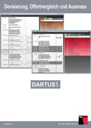
Underground station and fire analysis of tunnel<br />
Fire Analysis Concept<br />
Temperature: 25 degrees<br />
Fire Analysis Process Heat Transfer Analysis of Underground Station Heat Transfer Analysis of Tunnel Fire<br />
Basic section design<br />
Cloth: For 25 mm<br />
Temperature: 25 degrees<br />
1 hour elapsed<br />
Section design of general external<br />
forces by strength design method<br />
Temperature : 70 degrees<br />
Temperature<br />
:500 degrees<br />
Temperature : 80 degrees<br />
Exfoliation of concrete<br />
Temperature: 650 degrees<br />
Partial rupture<br />
2 hour elapsed<br />
Deformation of<br />
reinforcement<br />
4 hour elapsed<br />
Heat transfer analysis<br />
Heat transfer analysis and calculation<br />
of temperature distribution<br />
from the demanded fire time<br />
Strength reduction computation<br />
Temperature dependent strength<br />
computation <br />
Temperature: 100 degrees<br />
Section reexamination<br />
Buckling of reinforcement<br />
Temperature: 850 degrees<br />
Edge ruptured<br />
Mn calculation & examination<br />
in demanded fire time<br />
(+)Mn (+)Mmax (service load)<br />
<br />
Temperature distribution of underground station by time frame<br />
Temperature distribution of tunnel by time frame<br />
Simulate and analyse fire exposure for underground<br />
structure based on reference code<br />
Perform heat transfer analysis using temperature<br />
dependent material properties<br />
Estimate the safety factor for damaged sections<br />
exposed to fire<br />
Duration: 5 minutes<br />
Duration: 30 minutes<br />
Duration: 5 minutes<br />
Duration: 30 minutes<br />
Duration: 3 hours<br />
Duration: 1 hour<br />
Duration: 3 hours<br />
Duration: 1 hour<br />
Modelling, Integrated Design & Analysis Software<br />
22
<strong>midas</strong> <strong>FEA</strong><br />
Advanced Nonlinear and Detail Analysis System<br />
Copyright Since 1989 MIDAS Information Technology Co., Ltd. All rights reserved.<br />
www.MidasUser.com<br />
MIDAS (UK)<br />
Suite 1005, 1 Lyric Square, London W6 0NB T 020 3586 7533 F 020 3006 8855 E UKsupport@<strong>midas</strong>user.com