Vivek Asthana, Kanpur, IND - Eurotherm 2008
Vivek Asthana, Kanpur, IND - Eurotherm 2008
Vivek Asthana, Kanpur, IND - Eurotherm 2008

Create successful ePaper yourself
Turn your PDF publications into a flip-book with our unique Google optimized e-Paper software.
5th European Thermal-Sciences Conference, The Netherlands, <strong>2008</strong><br />
Abstract<br />
PERFORMANCE OF POWER PLANTS WITH HIGH<br />
TEMPERATURE CONDITIONS AT SUB-CRITICAL<br />
PRESSURES<br />
<strong>Vivek</strong> <strong>Asthana</strong> 1 and P. K. Panigrahi 2<br />
1. Panki Thermal Power Station, <strong>Kanpur</strong>, Uttar Pradesh, India<br />
2. Indian Institute of Technology, <strong>Kanpur</strong>, Uttar Pradesh, India<br />
Technology for coal fired power generation is switching over to supercritical (SC) and ultra<br />
supercritical (USC) plants which operate with steam on higher temperature and above critical<br />
pressure to produce power output at higher thermal efficiency. Due to involvement of high heat<br />
resistant material, manufacturing costs of the components for these plants are higher. High pressure<br />
designing of these components further increases the cost. An analysis has been made in this study<br />
to explore the possibilities of operating power plants with steam at same temperatures as used in SC<br />
and USC plants but at sub-critical pressures to produce the output comparable with supercritical<br />
plants on comparable thermal efficiencies as that of supercritical plants. Analysis shows that with<br />
proper selection of reheat pressure and extraction steam parameters with in technically feasible<br />
limits of design of turbine and steam piping, power plants operating on high temperature conditions<br />
at sub-critical pressures can be designed to produce output comparable with supercritical plants.<br />
Thermal efficiency of these plants will be comparable with supercritical plants. How ever these<br />
plants shall be more economical and involve low capital as compared with supercritical and ultra<br />
supercritical plants due to relatively low pressure designing of plant components. Moreover the<br />
components of these plants can be manufactured with presently developed high heat resistant<br />
materials along with better factor of safety, which will reduce maintenance cost of the plant due to<br />
lesser numbers of failures and damages of components.<br />
1. Introduction<br />
Power generation is heavily dependent on coal fired plants through out the world. These plants<br />
contribute for about 50 percent of global power generation. This dependence of power generation<br />
on coal is likely to be continued in near future also, as the coal is cheap, easily available and evenly<br />
distributed through out the world. Conventional coal fired power generating plants operate on subcritical<br />
technology with low thermal efficiency, which results in huge environmental pollution and<br />
rapid depletion of limited reserves of coal. Due to these reasons super-critical and ultra supercritical<br />
generating plants have attracted the attention of power utilities. These plants have high<br />
generating capacity on higher thermal efficiency. Presently a large number on supercritical plants<br />
are in commercial operation in many of the countries. However due to inevitable requirement of an<br />
efficient power generation, the coal fired power generation is switching over to super-critical and<br />
ultra super-critical technology from its existing phase of conventional sub-critical technology<br />
through out the world.<br />
Yamamoto et al. (2003) reported the application of heat resistant material of high creep rupture<br />
strength and high oxidation resistance up to 650 °C, which have already been developed for Boiler<br />
and turbines of ultra super critical power plants. Viswanathan (2001) discussed the materials for<br />
ultra supercritical (USC) plants to withstand up to operating steam conditions at 760 °C<br />
temperature and 35 MPa pressure, which are under development. A large number of super-critical<br />
plants with steam parameters in range of 240 bar/600 °C /600 °C are confirmed to be in commercial<br />
operation in many countries by Shigeru (2001). Ultra super critical plants with parameters in the
5th European Thermal-Sciences Conference, The Netherlands, <strong>2008</strong><br />
range of 350 bar/700 °C /720 °C or higher are under development. As reported by Alto et al.<br />
(2001), these plants are proposed to operate on net thermal efficiency of 48-52%. However due to<br />
higher present cost of heat resistant materials, as discussed by Booras (2003) and designing of<br />
components to operate on higher supercritical pressures, a large capital is involved in these plants.<br />
Steam at a given temperature on sub-critical pressures consists of more specific enthalpy as<br />
compared with steam at super-critical/ultra super-critical pressures. Possibilities of designing coal<br />
fired power plants operating at higher temperatures of the order of SC & USC plants but on subcritical<br />
pressures to provide same output as that of SC & USC plants on thermal efficiency<br />
comparable with SC & USC plants have been explored here. These plants will be more cost<br />
effective due to involvement of components designed on relatively low pressures.<br />
2. Design features<br />
Conventional sub-critical coal fired power generating units operate on Rankine cycle. These units<br />
are invariably provided with one reheat of steam up to main steam temperature at some suitable<br />
intermediate pressure and regenerative heating of condensate through five to seven numbers of<br />
regenerative feed water heaters. Three to five numbers of these heaters (called as low pressure<br />
heaters) are provided to heat the condensate before its discharge to the deaerator. Subsequent<br />
heating of condensate takes place in deaerator which is an open type heater and facilitating removal<br />
of dissolved gases from condensate. Two more feed heaters (called as high pressure heaters) are<br />
usually provided to heat the feed water in its way from discharge of boiler feed pump to the inlet of<br />
economizer. The same design configuration has universally been adopted for super-critical and<br />
ultra super-critical units also. However in some of the units double reheat arrangement of steam is<br />
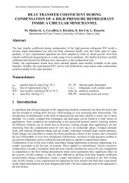
provided. Schematic of a coal fired power generating unit is shown in fig. 1, which has been<br />
analyzed here under different sub-critical and supercritical operating conditions.<br />
Fuel<br />
Input<br />
25<br />
Boiler<br />
24<br />
23<br />
6<br />
14&15<br />
22<br />
13 12<br />
K J<br />
1<br />
H P<br />
Turbine<br />
14<br />
13<br />
2<br />
I<br />
4<br />
3 5<br />
12<br />
I P<br />
Turbine<br />
G<br />
11<br />
F<br />
10<br />
9<br />
E<br />
L P Turbine<br />
8 7 15 9<br />
19<br />
D<br />
C<br />
B<br />
A<br />
20<br />
21 26<br />
Generator<br />
6<br />
H<br />
Condenser<br />
16 17 18<br />
Figure 1: Schematic of system analyzed under different operating conditions.<br />
Condensate is extracted from the condenser by means of condensate extraction pump (A) and<br />
passes through ejector (B) for heating by means of steam used in ejector for vacuum rising in<br />
condenser. Subsequently this condensate is heated in low pressure heaters (C to G) and finally<br />
stored in a feed water tank provided below the deaerator (I). The feed water is pumped to the boiler<br />
through boiler feed pump (H), which is heated on its way to boiler in high pressure heaters (J & K).
5th European Thermal-Sciences Conference, The Netherlands, <strong>2008</strong><br />
Drips collected in low pressure heaters and ejector (16, 17 & 18) is added in main condensate line<br />
(at 19). Water and steam losses from the cycle have been neglected. Thus no make-up water is<br />
assumed to be added in cycle for analysis purpose.<br />
3. Analysis<br />
To evaluate the performance of unit under different operating conditions, thermal efficiency of<br />
turbine has been worked out in accordance with following universally adopted standard relation.<br />
Energy output from Turbine (E21<br />
)<br />
ηTurbine<br />
=<br />
------------------------(1)<br />
(E + E ) − E + E + E + E + E + E + E − E )<br />
1<br />
3<br />
(<br />
2 7 8 9 10 11 12 20<br />
A portion of energy associated with turbine exhaust (6) is recovered back along with condensate<br />
(20). Hence it is also deleted along with energy associated with other extractions from total energy<br />
input (E1 + E3<br />
) to find net energy input to turbine.<br />
Thermal efficiency of boiler based on gross calorific value of coal, in accordance with following<br />
relation (equation 2), is assumed as 86% for analysis purpose. For most of the sub-critical units,<br />
which are in operation through out the world, boilers operate on approximate this value (86%) of<br />
thermal efficiency.<br />
( E24 − E23)<br />
+ ( E6<br />
− E22<br />
)<br />
η<br />
Boier<br />
=<br />
----------------(2)<br />
Fuel Energy ( associated with GCV of coal)<br />
input to Boiler (E )<br />
To evaluate thermal efficiency of unit in accordance with following relation (equation 3), generator<br />
efficiency is assumed as 98% (for most of the sub-critical units, which are in operation through out<br />
the world, generator efficiency is the same as 98%). Heat and friction losses from turbine is<br />
assumed as 2.5%. In coal fired power plants, boiler & turbine are connected through steam pipes,<br />
condensate water and feed water system. There is a net transfer of energy from boiler to turbine<br />
through above pipes & systems. Based on the data collected from a running 110 MW unit in India,<br />
as discussed in sub-section 3.3 of the paper, it is found that about 2% of the net energy being<br />
transferred from boiler to turbine is lost in above pipes & systems due to heat dissipation to<br />
surroundings. For the plants running at high temperatures, there is no change in designing of these<br />
pipes & systems except the change of material for two steam pipes only. Thus an energy loss of<br />
2% is assumed here in these pipes & systems to evaluate thermal efficiency of the unit.<br />
Power output at generator terminals ( E26<br />
)<br />
ηUnit<br />
=<br />
------------------(3)<br />
Fuel Energy ( associated with GCV of coal)<br />
input to Boiler (E )<br />
Considering above assumptions, thermal efficiency of unit is evaluated directly with the help of<br />
turbine and boiler efficiencies.<br />
3.1 Cycle analysis<br />
Expansion of steam with respect to different parameters on T-S plane is shown in fig.2. Process 1-2<br />
shows the expansion of steam in high pressure cylinder of turbine (H P turbine) in conventional<br />
sub-critical units. Switching over to super-critical parameters, expansion 3-4 provides more output<br />
on higher thermal efficiency. Instead of switching over to super-critical pressures, expansion 5-6 on<br />
same sub-critical pressure will provide enhanced output (comparing with 3-4) on relatively higher<br />
thermal efficiency. However due to higher specific volume at turbine inlet (point 5), size of turbine<br />
shall be larger comparing with sub-critical turbine (expansion 1-2). This problem is compensated<br />
25<br />
25
5th European Thermal-Sciences Conference, The Netherlands, <strong>2008</strong><br />
by adopting turbine inlet conditions at slightly higher pressures (p b instead of p a ) and selecting<br />
expansion 7-8 instead of 5-6. Specific volume of steam at point 7 is the same as that of at point 1,<br />
which provides same size of steam piping and feasible design of turbine, however with more stages<br />
and larger dimensions at end stages comparing with conventional sub-critical turbine (expansion 1-<br />
2). This expansion 7-8 provides more output comparing with output of 3-4 in super-critical units on<br />
almost same thermal efficiency. Work output obtained from H P turbine and I P & L P turbine<br />
solely depends upon the intermediate pressure selected for reheating of steam. This pressure is<br />
governed by various other design constraints also including specific volume of steam and quality of<br />
steam at the end of expansion in L P turbine at condenser pressure.<br />
p d (300 bar)<br />
p c (246 bar)<br />
T<br />
p b (142 bar)<br />
T b<br />
600ºC<br />
3<br />
7<br />
5<br />
T a<br />
535ºC<br />
1<br />
4<br />
2<br />
8<br />
6<br />
S<br />
Figure 2: Expansion of steam in turbine under sub-critical and super-critical conditions.<br />
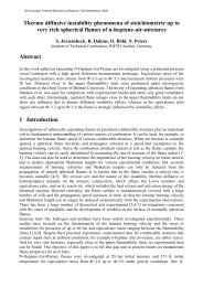
3.2 Choice of intermediate pressure for reheating of steam<br />
For conventional sub-critical units an intermediate pressure in the range of 25-45 bars has<br />
universally been adopted for reheating of steam. For most of the super-critical units, which are in<br />
operation or under development, an intermediate pressure in the range of 60-80 bars has been<br />
adopted for reheating of steam (AD 700 project). Power output and thermal efficiency of the unit<br />
depends on the choice of intermediate pressure, which is decided by various other design<br />
constraints also apart from the work output based on enthalpy drop.<br />
Output vs. IP<br />
Efficiency vs. IP<br />
Output in MW<br />
680.00<br />
660.00<br />
640.00<br />
620.00<br />
600.00<br />
580.00<br />
560.00<br />
540.00<br />
20 30 40 50 60 70 80 90 100<br />
Intermediate Pressure (IP) in bar<br />
Efficiency in %<br />
47.2<br />
47.1<br />
47<br />
46.9<br />
46.8<br />
46.7<br />
46.6<br />
20 30 40 50 60 70 80 90 100<br />
Intermediate Pressure (IP) in bar<br />
Figure 3: Variation of output and efficiency w.r.t. intermediate pressure<br />
under supercritical conditions.
5th European Thermal-Sciences Conference, The Netherlands, <strong>2008</strong><br />
An analysis has been made to demonstrate the variations in output from turbine and the variations<br />
in thermal efficiency of turbine with respect to different intermediate pressures under supercritical<br />
conditions (246 bar/600°C/600°C) and high temperature sub-critical pressure conditions (142<br />
bar/600°C/600°C) of steam.<br />
Output from turbine is evaluated neglecting the extractions from I P & L P turbines and assuming<br />
isentropic expansion of steam. Thermal efficiency of turbine is evaluated in accordance with<br />
equation 1. Variation of output and thermal efficiency with respect to different intermediate<br />
pressures under supercritical conditions is shown in fig. 3. Variation of output and thermal<br />
efficiency with respect to different intermediate pressures under high temperature condition of<br />
steam on sub-critical pressures as proposed here to design the units is shown in fig. 4.<br />
Output vs. IP<br />
Efficiency vs. IP<br />
700<br />
46<br />
Output in MW<br />
650<br />
600<br />
550<br />
Efficiency in %<br />
45.5<br />
45<br />
44.5<br />
500<br />
10 20 30 40 50 60 70 80<br />
44<br />
10 20 30 40 50 60 70 80<br />
Intermediate Pressure (IP) in bar<br />
Intermediate Pressure (IP) in bar<br />
Figure 4: Variation of output and efficiency w.r.t. intermediate pressure under high<br />
temperature condition of steam on sub-critical pressures.<br />
3.3 Analysis under different operating conditions<br />
Analysis has been made on the cycle as shown in fig. 1 with rated steam parameters for most<br />
common sub-critical unit (130 bar/535°C/535°C) of 110 MW (case A) assuming cylinder<br />
efficiencies of H P turbine, I P turbine and L P turbine as 0.90, 0.92 and 0.90 respectively as<br />
available with modern design of turbines used in USC plants. Intermediate pressure for reheating of<br />
steam is taken as 38 bar as per common design. Rated main steam flow rate has been modified to<br />
maintain the rated output, in view of assumption of higher cylinder efficiencies as compared with<br />
actual values of cylinder efficiencies for conventional sub-critical units. Output from the unit and<br />
thermal efficiency of unit has been evaluated in accordance with equations and assumptions as<br />
given in the beginning of this section.<br />
Further analysis has been made on the cycle with common conditions of commercial super critical<br />
plants as 246 bar/600°C/600°C, with same flow rates under same conditions (case-B). The cycle<br />
was subsequently analyzed considering high temperature conditions on sub-critical pressures (142<br />
bar/600°C/600°C) with same flow rates under same conditions with intermediate pressure of 38 bar<br />
(case-C). To show the benefits of selecting other technically feasible intermediate pressures for<br />
proposed steam conditions of 142 bar/600°C/600°C, subsequent analysis at intermediate pressure of<br />
15 bar has been done (Case-D). Results of analysis have been tabulated in table 1 and parameters<br />
for above analysis are given in table 2 to 5.<br />
3.4 Analysis based on exergy<br />
Exergy analysis has emerged as an effective tool in recent days to study and analyze the<br />
performance of energy conversion systems including coal power plants through pinpointing the
5th European Thermal-Sciences Conference, The Netherlands, <strong>2008</strong><br />
magnitude and quantum of irreversibilities in the system and to improve the performance of the<br />
system based on minimization of exergy losses and consumption.<br />
Quijano (2000), Kotas (1995) and Bejan et al. (1996) have beautifully defined the term “Exergy”<br />
and concept of “Exergy Analysis”. Rosen (2001) compared the working of a coal fired and a<br />
nuclear power plant based on energy and exergy. Subsequent exergy studies of conventional steam<br />
power plants by Sengupta et al. (2006) and Bandpy and Ebrahimian (2007) revealed similar<br />
results. Another important study in this field by Rosen and Dincer (2004) reported that exergy<br />
analysis is not significantly sensitive to reasonable variations in reference (dead state) properties.<br />
To perform the exergy analysis under different operating conditions (case A, B, C & D) as given in<br />
previous sub-section, the “environment” as modeled by Bejan et al. (1996) has been taken. The<br />
value of uniform temperature T o and pressure p o have been taken as that of average environmental<br />
conditions i.e. 25 o C and standard atmospheric pressure of 1.01325 bar. Physical exergies of<br />
flowing streams at different locations are evaluated with the relation Exergy =m (h - T o s) and<br />
shown in table 2 to 5. Fuel input to the boiler is evaluated in accordance with operating parameters<br />
and thermal efficiency. To evaluate exergetic efficiency of boiler, exergy (chemical exergy)<br />
associated with fuel (coal) input is calculated as per empirical relation given in text by Kotas<br />
referred above.<br />
Exergetic efficiency of unit is evaluated with the relations (1), (2) and (3) modified for Exergy<br />
(A ph ) in place of Energy (E) along with suitable assumptions as mentioned for calculation of<br />
thermal efficiency. Exergy losses & consumption in steam pipes, condensate water and feed water<br />
system is assumed as 5 % instead of 2% of heat losses as considered for calculation of thermal<br />
efficiency. The exergetic efficiencies obtained under different operating conditions are tabulated in<br />
table 1.<br />
Table 1<br />
Sl.<br />
No.<br />
4. Conclusions<br />
Different conditions of analysis<br />
Output at<br />
generator<br />
terminals<br />
(MW)<br />
Thermal<br />
Efficiency<br />
of Unit (%)<br />
Exergetic<br />
Efficiency<br />
of Unit (%)<br />
1 Sub-critical conditions (case-A) 110.54 MW 37.94 33.89<br />
2 Super-critical conditions (case-B) 131.22 MW 40.85 36.63<br />
3 high temperature conditions at sub-critical<br />
pressure with intermediate pressure of 38<br />
bar (case-C)<br />
122.11MW 39.41 34.93<br />
4 high temperature conditions at sub-critical<br />
pressure with intermediate pressure of 15<br />
bar (case-D)<br />
133.49 MW 40.09 34.92<br />
Analysis shows that higher output can be obtained with proposed design of units operating with<br />
high temperature steam on sub-critical pressures comparing with the output of supercritical units<br />
operating with same steam flow rates. Thermal efficiency of these proposed units is comparable<br />
with super critical units, which may be improved up to the efficiency of supercritical units with<br />
proper selection of design conditions. However exergy analysis reveals that these proposed units<br />
are relatively less efficient to utilize the available exergy of coal comparing with supercritical units.<br />
The units shall be more economical and cost effective comparing with super critical units due to<br />
relatively low pressure designing of plant components.
5th European Thermal-Sciences Conference, The Netherlands, <strong>2008</strong><br />
References<br />
AD 700 Project, https://projectweb.elsam-eng.com/AD700/default.aspx.<br />
Bandpy, M. J. and Ebrahimian, V., 2007, Exergy analysis of a steam power plant: a case study in<br />
Iran, Int. J. Exergy, Vol. 4, pp. 54-73.<br />
Bejan, A.; Tsatsaronis, G. and Moran, M., 1996, Thermal design and optimization, John Wiley &<br />
Sons Inc., 1996.<br />
Booras, G., Combustion technology university alliance workshop, Columbus, OH, August 4, 2003.<br />
Kotas, T. J., 1995, The exergy method of thermal plant analysis, Reprinted, Butterworths, London,<br />
1995.<br />
Quijano, J., 2000, Exergy analysis for the Ahuachapan and Berlin geothermal fields, Proc. World<br />
Geothermal Congress, Kyushu-Tohoku, Japan, May 28-June10, 2000.<br />
Rosen, M. A., 2001, Energy and exergy based comparison of coal fired and nuclear steam power<br />
plants, Exergy an Int. Journal 1 (3), pp 125-127.<br />
Rosen, M. A. & Dincer, I., 2004, Effect of varying dead-state properties on energy and exergy<br />
analysis of thermal systems, Int. J. of Thermal Sciences, 43, pp 121-133.<br />
Sengupta, S.; Gupta, S. D. and Dutta, A., 2006, Exergy analysis of a coal-based 210 MW thermal<br />
power plant, Int. J. Energy Research, Vol. 31, pp. 14-28.<br />
Shigeru Azuhata, 2001, IEEE Power Engineering Review, March 2001.<br />
Viswanathan, R., 2001, Boiler materials for ultra supercritical coal power plants, USC Materials<br />
quarterly report, EPRI Inc., Oct-Dec 2001.<br />
Viswanathan, R.; Alto, P.; Henry, J. F.; Chattanooga, A.; Tanzosh, J.; Stanko, G.; Shingledecker, J.<br />
and Weighardt, K., 2001, The advanced supercritical 700°C pulverized coal fired power plant,<br />
Powwergen Europe, Brussels, May 2001.<br />
Yamamoto, K.; Kajigaya, I. and Umaki, H., 2003, Operational Experience of USC Steam Condition<br />
Plant and PFBC Combined Cycle System with Material Performance, Materials at High<br />
Temperatures, Vol. 20, pp. 15-18.<br />
Table 2<br />
Parameters for analysis under case A<br />
Points Temp Press Flow Enthalpy Entropy Energy Exergy<br />
°C Bar Ton/Hr kJ/kg kJ/kgK kW kW<br />
1 535.0 130.00 343.00 3430 6.557 326802.78 140537.62<br />
2 351.2 38.00 343.00 3100 6.616 295361.11 107419.94<br />
3 535.0 35.00 311.50 3530 7.258 305443.06 118199.31<br />
4 2.50 2861 7.385<br />
5 2.50 2861 7.385<br />
6 41.5 0.08 211.88 2366 7.558 139252.24 6626.09<br />
7 81.8 0.51 8.96 2604 7.467 6481.07 940.09<br />
8 86.4 0.61 11.82 2629 7.456 8631.88 1333.01<br />
9 141.9 1.40 17.77 2757 7.413 13608.86 2699.13<br />
10 214.9 3.00 17.75 2896 7.375 14278.89 3437.31<br />
11 324.5 8.00 16.08 3108 7.321 13882.40 4132.76<br />
12 427.0 17.30 27.24 3311 7.285 25053.23 8618.26<br />
13 353.0 38.00 31.50 3104 6.623 27160.00 9881.83
5th European Thermal-Sciences Conference, The Netherlands, <strong>2008</strong><br />
Table 3<br />
Parameters for analysis under case B<br />
Points Temp Press Flow Enthalpy Entropy Energy Exergy<br />
°C Bar Ton/Hr kJ/kg kJ/kgK kW kW<br />
1 600.0 246.00 343.00 3495 6.371 332995.83 152014.39<br />
2 315.0 38.00 343.00 3008 6.464 286595.56 102972.26<br />
3 600.0 35.00 311.50 3678 7.434 318249.17 126464.92<br />
4 239.5 2.50 2948 7.562<br />
5 239.5 2.50 2948 7.562<br />
6 41.5 0.08 211.88 2425 7.746 142724.72 6799.59<br />
7 93.2 0.51 8.96 2669 7.649 6642.84 966.81<br />
8 107.0 0.61 11.82 2695 7.637 8848.58 1372.53<br />
9 180.3 1.40 17.77 2834 7.591 13988.94 2817.25<br />
10 258.6 3.00 17.75 2985 7.550 14717.71 3618.87<br />
11 376.3 8.00 16.08 3217 7.496 14369.27 4386.57<br />
12 486.1 17.30 27.24 3440 7.462 26029.33 9195.05<br />
13 315.0 38.00 31.50 3008 6.464 26320.00 9456.64<br />
Table 4<br />
Parameters for analysis under case C<br />
Points Temp Press Flow Enthalpy Entropy Energy Exergy<br />
°C Bar Ton/Hr kJ/kg kJ/kgK kW kW<br />
1 600.0 142.00 343.00 3589 6.709 341951.94 151368.92<br />
2 278.4 38.00 343.00 3202 6.774 305079.44 112649.96<br />
3 600.0 35.00 311.50 3678 7.434 318249.17 126464.92<br />
4 239.5 2.50 2948 7.562<br />
5 239.5 2.50 2948 7.562<br />
6 41.5 0.08 211.88 2425 7.746 142724.72 6799.59<br />
7 93.2 0.51 8.96 2669 7.649 6642.84 966.81<br />
8 107.0 0.61 11.82 2695 7.637 8848.58 1372.53<br />
9 180.3 1.40 17.77 2834 7.591 13988.94 2817.25<br />
10 258.6 3.00 17.75 2985 7.550 14717.71 3618.87<br />
11 376.3 8.00 16.08 3217 7.496 14369.27 4386.57<br />
12 486.1 17.30 27.24 3440 7.462 26029.33 9195.05<br />
13 315.0 38.00 31.50 3008 6.464 26320.00 9456.64<br />
Table 5<br />
Parameters for analysis under case D<br />
Points Temp Press Flow Enthalpy Entropy Energy Exergy<br />
°C Bar Ton/Hr kJ/kg kJ/kgK kW kW<br />
1 600.0 142.00 343.00 3589 6.709 341951.94 151368.92<br />
2 278.4 15.00 343.00 2989 6.831 284785.28 90736.59<br />
3 600.0 14.00 311.50 3695 7.871 319720.14 116662.06<br />
4 318.8 2.00 3110 7.958<br />
5 318.8 2.00 3110 7.958<br />
6 41.5 0.08 211.88 2554 8.156 150317.09 7197.36<br />
7 73.4 0.15 8.96 2636 8.118 6560.71 536.65<br />
8 111.1 0.25 11.82 2707 8.078 8887.98 980.22<br />
9 266.8 1.28 17.77 3007 7.981 14842.89 3097.24<br />
10 346.3 2.50 17.75 3165 7.946 15605.21 3924.23<br />
11 401.1 3.80 16.08 3276 7.926 14632.80 4077.46<br />
12 499.5 7.50 27.24 3480 7.896 26332.00 8518.61<br />
13 278.4 15.00 31.50 2989 6.831 26153.75 8332.95