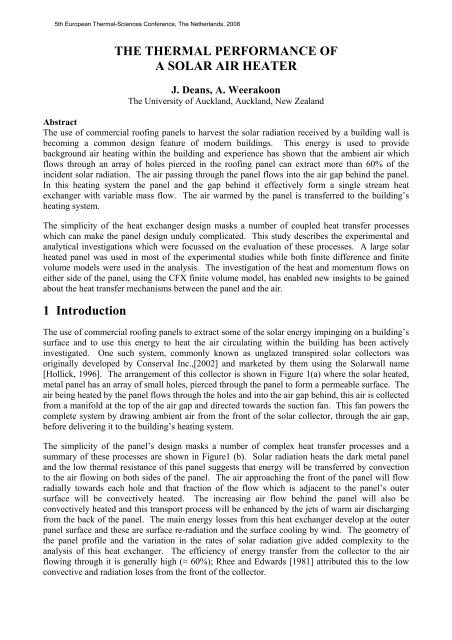
the thermal performance of a solar air heater - Eurotherm 2008
the thermal performance of a solar air heater - Eurotherm 2008
the thermal performance of a solar air heater - Eurotherm 2008

Create successful ePaper yourself
Turn your PDF publications into a flip-book with our unique Google optimized e-Paper software.
5th European Thermal-Sciences Conference, The Ne<strong>the</strong>rlands, <strong>2008</strong><br />
THE THERMAL PERFORMANCE OF<br />
A SOLAR AIR HEATER<br />
J. Deans, A. Weerakoon<br />
The University <strong>of</strong> Auckland, Auckland, New Zealand<br />
Abstract<br />
The use <strong>of</strong> commercial ro<strong>of</strong>ing panels to harvest <strong>the</strong> <strong>solar</strong> radiation received by a building wall is<br />
becoming a common design feature <strong>of</strong> modern buildings. This energy is used to provide<br />
background <strong>air</strong> heating within <strong>the</strong> building and experience has shown that <strong>the</strong> ambient <strong>air</strong> which<br />
flows through an array <strong>of</strong> holes pierced in <strong>the</strong> ro<strong>of</strong>ing panel can extract more than 60% <strong>of</strong> <strong>the</strong><br />
incident <strong>solar</strong> radiation. The <strong>air</strong> passing through <strong>the</strong> panel flows into <strong>the</strong> <strong>air</strong> gap behind <strong>the</strong> panel.<br />
In this heating system <strong>the</strong> panel and <strong>the</strong> gap behind it effectively form a single stream heat<br />
exchanger with variable mass flow. The <strong>air</strong> warmed by <strong>the</strong> panel is transferred to <strong>the</strong> building’s<br />
heating system.<br />
The simplicity <strong>of</strong> <strong>the</strong> heat exchanger design masks a number <strong>of</strong> coupled heat transfer processes<br />
which can make <strong>the</strong> panel design unduly complicated. This study describes <strong>the</strong> experimental and<br />
analytical investigations which were focussed on <strong>the</strong> evaluation <strong>of</strong> <strong>the</strong>se processes. A large <strong>solar</strong><br />
heated panel was used in most <strong>of</strong> <strong>the</strong> experimental studies while both finite difference and finite<br />
volume models were used in <strong>the</strong> analysis. The investigation <strong>of</strong> <strong>the</strong> heat and momentum flows on<br />
ei<strong>the</strong>r side <strong>of</strong> <strong>the</strong> panel, using <strong>the</strong> CFX finite volume model, has enabled new insights to be gained<br />
about <strong>the</strong> heat transfer mechanisms between <strong>the</strong> panel and <strong>the</strong> <strong>air</strong>.<br />
1 Introduction<br />
The use <strong>of</strong> commercial ro<strong>of</strong>ing panels to extract some <strong>of</strong> <strong>the</strong> <strong>solar</strong> energy impinging on a building’s<br />
surface and to use this energy to heat <strong>the</strong> <strong>air</strong> circulating within <strong>the</strong> building has been actively<br />
investigated. One such system, commonly known as unglazed transpired <strong>solar</strong> collectors was<br />
originally developed by Conserval Inc.,[2002] and marketed by <strong>the</strong>m using <strong>the</strong> Solarwall name<br />
[Hollick, 1996]. The arrangement <strong>of</strong> this collector is shown in Figure 1(a) where <strong>the</strong> <strong>solar</strong> heated,<br />
metal panel has an array <strong>of</strong> small holes, pierced through <strong>the</strong> panel to form a permeable surface. The<br />
<strong>air</strong> being heated by <strong>the</strong> panel flows through <strong>the</strong> holes and into <strong>the</strong> <strong>air</strong> gap behind, this <strong>air</strong> is collected<br />
from a manifold at <strong>the</strong> top <strong>of</strong> <strong>the</strong> <strong>air</strong> gap and directed towards <strong>the</strong> suction fan. This fan powers <strong>the</strong><br />
complete system by drawing ambient <strong>air</strong> from <strong>the</strong> front <strong>of</strong> <strong>the</strong> <strong>solar</strong> collector, through <strong>the</strong> <strong>air</strong> gap,<br />
before delivering it to <strong>the</strong> building’s heating system.<br />
The simplicity <strong>of</strong> <strong>the</strong> panel’s design masks a number <strong>of</strong> complex heat transfer processes and a<br />
summary <strong>of</strong> <strong>the</strong>se processes are shown in Figure1 (b). Solar radiation heats <strong>the</strong> dark metal panel<br />
and <strong>the</strong> low <strong>the</strong>rmal resistance <strong>of</strong> this panel suggests that energy will be transferred by convection<br />
to <strong>the</strong> <strong>air</strong> flowing on both sides <strong>of</strong> <strong>the</strong> panel. The <strong>air</strong> approaching <strong>the</strong> front <strong>of</strong> <strong>the</strong> panel will flow<br />
radially towards each hole and that fraction <strong>of</strong> <strong>the</strong> flow which is adjacent to <strong>the</strong> panel’s outer<br />
surface will be convectively heated. The increasing <strong>air</strong> flow behind <strong>the</strong> panel will also be<br />
convectively heated and this transport process will be enhanced by <strong>the</strong> jets <strong>of</strong> warm <strong>air</strong> discharging<br />
from <strong>the</strong> back <strong>of</strong> <strong>the</strong> panel. The main energy losses from this heat exchanger develop at <strong>the</strong> outer<br />
panel surface and <strong>the</strong>se are surface re-radiation and <strong>the</strong> surface cooling by wind. The geometry <strong>of</strong><br />
<strong>the</strong> panel pr<strong>of</strong>ile and <strong>the</strong> variation in <strong>the</strong> rates <strong>of</strong> <strong>solar</strong> radiation give added complexity to <strong>the</strong><br />
analysis <strong>of</strong> this heat exchanger. The efficiency <strong>of</strong> energy transfer from <strong>the</strong> collector to <strong>the</strong> <strong>air</strong><br />
flowing through it is generally high (≈ 60%); Rhee and Edwards [1981] attributed this to <strong>the</strong> low<br />
convective and radiation loses from <strong>the</strong> front <strong>of</strong> <strong>the</strong> collector.
5th European Thermal-Sciences Conference, The Ne<strong>the</strong>rlands, <strong>2008</strong><br />
PANEL<br />
Solar Radiation<br />
Radiation Loss<br />
Wind Loss<br />
AIR GAP<br />
Increasing<br />
Mass Flow<br />
Rate<br />
Internal<br />
Convection<br />
External<br />
Convection<br />
(a) Physical layout.<br />
Figure 1 Arrangement <strong>of</strong> a transpired <strong>solar</strong> collector.<br />
(b) Mass and energy flow routes.<br />
The <strong>performance</strong> <strong>of</strong> transpired <strong>solar</strong> collectors has been studied by Kutscher [1993, 1994], Van<br />
Decker [2001], Gunnewiek [1996, 2002] and Arulanandam [1999] who have conducted a wide<br />
range <strong>of</strong> experimental and computational studies. A major concern with most <strong>of</strong> <strong>the</strong>se studies is<br />
that <strong>the</strong> test geometries modelled tend to over simplify <strong>the</strong> problem and consequently, limit <strong>the</strong><br />
solution. The test rig developed by Kutscher, for example, was only a small laboratory based<br />
collector which used a flat panel and no <strong>air</strong> gap. The exclusion <strong>of</strong> <strong>the</strong> <strong>air</strong> gap from this model<br />
inherently assumes that all <strong>of</strong> <strong>the</strong> energy transfer between <strong>the</strong> panel and <strong>the</strong> <strong>air</strong> will take place from<br />
<strong>the</strong> front <strong>of</strong> <strong>the</strong> panel. These studies generally demonstrate that <strong>the</strong> <strong>the</strong>rmal <strong>performance</strong> <strong>of</strong> <strong>the</strong><br />
transpired collector is dependent on <strong>the</strong> diameter <strong>of</strong> <strong>the</strong> hole through <strong>the</strong> panel, <strong>the</strong> distance between<br />
holes, <strong>the</strong> panel thickness, <strong>the</strong> suction flow rate <strong>of</strong> <strong>the</strong> <strong>air</strong> and wind speed. The model developed to<br />
describe <strong>the</strong> interaction <strong>of</strong> <strong>the</strong>se parameters assumed that <strong>the</strong> holes effectively “harvested” <strong>the</strong><br />
<strong>the</strong>rmal boundary layer from <strong>the</strong> outer surface <strong>of</strong> <strong>the</strong> panel. Both Gunnewiek [1996, 2002] and Van<br />
Decker [2001] did however recognise that heat transfer from <strong>the</strong> panel to <strong>the</strong> <strong>air</strong> would also develop<br />
within <strong>the</strong> <strong>air</strong> gap but nei<strong>the</strong>r had <strong>the</strong> test data required to develop this alternative method.<br />
The models developed by Kutscher [1993, 1994] and Van Decker [2001] do have wide recognition<br />
but Fleck [2002] has observed that “it is quite clear from our observations that such a model is a<br />
poor descriptor <strong>of</strong> <strong>the</strong> physical phenomena driving UTSC (Unglazed Transpired Solar Collector)<br />
<strong>performance</strong>”. The paucity <strong>of</strong> test information from operational unglazed transpired <strong>solar</strong> collectors<br />
is surprising since many operating systems have been commissioned, <strong>the</strong> only studies on large<br />
collectors are those published by Carpenter [1991] Fleck [2002] and Weerakoon 2006]. The test<br />
programme <strong>of</strong> Weerakoon [2007] examined <strong>the</strong> <strong>performance</strong> <strong>of</strong> transpired <strong>solar</strong> heated collectors<br />
constructed from standard size ro<strong>of</strong>ing panels and was directed towards <strong>the</strong> determination <strong>of</strong> <strong>the</strong><br />
effects which <strong>the</strong> main design variables had on <strong>the</strong> panel’s <strong>performance</strong>.<br />
2 Experiment set-up<br />
The main test rig was constructed to accommodate a standard 2.0m * 0.8m corrugated metal ro<strong>of</strong>ing<br />
panel that could be used as <strong>the</strong> <strong>solar</strong> collector. The complete test facility is shown in Figure 2<br />
where <strong>the</strong> panel was mounted to create a small uniform, sealed gap between <strong>the</strong> panel and <strong>the</strong> wall<br />
behind. The <strong>air</strong> which migrated through <strong>the</strong> panel flowed up this gap and its depth was normally set<br />
at 20 mm. The orientation <strong>of</strong> <strong>the</strong> vertical panel could be changed but was usually north facing and<br />
located on <strong>the</strong> exposed ro<strong>of</strong> <strong>of</strong> a 20 m high building.
5th European Thermal-Sciences Conference, The Ne<strong>the</strong>rlands, <strong>2008</strong><br />
Radiometer<br />
Space bars to<br />
create cavity<br />
Outlet <strong>air</strong> manifold<br />
Solar<br />
panel<br />
Wea<strong>the</strong>r<br />
shield<br />
Solar<br />
panel<br />
Thermocouple<br />
points<br />
Wheels<br />
Data logger<br />
Back wall<br />
Linear flow element<br />
Ballast<br />
Exhaust <strong>air</strong><br />
Blower fan<br />
(a) Front <strong>of</strong> <strong>the</strong> test rig.<br />
(b) Schematic rear view <strong>of</strong> <strong>the</strong> test rig.<br />
Figure 2 The Test Facility.<br />
The <strong>air</strong> transferred through <strong>the</strong> panel was collected in <strong>the</strong> outlet <strong>air</strong> manifold shown in Figure 2(b)<br />
before it was ducted to a laminar flow element and <strong>the</strong>n to a suction fan before return to <strong>the</strong><br />
environment. A differential pressure transducer within <strong>the</strong> laminar flow element measured <strong>the</strong> <strong>air</strong><br />
flow rate through <strong>the</strong> system and calibrated platinum resistance <strong>the</strong>rmometers measured both <strong>the</strong><br />
ambient and <strong>the</strong> manifold outlet <strong>air</strong> temperatures. The incident <strong>solar</strong> radiation (İ <strong>solar</strong> ) on <strong>the</strong> metal<br />
sheet was measured using an Eppley precision radiometer and <strong>the</strong> surface temperature <strong>of</strong> <strong>the</strong> panel<br />
was monitored using an Agema Thermovision 570 infrared camera.<br />
The transpired <strong>solar</strong> collectors were constructed using 0.8mm gauge, galvanised steel, ro<strong>of</strong>ing<br />
panels. The 1.6 mm diameter holes through <strong>the</strong> panels were created using a hand drill and <strong>the</strong> panel<br />
pr<strong>of</strong>iles used in this study are shown in Figure 3. The external colours <strong>of</strong> <strong>the</strong> panels are described<br />
as iron sand and ivy green; <strong>the</strong> emissivity value for both panels was determined to be 0.88.<br />
The <strong>the</strong>rmometers were calibrated using a reference <strong>the</strong>rmometer traceable to ITS-90. The error in<br />
<strong>the</strong> <strong>the</strong>rmometer readings is believed to be less than ±0.05 o C. The calibrated charts supplied by <strong>the</strong><br />
manufacturers were used to determine <strong>the</strong> <strong>air</strong> flow rate and <strong>the</strong> level <strong>of</strong> <strong>solar</strong> radiation, <strong>the</strong><br />
uncertainty in both <strong>of</strong> <strong>the</strong>se was less than 3%. The uncertainty associated with derived values such<br />
as heat flow rates, is also estimated to be 3%. The accuracy <strong>of</strong> <strong>the</strong> infrared camera was ± 1.0 o C, but<br />
its ability to determine temperature gradients was much lower.<br />
Apriori information about <strong>the</strong> overall heat transfer coefficient for <strong>the</strong> collector panel enabled its<br />
stabilisation period to be determined and <strong>the</strong>rmal response rate calculated. In most tests <strong>the</strong> test<br />
period lasted for 60 mins and <strong>the</strong> results were not accepted during <strong>the</strong> first 15 minutes. All <strong>of</strong> <strong>the</strong><br />
tests described below were conducted on days when <strong>the</strong>re were few, if any, clouds and between <strong>the</strong><br />
hours <strong>of</strong> 10.00 am and 2.30 pm.<br />
(a) Styleline Panel. .(b) Corrugated Panel. (c) Plane Panel.<br />
Figure 3 Types <strong>of</strong> collector panel’s.
5th European Thermal-Sciences Conference, The Ne<strong>the</strong>rlands, <strong>2008</strong><br />
3 Test Results<br />
The experimental programme was structured to identify <strong>the</strong> influence which various design<br />
variables have on <strong>the</strong> collector’s <strong>performance</strong>. The general results presented in Figures 4 and 5<br />
show <strong>the</strong> influence <strong>of</strong> panel porosity, <strong>air</strong> gap depth and <strong>air</strong> suction flow rate on ei<strong>the</strong>r <strong>the</strong> overall<br />
<strong>performance</strong> <strong>of</strong> <strong>the</strong> collector or <strong>the</strong> energy transferred to <strong>the</strong> <strong>air</strong>. The influence which <strong>the</strong>se<br />
variables have on <strong>the</strong> on <strong>the</strong> design <strong>of</strong> <strong>the</strong> collector tend to support <strong>the</strong> argument that it is effectively<br />
a one stream heat exchanger.<br />
The temperature increase for <strong>the</strong> <strong>air</strong> stream passing through <strong>the</strong> panel is shown in Figure 4 where<br />
this increase is measured against <strong>the</strong> incident <strong>solar</strong> radiation and <strong>the</strong> panel’s porosity. These results<br />
were obtained for a range <strong>of</strong> collector panel porosities with a constant <strong>air</strong> mass flow rate <strong>of</strong> 0.029<br />
kg/m 2 s (based on a panel surface area) and with average wind speeds in <strong>the</strong> range 1.0 to 2 m/s. In<br />
<strong>the</strong>se tests <strong>the</strong> porosity <strong>of</strong> <strong>the</strong> panel was increased by decreasing <strong>the</strong> pitch between holes. If <strong>the</strong><br />
collector efficiency <strong>of</strong> <strong>the</strong> panel is defined as <strong>the</strong> ratio <strong>of</strong> energy extracted by <strong>the</strong> <strong>air</strong> stream and <strong>the</strong><br />
radiant energy received by <strong>the</strong> panel <strong>the</strong>n this value is effectively constant for <strong>the</strong> range <strong>of</strong> <strong>solar</strong><br />
radiation measured during <strong>the</strong>se tests. The relative unimportance <strong>of</strong> porosity is significant, since <strong>the</strong><br />
studies conducted by Kutscher [1993, 1994] and Van Decker [2001] correlated <strong>the</strong> size and <strong>the</strong><br />
spacing <strong>of</strong> <strong>the</strong> holes to <strong>the</strong> <strong>performance</strong> <strong>of</strong> <strong>the</strong> transpired <strong>solar</strong> collector.<br />
The effects which <strong>the</strong> <strong>air</strong> mass flow rate has on <strong>the</strong> <strong>performance</strong> <strong>of</strong> <strong>the</strong> plate are shown in Figure 5<br />
where <strong>the</strong> collector efficiency, increase in <strong>air</strong> temperature and <strong>the</strong> depth <strong>of</strong> <strong>the</strong> <strong>air</strong> gap are examined.<br />
These measurements were obtained using ei<strong>the</strong>r an ivy-green coloured corrugated panel or a plane<br />
ironsand coloured panel. The panel’s <strong>performance</strong> is measured in Figure 5(a) as ei<strong>the</strong>r <strong>the</strong> increase<br />
collector efficiency or a reduction in <strong>the</strong> <strong>air</strong> temperature increase when <strong>the</strong> <strong>air</strong> mass flow rate<br />
through <strong>the</strong> collector increases. This relationship evolves because <strong>of</strong> <strong>the</strong> reduction in <strong>the</strong>rmal losses<br />
from <strong>the</strong> collector when <strong>the</strong> average <strong>air</strong> temperature and <strong>the</strong> panel surface temperatures are reduced.<br />
The coupling <strong>of</strong> <strong>the</strong>se three variables permits <strong>the</strong> design <strong>of</strong> <strong>the</strong> panel to be optimised. Some<br />
confidence in <strong>the</strong> results in Figure 5(a) can be gained by extrapolating <strong>the</strong> <strong>air</strong> mass flow rates down<br />
to <strong>the</strong> values measured by Fleck (2002) who reported collector efficiencies in <strong>the</strong> range 28% to 32%<br />
when <strong>the</strong> <strong>air</strong> flow rate was 0.01 kg/m 2 s.<br />
A plain perforated panel was used in <strong>the</strong> tests which examined <strong>the</strong> influence <strong>of</strong> <strong>air</strong> gap depth behind<br />
<strong>the</strong> panel; this choice was made to ensure a well defined minimum value. The results given in<br />
Figure 5(b) show that <strong>the</strong>rmal efficiency <strong>of</strong> <strong>the</strong> collectors used in <strong>the</strong>se tests was not influenced by<br />
changes in <strong>the</strong> <strong>air</strong> gap when its depth is increased from 5 mm to 40 mm. Most <strong>of</strong> <strong>the</strong> commercial<br />
designs [www.<strong>solar</strong>wall.com] for transpired <strong>solar</strong> collectors have <strong>air</strong> gaps which are in <strong>the</strong> range 20<br />
mm to 40 mm.<br />
Air Temperature Increase [ o C]<br />
20.0<br />
16.0<br />
12.0<br />
8.0<br />
4.0<br />
Ironsand coloured Styleline panel<br />
Wind speed 1 - 2 m/s<br />
Air Flow rate 0.029 kg/m 2 s<br />
0.0<br />
400.0 500.0 600.0 700.0 800.0<br />
Solar Radiation [W/m 2 ]<br />
0.2% porosity<br />
0.4% porosity<br />
0.8% porosity<br />
Figure 4 Air temperature rise in an iron sand coloured Styleline panel.
5th European Thermal-Sciences Conference, The Ne<strong>the</strong>rlands, <strong>2008</strong><br />
Collector Efficiency [%]<br />
100.0<br />
80.0<br />
60.0<br />
40.0<br />
Ivy Green corrugated panel<br />
20.0<br />
0.4% porosity<br />
Wind speed < 1m/s<br />
4.0<br />
Solar radiation 750 - 780<br />
0.0<br />
2<br />
0.0<br />
0.0150 0.0180 0.0210 0.0240 0.0270 0.0300<br />
Mass Flow Rate [kg/m 2 s]<br />
20.0<br />
16.0<br />
12.0<br />
8.0<br />
Increase in Air Temperature [ o C]<br />
70<br />
60<br />
50<br />
40<br />
30<br />
20<br />
10<br />
5 mm gap<br />
20 mm gap<br />
40 mm gap<br />
Plane Panel<br />
Porosity 0.2%<br />
Wind speed < 1 m/s<br />
Solar Radiation 700 W/m 2<br />
0<br />
0.01 0.015 0.02 0.025 0.03<br />
Mass Flow Rate (kg/m 2 s)<br />
(a) Change in collector efficiency and outlet<br />
(b) Change <strong>of</strong> collector efficiency<br />
<strong>air</strong> temperature with <strong>air</strong> flow rate.<br />
with gap depth and <strong>air</strong> flow rate.<br />
Figure 5 Collector efficiency.<br />
4 Energy Balance for <strong>the</strong> Collector<br />
The surface temperatures <strong>of</strong> <strong>the</strong> panel during each test were obtained from infrared photographs and<br />
Figure 6 shows typical <strong>the</strong>rmal images obtained for an ivy green <strong>solar</strong> panel with 0.4% porosity.<br />
These images, obtained at three different test conditions, show that <strong>the</strong> panel’s external surface<br />
temperature is rarely uniform and that it generally decreases with increasing height. It should also<br />
be recalled that <strong>the</strong> panel has a low <strong>the</strong>rmal resistance and that <strong>the</strong> mass flow rate up <strong>the</strong> <strong>air</strong> gap also<br />
increases with height. A comparison <strong>of</strong> <strong>the</strong> photographs given in Figures 6(a) and 6(b) shows that<br />
<strong>the</strong> panel’s surface temperature increases when <strong>the</strong> <strong>air</strong> flow rate is decreased. When <strong>the</strong> results in<br />
Figures 6(a) and 6(c) are compared it can be concluded that increasing <strong>the</strong> wind speed over <strong>the</strong><br />
panel will also decrease its surface temperature. The results from this comparison confirm that both<br />
<strong>the</strong> exit <strong>air</strong> temperature and consequently <strong>the</strong> panel’s <strong>the</strong>rmal efficiency will decrease with<br />
increasing wind speed. It should be noted from <strong>the</strong>se images, that although <strong>the</strong> panel receives a<br />
constant heat flux, it is apparent that nei<strong>the</strong>r its external surface temperature nor <strong>the</strong> energy flux<br />
absorbed by <strong>the</strong> panel is constant. The low <strong>the</strong>rmal resistance <strong>of</strong> <strong>the</strong> panel implies that this<br />
approach can also be extended to <strong>the</strong> <strong>air</strong> flow in <strong>the</strong> gap behind <strong>the</strong> panel and to conclude that<br />
nei<strong>the</strong>r constant heat flux nor wall temperature can be assumed in <strong>the</strong> heating <strong>of</strong> this <strong>air</strong>.<br />
Temperature<br />
iso<strong>the</strong>rm<br />
Panel conditions (a) (b) (c)<br />
Air mass flux 0.029 kg/m 2 s 0.019 kg/ m 2 s 0.029 kg/m 2 s<br />
Solar radiation (İ <strong>solar</strong> ) 780 W/m 2 760 W/m 2 780 W/m 2<br />
Wind speed 1.5 m/s 1.5 m/s 2.5 m/s<br />
Figure 6 Thermal images for an ivy green <strong>solar</strong> panel.
5th European Thermal-Sciences Conference, The Ne<strong>the</strong>rlands, <strong>2008</strong><br />
It has been widely recognised (e.g. Kutscher [1993, 1994]) that <strong>the</strong> transpired panel and <strong>the</strong> <strong>air</strong> gap<br />
behind it form a single stream heat exchanger, with variable mass flow. Weerakoon (2007) has<br />
shown analytically that <strong>the</strong> <strong>air</strong> mass flow rate into <strong>the</strong> <strong>air</strong> gap behind <strong>the</strong> panel increases linearly<br />
with height for all <strong>of</strong> <strong>the</strong> panel geometries tested. The information presented in Figure 1(b) showed<br />
that <strong>the</strong> energy transferred to <strong>the</strong> panel surface is given by <strong>the</strong> summation <strong>of</strong> <strong>the</strong> absorbed <strong>solar</strong><br />
energy, <strong>the</strong> re-radiated energy and <strong>the</strong> convective losses from <strong>the</strong> front <strong>of</strong> <strong>the</strong> panel. All <strong>of</strong> <strong>the</strong><br />
components in <strong>the</strong> energy transfer are dependant on <strong>the</strong> surface temperature and <strong>the</strong> images<br />
presented above showed that this temperature varied with height. If it is assumed that <strong>the</strong> energy<br />
absorbed to <strong>the</strong> panel at any particular height is used to increase <strong>the</strong> local enthalpy <strong>of</strong> <strong>the</strong> <strong>air</strong>, in <strong>the</strong><br />
<strong>air</strong> gap, it is <strong>the</strong>n possible to generate a stepwise process to calculate <strong>the</strong> local energy balance and<br />
determine <strong>the</strong> local <strong>air</strong> temperature within <strong>the</strong> <strong>air</strong> gap. An element in this procedure is shown in<br />
Figure 7a. In developing this procedure <strong>the</strong> surface <strong>of</strong> <strong>the</strong> panel and <strong>the</strong> volume <strong>of</strong> <strong>the</strong> <strong>air</strong> gap<br />
behind it are sub-divided into a number <strong>of</strong> horizontal elements and a mass (equation 1) and energy<br />
balance (equation 2) for each element is produced in a stepwise procedure. The mass <strong>of</strong> ambient <strong>air</strong><br />
added to each element is known and <strong>the</strong> <strong>air</strong> temperature leaving <strong>the</strong> last element can be compared<br />
with measured values.<br />
⎛ •<br />
4 4 ⎞<br />
Q element = ⎜ I <strong>solar</strong> h loss (T s _ element T amb ) (T s _ element Tamb<br />
) ⎟<br />
α −<br />
− − ε σ −<br />
× Aelement<br />
(1)<br />
⎝<br />
⎠<br />
( m + m )C T = m C T + m C T + Q (2)<br />
in<br />
add<br />
p<br />
<strong>air</strong><br />
out _ element<br />
in<br />
p<br />
<strong>air</strong><br />
in _ element<br />
add<br />
p<br />
<strong>air</strong><br />
amb<br />
element<br />
Typical values for <strong>the</strong> derived temperature pr<strong>of</strong>iles for <strong>the</strong> <strong>air</strong>, in <strong>the</strong> <strong>air</strong> gap, are shown in Figure<br />
7(b) and were derived using equations 1 and 2. Within this calculation all <strong>of</strong> <strong>the</strong> initial values were<br />
measured; <strong>the</strong> surface temperature for each element (T s element ) was obtained using <strong>the</strong> images from<br />
<strong>the</strong> infra red camera and <strong>the</strong> external heat transfer coefficient (h loss ) was determined from an overall<br />
energy balance. The measured temperatures for <strong>the</strong> <strong>air</strong> stream at three locations within <strong>the</strong> <strong>air</strong> gap<br />
are also shown in this Figure 7(b). It is apparent from <strong>the</strong>se results that <strong>the</strong> <strong>air</strong> temperature within<br />
<strong>the</strong> <strong>air</strong> gap increases rapidly in <strong>the</strong> lower part <strong>of</strong> <strong>the</strong> gap when <strong>the</strong> <strong>air</strong> flow rate is relatively small.<br />
The <strong>air</strong> flowing up this gap can attain 75% <strong>of</strong> <strong>the</strong> exit <strong>air</strong> temperature within <strong>the</strong> first 0.3m <strong>of</strong> its<br />
height. The form <strong>of</strong> <strong>the</strong> temperature pr<strong>of</strong>ile shown in Figure 6(a) demonstrates that <strong>the</strong> energy<br />
transfer in <strong>the</strong> upper parts <strong>of</strong> <strong>the</strong> <strong>air</strong> gap is dominated by <strong>the</strong> mixing <strong>of</strong> <strong>the</strong> two <strong>air</strong> streams.<br />
m in + m add<br />
T out_element<br />
1<br />
m add<br />
T amb<br />
I <strong>solar</strong><br />
T s_element<br />
A element<br />
m in<br />
T in_element<br />
0.8<br />
0.6<br />
0.4<br />
0.2<br />
0<br />
Air Flow Rate Insolation<br />
0.013 kg/m 2 s 770 W/m 2<br />
0.019 kg/m 2 s 760 W/m 2<br />
0.023 kg/m 2 s 750 W/m 2<br />
0.029 kg/m 2 s 740 W/m 2<br />
Corrugated panel, 0.4% porosity<br />
Wind speed 2.0 -2.5m/s<br />
0 0.5 1 1.5 2<br />
Distance from bottom <strong>of</strong> panel (m)<br />
(a) Element from <strong>the</strong> model.<br />
(b) Calculated and measured <strong>air</strong>stream<br />
temperatures within <strong>the</strong> <strong>air</strong> gap.<br />
Figure 7 Finite difference model.
5th European Thermal-Sciences Conference, The Ne<strong>the</strong>rlands, <strong>2008</strong><br />
This conclusion can be fur<strong>the</strong>r substantiated if <strong>the</strong> local value for <strong>the</strong> efficiency (η) <strong>of</strong> <strong>the</strong> energy<br />
transfer process in each element is considered. This efficiency is defined as ratio <strong>of</strong> energy<br />
transferred to that received by radiation in each element and is shown by equation 3<br />
element<br />
η<br />
element<br />
=<br />
(3)<br />
•<br />
I<br />
Q<br />
<strong>solar</strong><br />
A<br />
element<br />
The analysis shows that <strong>the</strong> derived values for <strong>the</strong> efficiency increases with distance from <strong>the</strong> base<br />
<strong>of</strong> <strong>the</strong> panel for all mass flow rates. This increase when <strong>the</strong> temperature <strong>of</strong> <strong>the</strong> panel decreases and<br />
<strong>the</strong> temperature <strong>of</strong> <strong>the</strong> <strong>air</strong> increases fur<strong>the</strong>r suggests that convection is not <strong>the</strong> dominant energy<br />
transfer process. The importance <strong>of</strong> <strong>the</strong> mixing process within <strong>the</strong> <strong>air</strong> gap was also recognised by<br />
Belusko and Saman [2006], who studied a modified version <strong>of</strong> <strong>the</strong> <strong>solar</strong> <strong>air</strong> <strong>heater</strong> described above.<br />
Weerakoon [2007] has also examined <strong>the</strong> <strong>performance</strong> <strong>of</strong> <strong>the</strong>se collectors using a finite volume<br />
CFD package (ANSYS CFX, version 5.7.1). A range <strong>of</strong> numerical models which encompassed <strong>the</strong><br />
region in front <strong>of</strong> <strong>the</strong> panel, <strong>the</strong> gas space and a panel with 1, 2, 3, 5 or 10 holes were constructed.<br />
The models examined <strong>the</strong> energy transfer mechanisms which develop with increasing <strong>air</strong> mass flow<br />
rates through <strong>the</strong> panel. During <strong>the</strong> commissioning <strong>of</strong> <strong>the</strong>se models <strong>the</strong>ir prediction were compared<br />
with experimental values and Figure 8(a) shows <strong>the</strong> comparison <strong>of</strong> experimental values <strong>of</strong> collector<br />
efficiency with extrapolated values from <strong>the</strong> numerical models. The close agreement in <strong>the</strong>se<br />
results gives confidence to <strong>the</strong> predictions from <strong>the</strong> numerical models. The information presented<br />
in Figure 8(b) shows <strong>the</strong> vectorial velocity pr<strong>of</strong>iles which develop before and after <strong>the</strong> panel which<br />
has a 20mm <strong>air</strong> gap. In this particular condition, <strong>the</strong> hole is near <strong>the</strong> base <strong>of</strong> a panel which has an<br />
equivalent mass flux <strong>of</strong> 0.0133 kg/m 2 s and <strong>the</strong> momentum <strong>of</strong> both <strong>the</strong> <strong>air</strong> moving up <strong>the</strong> gap and<br />
<strong>the</strong> <strong>air</strong> leaving <strong>the</strong> hole are low. Figure 7(b) shows that in <strong>the</strong>se conditions <strong>the</strong>re will be a rapid<br />
increase in <strong>the</strong> <strong>air</strong> gap temperature and <strong>the</strong> results given in Figure 8(b) shows that this increase is<br />
primarily due to <strong>the</strong> mixing <strong>of</strong> <strong>the</strong> two <strong>air</strong> flows. The localised nature <strong>of</strong> <strong>the</strong> <strong>air</strong> flow entering <strong>the</strong><br />
hole is also shown in Figure 8(b); very little <strong>of</strong> this <strong>air</strong> has contact with <strong>the</strong> external wall <strong>of</strong> <strong>the</strong><br />
panel.<br />
70<br />
60<br />
50<br />
40<br />
30<br />
Eperimental<br />
One Hole Model<br />
Two Hole Model<br />
20<br />
Plain Panel<br />
Three Hole Model<br />
No Wind<br />
10 Porosity 0.2%<br />
Solar radiation 555 W/m 2<br />
0<br />
0 0.005 0.01 0.015 0.02 0.025 0.03<br />
Air Mass Flow Rate (kg./m 2 s)<br />
(a) Overall <strong>performance</strong>.<br />
(b) Air flow on both sides <strong>of</strong> <strong>the</strong> panel.<br />
Figure 8 Predictions from <strong>the</strong> CFD models.
5th European Thermal-Sciences Conference, The Ne<strong>the</strong>rlands, <strong>2008</strong><br />
5 Conclusions<br />
This experimental study <strong>of</strong> a transpired <strong>solar</strong> collector has shown that mixing <strong>of</strong> <strong>the</strong> warm <strong>air</strong> in <strong>the</strong><br />
<strong>air</strong> gap behind <strong>the</strong> panel is <strong>the</strong> controlling heat transfer mechanism. This mechanism was not<br />
considered in earlier studies. The important design variables that influence <strong>the</strong> <strong>performance</strong> <strong>of</strong> <strong>the</strong><br />
collectors were shown to be <strong>the</strong> suction flow rate and <strong>the</strong> incident <strong>solar</strong> radiation. The suction flow<br />
rate is <strong>the</strong> only controllable parameter that can be used to promote ei<strong>the</strong>r greater energy transfer from<br />
<strong>the</strong> transpired collector or to obtain a larger exit <strong>air</strong> temperature rise. The interaction <strong>of</strong> <strong>the</strong>se<br />
variables showed that <strong>the</strong> collector effectively performed as a one stream heat exchanger with<br />
variable mass flow. The experimental investigation confirmed that transpired <strong>solar</strong> collectors have<br />
<strong>the</strong> potential to transfer about 60% <strong>of</strong> <strong>the</strong> incident <strong>solar</strong> radiation.<br />
References<br />
Arulanandam, S.J., Hollands, K.G. and Brundrett, E., 1999, A CFD heat transfer analysis <strong>of</strong> <strong>the</strong><br />
transpired <strong>solar</strong> collector under no-wind conditions, Solar Energy, 67, 93-100.<br />
Belusko, M., Saman, W., 2006. Jet Impingement in an Unglazed Solar Air Collector. 13 th<br />
International Heat Transfer Conference, Sydney, Australia.<br />
Carpenter, S.C., Kokko, J.P., 1991. Performance <strong>of</strong> a Solar Preheated Ventilation Air System.<br />
Proceedings 17 th Annual Conference <strong>of</strong> Solar Energy Society <strong>of</strong> Canada, Toronto, Canada.<br />
Conserval Engineering Inc., 2002. www.<strong>solar</strong>wall.com.<br />
Fleck, B.A., Meier, R.M. and Matovic, M.D., 2002, A field study <strong>of</strong> <strong>the</strong> wind effects on <strong>the</strong><br />
<strong>performance</strong> <strong>of</strong> an unglazed transpired <strong>solar</strong> collector, Solar Energy, 73, (3), 209-216.<br />
Gunnewiek, L H, Hollands, K G and Brundrett, E, 1996, “Flow Distribution in Unglazed<br />
Transpired Plate Solar Air Heaters <strong>of</strong> Large Area” Solar Energy, 58 (4-6), 227-237<br />
Gunnewiek, L H, Hollands, K G and Brundrett, E, 2002, “Effect <strong>of</strong> Wind on Flow Distribution in<br />
Unglazed Transpired Plate Collectors” Solar Energy, 72 (4), 317-325<br />
Hollick, J.C., 1996, World's largest and tallest <strong>solar</strong> re-cladding, Conserval Engineering Inc.,<br />
Renewable Energy, 9 , 703-707.<br />
Kutscher, C.F., 1994, Heat exchanger effectiveness and pressure drop for <strong>air</strong> flow through<br />
perforated plated with and without crosswind, J. <strong>of</strong> Heat Transfer, 116, 391-399.<br />
Kutscher, C.F., Christensen, C.B. and Barker, G.M., 1993, Unglazed transpired <strong>solar</strong> collectors:<br />
heat loss <strong>the</strong>ory, Journal <strong>of</strong> Solar Energy, 115, 182-188.<br />
Rhee, S.J. and Edwards, D.K.,1981, Laminar Entrance Flow in a Flat Plate Duct with Asymmetric<br />
Suction and Heating, Numerical Heat Transfer, 4, 85-100.<br />
Van Decker, G.W.E., Hollands, K.G.T. and Brunger, A.P., 2001, Heat exchange relations for<br />
unglazed transpired <strong>solar</strong> collectors with circular holes on a square or triangular pitch, Solar Energy,<br />
71, 33-45.<br />
Weerakoon, A.N., Richards, P., McClew, I. and Deans, J., 2006. Use <strong>of</strong> Perforated Ro<strong>of</strong>ing Sheets<br />
as Solar Collectors. 13 th International Heat Transfer Conference, Sydney, Australia.<br />
Weerakoon, A.N., 2007. Use <strong>of</strong> Corrugated Panel as Transpired Solar Collectors. Ph. D. Thesis,<br />
University <strong>of</strong> Auckland, 2007.