Marko MatkovicË, Padova, I - Eurotherm 2008
Marko MatkovicË, Padova, I - Eurotherm 2008
Marko MatkovicË, Padova, I - Eurotherm 2008

You also want an ePaper? Increase the reach of your titles
YUMPU automatically turns print PDFs into web optimized ePapers that Google loves.
5th European Thermal-Sciences Conference, The Netherlands, <strong>2008</strong><br />
HEAT TRANSFER COEFFICIENT DURING<br />
CONDENSATION OF A HIGH PRESSURE REFRIGERANT<br />
INSIDE A CIRCULAR MINICHANNEL<br />
Abstract<br />
M. Matkovič, A. Cavallini, S. Bortolin, D. Del Col, L. Rossetto<br />
Dipartimento di Fisica Tecnica, University of <strong>Padova</strong>, <strong>Padova</strong>, Italy<br />
The heat transfer coefficient during condensation of the high pressure refrigerant R32 inside a<br />
circular single minichannel test tube has been measured locally over the entire span of vapor<br />
qualities. A new experimental apparatus has been adopted in order to obtain precise local heat<br />
transfer coefficient measurements in a wide range of test conditions. The facility has been carefully<br />
calibrated and checked for different error issues prior to the condensation tests.<br />
Finally, the experimental results have been checked against some models available in the open<br />
literature. Notably, the experimental HTC can be well predicted by some macro-scale condensation<br />
models available in the open literature.<br />
Nomenclature<br />
c pw specific heat of water [J kg -1 K -1 ]<br />
h LG heat of vaporization [J kg -1 ]<br />
HTC heat transfer coefficient [W m -2 K -1 ]<br />
m mass flow rate [kg s -1 ]<br />
TC, TP thermocouple, thermopile<br />
r, w, c refrigerant, wall, coolant-water<br />
amb, sat ambient, saturation<br />
MS, PS measuring sector, pre-sector<br />
1 Introduction<br />
A significant and still growing part of the engineering research community has been devoted in the<br />
last few decades to scaling down devices, while keeping or even increasing their functionality. The<br />
introduction of minichannels in the field of enhanced heat and mass transfer is surely one of those<br />
attempts. As a result, compact heat exchangers and heat pipes can be found in a wide variety of<br />
applications: from residential air-conditioning to the spacecraft thermal control. Growing interest<br />
for different solutions can be found also in electronic cooling, though these applications are less<br />
interesting from the condensation point of view due to its exothermal nature. Compact elements<br />
work with reduced refrigerant charge and can usually withstand extremely high system pressures.<br />
Small charges can contribute to reduce the direct greenhouse effects of the systems and to promote<br />
the use of flammable or even toxic refrigerants. Furthermore, resistance to high pressures enables to<br />
use natural refrigerants such as carbon dioxide and hence to operate in supercritical region.<br />
Condensation is one of the most widely used phase change phenomena in process engineering. It is<br />
usually associated to the hot part of systems. When applied to minichannels, forced convective<br />
condensation is usually considered. Heat and mass transfer mechanisms seem to be less complicated<br />
in comparison to the flow boiling phenomenon where more parameters have significant effect on<br />
the process. On the contrary, it may be more difficult to perform local heat transfer coefficient<br />
measurements during condensation inside a single minichannel as compared to the flow boiling<br />
case. In this context, a new experimental test apparatus for heat transfer and fluid flow experiments<br />
inside single minichannels has been designed and built. The most important part of the apparatus is<br />
the test section.
5th European Thermal-Sciences Conference, The Netherlands, <strong>2008</strong><br />
2 The Test Section<br />
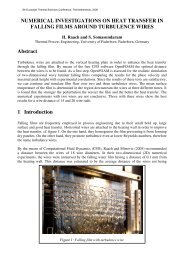
Figure 1: Design of the experimental test section.<br />
In order to investigate heat transfer and fluid flow within a single minichannel a unique measuring<br />
test section has been designed (Figure 1) and built. Either single-phase tests or experiments during<br />
forced convective condensation and flow boiling phenomenon can be studied with the present<br />
facility. The test section is made of a straight single minichannel with two diabatic and two<br />
adiabatic sectors along its length (Figure 2). The diabatic sectors work as heat exchangers with an<br />
adoption of a secondary fluid; hence experiments are referred to a constant wall temperature<br />
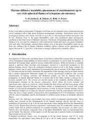
boundary condition. The two sectors are made from 8 mm external diameter cupper bar with 0.96<br />
mm internal bore which is the minichannel itself. The thick-walled tube was machined externally so<br />
as to obtain cooling water channel within the wall thickness. The tortuous path for the secondary<br />
fluid enables a good water mixing properties and thus allows precise local coolant temperature<br />
measurements. In this test section, 15 thermocouples have been inserted into the water channel<br />
along the MS in order to measure the coolant temperature profile. The enhanced coolant heat<br />
transfer surface area moves the thermal resistance toward the internal side and thus reduces the<br />
experimental heat transfer coefficient error due to the refrigerant to wall temperature difference.<br />
In order to measure precise local HTC values 15 thermocouples have been inserted into the wall<br />
thickness, near the minichannel along the measuring sector, without making thermocouple wires<br />
cross the coolant path. Furthermore, two thermocouples and a thermopile are measuring the<br />
refrigerant temperature by measuring external wall surface temperature of the adiabatic sectors –<br />
stainless steel capillary tubes at the two extremes of the measuring sector. When operating in<br />
condensation mode, the first diabatic sector works as a desuperheater. To avoid big temperature<br />
gradients at the inlet of the measuring sector the desuperheater is used to cool down the superheated<br />
refrigerant to the saturation state at the inlet of the measuring sector. Vapor quality is there obtained<br />
from the thermal balance on the coolant side, whereas saturation conditions are checked using the<br />
adiabatic wall temperature and the pressure measurement in the adiabatic sectors.<br />
Thermocouples, thermopile and pressure ports<br />
for fluid temperature and pressure recording<br />
Figure 2: The test section.<br />
30 thermocouples for wall and coolant<br />
temperature measurements
5th European Thermal-Sciences Conference, The Netherlands, <strong>2008</strong><br />
3 The Experimental Technique<br />
3.1 Theory<br />
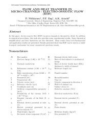
Condensation heat transfer is performed in the second diabatic sector. It is equipped with 15<br />
thermocouples set in the water channel along the sector, hence the coolant temperature profile is<br />
obtained (Figure 3). The derivative of the temperature profile is proportional to the local heat flux:<br />
1 d Tc<br />
( z)<br />
q'( z)<br />
= m ⋅ c<br />
cpw<br />
π d<br />
⋅ , [W m -2 ] (1)<br />
⋅ dz<br />
i<br />
and it is associated to the local heat transfer coefficient:<br />
HTC ( z)<br />
=<br />
i<br />
q'( z)<br />
( T ( z) −T ( z)<br />
)<br />
sat<br />
w<br />
. [W m -2 K -1 ] (2)<br />
Local saturation temperature (T sat (z)) of the fluid along the sector is calculated from the two<br />
measured values in the adiabatic sectors. The calculation, which considers frictional pressure drop<br />
and pressure recovery due to condensation, is iterative. It is modified so as to take into account local<br />
pressure gradient profile and make the saturation temperature curve converge with the saturation<br />
temperature measurement at the outlet of the measuring sector. On the other hand, the wall<br />
temperature (T wall (z)) is measured locally.<br />
Considering the conservation of energy in the sector, the coolant temperature change is directly<br />
associated to the corresponding enthalpy variation of the refrigerant. Therefore, the local vapor<br />
quality is calculated as follows:<br />
xz ( ) = x −<br />
in<br />
z<br />
π ⋅d ⋅ q'( z)dz<br />
i<br />
m<br />
r<br />
∫<br />
0<br />
⋅h<br />
LG<br />
. [ / ] (3)<br />
45<br />
dT w ( z)<br />
dz<br />
40<br />
T [°C]<br />
35<br />
30<br />
T ( z) −T ( z)<br />
sat<br />
wall<br />
Sat (TC)<br />
Sat (PT)<br />
Wall<br />
Water<br />
TC+TP<br />
TC inox<br />
25<br />
20<br />
z<br />
0 40 80 120 160 200 240<br />
Axial position [mm]<br />
Figure 3: Temperature measurements within the single minichannel test section.
5th European Thermal-Sciences Conference, The Netherlands, <strong>2008</strong><br />
3.2 Improvement of the Measuring Technique<br />
With the purpose of optimum performance of the setup, different experimental uncertainty issues<br />
were studied. It has been shown that there are certain test conditions, which result in the minimum<br />
nominal error for each relative measurement (Cavallini et al., 2005b). Nevertheless, the effects of<br />
heat dissipation, ambient and coolant temperature, viscous heating, wall temperature measurement,<br />
axial heat conduction and coolant mass flow rate were all taken into consideration in the final data<br />
reduction (Matkovič, 2006). Furthermore, precise calibration of the test apparatus has been<br />
performed regularly to maintain the reliability of performed measurements.<br />
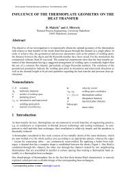
As an example of the technique enhancement, the influence of the heat dissipation rate on vapor<br />
quality change is here illustrated. Hereby, the heat exchange in the two sectors was measured at<br />
different boundary conditions. Moreover, coolant to ambient temperature difference was varied<br />
systematically while there was no refrigerant flow in the sectors. In this way the measured heat gain<br />
or heat loss in a wide range of test conditions was used to correct the total heat flow rate. Heat<br />
dissipation in the first heat exchanger results in inlet vapor quality change (Figure 4), whereas<br />
accounting for the heat dissipation in the measuring sector is somewhat more complicated. There<br />
are two major issues for heat dissipation in the sector. The first one refers to a local heat dissipation<br />
rate which directly affects the local measurement of the refrigerant heat flux and hence the local<br />
heat transfer coefficient. In this context, the local specific heat dissipation rate q<br />
diss<br />
was calculated<br />
from the overall measured heat loss in the MS ( Q <br />
MSdiss<br />
), the local and the integral value of coolant<br />
minus ambient temperature difference along the sector (Equation 4).<br />
Q<br />
MSdiss<br />
q diss<br />
( z) = ⋅[ Tc ( z)<br />
−T<br />
Z<br />
amb ]<br />
[W m -2 ] (4)<br />
π ⋅d ⋅ T z −T ⋅dz<br />
∫[ ( ) ]<br />
i c amb<br />
0<br />
The second one, instead, refers to the cumulative value of the heat dissipation rate along the MS,<br />
which leads to the required correction for the local vapor quality calculation (Figure 4). Similarly,<br />
all the other different effects mentioned above have been studied with the motivation of<br />
experimental precision enhancement.<br />
1,5<br />
1,5<br />
Dissipated Heat Flow Rate [W]<br />
1,0<br />
0,5<br />
0,0<br />
-0,5<br />
-1,0<br />
-1,5<br />
Pre-sector<br />
Measuring sector<br />
-10 -5 0 5 10<br />
Water to Ambient Temperature Difference [°C]<br />
Dissipated Heat Flow Rate [ W ]<br />
1,0<br />
0,5<br />
0,0<br />
-0,5<br />
G100<br />
G200<br />
G400<br />
-1,0<br />
G600<br />
G1000<br />
G1600<br />
-1,5<br />
-0,10 -0,05 0,00 0,05 0,10<br />
dx [ / ]<br />
Figure 4: (left) Heat dissipation measurement for the two sectors versus water to ambient temperature<br />
difference. Tests were performed at water mass flow rates around 10 kg/h; (right) Calculated effect of the<br />
dissipated heat on vapor quality change for different mass velocities of R32.
5th European Thermal-Sciences Conference, The Netherlands, <strong>2008</strong><br />
3.3 Experimental Uncertainty<br />
Nominal uncertainty of the local heat transfer coefficient during condensation of R32 within a<br />
single minichannel test tube has been calculated from equation 5. The first term is associated to the<br />
coolant mass flow rate uncertainty; the second term refers to the coolant temperature gradient; the<br />
third one to the saturation to wall temperature difference and the last one to the uncertainty of the<br />
internal diameter dimension. Nominal error for the coolant temperature gradient was assumed to be<br />
equal to 0.2 K over the length of the measuring sector, 0.15 K for the saturation to the wall<br />
temperature difference and 0.02 mm for the minichannel diameter. On the other hand, the coolant<br />
mass flow meter nominal error was defined from the calibration curve given by manufacturer.<br />
2 2 2 2<br />
⎛ ∂HTC(z) ⎞ ⎛ ∂HTC(z) ⎞ ⎛ ∂HTC(z) ⎞ ⎛ ∂HTC(z)<br />
⎞<br />
δ<br />
HTC(z)<br />
= ⎜ ⋅δ<br />
m<br />
( m<br />
)<br />
c c ⎟ + ⎜ ⋅δ<br />
Tc′ ⎟ + ⎜ ⋅δ<br />
ΔTr−<br />
w<br />
⎟ + ⎜ ⋅δdh<br />
⎟<br />
⎝ ∂m<br />
c ⎠ ⎝ ∂T ′<br />
c(z) ⎠ ⎝ ∂ΔT r−<br />
w(z) ⎠ ⎝ ∂dh<br />
⎠<br />
(5)<br />
Bars of the experimental uncertainty calculated from the equation above are plotted in Figure 7 for<br />
all referenced heat transfer coefficients.<br />
4 Experimental Results<br />
The local heat transfer coefficient has been measured during condensation of the high pressure<br />
refrigerant R32 inside a horizontal single circular 0.96 mm diameter minichannel. The experiments<br />
have been performed over the entire range of vapor quality at 40°C saturation temperature and mass<br />
velocity ranging from 100 kg m -2 s -1 up to 1200 kg m -2 s -1 . In the present technique, the dominant<br />
thermal resistance during the condensing process is on the refrigerant side, as can be seen from<br />
Figure 3. This is favorable to the reduction of the experimental uncertainty associated to the<br />
determination of the heat transfer coefficient. Since the purpose of the present apparatus is to<br />
accurately measure the local heat transfer coefficient, several tests have been performed to verify<br />
that the heat transfer coefficient does not depend on the conditions of the secondary fluid.<br />
Besides, Figure 5 shows the experimental heat transfer coefficient measured at 600 kg m -2 s -1 by<br />
imposing different inlet conditions to the refrigerant entering the test section. In the test runs, the<br />
refrigerant has been first sent as superheated vapor to the measuring sector, and then at lower and<br />
HTC [kW m -2 K -1 ]<br />
25<br />
20<br />
15<br />
10<br />
G600 sup.<br />
G600 x=0.95<br />
G600 x=0.95r<br />
G600 x=0.91<br />
G600 x=0.87<br />
G600 x=0.82<br />
G600 x=0.78<br />
HTC [kW m -2 K -1 ]<br />
10<br />
8<br />
6<br />
4<br />
G200 t=19°C<br />
G200 t=22°C<br />
G200 t=25°C<br />
G200 t=26°C<br />
G200 t=29°C<br />
5<br />
2<br />
0<br />
0,0 0,1 0,2 0,3 0,4 0,5 0,6 0,7 0,8 0,9 1,0<br />
VAPOUR QUALITY [/]<br />
Figure 5: Experimental local heat transfer coefficient<br />
versus vapour quality at different inlet vapour<br />
conditions ranging from superheating to 0.78 quality.<br />
0<br />
0,0 0,1 0,2 0,3 0,4 0,5 0,6 0,7 0,8 0,9 1,0<br />
VAPOUR QUALITY [/]<br />
Figure 6: Experimental local heat transfer coefficient<br />
versus vapour quality at different inlet inlet coolant<br />
temperatures ranging from 19 °C to 29 °C.
5th European Thermal-Sciences Conference, The Netherlands, <strong>2008</strong><br />
HTC [kW m -2 K -1 ]<br />
26<br />
24<br />
22<br />
20<br />
18<br />
16<br />
14<br />
12<br />
10<br />
8<br />
G1200<br />
G1000<br />
G800<br />
G600<br />
G400<br />
G200<br />
G100<br />
6<br />
4<br />
2<br />
0<br />
0,0 0,1 0,2 0,3 0,4 0,5 0,6 0,7 0,8 0,9 1,0<br />
x [ / ]<br />
Figure 7: Experimental local heat transfer coefficient during condensation of R32 inside single minichannel<br />
versus vapour quality at different mass velocities ranging from 100 kg m -2 s -1 to 1200 kg m -2 s -1 .<br />
lower values of vapor quality, down to 78% quality. The local heat transfer coefficient determined<br />
in the different test runs perfectly overlap, as it can be seen in Figure 5. That is, the present test<br />
apparatus provides exactly the same value of the heat transfer coefficient at the same refrigerant<br />
conditions, no matter which location this coefficient is measured along the channel. Beside mass<br />
velocity and vapor quality, the effect of the saturation to wall temperature difference can be<br />
investigated by varying the inlet temperature of the coolant. Such a study has been conducted at 200<br />
kg m -2 s -1 with coolant temperature ranging between 19 and 29 °C, at constant refrigerant saturation<br />
temperature. Because of the peculiar design of the coolant channel, as previously mentioned, the<br />
dominant thermal resistance is on the refrigerant side and therefore these variations of the coolant<br />
temperature imply a consequent significant change in the wall temperature and thus in the saturation<br />
to wall temperature difference. The results are plotted in Figure 6, showing no effect of the<br />
temperature difference in the heat transfer coefficient at 200 kg m -2 s -1 . These results confirm that<br />
the effect of gravity in around 1 mm diameter channel is not significant in comparison with the<br />
other forces influencing the condensation heat transfer at 200 kg m -2 s -1 mass velocity.<br />
The complete set of the experimental heat transfer coefficients is plotted in Figure 7 versus vapor<br />
quality. As expected for forced convective condensation inside conventional pipes, the experimental<br />
heat transfer coefficients measured at 100 kg m -2 s -1 and those at 200 kg m -2 s -1 are very close to each<br />
other, showing little effect of mass velocity. It is worth reminding that the lower the mass velocity<br />
the higher the experimental uncertainty of the heat transfer coefficient, due to the low local heat<br />
fluxes. Nevertheless, this overlapping of the HTCs at the lower tested values of mass velocity was<br />
not found with the refrigerant R134a and may be explained with the flow pattern and the properties<br />
of R32.<br />
4.1 Comparison against Models<br />
Experimental results have been compared against six different models available in the open<br />
literature. Akers et al. (1959), Cavallini et al. (2002) and Cavallini et al. (2006) were all developed<br />
for HTC predictions inside macro-scale tubes. Moreover, Wang et al. (2002), Cavallini et al.<br />
(2005a) and Moser et al. (1998) are here adopted. The model by Moser et al. (1998) was initially<br />
developed for conventional pipes and later on modified by using the Zhang and Webb (2001) for<br />
pressure drop calculation inside small-diameter tubes. The model by Cavallini et al. (2005a) has<br />
been built on a database of HTC measurements for three different fluids during condensation inside<br />
multi-port extruded aluminium tube with smooth square minichannels. The graphs show the good
5th European Thermal-Sciences Conference, The Netherlands, <strong>2008</strong><br />
Figure 8: Comparison of the experimental heat transfer coefficients versus prediction models. Akers et al.<br />
(1959), Cavallini et al. (2002) and Cavallini et al. (2006) were developed for macro scale tubes, whereas<br />
Moser et al. (1998) modified by Zhang and Webb (2001), Wang et al. (2002) and Cavallini et al. (2005a)<br />
are used for HTC prediction during condensation inside minichannels.
5th European Thermal-Sciences Conference, The Netherlands, <strong>2008</strong><br />
performance of models developed for macro-scale condensation such as the ones by Cavallini et al.<br />
(2002, 2006). Good agreement with experimental data is also shown by Moser et al. (1998) (Figure<br />
8). None of the correlations is able to satisfactory predict the heat transfer coefficient measurements<br />
taken at 100 kg m -2 s -1 . Akers et al. (1959) and Wang et al. (2002) systematically under predict heat<br />
transfer coefficients whereas Cavallini et al. (2005a) model overestimates HTCs. Similar agreement<br />
between macro-scale models and experimental results was also found with the lower pressure<br />
refrigerant R134a (Cavallini et al. 2007).<br />
5 Concluding Remarks<br />
Heat transfer coefficients during condensation of R32 inside a horizontal circular single<br />
minichannel have been measured for a wide range of test conditions. The high pressure fluid has<br />
been tested at 40 °C saturation temperature over the entire span of vapor qualities and mass<br />
velocities ranging from 100 to 1200 kg m -2 s -1 . HTCs have been obtained from just above 1000 W<br />
m -2 K -1 to 24 kW m -2 K -1 . The novel test facility and the experimental technique have been shown to<br />
work efficiently in a wide range of test conditions. Improvement of the measuring technique prior to<br />
the test runs as well as validation of measurements in post processing have turned out to be crucial<br />
for the assessment of precise heat transfer coefficients. Finally, overall good predictive capability of<br />
applied correlations over the entire range of test conditions, but the lowest mass velocity, has been<br />
shown in the paper. Macro-scale models for condensation heat transfer coefficient have been found<br />
efficient in HTC prediction during condensation of R32 inside minichannels.<br />
6 References<br />
Akers, W.W., Deans, H.A., Crosser, O.K., 1959, Condensing heat transfer within horizontal tubes,<br />
Chem. Eng.Prog. Symp. Series, vol. 55, pp. 171-176.<br />
Cavallini A., Del Col D., Doretti L., Matkovic M., Rossetto L., Zilio C., 2005a, A model for<br />
condensation inside minichannels. HT05 National Heat Transfer Conference. July 17-22, San<br />
Francisco, CA, USA. Paper No. HT2005-72528.<br />
Cavallini A., Del Col D., Matkovic M., Rossetto L., 2005b, Measurement of the heat transfer<br />
coefficient during condensation in a circular minichannel. IIR International Conference<br />
Thermophysical Properties and Transfer Processes of Refrigerants. 31 Aug-2 Sept, Vicenza, Italy.<br />
pp. 103-110, ISSN 0151-1637, ISBN 2-913149-43-X.<br />
Cavallini A., Censi G., Del Col D., Doretti L., Matkovic M., Rossetto L. and Zilio C., 2006,<br />
Condensation in Horizontal Smooth Tubes: A New Heat Transfer Model for Heat Exchanger<br />
Design. Heat Transfer Engineering. Vol. 27 no.8, pp. 31-38, ISSN: 0145-7632.<br />
Cavallini A., Del Col D., Matkovic M., Rossetto L., 2007, Local Heat Transfer Coefficient During<br />
Condensation inside a Single Minichannel, Sixth International Conference on Enhanced, Compact<br />
and Ultra-Compact Heat Exchangers: Science, Engineering and Technology, September 16-21,<br />
Potsdam, Germany.<br />
Matkovič M., 2006, Experimental Condensation inside Minichannels, Ph.D. Thesis, Università di<br />
<strong>Padova</strong>, 209 p.<br />
Moser K. W., Webb R. L., Na B., 1998, A new equivalent Reynolds number model for<br />
condensation in smooth tubes, J. of Heat Transfer, 120: 410-417.<br />
Wang Wei-Wen W., Radcliff T.D., Christensen R.N., 2002, A condensation heat transfer<br />
correlation for millimetre-scale tubing with flow regime transition, Experimental Thermal and Fluid<br />
Science, vol. 26, pp. 473-485.<br />
Zhang M., Webb R.L., 2001, Correlation of two-phase friction for refrigerants in small-diameter<br />
tubes, Experimental Thermal and Fluid Science, vol. 25, pp. 131-139.