99-7401 AW-709NI DW-7401 INSTALLATION - Installer.com
99-7401 AW-709NI DW-7401 INSTALLATION - Installer.com
99-7401 AW-709NI DW-7401 INSTALLATION - Installer.com

Create successful ePaper yourself
Turn your PDF publications into a flip-book with our unique Google optimized e-Paper software.
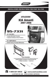
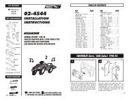
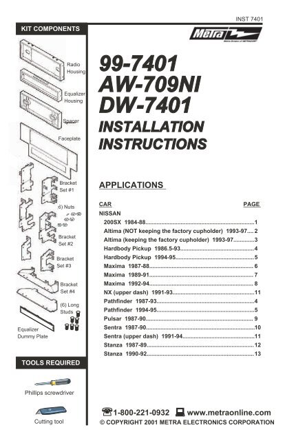
KIT COMPONENTS<br />
INST <strong>7401</strong><br />
Radio<br />
Housing<br />
Equalizer<br />
Housing<br />
Spacer<br />
Faceplate<br />
<strong>99</strong>-<strong>7401</strong><br />
<strong>AW</strong>-<strong>709NI</strong><br />
<strong>DW</strong>-<strong>7401</strong><br />
<strong>INSTALLATION</strong>TION<br />
INSTRUCTIONS<br />
Equalizer<br />
Dummy Plate<br />
Bracket<br />
Set #1<br />
(6) Nuts<br />
Bracket<br />
Set #2<br />
Bracket<br />
Set #3<br />
Bracket<br />
Set #4<br />
(6) Long<br />
Studs<br />
TOOLS REQUIRED<br />
APPLICATIONS<br />
CAR PAGE<br />
NISSAN<br />
200SX 1984-88....................................................................1<br />
Altima (NOT keeping the factory cupholder) 1<strong>99</strong>3-97.... 2<br />
Altima (keeping the factory cupholder) 1<strong>99</strong>3-97.............3<br />
Hardbody Pickup 1986.5-93..............................................4<br />
Hardbody Pickup 1<strong>99</strong>4-95.................................................5<br />
Maxima 1987-88................................................................. 6<br />
Maxima 1989-91................................................................. 7<br />
Maxima 1<strong>99</strong>2-94................................................................. 8<br />
NX (upper dash) 1<strong>99</strong>1-93...................................................11<br />
Pathfinder 1987-93.............................................................4<br />
Pathfinder 1<strong>99</strong>4-95.............................................................5<br />
Pulsar 1987-90................................................................... 9<br />
Sentra 1987-90....................................................................10<br />
Sentra (upper dash) 1<strong>99</strong>1-94.............................................11<br />
Stanza 1987-89...................................................................12<br />
Stanza 1<strong>99</strong>0-92...................................................................13<br />
Phillips screwdriver<br />
Cutting tool<br />
1-800-221-0932 www.metraonline.<strong>com</strong><br />
© COPYRIGHT 2001 METRA ELECTRONICS CORPORATION
NISSAN 200SX 1984-88<br />
1<br />
2<br />
Disconnect the negative battery terminal to<br />
prevent an accidental short circuit. Remove<br />
(1) #10 Phillips screws from each side of the<br />
center console. Unsnap the coin tray and<br />
remove (2) #10 Phillips screws exposed. Lift<br />
the storage box carpet out and remove (2)<br />
#10 Phillips screws exposed. Remove the<br />
ashtray and (2) #8 Phillips screws exposed.<br />
Remove the dash trim bezel. Remove (4)<br />
screws securing the factory head unit and<br />
disconnect the wiring.<br />
Using the scored lines as a guide, cut and<br />
remove the dashed portions of the<br />
Faceplate.<br />
3<br />
4<br />
"B"<br />
"B"<br />
"B"<br />
"B"<br />
Snap the converted Faceplate onto the front of<br />
the Radio Housing.<br />
Cut and remove all mounting tabs on<br />
Bracket Set #4 EXCEPT tabs "B". The<br />
mounting tabs can be identified by the<br />
stamped letter on the back of each tab.<br />
Skip to the Installation Instructions for<br />
ALL VEHICLES on Page #14.<br />
1
NISSAN Altima 1<strong>99</strong>3-97<br />
(IF KEEPING THE FACTORY CUPHOLDER IS NOT DESIRED)<br />
1<br />
2<br />
Disconnect the negative battery terminal to<br />
prevent an accidental short circuit. Remove<br />
the gear shifter cover and (4) Phillips screws<br />
exposed. Remove (2) Phillips screws from<br />
the driver's side knee bolster and lower the<br />
panel. Remove (1) screw exposed on the<br />
left corner of the dash trim bezel. Remove<br />
(2) screws above the radio opening and<br />
gently unclip the bezel. Remove (4) screws<br />
securing the factory head unit and<br />
disconnect the wiring.<br />
3<br />
Using the scored lines as a guide, cut and<br />
remove the dashed portions of the<br />
Faceplate.<br />
4<br />
"F"<br />
Slide the Equalizer Housing onto the bottom<br />
of the Radio Housing and snap the<br />
converted Faceplate onto the front of the<br />
Housing.<br />
Cut and remove all mounting tabs on<br />
Bracket Set #2 EXCEPT tabs "F". The<br />
mounting tabs can be identified by the<br />
stamped letter on the back of each tab.<br />
Skip to the Installation Instructions for ALL<br />
VEHICLES on Page #14.<br />
2
NISSAN Altima 1<strong>99</strong>3-97<br />
(IF KEEPING THE FACTORY CUPHOLDER IS DESIRED)<br />
1<br />
2<br />
Disconnect the negative battery terminal to<br />
prevent an accidental short circuit. Remove<br />
the gear shifter cover and (4) Phillips screws<br />
exposed. Remove (2) Phillips screws from<br />
the driver's side knee bolster and lower the<br />
panel. Remove (1) screw exposed on the<br />
left corner of the dash trim bezel. Remove<br />
(2) screws above the radio opening and<br />
gently unclip the bezel. Remove (4) screws<br />
securing the factory head unit and<br />
disconnect the wiring.<br />
3<br />
Using the scored lines as a guide, cut and<br />
remove the dashed portions of the<br />
Faceplate.<br />
4<br />
"F"<br />
FACTORY<br />
CUPHOLDER<br />
MOUNTING<br />
POSITIONS<br />
3<br />
Snap the converted Faceplate onto the front<br />
of the Housing.<br />
Cut and remove all mounting tabs on<br />
Bracket Set #2 EXCEPT tabs "F". The<br />
mounting tabs can be identified by the<br />
stamped letter on the back of each tab.<br />
Mount the cupholder to the Brackets during<br />
the kit assembly in step #5 using the<br />
mounting positions indicated above. Skip<br />
to the Installation Instructions for ALL<br />
VEHICLES on Page #14.
NISSAN Hardbody Pickup / Pathfinder 1986-85<br />
1<br />
2<br />
Disconnect the negative battery terminal to<br />
prevent an accidental short circuit. Remove<br />
the ashtray and (1) screw exposed in the<br />
top-right corner. Remove (2) Phillips screws<br />
above the climate controls. Remove (2)<br />
Phillips screws from the bottom of the dash<br />
trim bezel. Unsnap the bezel and<br />
disconnect the cigarette lighter wiring.<br />
Remove (4) screws securing the factory<br />
head unit and disconnect the wiring.<br />
Using the scored lines as a guide, cut and<br />
remove the dashed portions of the<br />
Faceplate.<br />
3<br />
4<br />
"A"<br />
"A"<br />
"A"<br />
"A"<br />
Snap the converted Faceplate onto the front of<br />
the Radio Housing.<br />
Cut and remove all mounting tabs on<br />
Bracket Set #4 EXCEPT tabs "A". The<br />
mounting tabs can be identified by the<br />
stamped letter on the back of each tab.<br />
Skip to the Installation Instructions for<br />
ALL VEHICLES on Page #14.<br />
4
NISSAN Hardbody Pickup / Pathfinder 1<strong>99</strong>4-97<br />
1<br />
2<br />
Disconnect the negative battery terminal to<br />
prevent an accidental short circuit. Remove<br />
(2) screws above the radio opening.<br />
Remove the ashtray. Unclip the dash trim<br />
bezel and remove. Remove (4) screws<br />
securing the factory head unit and<br />
disconnect the wiring.<br />
Using the scored lines as a guide, cut and<br />
remove the dashed portions of the<br />
Faceplate.<br />
3<br />
4<br />
"H"<br />
5<br />
Slide the Equalizer Housing onto the bottom of<br />
the Radio Housing and snap the converted<br />
Faceplate onto the front of the Housing.<br />
Cut and remove all mounting tabs on<br />
Bracket Set #1 EXCEPT tabs "H". The<br />
mounting tabs can be identified by the<br />
stamped letter on the back of each tab.<br />
Skip to the Installation Instructions for<br />
ALL VEHICLES on Page #14.
NISSAN Maxima 1987-88<br />
1<br />
2<br />
Disconnect the negative battery terminal to<br />
prevent an accidental short circuit. Remove<br />
(2) Phillips screws from the bottom of the<br />
dash trim bezel. Remove (2) Phillips screws<br />
above the radio opening. Unsnap the dash<br />
trim bezel and disconnect the defroster and<br />
rear wiper wiring. Remove (4) screws<br />
securing the factory head unit and<br />
disconnect the wiring.<br />
Using the scored lines as a guide, cut and<br />
remove the dashed portions of the<br />
Faceplate.<br />
3<br />
4<br />
"B"<br />
Slide the Equalizer Housing onto the bottom of<br />
the Radio Housing and snap the converted<br />
Faceplate onto the front of the Housing.<br />
Cut and remove all mounting tabs on<br />
Bracket Set #2 EXCEPT tabs "B". The<br />
mounting tabs can be identified by the<br />
stamped letter on the back of each tab.<br />
Skip to the Installation Instructions for<br />
ALL VEHICLES on Page #14.<br />
6
NISSAN Maxima 1989-91<br />
1<br />
2<br />
Disconnect the negative battery terminal to<br />
prevent an accidental short circuit. Remove<br />
(2) Phillips screws above the radio opening.<br />
Remove the ashtray and (1) screw in the<br />
right corner of the ashtray housing. Remove<br />
(1) screw below the cigarette lighter and<br />
unclip the dash trim bezel. Remove (4)<br />
screws securing the factory head unit and<br />
disconnect the wiring.<br />
Using the scored lines as a guide, cut and<br />
remove the dashed portions of the<br />
Faceplate.<br />
3<br />
4<br />
"E"<br />
"E"<br />
"E"<br />
"E"<br />
Slide the Equalizer Housing onto the bottom of<br />
the Radio Housing and snap the converted<br />
Faceplate onto the front of the Housing.<br />
7<br />
Cut and remove all mounting tabs on<br />
Bracket Set #1 EXCEPT tabs "E". The<br />
mounting tabs can be identified by the<br />
stamped letter on the back of each tab.<br />
Skip to the Installation Instructions for<br />
ALL VEHICLES on Page #14.
NISSAN Maxima 1<strong>99</strong>2-94<br />
1<br />
2<br />
Disconnect the negative battery terminal to<br />
prevent an accidental short circuit. Pry up<br />
on the gear shifter trim panel and remove.<br />
Remove the ashtray and (1) screw exposed<br />
in the right corner of the ashtray housing. If<br />
equipped with an automatic transmission<br />
power/<strong>com</strong>fort switch: unsnap the switch<br />
from the dash trim bezel. Unclip the bezel.<br />
Disconnect the cigarette lighter and flasher<br />
wiring. Remove (4) screws securing the<br />
factory head unit and disconnect the wiring.<br />
Using the scored lines as a guide, cut and<br />
remove the dashed portions of the<br />
Faceplate.<br />
3<br />
4<br />
"G"<br />
"G"<br />
"G"<br />
"G"<br />
Slide the Equalizer Housing onto the bottom of<br />
the Radio Housing and snap the converted<br />
Faceplate onto the front of the Housing.<br />
Cut and remove all mounting tabs on<br />
Bracket Set #2 EXCEPT tabs "G". The<br />
mounting tabs can be identified by the<br />
stamped letter on the back of each tab.<br />
Skip to the Installation Instructions for<br />
ALL VEHICLES on Page #14.<br />
8
NISSAN Pulsar 1987-90<br />
1<br />
2<br />
Disconnect the negative battery terminal to<br />
prevent an accidental short circuit. Remove<br />
(3) screws above the climate controls and<br />
(2) screws from the bottom edge of the dash<br />
trim bezel. Unclip the bezel and remove.<br />
Remove (4) screws from the factory head<br />
unit and disconnect the wiring.<br />
Using the scored lines as a guide, cut and<br />
remove the dashed portions of the<br />
Faceplate.<br />
3<br />
4 "D"<br />
"D"<br />
"D"<br />
Slide the Equalizer Housing onto the bottom of<br />
the Radio Housing and snap the converted<br />
Faceplate onto the front of the Housing.<br />
9<br />
Cut and remove all mounting tabs on<br />
Bracket Set #1 EXCEPT tabs "D". The<br />
mounting tabs can be identified by the<br />
stamped letter on the back of each tab.<br />
Skip to the Installation Instructions for<br />
ALL VEHICLES on Page #14.
NISSAN Sentra 1987-90<br />
1<br />
2<br />
Disconnect the negative battery terminal to<br />
prevent an accidental short circuit. Remove<br />
the ashtray. Remove (2) screws above the<br />
climate controls. Remove (2) screws from<br />
the base of the dash trim bezel and remove<br />
the bezel. Remove the screws securing the<br />
factory head unit and disconnect the wiring.<br />
Using the scored lines as a guide, cut and<br />
remove the dashed portions of the<br />
Faceplate.<br />
3<br />
4<br />
"A"<br />
"A"<br />
"A"<br />
Snap the converted Faceplate onto the front of<br />
the Radio Housing.<br />
"A"<br />
Cut and remove all mounting tabs on<br />
Bracket Set #3 EXCEPT tabs "A". The<br />
mounting tabs can be identified by the<br />
stamped letter on the back of each tab.<br />
Skip to the Installation Instructions for<br />
ALL VEHICLES on Page #14.<br />
10
NISSAN Sentra (upper dash) 1<strong>99</strong>1-94<br />
NX (upper dash) 1<strong>99</strong>1-93<br />
1<br />
2<br />
Disconnect the negative battery terminal to<br />
prevent an accidental short circuit. Remove<br />
the ashtray and (2) screws exposed in the<br />
ashtray cavity. Remove (2) screws above<br />
the radio opening. Pull the a/c vents out and<br />
remove (1) screw behind each one. (The left<br />
vent secures the vent control cable). Unclip<br />
the dash trim bezel. Disconnect the<br />
cigarette lighter, illumination and switch<br />
wiring.<br />
Using the scored lines as a guide, cut and<br />
remove the dashed portions of the<br />
Faceplate.<br />
3<br />
4<br />
"B"<br />
"B"<br />
"B"<br />
"B"<br />
11<br />
Slide the Equalizer Housing onto the bottom of<br />
the Radio Housing and snap the converted<br />
Faceplate onto the front of the Housing.<br />
Cut and remove all mounting tabs on<br />
Bracket Set #3 EXCEPT tabs "B". The<br />
mounting tabs can be identified by the<br />
stamped letter on the back of each tab.<br />
Skip to the Installation Instructions for<br />
ALL VEHICLES on Page #14.
NISSAN Stanza 1987-89<br />
1<br />
2<br />
Disconnect the negative battery terminal to<br />
prevent an accidental short circuit. Remove<br />
the ashtray and (2) screws exposed at the<br />
base of the dash trim bezel. Remove (2)<br />
screws above the climate controls and<br />
unclip the bezel. Remove (4) screws<br />
securing the factory head unit and<br />
disconnect the wiring.<br />
Using the scored lines as a guide, cut and<br />
remove the dashed portions of the<br />
Faceplate.<br />
3<br />
4<br />
"A"<br />
"A"<br />
"A"<br />
"A"<br />
Slide the Equalizer Housing onto the bottom of<br />
the Radio Housing and snap the converted<br />
Faceplate onto the front of the Housing.<br />
Cut and remove all mounting tabs on<br />
Bracket Set #2 EXCEPT tabs "A". The<br />
mounting tabs can be identified by the<br />
stamped letter on the back of each tab.<br />
Skip to the Installation Instructions for<br />
ALL VEHICLES on Page #14.<br />
12
NISSAN Stanza 1<strong>99</strong>0-92<br />
1<br />
2<br />
Disconnect the negative battery terminal to<br />
prevent an accidental short circuit. Remove<br />
the ashtray and (2) screws exposed in the<br />
ashtray cavity. Remove (2) screws above<br />
the radio opening. Remove (2) screws from<br />
the left side of the steering column and (1)<br />
screw from the right side. Unclip the dash<br />
trim bezel. Disconnect the flasher, rear<br />
defroster and headlight wiring.<br />
Using the scored lines as a guide, cut and<br />
remove the dashed portions of the<br />
Faceplate.<br />
3<br />
4<br />
"C"<br />
"C"<br />
"C"<br />
"C"<br />
13<br />
Slide the Equalizer Housing onto the bottom of<br />
the Radio Housing and snap the converted<br />
Faceplate onto the front of the Housing.<br />
Cut and remove all mounting tabs on<br />
Bracket Set #1 EXCEPT tabs "C". The<br />
mounting tabs can be identified by the<br />
stamped letter on the back of each tab.<br />
Skip to the Installation Instructions for<br />
ALL VEHICLES on Page #14.
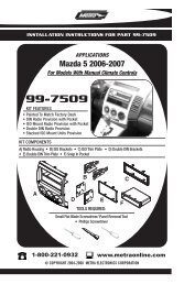
5<br />
ALL VEHICLES<br />
Fig. A<br />
Fig. C<br />
Fig. B<br />
Fig. D<br />
Fig. E<br />
HARDBODY 1<strong>99</strong>4-95, PA THFINDER 1<strong>99</strong>4-95, ALTIMA (no cupholder), MAXIMA,<br />
PULSAR, STANZA: Slide the Brackets into the Radio Housing (along the inner walls) and<br />
mount to the Housing with (6) Long Studs and (6) Nuts. (see Fig. A)<br />
ALTIMA (cupholder): Slide the Brackets into the Radio Housing (along the inner walls).<br />
Mount the Brackets to the Housing with (4) Long Studs and (4) Nuts. Mount the cupholder to<br />
the Brackets with (4) screws previously removed from the factory assembly. (see Fig. B)<br />
NX, SENTRA: Slide the Brackets into the Radio Housing (along the inner walls) and mount to<br />
the Housing with (4) Long Studs and (4) Nuts. (see Fig. C)<br />
200SX: Slide the Brackets into the Radio Housing (along the inner walls) and mount through<br />
the outer holes of the Housing with (4) Long Studs and (4) Nuts. (see Fig. D)<br />
HARDBODY 1987-93, PA THFINDER 1987-93: Slide the Brackets into the Radio Housing<br />
(along the inner walls) and mount through the inner holes of the Housing with (4) Long Studs<br />
and (4) Nuts. (see Fig. E)<br />
14
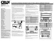
6<br />
Fig. A<br />
*OPTIONAL<br />
*OPTIONAL<br />
Fig. B<br />
2-SHAFT HEAD UNITS: Attach the Spacer* to the Radio Housing. Slide the aftermarket<br />
head unit into the kit and secure with shaft nuts. (see Fig. A)<br />
DIN HEAD UNITS: Cut and remove the shaft supports from the Spacer* and Radio Housing.<br />
Slide the DIN cage into the Radio Housing and secure by bending the metal locking tabs<br />
down. Slide the aftermarket head unit into the cage until secure. (see Fig. B)<br />
(If an equalizer will be included, slide the unit into the back of the Radio Housing and secure.<br />
If an equalizer will NOT be included, snap the Equalizer Dummy Plate into the opening).<br />
7 8<br />
A<br />
B<br />
C<br />
D<br />
A) Strip wire ends back ½"<br />
B) Twist ends together<br />
C) Solder<br />
D) Tape<br />
Locate the factory wiring harness in the<br />
dash. Metra re<strong>com</strong>mends using the<br />
proper mating adaptor and making<br />
connections as shown. (Isolate and<br />
individually tape off the ends of any<br />
unused wires to prevent electrical short<br />
circuit).<br />
Re-connect the battery terminal and test the unit<br />
for proper operation. Mount the head unit/kit<br />
assembly to the sub-dash with those screws<br />
previously removed.<br />
15<br />
rev. 7-2-07