
You also want an ePaper? Increase the reach of your titles
YUMPU automatically turns print PDFs into web optimized ePapers that Google loves.
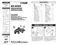
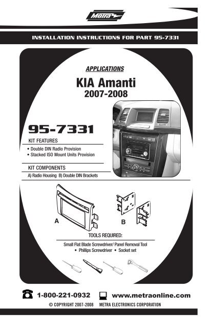
INSTALLATION INSTRUCTIONS FOR PART <strong>95</strong>-<strong>7331</strong><br />
APPLICATIONS<br />
<strong>KIA</strong> <strong>Amanti</strong><br />
2007-2008<br />
<strong>95</strong>-<strong>7331</strong><br />
KIT FEATURES<br />
• Double DIN Radio Provision<br />
• Stacked ISO Mount Units Provision<br />
KIT COMPONENTS<br />
A) Radio Housing B) Double DIN Brackets<br />
A<br />
B<br />
TOOLS REQUIRED:<br />
Small Flat Blade Screwdriver/ Panel Removal Tool<br />
• Phillips Screwdriver • Socket set<br />
1-800-221-0932<br />
www.metraonline.<strong>com</strong><br />
© COPYRIGHT 2007-2008 METRA ELECTRONICS CORPORATION
<strong>95</strong>-<strong>7331</strong><br />
Dash Disassembly<br />
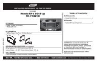
TABLE OF CONTENTS<br />
- <strong>KIA</strong> <strong>Amanti</strong> 2007-2008.......................................... 1,2<br />
Kit Assembly<br />
- Double DIN Radio Provision /Stacked ISO Mount Units Provision . . . . . . . . .3<br />
Final Assembly . . . . . . . . . . . . . . . . . . . . . . . . . . . . . . . . . . . . . . . . . . . 4<br />
*Note:<br />
Refer also to the instructions included with the aftermarket radio.
<strong>95</strong>-<strong>7331</strong> DASH DISASSEMBLY<br />
<strong>KIA</strong> AMANTI 2007-2008<br />
1<br />
Disconnect the negative battery terminal<br />
to prevent an accidental short<br />
circuit.<br />
A<br />
2<br />
3<br />
Unclip the top half of the shift knob<br />
and remove the “C” clip securing the<br />
shifter. Pull up on shifter to remove.<br />
(Figure A)<br />
Unclip and remove the panel surrounding<br />
the shifter. (Figure B)<br />
1 2 3<br />
4<br />
5<br />
Unclip and remove top half of center<br />
console including the cup holders.<br />
(Figure C)<br />
Open center console and remove<br />
screw cover in bottom. (Figure D)<br />
B<br />
6<br />
Remove (2) 10 MM bolts securing<br />
<strong>com</strong>partment then unclip and remove<br />
the <strong>com</strong>partment. (Figure D)<br />
Continue to kit assembly.<br />
D<br />
C<br />
1
<strong>95</strong>-<strong>7331</strong> DASH DISASSEMBLY<br />
<strong>KIA</strong> AMANTI 2007-2008<br />
7<br />
Unclip the rear trim panel from the<br />
center console including a/c vents.<br />
Unplug and remove the rear trim<br />
panel. (Figure E)<br />
E<br />
8 Remove (1) Phillips screw from each<br />
side at the rear of the center console.<br />
(Figure E)<br />
9<br />
Unclip the side panels from the front of<br />
the center console. It is not necessary<br />
to remove these panels. (Figure F)<br />
10 Remove (4) Phillips screws securing<br />
center console then lift and slide the<br />
center console back out of the way.<br />
Note: You do not have to take the center<br />
console all the way out. (Figure G)<br />
11 Remove (1) Phillips screw from each<br />
side panel then unclip and remove<br />
the side panels. (Figure H)<br />
12 Remove (4) Phillips screws securing<br />
the radio. Unplug and remove the<br />
radio.<br />
13 Unclip and remove the switches and/<br />
or switch covers along the top of the<br />
factory radio. (Retain switches<br />
and/or covers to be reinstalled in<br />
the radio housing.)<br />
Continue to kit assembly.<br />
F<br />
G<br />
H<br />
2
<strong>95</strong>-<strong>7331</strong> KIT ASSEMBLY<br />
DOUBLE DIN RADIO PROVISION<br />
STACKED ISO MOUNT UNITS PROVISION<br />
*Note: Refer also to the instructions included with the aftermarket radio.<br />
1<br />
2<br />
3<br />
Snap the switches into the radio housing<br />
in the same location as removed<br />
from the factory radio. (Figure A)<br />
Snap the Double DIN brackets to the<br />
inside edge of the Radio Housing.<br />
(Figure B)<br />
Slide the Double DIN Radio or stacked<br />
ISO Mount units into the bracket/radio<br />
housing assembly and secure to the<br />
assembly using the screws supplied<br />
with the radio or ISO mount units.<br />
(Figure C)<br />
Continue to final assembly.<br />
A<br />
B<br />
C<br />
3
<strong>95</strong>-<strong>7331</strong> FINAL ASSEMBLY<br />
FINAL ASSEMBLY<br />
A<br />
B<br />
C<br />
(A) Strip wire ends back 1/2"<br />
B) Twist ends together<br />
C) Solder<br />
D) Tape<br />
D<br />
1<br />
2<br />
3<br />
Locate the factory wiring harness in the dash. Metra re<strong>com</strong>mends using the<br />
proper mating adapter and making connections as shown. (Isolate and individually<br />
tape off the ends of any unused wires to prevent electrical short circuit.)<br />
Re-connect the negative battery terminal and test the unit for proper operation.<br />
Reassemble radio and dash assemblies in reverse order of disassembly.<br />
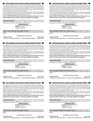
FINAL WIRING CONNECTIONS<br />
Make wiring connections using the EIA color code chart shown below and the instructions included with the<br />
head unit. Metra re<strong>com</strong>mends making connections as shown below; Strip, Splice, Solder, Tape. Isolate and<br />
individually tape off ends of any unused wires to prevent electrical short circuit.<br />
METRA / EIA WIRING CODE<br />
12V Ignition / Acc. . . . . . . . . . Red<br />
12V Batt / Memory. . . . . . . . . Yellow<br />
Ground. . . . . . . . . . . . . . . . . . Black*<br />
Power Antenna. . . . . . . . . . . . Blue<br />
Amp Turn-On . . . . . . . . . . . . . Blue / White<br />
Amp Ground. . . . . . . . . . . . . . Black / White<br />
Illumination . . . . . . . . . . . . . . Orange<br />
Dimmer . . . . . . . . . . . . . . . . . Orange / White<br />
Right Front (+) . . . . . . . . . . . . Gray<br />
Right Front (-). . . . . . . . . . . . . Gray/ Black<br />
Left Front (+) . . . . . . . . . . . . . White<br />
Left Front (-). . . . . . . . . . . . . . White / Black<br />
Right Rear (+) . . . . . . . . . . . . Violet<br />
Right Rear (-) . . . . . . . . . . . . . Violet / Black<br />
Left Rear (+) . . . . . . . . . . . . . Green<br />
Left Rear (-) . . . . . . . . . . . . . . Green / Black<br />
*NOTE: When a Black wire is not present, ground radio to vehicle chassis.<br />
All colors may not be present on all leads due to manufacturer’s specifications.<br />
4
<strong>95</strong>-<strong>7331</strong><br />
NOTES<br />
5
<strong>95</strong>-<strong>7331</strong> INSTRUCTIONS<br />
1-800-221-0932<br />
www.metraonline.<strong>com</strong><br />
REV. 02/26/08 © COPYRIGHT 2007-2008 METRA ELECTRONICS CORPORATION INST<strong>95</strong>-<strong>7331</strong>