Honda CR-V 2012-up 95-7802CH - Installer.com
Honda CR-V 2012-up 95-7802CH - Installer.com
Honda CR-V 2012-up 95-7802CH - Installer.com

Create successful ePaper yourself
Turn your PDF publications into a flip-book with our unique Google optimized e-Paper software.
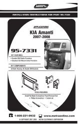
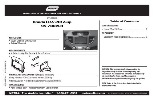
INSTALLATION INSTRUCTIONS FOR PART <strong>95</strong>-<strong>7802CH</strong><br />
KIT FEATURES<br />
• Double DIN head unit provision<br />
• Painted Charcoal<br />
APPLICATIONS<br />
<strong>Honda</strong> <strong>CR</strong>-V <strong>2012</strong>-<strong>up</strong><br />
<strong>95</strong>-<strong>7802CH</strong><br />
Table of Contents<br />
Dash Disassembly<br />
– <strong>Honda</strong> <strong>CR</strong>-V <strong>2012</strong>-<strong>up</strong> ........................................... 2<br />
Kit Assembly<br />
– Double DIN head unit provision ............................ 3<br />
KIT COMPONENTS<br />
• A) Radio Housing Trim Panel • B) Radio Brackets<br />
A<br />
B<br />
REV. 9/18/<strong>2012</strong> INST<strong>95</strong>-<strong>7802CH</strong><br />
WIRING & ANTENNA CONNECTIONS (sold separately)<br />
Wiring Harness: • 70-1729 <strong>Honda</strong> Harness 2008-Up<br />
Antenna Adapter: • 40-HD11 <strong>Honda</strong> Antenna Adapter 2009-Up<br />
TOOLS REQUIRED<br />
• Panel removal tool • Phillips screwdriver • Socket Wrench<br />
CAUTION: Metra re<strong>com</strong>mends disconnecting the<br />
negative battery terminal before beginning any<br />
installation. All accessories, switches, and especially<br />
air bag indicator lights must be plugged in<br />
beforereconnecting the battery or cycling the ignition.<br />
NOTE: Refer to the instructions included with the<br />
aftermarket radio.<br />
METRA. The World’s best kits. <br />
1-800-221-0932 metraonline.<strong>com</strong> © COPYRIGHT 2004-2011 METRA ELECTRONICS CORPORATION
<strong>95</strong>-<strong>7802CH</strong><br />
Dash Disassembly<br />
1. Unclip and remove the a/c vents<br />
from either side of the factory<br />
radio. (Figure A)<br />
2. Remove (4) Phillips screws<br />
securing the radio. (Figure B)<br />
3. Remove (2) Phillips screws<br />
securing the factory hazard button<br />
to the factory radio trim panel.<br />
(Figure C)<br />
4. Remove the (6) panel clips from<br />
the factory radio trim panel and<br />
save for Kit Assembly.<br />
Continue to kit assembly<br />
(Figure A) (Figure B)<br />
(Figure C)<br />
2
<strong>95</strong>-<strong>7802CH</strong><br />
Kit Assembly<br />
1. Attach the (6) factory panel clips to<br />
the radio housing. (Figure A)<br />
2. Attach the factory hazard button<br />
to the 7802 radio panel using the<br />
factory screws. (Figure B)<br />
Double DIN head unit provisions<br />
1. Attach the DDIN radio brackets to<br />
the Double DIN head unit using the<br />
screws s<strong>up</strong>plied with the unit.<br />
2. Locate the factory wiring harness<br />
and antenna plug in the dash.<br />
Metra re<strong>com</strong>mends using the<br />
proper mating adapters from<br />
Metra and/or AXXESS.<br />
3. Mount the new radio assembly into<br />
(Figure A) the dash and reassemble dash in<br />
reverse order of disassembly.<br />
(Figure A)<br />
(Figure B)<br />
3
INSTALLATION INSTRUCTIONS FOR PART <strong>95</strong>-<strong>7802CH</strong><br />
REV. 9/18/<strong>2012</strong> INST<strong>95</strong>-<strong>7802CH</strong><br />
KNOWLEDGE IS POWER<br />
Enhance your installation and fabrication skills by<br />
enrolling in the most recognized and respected<br />
mobile electronics school in our industry.<br />
Log onto www.installerinstitute.<strong>com</strong> or call<br />
800-354-6782 for more information and take steps<br />
toward a better tomorrow.<br />
Metra re<strong>com</strong>mends MECP<br />
certified technicians<br />
METRA. The World’s best kits. <br />
1-800-221-0932 metraonline.<strong>com</strong> © COPYRIGHT 2004-2011 METRA ELECTRONICS CORPORATION