602 KB - ipcas
602 KB - ipcas
602 KB - ipcas

Create successful ePaper yourself
Turn your PDF publications into a flip-book with our unique Google optimized e-Paper software.
ipEther232.PPP<br />
User Guide<br />
<strong>ipcas</strong> GmbH<br />
Wetterkreuz 17<br />
D-91058 Erlangen<br />
Telefon: +49 9131 7677 0<br />
Telefax: +49 9131 7677 78<br />
Internet: http://www.<strong>ipcas</strong>.de<br />
E-Mail: info@<strong>ipcas</strong>.de
Legal Information for Customers<br />
We have done our utmost to ensure that the information in this<br />
user guide is complete, accurate and up to date. In so far as legally<br />
possible, we cannot accept any liability for consequential damage<br />
caused by using this guide. In other respects we shall accept<br />
liability for intention and gross negligence only. We cannot provide<br />
any warranty that changes to third-party equipment referred to in<br />
this guide will have no effect on the applicability of the information<br />
provided in this guide.<br />
The author reserves all rights, including the right to reproduce this<br />
guide in full or part thereof in any form whatsoever.<br />
The content is subject to change without prior notification.<br />
The product is subject to technical change without prior notification.<br />
All trade marks mentioned in this manual are stated for<br />
identification purposes and may be the property of the various<br />
holders.<br />
Important Information<br />
• The device should be used exclusively with the mains unit<br />
supplied. Using a different power supply unit may result in damage<br />
to the device.<br />
• Use a dry cloth only to clean the operating panel and the housing.<br />
• If the device is damaged, disconnect from the mains. Arrange for<br />
immediate repair.<br />
• Before contacting your vendor's customer service, please consult<br />
this user guide.<br />
• Using customer service during the warranty period may incur<br />
costs, if the fault or problem was caused by the customer and the<br />
solution or remedy is described in this guide.<br />
• Removing the serial number will void the warranty rights.<br />
• Damage caused by inappropriate packing will not be borne by<br />
the forwarding agent / insurance company.<br />
Note !<br />
ipEther232 is a Class A device. This device can cause interferences<br />
to radio communications in residential areas; in such cases the<br />
operator may be ordered to carry out and pay for appropriate<br />
measures.<br />
This warning does not apply to desktop housing or the OEM version<br />
w ithout housing.<br />
Subject o mod ificatio ns.<br />
Last Update27.02.04<br />
<strong>ipcas</strong> GmbH ipEther232.PPP V9.01 Page 2 of 32
Important Safety Information<br />
As is the case with all electrical equipment there are some basic<br />
safety precautions to be observed. These safety precautions are<br />
primarily for you own safety but also serve to prevent damage to<br />
the device.<br />
Settings not described in this guide and changes to the device<br />
electronics are to be carried out by an authorized vendor only.<br />
Read the user guide carefully and keep it to hand.<br />
Make sure that...<br />
Install the device<br />
• the device is placed on a stable, flat surface;<br />
• for rail mounted devices the top hat rail is sufficiently grounded<br />
and the rail spring has good contact;<br />
• the device is never placed near a heater or the air outlet of an<br />
air-conditioning unit;<br />
• the device is never exposed to direct sunlight;<br />
• the device is never in direct contact with liquids of any kind.<br />
Never use liquids in the vicinity of the device.<br />
• Opening the housing may lead to an electric shock and other<br />
damage. Never make any changes to the device that are not<br />
described in the user guide. This could result in damage to the<br />
device and you would have to pay for the repairs. Only the<br />
authorized vendor may modify the input voltage, should this<br />
become necessary.<br />
Make sure that...<br />
• the mains supply values are the same as the designation on the<br />
power supply unit. In case of doubt contact your supplier.<br />
• the mains is protected against surges and other disturbances.<br />
• the mains socket is located near the device and is easily<br />
accessible.<br />
• you pull the mains plug completely to disconnect.<br />
• the maximum power rating of an extension cable or multiple<br />
contact plug, if used, is not exceeded.<br />
• the mains cable is protected against damage. Do not place<br />
anything on the cable and put it down, so that there is no danger<br />
of stepping on or tripping over it.<br />
• a damaged mains cable is replaced immediately.<br />
• the mains cable is disconnected before starting to clean the<br />
device. Use a dry cloth only. Do not use any liquid or aerosol<br />
cleaning agent.<br />
Subject o mod ificatio ns.<br />
Last Update27.02.04<br />
<strong>ipcas</strong> GmbH ipEther232.PPP V9.01 Page 3 of 32
Please follow all warnings and instructions displayed on the device itself<br />
and in accompanying manuals. In the manual, warnings of particular<br />
importance are marked by the symbols below.<br />
Warning and important information symbols<br />
NOTE: Text sections marked in this way contain supplementary information or hints.<br />
WARNING- Damage: This warns against possible damage to the device. Follow all<br />
instructions to avoid damage.<br />
CAUTION - Danger of Injury: This points out a possible source of danger. Follow all<br />
safety instructions to avoid injury.<br />
CAUTION - Hot: This points out a possible source of danger. Follow all safety<br />
instructions to avoid heat-related injury.<br />
CAUTION - Current: This points out a possible source of danger. Follow all safety<br />
instructions to avoid injury through electrocution.<br />
Subject o mod ificatio ns.<br />
Last Update27.02.04<br />
<strong>ipcas</strong> GmbH ipEther232.PPP V9.01 Page 4 of 32
Contents<br />
Page<br />
Chapter 1: The Device .............................................................6<br />
1.1 Usage............................................................................................................................. 6<br />
1.2 Sockets.......................................................................................................................... 8<br />
Chapter2: Commissioning ipEther232.PPP......................9<br />
2.1 Commissioning............................................................................................................. 9<br />
2.2 Set the IP address....................................................................................................... 9<br />
2.3 Logfile...........................................................................................................................11<br />
2.4 Configuration...............................................................................................................13<br />
Chapter 3: Technical Details..............................................14<br />
3.1 Specifications..............................................................................................................15<br />
3.2 Pin Assignment...........................................................................................................16<br />
3.2.1 RS232 Connection Cable......................................................................................18<br />
3.2.2 Power Supply Units................................................................................................21<br />
3.2.3 RS232.Modem Module..........................................................................................21<br />
3.2.4 RS232 Module.........................................................................................................22<br />
3.2.5 RS485 Module.........................................................................................................22<br />
3.2.6 RS485 as a 2 Wire solution...................................................................................23<br />
3.3 Measurements............................................................................................................24<br />
3.4 Declaration of EEC Compliance..............................................................................27<br />
3.5 FAQ’s ...........................................................................................................................28<br />
3.6 Glossary.......................................................................................................................32<br />
Subject o mod ificatio ns.<br />
Last Update27.02.04<br />
<strong>ipcas</strong> GmbH ipEther232.PPP V9.01 Page 5 of 32
Chapter 1: The Device<br />
1.1 Usage<br />
The PPP / Ethernet – Converter enables the transmission of network packets via<br />
a serial interface from and to the Ethernet (PPP = Point to Point Protocol).<br />
With ipEther232.PPP all these (serial) devices can be linked up to an Ethernet<br />
LAN via TCP/IP and thus also to the internet or your company intranet.<br />
The PPP gateway solution works with all operating systems and is compatible<br />
with existing PPP applications. You can start several services (ftp, telnet, www,<br />
ssh, rsh, rcp etc.) simultaneously via this transparent network connection.<br />
1.) "Ethernet for all"<br />
Ethernet capability for all TCP/IP<br />
enabled devices w ithout a dedicated<br />
Ethernet interface, such as:<br />
- Embedded PC<br />
- SPS<br />
- PC<br />
- Notebook<br />
- Modem<br />
- Router<br />
- Pa lm<br />
Subject o mod ificatio ns.<br />
Last Update27.02.04<br />
<strong>ipcas</strong> GmbH ipEther232.PPP V9.01 Page 6 of 32
2.) "simple Network routing"<br />
Simple routing betw een two<br />
netw orks via GSM, ISDN or analog<br />
modems, for instance to link up a<br />
branch to the company LAN.<br />
3.) "dial in"<br />
Enables company LAN access for<br />
home office, remote maintenance or<br />
for field reps.<br />
Subject o mod ificatio ns.<br />
Last Update27.02.04<br />
<strong>ipcas</strong> GmbH ipEther232.PPP V9.01 Page 7 of 32
1.2 Sockets<br />
ipEther232.PPP has three sockets:<br />
• Ethernet (10BaseT) for a 10/100 Mbit network<br />
• RS232 SUB-D 9<br />
• Power supply 9V DC or 24VDC or 48/60V DC<br />
A diagram of all connectors and their designation is displayed on the housing.<br />
RS232<br />
SUB-D 9 Pin<br />
Ethernet<br />
10/100<br />
RJ45<br />
9V DC<br />
The LEDs indicate the device state and have the following meaning:<br />
• POWER The device is switched on.<br />
• System Slow flashing indicates that at the moment there is no<br />
connection to a PC. Fast flashing indicates that the<br />
device is in use.<br />
• LINK LAN There is a physical connection to the network.<br />
• LAN Rx Packets are received via the Ethernet.<br />
• LAN Tx Packets are sent to the Ethernet.<br />
• V24 Rx Data is received via the RS232 line.<br />
• V24 Tx Data is sent via the RS232 line.<br />
• Error Errors have occured in the RS232 line.<br />
Subject o mod ificatio ns.<br />
Last Update27.02.04<br />
<strong>ipcas</strong> GmbH ipEther232.PPP V9.01 Page 8 of 32
Chapter2: Commissioning ipEther232.PPP<br />
2.1 Commissioning<br />
Connect the device to the mains. The "Power" signal and the flashing "System"<br />
LED indicate that ipEther232 is ready for operation.<br />
ipEther232 is connected to the network via an RJ45 socket.<br />
The "Link LAN" LED (connection) indicates the connection to the LAN.<br />
If this is not the case, check the netwok connection or network line.<br />
The enclosed CD contains a modem driver set-up program and the configuration<br />
tool. The modem driver runs on all windows NT based operating systems, as well<br />
as Windows NT 4 from SP5, Windows 2000 and Windows XP.<br />
No PC reboot is necessary after installation. The configuration tool for configuring<br />
the device starts automatically after installation.<br />
For later configuration sessions the program is included in the<br />
"Program Files / ipEther232.Modem" folder.<br />
2.2 Set the IP address<br />
On delivery of ipEther232, no valid IP address has been set (Default: 10.10.5.1).<br />
To start with, each device must be allocated an unambiguous IP address.<br />
The IP address can be obtained from the network administrator. It must comply<br />
with your network and cannot be assigned twice.<br />
In order to set the IP address in your ipEther232, the device must be connected<br />
to its own network segment. If need be, connect the device via a "cross over"<br />
cable to the PC.<br />
The configuration program recognizes all devices in its own network segment,<br />
even if they do not have a valid IP address. Double-click on the device entry to<br />
call up a dialog, where you can enter a valid IP address and further<br />
configurations.<br />
Subject o mod ificatio ns.<br />
Last Update27.02.04<br />
<strong>ipcas</strong> GmbH ipEther232.PPP V9.01 Page 9 of 32
The entry "State" has the follow ing meaning:<br />
• "not found"<br />
The device could not be located anymore. It is not connected, switched off or<br />
has been connected after a router blocking the UDP Port 3497.<br />
• "connected"<br />
The device has been located and can be addressed via the entered IP<br />
address.<br />
• "connected via router"<br />
The device has been located and installed after the router. The IP address<br />
cannot be changed.<br />
• "found but unreachable"<br />
The device has been located in the own network segment, but could not be<br />
accessed via the entered IP address. Check whether the entered IP address<br />
is valid for your network.<br />
• "in use"<br />
The device is in use at the moment. The parameters cannot be changed.<br />
Subject o mod ificatio ns.<br />
Last Update27.02.04<br />
<strong>ipcas</strong> GmbH ipEther232.PPP V9.01 Page 10 of 32
If ipEther232s are connected after a router, they are not automatically detected.<br />
They must be entered manually ("Add manually"). This is done by entering their<br />
IP address. If the device can be accessed via this address, it is included in the<br />
list.<br />
If the device is installed after a router, the IP address cannot be changed. This<br />
prevents that the device accidentally becomes inaccessible.<br />
2.3 Logfile<br />
Any errors occurring during communication are written to a logfile ("Show<br />
Errors") for later analysis. You can find the errors in the "Programm-<br />
Path"\ERRORS.LOG file.<br />
Subject o mod ificatio ns.<br />
Last Update27.02.04<br />
<strong>ipcas</strong> GmbH ipEther232.PPP V9.01 Page 11 of 32
2: ERR_RXDBufferOverrun<br />
The UART (RS232) receivebuffer is overruned.<br />
4: ERR_NICOv errun<br />
The NIC (Network Interface Controller) receivebuffer is overruned.<br />
5: ERR_SETUP_BAUD,<br />
6: ERR_SETUP_PARITY,<br />
7: ERR_SETUP_DATA<br />
The UART (RS232) parameter is incorrect. Please use the configurationtool<br />
to set the correct RS232 parameters.<br />
9: ERR_UART_OVERRUN<br />
Overrun Error Bit from received controlregister (UART) would be ignored.<br />
10: ERR_UART_FRAME<br />
Framing Error Bit from received controlregister (UART) would be ignored.<br />
18: ERR_NIC_INTERNAL<br />
The DMA operation on the networkcontroller (NIC) could not lead through.<br />
23: ERR_PPP_BUFFER_OVERRUN_ETH<br />
The Ethernet IP buffer is full. The incoming IP Packet has been ignored.<br />
24: ERR_PPP_BUFFER_OVERRUN_PPP<br />
The PPP (RS232) IP buffer is full. The incoming IP Packet has been ignored.<br />
25: ERR_PPP_INVALID_MESSAGE<br />
A wrong LCP or IPCP information would be received. The PPP Packet has<br />
been ignored.<br />
(Defaults for the PPP Protocol – RFC1661, RFC1662, RFC1332)<br />
28: ERR_PPP_CRC<br />
A PPP Packet with wrong checksum (FCS) has been received. This Packet<br />
has been ignored.<br />
31: PPP_IPCP_UP<br />
The LCP und IPCP authentication has been lead through. The PPP<br />
connection has been established.<br />
32: PPP_IPCP_DOWN<br />
The PPP connection has been disconnected.<br />
33: ERR_INVALID_CONFIG<br />
A invalid parameter would be established after the connect. In this case the<br />
defaultparameter would be loaded. Please execute the configurationtool<br />
again. If the MAC Address does no more agree please contact your<br />
34: ERR_WDT_ TIMEOUT<br />
Processorreset because of „Watchdog Timeout“<br />
35: ERR_NORMAL_POWER_UP<br />
Processorreset because of „Watchdog Timeout“<br />
36: ERR_MCLR_FROM_SLEEP<br />
Processorreset because of „SLEEP“<br />
37: ERR_BROWNOUT_RESTART<br />
Prozessorreset auf Grund von Spannungsschwankungen<br />
Processorreset because of main disturbances<br />
Subject o mod ificatio ns.<br />
Last Update27.02.04<br />
<strong>ipcas</strong> GmbH ipEther232.PPP V9.01 Page 12 of 32
2.4 Configuration<br />
The Configuration menu consists of five parts:<br />
TCP/IP (Ethernet):<br />
This tells you the device ID, i.e. the<br />
ipEther232.PPP serial number and the<br />
network settings for the Ethernet side are<br />
configured here.<br />
(Default Gateway or no Gateway = 0.0.0.0)<br />
TCP/IP (PPP):<br />
This is where you can set the IP address<br />
for the serial side, or specify that it comes<br />
from a DHCP server or from the Caller.<br />
Default here means that there is no<br />
synchronization between PPP partners<br />
with respect to the IP address.<br />
RS232:<br />
Baud rate, Parity and Stop bits are adapted<br />
to the communication behavior of the serial<br />
terminal device.<br />
The default 0 disables this function.<br />
Modem settings:<br />
The modem behavior is defined here.<br />
Typically the Hayes commands are used in<br />
the .init string for communicating with the<br />
modem. Please refer to your modem user<br />
guide for these commands.<br />
Enter the phone number of the call<br />
recipient in the appropriate field. "Idle<br />
timeout" specifies the time in minutes after<br />
which the modem disconnects. "Max.<br />
online" specifies the maximum time span<br />
after which the modem connection is cut.<br />
Completion to TCP/IP (PPP):<br />
• "MRU-Size" specifies the maximum IP packet size. The default is 1500.<br />
• "ASYNC-MAP". The entry format is hexadecimal code. Default is 0.<br />
• Magicnumber: Default: "Off”.<br />
• Protocol Compression: Default: "Off”.<br />
• Address Compression: Default: "Off”.<br />
The above parameters are described in more detail in the RFC-1661 and RFC-1662.<br />
Firmw are:<br />
This tells you the firmware release. You can update to the most current version. The latest<br />
firmware releases can be found under www.<strong>ipcas</strong>.de. We recommend that you update only<br />
when there is a real need to do so.<br />
Subject o mod ificatio ns.<br />
Last Update27.02.04<br />
<strong>ipcas</strong> GmbH ipEther232.PPP V9.01 Page 13 of 32
Chapter 3: Technical Details<br />
Great emphasis was placed on compatability during device design.<br />
There are, however, some minor restrictions:<br />
• ipEther232.PPP can store 20 Ethernet packets that are then transmitted<br />
to the RS232 or the Ethernet side. If additional packets arrive before<br />
memory has been freed, the packet is discarded. This is however<br />
reported and written to the error logfile (see Config tool). The problem<br />
only occurs if too many connections are open at the same time or too<br />
many unacknowledged packets are sent at the same time (Windows size<br />
too large or UAP connections).<br />
• The ARP cache can hold 20 entries. If the PPP side requires more ARP<br />
entries, the oldest entry is deleted. This might however have an adverse<br />
effect on the performance.<br />
• ipEther232.PPP principally uses the "hardware handshake".<br />
• Should problems arise, we recommend testing the connection with Linux<br />
PPPD.<br />
• IPCP is not supported.<br />
UART<br />
The UART supports transmission speeds between 2400 baud and 115200 baud.<br />
Higher baud rates might result in data loss, if data is transmitted continuously.<br />
The device uses 8 Data bits and "no parity".<br />
Subject o mod ificatio ns.<br />
Last Update27.02.04<br />
<strong>ipcas</strong> GmbH ipEther232.PPP V9.01 Page 14 of 32
3.1 Specifications<br />
Constructional execution<br />
Housing<br />
Measurements<br />
Weight:<br />
Desktop device<br />
DIN-Rail Unit<br />
Power suppl y<br />
Voltage supply<br />
Desktop device<br />
DIN-Rail Unit –H24<br />
DIN-Rail Unit –H60<br />
Capacit y<br />
Desktop device<br />
DIN-Rail Unit –H24<br />
DIN-Rail Unit –H60<br />
External power supply 1<br />
AC voltage<br />
DC voltage<br />
Operati ng temperature<br />
Rel. Dampness<br />
External power supply 2<br />
AC voltage<br />
DC voltage<br />
Operati ng temperature<br />
Rel. Dampness<br />
Safet y class<br />
Climate tests<br />
Recommended operatingt emperat ure<br />
Operati ngtemperature li mit<br />
Store- and trans portt emperature<br />
Rel. Dampness<br />
Serial interface<br />
Connection<br />
Pin alloc ation<br />
Configuration<br />
Baud rate<br />
Parity<br />
Databits<br />
Stopbits<br />
Cable length in offic e environment<br />
At RS485<br />
Ethernet interface<br />
Connection<br />
TCP/IP<br />
Diagnosis (LED)<br />
Firmware<br />
Drivers<br />
Plastic housing<br />
See M easur ements<br />
approx. 150 g<br />
approx. 180 g<br />
approx. 180 g<br />
(AC – Versions on reply)<br />
9 V DC (8 – 14 V DC ± 5 %)<br />
24 V DC (18 – 36 V DC ± 5 %)<br />
60 V DC (18 – 72 V DC ± 5 %)<br />
Optionall y available: 18 - 48 V AC<br />
at nomi nal Voltage (typical t erm)<br />
9 V DC 80 mA ca. 0,8 W<br />
24 V DC 60 mA ca. 1,44 W<br />
60 V DC 40 mA ca. 2,4 W<br />
230 V AC 50 Hz approx. 6, 3 VA<br />
9 V DC approx. 2,25 VA<br />
0°C to +40°C<br />
5 % t o 90 % non-condensing<br />
100 – 240 V AC 50 / 60 Hz approx. 12, 6 VA<br />
9 V DC approx. 8,1 VA<br />
0°C to +40°C<br />
5 % t o 90 % non-condensing<br />
II / III<br />
+10°C to +50°C<br />
+5°C to +55°C<br />
-10°C to +70°C<br />
5 % t o 90 % non-condensing<br />
9-pin Sub-D Soc ket full alloc ation<br />
see Pi n alloc ation<br />
2400 to 115200 Baud<br />
None, Even, O dd, Mar k, Spac e<br />
7 or 8 Bits (Exc epti on 7N1)<br />
1 or 2 Bits<br />
RS232 up to 10 m<br />
RS485 up to 500m<br />
2 / 4 wire solution<br />
Transmit dat a optionall y ins ertabl e (RTS or CTS)<br />
10BaseT<br />
RJ45<br />
UDP Port 3497<br />
ICMP<br />
ARP<br />
Power, System, Error, Link,<br />
EthR xD, EthT xd<br />
Rs232 R xD, T xD<br />
Updat eable<br />
Setup & configurationtool<br />
for Windows NT4 / 2000 / XP<br />
Norms EN 55022/1998<br />
EN 50082-2/1997<br />
Subject o mod ificatio ns.<br />
Last Update27.02.04<br />
<strong>ipcas</strong> GmbH ipEther232.PPP V9.01 Page 15 of 32
3.2 Pin Assignment<br />
SERIAL PORT<br />
RS232 DCE (Modem)<br />
DB9 Connector female<br />
Pin Direction Definition<br />
1 OUTPUT DCD Data Carrier Detect<br />
2 OUTPUT RXD Receive Data<br />
3 INPUT TXD Transmit Data<br />
4 INPUT DTR Data Terminal Ready<br />
5 GND Ground<br />
6 OUTPUT DSR Data Set Ready<br />
7 INPUT RTS Request To Send<br />
8 OUTPUT CTS Clear To Send<br />
9 OUTPUT RI Ring Indicator<br />
SERIAL PORT<br />
RS232 DTE (Computer)<br />
DB9 Connector male<br />
Pin Direction Definition<br />
1 INPUT DCD Data Carrier Detect<br />
2 INPUT RXD Receive Data<br />
3 OUTPUT TXD Transmit Data<br />
4 OUTPUT DTR Data Terminal Ready<br />
5 GND Masse<br />
6 INPUT DSR Data Set Ready<br />
7 OUTPUT RTS Request To Send<br />
8 INPUT CTS Clear To Send<br />
9 INPUT RI Ring Indicator<br />
SERIAL PORT<br />
RS485<br />
DB9 Connector male<br />
Pin Direction Definition<br />
1 NC<br />
2 OUTPUT TX+ (Send data)<br />
3 OUTPUT TX- (Send data)<br />
4 NC<br />
5 GND Masse<br />
6 INPUT RX+ (Receive Data)<br />
7 INPUT RX- (Receive Data)<br />
8 NC<br />
9 NC<br />
Subject o mod ificatio ns.<br />
Last Update27.02.04<br />
<strong>ipcas</strong> GmbH ipEther232.PPP V9.01 Page 16 of 32
Ethernet Connector<br />
RJ 45 Pin Name Definition<br />
1 TX+ Transceive Data+<br />
2 TX- Transceive Data-<br />
3 RX+ Receive Data+<br />
4 n/c Not used<br />
5 n/c Not used<br />
6 RX- Receive Data-<br />
7 n/c Not used<br />
8 n/c Not used<br />
Subject o mod ificatio ns.<br />
Last Update27.02.04<br />
<strong>ipcas</strong> GmbH ipEther232.PPP V9.01 Page 17 of 32
3.2.1 RS232 Connection Cable<br />
Whichever Device is used, you have to choose the complying connection cable.<br />
From the following graphics you can take out the information to your needed<br />
connection cable.<br />
(also shown at Chapter Pin Allocation)<br />
For ipEther232 und ipEther232.PPP "DTE-Device"<br />
For ipEther232.Modem "DCE-Dev ice"<br />
Subject o mod ificatio ns.<br />
Last Update27.02.04<br />
<strong>ipcas</strong> GmbH ipEther232.PPP V9.01 Page 18 of 32
3.2.2 Pin Assignment ipEther232.PPP OEM<br />
Subject o mod ificatio ns.<br />
ipEther V2.1 Pin assignment of interfaces:<br />
Last Update27.02.04<br />
<strong>ipcas</strong> GmbH ipEther232.PPP V9.01 Page 19 of 32
J1: LAN interface<br />
1 TX+ 3 RX+<br />
2 TX- 6 RX-<br />
J4: RS232- / RS485 interface<br />
1 CD / - 6 DSR / RX+<br />
2 RXD / TX+ 7 RTS / RX-<br />
3 TXD / TX- 8 CTS / -<br />
4 DTR / - 9 RI / -<br />
5 GND/GND<br />
J6: LAN interface (OEM)<br />
1 TX+ 3 RX+<br />
2 TX- 4 RX-<br />
J7: LED interface (OEM)<br />
1 +5V 6 LED_LAN_RXD<br />
2 LED_POWER 7 LED_LAN_TXD<br />
3 LED_SYSTEM 8 LED_SYSTEM2<br />
4 LED_COM_TXD 9 LED_LAN_LINK<br />
5 LED_COM_RXD 10 GND<br />
J8: Module interface<br />
1 CD 6 RTS / RX-<br />
2 DSR / RX+ 7 TXD / TX-<br />
3 RXD / TX+ 8 DTR<br />
4 CTS 9 DTR_TTL<br />
5 RI<br />
J9: Module interface<br />
1 +5V 6 CTS_TTL<br />
2 GND 7 RI_TTL<br />
3 CD_TTL 8 RTS_TTL<br />
4 DSR_TTL 9 TXD_TTL<br />
5 RXD_TTL<br />
J10: RS232- / RS485 interface (OEM)<br />
1 CD / - 6 CTS / -<br />
2 DSR / RX+ 7 DTR / -<br />
3 RXD / TX+ 8 RI / -<br />
4 RTS / RX- 9 GND<br />
5 TXD / TX- 10 n/c<br />
JP6: Supply voltage input (OEM)<br />
1 GND 2 Vin+ (8 – 14 VDC)<br />
JP7: 5V Supply voltage input (OEM)<br />
1 GND 2 +5V<br />
Subject o mod ificatio ns.<br />
Last Update27.02.04<br />
<strong>ipcas</strong> GmbH ipEther232.PPP V9.01 Page 20 of 32
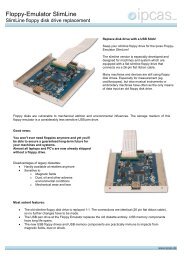
3.2.2 Power Supply Units<br />
(18-36 V DC or 18-72 V DC with polarity protection)<br />
Remove all 4 jumpers (JP6 & JP7) and mount power<br />
supply unit with spacer and fastening screw.<br />
3.2.3 RS232.Modem Module<br />
Together with this module, ipEther232 is covered by<br />
the ipEther232.Modem user guide, they are<br />
mentioned here to complete the list.<br />
No optional settings.<br />
Subject o mod ificatio ns.<br />
Last Update27.02.04<br />
<strong>ipcas</strong> GmbH ipEther232.PPP V9.01 Page 21 of 32
3.2.4 RS232 Module<br />
This user guide refers to the displayed module<br />
together with ipEther232.PPP<br />
No optional settings.<br />
3.2.5 RS485 Module<br />
This user guide covers ipEther232 used with this module.<br />
The RS485 transmitter can either be used in continuous operation, e.g. for pointto-point<br />
connections, or it can be triggered by software. This option is enabled by<br />
jumpers.<br />
The factory setting is continuous operation.<br />
RS485 Module<br />
Br. 3<br />
Br. 2<br />
Br. 1<br />
Jumper J. 1 J. 2 J. 3<br />
Transmitter in continuous - - X<br />
operation.<br />
switch on by DTR X - -<br />
switch on by RTS - X -<br />
X = closed<br />
- = open<br />
Subject o mod ificatio ns.<br />
Last Update27.02.04<br />
<strong>ipcas</strong> GmbH ipEther232.PPP V9.01 Page 22 of 32
3.2.6 RS485 as a 2 Wire solution<br />
A closing of the cables with termination-networks is needed at RS485-<br />
connections to force the silencelevel on the bussystem while no datatransmitter is<br />
active.<br />
VCC<br />
RX+<br />
TX+<br />
R1 390 Ω<br />
R2 220 Ω<br />
RX+<br />
TX+<br />
RX-<br />
TX-<br />
R3 390 Ω<br />
RX-<br />
TX-<br />
GND<br />
Please take the pin allocation from the chapter 3.2 Pin Allocation<br />
Subject o mod ificatio ns.<br />
Last Update27.02.04<br />
<strong>ipcas</strong> GmbH ipEther232.PPP V9.01 Page 23 of 32
Diagnosis p anel with 8 L EDs:<br />
SYSTEM<br />
RXD V24<br />
RX LAN<br />
LINK LAN<br />
-<br />
POWER<br />
V24 T XD<br />
LAN TX<br />
ERROR<br />
18,4<br />
RS232 DB9 Socket<br />
30,8<br />
Ethernet Connector<br />
10BaseT ( RJ45)<br />
15,2<br />
8,8<br />
6,2<br />
Power Supply<br />
14, 0<br />
11, 5<br />
1,5<br />
8,0<br />
12, 5<br />
13, 0<br />
15,1<br />
51, 0<br />
77,7<br />
Circuit Board<br />
90, 7<br />
100,0<br />
6,0<br />
4,0<br />
2,0<br />
2,0<br />
69, 1<br />
Subjec t t o modific ations<br />
3.3 Measurements<br />
Appr.<br />
1.009 Page<br />
1<br />
Gen. Tolerances:<br />
Datum<br />
Name<br />
Mod.. 15. 03. 02 P. Felbi nger<br />
Scale: 1 : 1<br />
ipEther232 (OEM V1)<br />
Creat.for<br />
:<br />
Page<br />
Creat.by:<br />
St. Modification Date Name Orig.<br />
Subject o mod ificatio ns.<br />
Last Update27.02.04<br />
<strong>ipcas</strong> GmbH ipEther232.PPP V9.01 Page 24 of 32
Subject o mod ificatio ns.<br />
Last Update27.02.04<br />
<strong>ipcas</strong> GmbH ipEther232.PPP V9.01 Page 25 of 32
Subject o mod ificatio ns.<br />
Last Update27.02.04<br />
<strong>ipcas</strong> GmbH ipEther232.PPP V9.01 Page 26 of 32
3.4 Declaration of EEC Compliance<br />
is assured for the following product<br />
ipEther232<br />
This company confirms that the product complies with the main specifications for the<br />
protection against harmful interference laid down in the Council Guidelines on Harmonizing<br />
the Statutory Regulations of the Member States for Electromagnetic Compatibility<br />
(89/336/EEC).<br />
Any modifications to ipEther232 not authorized by this company invalidates this declaration.<br />
This product was tested and evaluated for electromagnetic compatibility in accordance with<br />
the following standards:<br />
EN 55022/1998<br />
EN 50082-2/1997<br />
Place/Date/Manufacturer's Signature: Erlangen, 09 April 2002 ________<br />
____<br />
Title of the Undersigned:<br />
Managing Director, Dipl.-Ing. Suganda Sutiono<br />
Subject o mod ificatio ns.<br />
Last Update27.02.04<br />
<strong>ipcas</strong> GmbH ipEther232.PPP V9.01 Page 27 of 32
3.5 FAQ’s<br />
1. Generally: Do I have w ith each configuration (Virtual com port) on different<br />
workstations the IP to again configure?<br />
No, the IP of the Serial-Ethernet-Converter must be configured only on the<br />
first installation. But for any further Workstation you have to install the<br />
Virtual COM-Port driver. The IP-Address has to be the same, so that all<br />
already installed COM-Ports haven further function.<br />
2. Generally: Does ipEther232 function ov er routs?<br />
Yes, but for the first configuration you have to connect the Ethernet-<br />
Converter to the own Subnet. Afterwards you have also Router access over<br />
the Configuration-Tool (Add Device manually).<br />
3.Generally:<br />
4.Generally:<br />
5.Generally:<br />
6.Generally:<br />
7.Generally:<br />
8.Generally:<br />
9.Generally:<br />
10.Generally:<br />
11.Generally:<br />
Where can one configure the "subnet mask"?<br />
That is not necessarily, because the Virtual COM-Port driver use the<br />
Network-environment standard gateway and subnet mask.<br />
Is alternately used mode RS232/485 possible? How does one switch<br />
between RS232 and RS485? Do the two modes run over the same DB9<br />
Port?<br />
Alternate is not to be switched between these modes. RS232 and RS485<br />
have different bus drivers within the devices. But there are separate devices<br />
and order numbers.<br />
How many ipether232 can be managed with one w orkstation?<br />
Up to 254 Seral-Ethernetconverter (256 Com-Ports are possible but Com1<br />
and Com2 are physically already present).<br />
Why isn't the serial interface of the ipEther232 indicated in the device<br />
manager?<br />
The serial interface of the ipEther232 is not recognized in the device<br />
manager, because it concerns a virtual interface and not around a physical<br />
COM interface in the PC.<br />
Can serial devices be used with ipEther232 also via Internet?<br />
Yes, the ipEther232 makes the access possible to the serial device over the<br />
local Ethernet. The TCP/IP protocol is used for it. TCP/IP forms the basis of<br />
the Ethernet.<br />
Is it possible to build with only 2 wires communication between the<br />
RS485 interface of the ipEther232 and serial device on?<br />
It is possible. Please look for this in our manual in the section 3.2.6 RS485<br />
as a 2 wire solution (at present P. 21).<br />
Are there 2 wire solution for the ipEther232 with RS232 interface also?<br />
Yes. Only pin 2 (RXD Receiver Data), pin 3 (TXD Transmit Data) and mass<br />
(GND) are needed. In addition it can be necessary to activate of<br />
"NoModemSignals" in the Configtool. This can take place alternatively also<br />
via durable bridging of pin 4 (DTR Data Terminal Ready) and pin 6 (DSR<br />
Data Set Ready). For Pin allocation, please see the manual.<br />
Why doesn't the ipEther232 function with 1200 baud?<br />
The ipEther232 supports the speeds of 2400-115200 Baud. If you need<br />
1200 Baud, contact us please.<br />
Which supply v oltages are offered for ipEther232?<br />
9V DC, 18-36V DC, 18-27V DC<br />
Other tensions on request.<br />
Subject o mod ificatio ns.<br />
Last Update27.02.04<br />
<strong>ipcas</strong> GmbH ipEther232.PPP V9.01 Page 28 of 32
12.Generally:<br />
13.Generally:<br />
How can I accomplish an analysis of my serial connection ov er<br />
ipEther232?<br />
You can use Tools like PortMon(serial connection) and CommView or<br />
Ethereal (network connection) for it.<br />
Why can it come to delays with ipEther232 during the serial<br />
transmission?<br />
Fig. 1 shows the delays during a serial direct connection.<br />
With the serial connection with ipEther232 an additional slight time delay is<br />
caused. This delay comes through the package running time in the Ethernet<br />
during the transmission over the network and their packing and unpacking.<br />
These short delays step on because not byte by byte on the network are<br />
sent, but Ethernet blocks are formed.<br />
Subject o mod ificatio ns.<br />
Last Update27.02.04<br />
<strong>ipcas</strong> GmbH ipEther232.PPP V9.01 Page 29 of 32
14.Generally RS232:<br />
Which cable do I have to use for the connection of ipEther232?<br />
Depending upon used device you must select the appropriate lead. Out of<br />
the diagrams lying down, please take the information to your needed cable.<br />
For ipEther232 and ipEther232.PPP "DTE-Device"<br />
For ipEther232.Modem "DCE-Dev ice"<br />
15.Generally RS485:<br />
16.Generally RS485:<br />
17.Generally RS485:<br />
18.Generally RS485:<br />
How long may the line be?<br />
The RS485 line may be maximally 500 meters.<br />
How many participants can be attached to the RS485 bus system?<br />
It can be attached up to 32 Participants.<br />
Does every RS485 interface receive an own IP-address?<br />
No. Because several senders work together at the same line, it must be<br />
protected via a protocol that maximum one data sender is active on same<br />
time. All other senders must be at this time in high-impedance status.<br />
Does every RS485 interface receive an own IP-address?<br />
No. Because several senders work together at the same line, it must be<br />
protected via a protocol that maximum one data sender is active on same<br />
time. All other senders must be at this time in high-impedance status.<br />
Subject o mod ificatio ns.<br />
Last Update27.02.04<br />
<strong>ipcas</strong> GmbH ipEther232.PPP V9.01 Page 30 of 32
19. ipEther232: Is it possible to be accessed from several computers at the same time<br />
to one v irtual Com-Port?<br />
No, only one computer has access ability at the same time. All further<br />
receive the message: "ACCESS Denied" (program-specific expenditure).<br />
20. ipEther232.PPP: Is it possible to handing over ipEther232.PPP the announcing<br />
information (username and passw ord)?<br />
No, password examinations such as PAP or Chap are momentarily yet not<br />
supported by ipEther232.PPP.<br />
21. ipEther232.PPP: Can I connect tw o netw orks w ith your products?<br />
Yes with two ipEther232.PPP which steer a simple routing via GSM -, ISDN<br />
-, or analog modems.<br />
22. ipEther232.PPP: How can I make a serial device Ethernet able (TCP/IP-able)?<br />
With ipEther232.PPP. PPP must be configured for this (under Linux: pppd,<br />
under Windows: Telecommunications connection.) P.S.: If only the serial<br />
device can accessed, it can be used ipEther232 (virtual Com haven), too.<br />
23. Tools: PortMon (GUI-Tool for monitoring all serial port activity on a system.)<br />
PortMon. Sometimes with all serially attached devices it can come to<br />
groundless communication problems. In such a case it is helpfully be<br />
supervised and analyzed the data communication to the serial device to<br />
eliminate possible errors.<br />
Portmon is a GUI/device driver combination that monitors and displays all<br />
serial and parallel port activity on a system. (For a clearly Analysis it should<br />
be only one device monitored.)<br />
Download PortMon:<br />
http://www.sysinternals.com/ntw2k/freeware/portmon.shtml<br />
24. Tools: Ethereal or CommView (programs for the monitoring of the netw ork<br />
(LAN).)<br />
Ethereal or CommView. In some cases communication between network<br />
and ipEther232 functions not as desired. To find out whyy, there are<br />
software tools such as Ethereal or CommView.<br />
Ethereal is a free network protocol analyzer. It allows you to examine data<br />
from a live network or from a capture file on disk. (For a clearly Analysis it<br />
should be only needed transmission paths monitored.)<br />
Download Ethereal: http://www.ethereal.com/distribution/win32/<br />
CommView is a program for monitoring Internet and Local Area Network<br />
(LAN) activity capable of capturing and analyzing network packets.<br />
Download CommView: http://www.tamos.com/download/<br />
Subject o mod ificatio ns.<br />
Last Update27.02.04<br />
<strong>ipcas</strong> GmbH ipEther232.PPP V9.01 Page 31 of 32
3.6 Glossary<br />
ARP<br />
bps<br />
CTS<br />
DHCP<br />
DSR<br />
DTE<br />
DTR<br />
HTTP<br />
ICMP<br />
IEEE<br />
IP<br />
LAN<br />
MAC<br />
PC<br />
PPP<br />
RTS<br />
SNMP<br />
TCP<br />
TFTP<br />
UART<br />
UDP<br />
Address Resolution Protocol<br />
Bits per second (also known as the baud rate)<br />
Clear to Send<br />
Dynamic Host Configuration Protocol<br />
Data Set Ready<br />
Data Terminal Equipment<br />
Data Terminal Ready<br />
HyperText Transfer Protocol<br />
Internet Control Message Protocol<br />
Institute (of) Electrical (and) Electronic Engineers<br />
Internet Protocol<br />
Local Area Network<br />
Media Access Control<br />
Personal Computer<br />
Point to Point Protocol<br />
RequestTo Send<br />
Simple Network Management Protocol<br />
Transmission Control Protocol<br />
Trivial File Transfer Protocol<br />
Universal Asynchronous Receiver/Transmitter<br />
User Datagram Protocol<br />
Contact<br />
<strong>ipcas</strong> GmbH<br />
Wetterkreuz 17 Telef ax: +49 9131 7677 78<br />
D-91058 Erlangen Internet: http://www.<strong>ipcas</strong>.de<br />
Telef on: +49 9131 7677 0 E-Mail: inf o@<strong>ipcas</strong>.de<br />
Support: 0900/1472274<br />
Support: ipEther-support@<strong>ipcas</strong>.de<br />
Subject o mod ificatio ns.<br />
Last Update27.02.04<br />
<strong>ipcas</strong> GmbH ipEther232.PPP V9.01 Page 32 of 32