

VRM10.1 XPhaseTM/DirectFETTM High Efficiency Demo Board ...
VRM10.1 XPhaseTM/DirectFETTM High Efficiency Demo Board ...
VRM10.1 XPhaseTM/DirectFETTM High Efficiency Demo Board ...

Create successful ePaper yourself
Turn your PDF publications into a flip-book with our unique Google optimized e-Paper software.
<strong>VRM10.1</strong> XPhase TM /DirectFET TM<br />
<strong>High</strong> <strong>Efficiency</strong> <strong>Demo</strong> <strong>Board</strong><br />
(DB3C)<br />
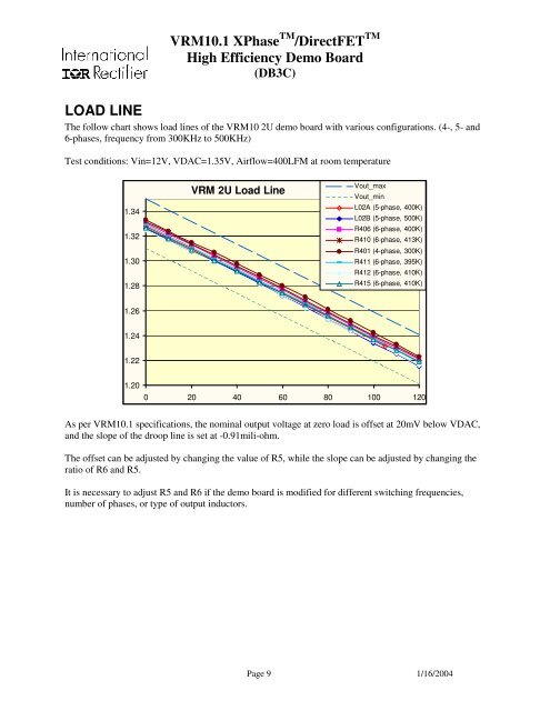
LOAD LINE<br />
The follow chart shows load lines of the VRM10 2U demo board with various configurations. (4-, 5- and<br />
6-phases, frequency from 300KHz to 500KHz)<br />
Test conditions: Vin=12V, VDAC=1.35V, Airflow=400LFM at room temperature<br />
1.34<br />
1.32<br />
1.30<br />
1.28<br />
VRM 2U Load Line<br />
Vout_max<br />
Vout_min<br />
L02A (5-phase, 400K)<br />
L02B (5-phase, 500K)<br />
R406 (6-phase, 400K)<br />
R410 (6-phase, 413K)<br />
R401 (4-phase, 300K)<br />
R411 (6-phase, 395K)<br />
R412 (6-phase, 410K)<br />
R415 (6-phase, 410K)<br />
1.26<br />
1.24<br />
1.22<br />
1.20<br />
0 20 40 60 80 100 120<br />
As per <strong>VRM10.1</strong> specifications, the nominal output voltage at zero load is offset at 20mV below VDAC,<br />
and the slope of the droop line is set at -0.91mili-ohm.<br />
The offset can be adjusted by changing the value of R5, while the slope can be adjusted by changing the<br />
ratio of R6 and R5.<br />
It is necessary to adjust R5 and R6 if the demo board is modified for different switching frequencies,<br />
number of phases, or type of output inductors.<br />
Page 9 1/16/2004


