Instrument Ball Valves, 40 Series (MS-01-60, R7)
Instrument Ball Valves, 40 Series (MS-01-60, R7)
Instrument Ball Valves, 40 Series (MS-01-60, R7)

Create successful ePaper yourself
Turn your PDF publications into a flip-book with our unique Google optimized e-Paper software.
www.swagelok.com<br />
<strong>Instrument</strong> <strong>Ball</strong> <strong>Valves</strong><br />
<strong>40</strong> <strong>Series</strong><br />
■ On-off, switching, and crossover flow paths<br />
■ Working pressures up to 3000 psig (206 bar)<br />
■ Temperatures from 50 to 150°F (10 to 65°C)<br />
■ Low-temperature service option from –65 to 150°F (–53 to 65°C)<br />
■ 1/16 to 3/4 in. and 3 to 12 mm end connections<br />
■ Virtually no dead space
2 <strong>40</strong> <strong>Series</strong> <strong>Ball</strong> <strong>Valves</strong><br />
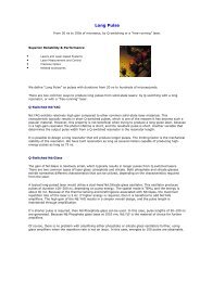
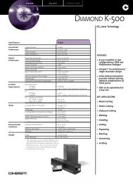
Features<br />
Directional handle<br />
indicates position<br />
of orifice.<br />
Top-loaded design<br />
allows adjustment with<br />
the valve in-line.<br />
Panel nut<br />
secures valve to<br />
panel or actuator.<br />
End connections<br />
include gaugeable➀<br />
Swagelok ® tube fittings and<br />
a variety of others.<br />
Capsule seat packing<br />
■ does not require system<br />
pressure to make a seal<br />
■ allows bidirectional flow<br />
■ has virtually no dead space<br />
■ is easily cleaned and purged<br />
■ is available in optional materials<br />
for system compatibility.<br />
One-piece body<br />
eliminates multiple<br />
seal points.<br />
➀ Stainless steel and alloy <strong>40</strong>0<br />
Swagelok tube fittings are gaugeable.<br />
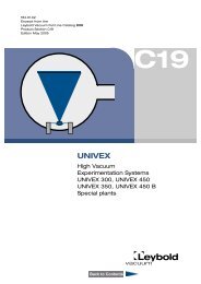
Materials of Construction<br />
2<br />
41, 42,<br />
2<br />
44, 45<br />
43 series<br />
series 3<br />
4<br />
8<br />
9<br />
5<br />
6 9<br />
8<br />
7<br />
10<br />
12<br />
11<br />
1<br />
One-piece ball stem<br />
ensures alignment of<br />
ball and orifice.<br />
Lubricant ➃ Valve Body Materials<br />
41, 42, 43 series—silicone-based; 44, 45 series—silicone- and fluorinated-based<br />
Stainless Steel Brass Alloy <strong>40</strong>0<br />
Component<br />
Material Grade/ASTM Specification<br />
1 Handle<br />
Nylon with brass insert<br />
Set screw<br />
S17<strong>40</strong>0 SS/A564<br />
2 Packing bolt➀ Powdered metal 300 series SS/<br />
B783 or 316 SS/A276, A479<br />
Brass CDA 3<strong>60</strong>/B16 Alloy R-<strong>40</strong>5/B164<br />
41, 42, 45 series—<br />
3 Upper gland 316 SS/A2<strong>40</strong><br />
brass 2<strong>60</strong>/B36;<br />
43, 44 series—<br />
316 SS/A2<strong>40</strong><br />
Alloy <strong>40</strong>0/B127<br />
4 Bushing PTFE/D1710<br />
5 Lower gland<br />
Powdered metal<br />
300 series SS/B783<br />
Brass CDA 3<strong>60</strong>/B16 Alloy <strong>40</strong>0/B164<br />
6 Upper packing PTFE/D1710<br />
7 <strong>Ball</strong> stem 316 SS/A276 and A479 Brass CDA 3<strong>60</strong>/B16 ➁ Alloy R-<strong>40</strong>5/B164<br />
8 Side rings Fluorocarbon-coated<br />
Fluorocarbon-coated<br />
powdered metal<br />
brass powdered metal ➁<br />
9a Side discs 300 series SS/B783<br />
Fluorocarbon-coated<br />
alloy <strong>40</strong>0 powdered metal<br />
10a Lower packing<br />
PTFE/D1710<br />
11a Panel nut<br />
Powdered metal<br />
Powdered metal<br />
Brass CDA 3<strong>60</strong>/B16<br />
300 series SS/B783<br />
300 series SS/B783<br />
12a Body ➂ 316 SS/A276 and A479 Brass CDA 3<strong>60</strong>/B16 Alloy <strong>40</strong>0/B164<br />
Wetted components listed in italics.<br />
➀ Molybdenum disulfide with hydrocarbon binder coating.<br />
➁ 4-way, 5-way, 6-way, and 7-way valves contain stainless steel stem, rings, and discs.<br />
➂ Bodies with VCO ® end connections have fluorocarbon FKM O-rings.<br />
➃ For valves assembled without lubrication, see Options, page 8.<br />
Important Information about Packed <strong>Valves</strong><br />
■ Packing adjustment may be required<br />
during the valve’s service life.<br />
Warning: Failure to periodically<br />
inspect and maintain valve packing<br />
may result in leakage. Service<br />
instructions are shipped with each<br />
<strong>40</strong> series ball valve.<br />
■ Swagelok ball valves are designed to<br />
be used in a fully open or fully closed<br />
position.<br />
■ <strong>Valves</strong> that have not been cycled for a<br />
period of time may have a higher<br />
initial actuation torque.<br />
■ Packing in <strong>40</strong> series ball valves is<br />
factory adjusted for service at 1000 psig<br />
and 70°F. Packing must be readjusted<br />
for service at other than test pressure.<br />
■ <strong>Valves</strong> exposed to dynamic temperature<br />
conditions before installation may lose<br />
their initial packing load. Packing<br />
adjustment may be needed.<br />
■ 43 series ball valves require an<br />
adapter to adjust the packing bolt.<br />
Ordering number: <strong>MS</strong>-WK-43<br />
For all other <strong>40</strong> series ball valves,<br />
packing adjustments can be made<br />
with standard wrenches.<br />
Testing<br />
Every <strong>40</strong> series ball valve is adjusted for<br />
factory testing at 1000 psig (69 bar) with<br />
nitrogen or at its maximum rated<br />
pressure if less than 1000 psig (69 bar).<br />
Seat tests have a maximum allowable<br />
leak rate of 0.1 std cm 3 /min.<br />
Cleaning and Packaging<br />
Every <strong>40</strong> series ball valve is cleaned<br />
and packaged in accordance with<br />
Swagelok standard cleaning and<br />
packaging specification (SC-10),<br />
<strong>MS</strong>-06-62.
<strong>40</strong> <strong>Series</strong> <strong>Ball</strong> <strong>Valves</strong> 3<br />
On-Off (2-Way) <strong>Valves</strong><br />
Flow Data at 70°F (20°C)<br />
Straight-<br />
Pattern<br />
Valve<br />
Pressure-Temperature<br />
Ratings<br />
➀ Pressure ratings for valves with<br />
Swagelok tube fitting ends may be<br />
lower. See Swagelok Tubing Data,<br />
<strong>MS</strong>-<strong>01</strong>-107.<br />
Ordering Information<br />
and Dimensions<br />
Add SS for 316 stainless<br />
steel, B for brass, or M for<br />
alloy <strong>40</strong>0 to the basic ordering<br />
number.<br />
Example: SS-43S4<br />
Dimensions are for reference<br />
only and are subject to<br />
change.<br />
H<br />
panel<br />
hole<br />
F<br />
B<br />
B 1<br />
A<br />
➀ 1/8 in. (3.2 mm) minimum panel<br />
thickness.<br />
W<br />
Angle-<br />
Pattern<br />
Valve<br />
On Off On Off<br />
G<br />
max panel<br />
thickness ➀<br />
Angle-Pattern <strong>Valves</strong><br />
Add -A to the ordering number<br />
of a valve with the C<br />
dimension listed.<br />
Example: SS-43S4-A<br />
C<br />
Dimensions shown with Swagelok<br />
tube fitting nuts finger-tight.<br />
D<br />
E<br />
J<br />
Valve <strong>Series</strong><br />
Temperature<br />
Rating<br />
°F (°C)<br />
Pressure<br />
Rating ➀<br />
psig (bar)<br />
41, 42, 41-A, 42-A, 43-A 2500 (172)<br />
43 50 to 150 3000 (206)<br />
44, 45 (10 to 65) 2500 (172)<br />
44-A, 45-A 1500 (103)<br />
Pressure Drop to Atmosphere (∆p), psi<br />
10 50 100 10 50 100<br />
C Air Flow, std ft 3 v<br />
/min Water Flow, U.S. gal/min<br />
0.10 1.1 3.0 5.3 0.3 0.7 1.0<br />
0.20 2.3 6.0 11 0.6 1.4 2.0<br />
0.50 5.6 15 27 1.6 3.5 5.0<br />
0.<strong>60</strong> 6.8 18 32 1.9 4.2 6.0<br />
0.90 10 27 48 2.8 6.4 9.0<br />
1.2 14 36 64 3.8 8.5 12<br />
1.5 17 45 80 4.7<br />
15<br />
11<br />
1.6 18 48 85 5.0 16<br />
2.4 27 72 120 7.6 17 24<br />
2.6 29 78 1<strong>40</strong> 8.2 18 26<br />
3.0 34 90 1<strong>60</strong> 9.5 21 30<br />
6.0 68 180 320 19 42 <strong>60</strong><br />
6.3 71<br />
330<br />
63<br />
190<br />
20 45<br />
6.4 72 3<strong>40</strong> 64<br />
12 130 3<strong>60</strong> 6<strong>40</strong> 38 85 120<br />
For angle-pattern valve flow data, see Flow Data, page 4.<br />
Orifice<br />
End Connections Basic<br />
Ordering C v<br />
Dimensions, in. (mm)<br />
Inlet/Outlet Size Number C v Angle in. mm A B B 1 C D E F G H J W<br />
1/16 -41S1 0.1 — 0.052 1.3 1.68<br />
(42.7)<br />
0.84 (21.3) —<br />
1/8 -41S2 0.2 0.15 0.093 2.4 2.<strong>01</strong> 1.<strong>01</strong> (25.7)<br />
0.97 0.34 0.28 1.12 1/4 19/32 1.36 0.58<br />
(51.1)<br />
(24.6) (8.6) (7.1) (28.4) (6.4) (15.1) (34.5) (14.7)<br />
-42S4 0.6 0.35 0.125 3.2 2.21 1.10 (27.9)<br />
1.07<br />
(56.1)<br />
(27.2)<br />
Fractional<br />
1/4<br />
Swagelok<br />
-43S4 1.4 0.90<br />
2.36<br />
1.18 (30.0)<br />
1.17<br />
(59.9)<br />
(29.7)<br />
tube fittings<br />
0.187 4.8<br />
0.44 0.38 1.53 3/16 25/32 1.56 0.78<br />
(11.2) (9.7) (38.9) (4.8) (19.8) (39.6) (19.8)<br />
-43S6 1.5 0.90<br />
2.58<br />
1.29 (32.8)<br />
1.29<br />
(65.5)<br />
(32.8)<br />
3/8<br />
-44S6 6.0 2.00 0.281 7.1 3.05 1.52 (38.6)<br />
1.43<br />
0.56 (14.2)<br />
2.00 1 1/8 2.07 1.12<br />
(77.5)<br />
(36.3)<br />
(50.8) (28.6) (52.6) (28.4)<br />
3/8<br />
1/2 -45S8 12 4.<strong>60</strong><br />
(9.5)<br />
0.<strong>40</strong>6 10.3 3.92 1.96 (49.8)<br />
1.74<br />
0.69 (17.5)<br />
3.00 1 1/2 2.43 1.50<br />
3/4 -45S12 6.4 3.80<br />
(99.6)<br />
(44.2)<br />
(76.2) (38.1) (61.7) (38.1)<br />
3 mm -41S3MM 0.2 0.15 0.093 2.4 2.<strong>01</strong> 1.<strong>01</strong> (25.7)<br />
0.97<br />
(51.1)<br />
(24.6) 0.34 0.28 1.12 1/4 19/32 1.36 0.58<br />
0.35<br />
1.07 (8.6) (7.1) (28.4) (6.4) (15.1) (34.5) (14.7)<br />
-42S6MM 0.6 0.125 3.2 2.21 1.10 (27.9)<br />
(56.1)<br />
(27.2)<br />
6 mm<br />
Metric<br />
-43S6MM 1.4 0.90<br />
2.39<br />
1.20 (30.5)<br />
1.17<br />
(<strong>60</strong>.7)<br />
(29.7)<br />
Swagelok<br />
0.187 4.8<br />
0.44 0.38 1.53 3/16 25/32 1.56 0.78<br />
tube fittings<br />
(11.2) (9.7) (38.9) (4.8) (19.8) (39.6) (19.8)<br />
8 mm -43S8MM 1.5 0.90<br />
2.46<br />
1.23 (31.2)<br />
1.20<br />
(62.5)<br />
(30.5)<br />
10 mm -44S10MM 6.0 2.00 0.281 7.1 3.07 1.53 (38.9)<br />
1.43<br />
0.56 (14.2)<br />
2.00 1 1/8 2.07 1.12<br />
(78.0)<br />
(36.9)<br />
(50.8) 3/8 (28.6) (52.6) (28.4)<br />
12 mm -45S12MM 12 4.<strong>60</strong><br />
1.74<br />
(9.5)<br />
0.<strong>40</strong>6 10.3 3.92 1.96 (49.8) 0.69 (17.5)<br />
3.00 1 1/2 2.43 1.50<br />
(99.6)<br />
(44.2)<br />
(76.2) (38.1) (61.7) (38.1)<br />
-42F2 0.5 0.30 0.125 3.2 1.62 0.81 (20.6)<br />
0.34 0.28 1.12 1/4 19/32 1.36 0.58<br />
(41.1)<br />
(8.6) (7.1) (28.4) (6.4) (15.1) (34.5) (14.7)<br />
1/8<br />
-43F2 1.2 0.70<br />
2.00<br />
1.00 (25.4)<br />
(50.8)<br />
0.187 4.8<br />
0.44 0.38 1.53 3/16 25/32 1.56 0.78<br />
(11.2) (9.7) (38.9) (4.8) (19.8) (39.6) (19.8)<br />
Female -43F4 0.9 0.75<br />
2.06<br />
1.03 (26.2)<br />
NPT 1/4<br />
(52.3)<br />
-44F4 3.0 1.70<br />
0.281 7.1 2.50 1.25 (31.8) 0.56 (14.2)<br />
2.00 1 1/8 2.07 1.12<br />
3/8 -44F6 2.6 1.50<br />
(63.5)<br />
(50.8) 3/8 (28.6) (52.6) (28.4)<br />
(9.5)<br />
1/2 -45F8 6.3 3.50 0.<strong>40</strong>6 10.3 3.12 1.56 (39.6) 0.69 (17.5)<br />
3.00 1 1/2 2.43 1.50<br />
(79.2)<br />
(76.2) (38.1) (61.7) (38.1)<br />
Male NPT 1/4 -43M4 1.2 0.75 0.187 4.8 2.00 1.00 (25.4)<br />
1.03 0.44 0.38 1.53 3/16 25/32 1.56 0.78<br />
(50.8)<br />
(26.2) (11.2) (9.7) (38.9) (4.8) (19.8) (39.6) (19.8)<br />
Male NPT/<br />
Swagelok 1/4 -43M4-S4 1.6 0.75 0.187 4.8 2.20 1.00 1.20 1.03 0.44 0.38 1.53 3/16 25/32 1.56 0.78<br />
(55.9) (25.4) (30.5) (26.2) (11.2) (9.7) (38.9) (4.8) (19.8) (39.6) (19.8)<br />
tube fitting<br />
1/4 -43F4RT 0.9 — 0.187 4.8 2.06 1.03 (26.2) —<br />
0.44 0.38 1.53 3/16 25/32 1.56 0.78<br />
(52.3)<br />
(11.2) (9.7) (38.9) (4.8) (19.8) (39.6) (19.8)<br />
Female ISO<br />
tapered<br />
3/8 -44F6RT 2.6 — 0.281 7.1 2.50 1.25 (31.8) — 0.56 (14.2)<br />
2.00 1 1/8 2.07 1.12<br />
(63.5)<br />
(50.8) 3/8 (28.6) (52.6) (28.4)<br />
1/2 -45F8RT 6.3<br />
(9.5)<br />
— 0.<strong>40</strong>6 10.3 3.12 1.56 (39.6) — 0.69 (17.5)<br />
3.00 1 1/2 2.43 1.50<br />
(79.2)<br />
(76.2) (38.1) (61.7) (38.1)<br />
VCO fittings 1/4<br />
-42VCO4 0.6 0.35 0.125 3.2 1.75 0.88 (22.4)<br />
1.12 19/32 1.36<br />
(44.4)<br />
0.94 0.44 0.38 (28.4) 3/16 (15.1) (34.5) 0.78<br />
-43VCO4 2.4<br />
(23.9) (11.2) (9.7) (4.8)<br />
(19.8)<br />
0.90 0.187 4.8 1.88 0.94 (23.9)<br />
1.53 25/32 1.56<br />
(47.8)<br />
(38.9) (19.8) (39.6)<br />
-42VCR4 0.6 0.35 0.125 3.2 1.06 (26.9)<br />
1.12 19/32 1.36<br />
1/4<br />
2.13<br />
1.09 0.44 0.38 (28.4) 3/16 (15.1) (34.5) 0.78<br />
(54.1)<br />
(27.7) (11.2) (9.7) (4.8)<br />
(19.8)<br />
-43VCR4 2.4 0.90 0.187 4.8 1.03<br />
Male VCR ®<br />
(26.2)<br />
1.53 25/32 1.56<br />
(38.9) (19.8) (39.6)<br />
fittings<br />
-44VCR8 6.0 — 0.281 7.1 2.88 1.44 (36.6) — 0.56 (14.2)<br />
2.00 1 1/8 2.07<br />
(73.2)<br />
(50.8)<br />
1/2<br />
3/8 (28.6) (52.6) 1.50<br />
(9.5)<br />
(38.1)<br />
-45VCR8 12 — 0.<strong>40</strong>6 10.3 3.12 1.56 (39.6) — 0.69 (17.5)<br />
3.00 1 1/2 2.43<br />
(79.2)<br />
(76.2) (38.1) (61.7)
4 <strong>40</strong> <strong>Series</strong> <strong>Ball</strong> <strong>Valves</strong><br />
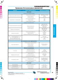
Switching (3-Way, 5-Way, and 7-Way) <strong>Valves</strong><br />
3-Way Valve 5-Way Valve 7-Way Valve<br />
Features<br />
■ Unique, top-loaded capsule packing allows reliable<br />
switching.<br />
■ Flow can be switched from a single inlet to multiple outlets<br />
or from multiple inlets to a common outlet.<br />
■ 3-way valve has a center-off position.<br />
■ 5- and 7-way 43 series valves have a spring-loaded detent<br />
for exact port positioning.<br />
■ Detent handle components:<br />
Handle: nylon with brass insert<br />
Set screw: S17<strong>40</strong>0 stainless steel<br />
Pins, detent plate: nickel-plated steel<br />
Springs: steel/ASTM A228<br />
Pressure-Temperature Ratings<br />
Valve <strong>Series</strong> Flow Pattern<br />
Temperature<br />
Rating<br />
°F (°C)<br />
Pressure<br />
Rating ➀<br />
psig (bar)<br />
41X, 42X, 43X 2500 (172)<br />
3-way<br />
44X, 45X 1500 (103)<br />
50 to 150<br />
43Z 2500 (172)<br />
5-way (10 to 65)<br />
45Z 1500 (103)<br />
43Z6 7-way 500 (34.4)<br />
➀ Pressure ratings for valves with Swagelok tube fitting ends<br />
may be lower. See Swagelok Tubing Data, <strong>MS</strong>-<strong>01</strong>-107.<br />
Flow Data at 70°F (20°C)<br />
Pressure Drop to Atmosphere (∆p) psi<br />
10 50 100 10 50 100<br />
C v<br />
Air Flow, std ft 3 /min<br />
Water Flow, U.S. gal/min<br />
2-Way Angle Pattern and 3-Way <strong>Valves</strong><br />
0.08 0.9 2.4 4.3 0.3 0.6 0.8<br />
0.15 1.7 4.5 8.0 0.4 1.0 1.5<br />
0.30 3.4 9.0 16 0.9 2.1 3.0<br />
0.35 4.0 10 19 1.1 2.4 3.5<br />
0.75 8.5 22 <strong>40</strong> 2.3 5.3 7.5<br />
0.80 9.0 24 42 2.5 5.6 8.0<br />
0.90 10 27 48 2.8 6.3 9.0<br />
1.5 17 45 80 4.7 11 15<br />
1.7 19 51 90 5.3 12 17<br />
2.0 22 <strong>60</strong> 100 6.3 14 20<br />
3.5 39 100 180 11 25 35<br />
3.8 43 110 200 12 27 38<br />
4.6 52 1<strong>40</strong> 2<strong>40</strong> 15 33 46<br />
0.07 0.8 2.1<br />
5-Way <strong>Valves</strong><br />
3.7 0.2 0.5 0.7<br />
3.5 39 100 180 11 25 35<br />
7-Way <strong>Valves</strong><br />
0.05 0.6 1.5 2.6 0.1 0.3 0.5<br />
0.07 0.8 2.1 3.7 0.2 0.5 0.7
<strong>40</strong> <strong>Series</strong> <strong>Ball</strong> <strong>Valves</strong> 5<br />
Ordering Information and Dimensions<br />
Add SS for 316 stainless steel, B for brass, or M for alloy <strong>40</strong>0 to the basic ordering number.<br />
Example: SS-43XS4<br />
Dimensions are for reference only and are subject to change.<br />
3-Way Valve<br />
F<br />
5-Way Valve<br />
F<br />
7-Way Valve<br />
F<br />
J<br />
G max panel<br />
D<br />
H<br />
panel<br />
hole<br />
H<br />
panel<br />
hole<br />
G<br />
max panel<br />
thickness ➀<br />
D<br />
J<br />
H<br />
panel<br />
hole<br />
G<br />
max panel<br />
thickness ➀<br />
D<br />
J<br />
thickness ➀ B<br />
C<br />
C<br />
C<br />
C<br />
A<br />
W<br />
➀ 1/8 in. (3.2 mm) minimum panel thickness.<br />
B<br />
A<br />
B<br />
A<br />
End Connections Basic<br />
Orifice Dimensions, in. (mm)<br />
Ordering<br />
Inlet/Outlet Size Number C v in. mm A B C D F G H J W<br />
3-Way <strong>Valves</strong><br />
1/16 -41XS1 0.08 0.052 1.3 1.68 (42.7) 0.84 (21.3) 0.81 (20.6)<br />
1/8 -41XS2 0.15 0.093 2.4 2.<strong>01</strong> (51.1) 1.<strong>01</strong> (25.7) 0.97 (24.6) 0.34 (8.6) 1.13 (28.7) 1/4 (6.4) 19/32 (15.0) 1.36 (34.5) 0.58 (14.7)<br />
-42XS4 0.35 0.125 3.2 2.21 (56.1) 1.10 (27.9) 1.07 (27.2)<br />
Fractional 1/4<br />
Swagelok<br />
-43XS4 0.90 0.187 4.8 2.39 (<strong>60</strong>.7) 1.20 (30.5) 1.17 (29.7) 0.44 (11.2) 1.53 (38.9) 3/16 (4.8) 25/32 (19.8) 1.56 (39.6) 0.78 (19.8)<br />
tube fittings<br />
3/8 -44XS6 2.0 0.281 7.1 2.89 (73.4) 1.45 (36.8) 1.43 (36.3) 0.56 (14.2) 2.00 (50.8)<br />
1 1/8 (28.7) 2.07 (52.6) 1.12 (28.4)<br />
1/2 -45XS8 4.6<br />
3/8 (9.7)<br />
0.<strong>40</strong>6 10.3 3.48 (88.4) 1.74 (44.2) 0.69 (17.5) 3.00 (76.2)<br />
3/4 -45XS12 3.8<br />
1 1/2 (38.1) 2.43 (61.7) 1.50 (38.1)<br />
3 mm -41XS3MM 0.15 0.093 2.4 2.<strong>01</strong> (51.1) 1.<strong>01</strong> (25.7) 0.97 (24.6)<br />
0.34 (8.6) 1.13 (28.7) 1/4 (6.4) 19/32 (15.0) 1.36 (34.5) 0.58 (14.7)<br />
-42XS6MM 0.35 0.125 3.2 2.21 (56.1) 1.10 (27.9) 1.07 (27.2)<br />
6 mm<br />
Metric<br />
-43XS6MM 0.90<br />
2.39 (<strong>60</strong>.7) 1.20 (30.5) 1.17 (29.7)<br />
Swagelok<br />
0.187 4.8<br />
0.44 (11.2) 1.53 (38.9) 3/16 (4.8) 25/32 (19.8) 1.56 (39.6) 0.78 (19.8)<br />
tube fittings 8 mm -43XS8MM 0.80 2.46 (62.5) 1.23 (31.2) 1.20 (30.5)<br />
10 mm -44XS10MM 2.0 0.281 7.1 2.89 (73.4) 1.45 (36.8) 1.43 (36.3) 0.56 (14.2) 2.00 (50.8)<br />
1 1/8 (28.7) 2.07 (52.6) 1.12 (28.4)<br />
3/8 (9.7)<br />
12 mm -45XS12MM 4.6 0.<strong>40</strong>6 10.3 3.48 (88.4) 1.74 (44.2) 0.69 (17.5) 3.00 (76.2) 1 1/2 (38.1) 2.43 (61.7) 1.50 (38.1)<br />
1/8 -42XF2 0.30 0.125 3.2 1.63 (41.4) 0.81 (20.6) 0.34 (8.6) 1.13 (28.7) 1/4 (6.4) 19/32 (15.0) 1.36 (34.5) 0.58 (14.7)<br />
Female NPT<br />
-43XF4 0.75 0.187 4.8 2.06 (52.3) 1.03 (26.2) 0.44 (11.2) 1.53 (38.9) 3/16 (4.8) 25/32 (19.8) 1.56 (39.6) 0.78 (19.8)<br />
1/4<br />
-44XF4 1.7<br />
0.281 7.1 2.50 (63.5) 1.25 (31.8) 0.56 (14.2) 2.00 (50.8)<br />
1 1/8 (28.7) 2.07 (52.6) 1.12 (28.4)<br />
3/8 -44XF6 1.5<br />
3/8 (9.7)<br />
1/2 -45XF8 3.5 0.<strong>40</strong>6 10.3 3.13 (79.5) 1.56 (39.6) 0.69 (17.5) 3.00 (76.2) 1 1/2 (38.1) 2.43 (61.7) 1.50 (38.1)<br />
Male NPT/<br />
Swagelok 1/4 -43XS4-S4-M4 0.80 0.187 4.8 2.<strong>40</strong> (61.0) 1.20 (30.5) 1.03 (26.2) 0.44 (11.2) 1.53 (38.9) 3/16 (4.8) 25/32 (19.8) 1.56 (39.6) 0.78 (19.8)<br />
tube fittings<br />
1/4 -43XF4RT 0.75 0.187 4.8 2.06 (52.3) 1.03 (26.2) 0.44 (11.2) 1.53 (38.9) 3/16 (4.8) 25/32 (19.8) 1.56 (39.6) 0.78 (19.8)<br />
Female ISO<br />
3/8 -44XF6RT 1.5 0.281 7.1 2.50 (63.5) 1.25 (31.8) 0.56 (14.2) 2.00 (50.8)<br />
1 1/8 (28.7) 2.07 (52.6) 1.12 (28.4)<br />
tapered<br />
3/8 (9.7)<br />
1/2 -45XF8RT 3.5 0.<strong>40</strong>6 10.3 3.13 (79.5) 1.56 (39.6) 0.69 (17.5) 3.00 (76.2) 1 1/2 (38.1) 2.43 (61.7) 1.50 (38.1)<br />
Male VCR<br />
-42XVCR4 0.35 0.125 3.2<br />
1.13 (28.7)<br />
19/32 (15.0) 1.36 (34.5)<br />
1/4<br />
2.13 (54.1) 1.06 (26.9) 1.09 (27.7) 0.44 (11.2)<br />
3/16 (4.8)<br />
fittings<br />
-43XVCR4 0.90 0.187 4.8 1.53 (38.9)<br />
25/32 (19.8) 1.56 (39.6)<br />
0.78 (19.8)<br />
Female<br />
Swagelok<br />
tube fittings<br />
Female NPT<br />
Female<br />
Swagelok<br />
tube fittings<br />
5-Way <strong>Valves</strong><br />
1/8 -43ZFS2➀ 0.07 0.062 1.6 1.94 (49.3) 0.97 (24.6) 0.44 (11.2) 1.53 (38.9) 5/32 (4.1) 29/32 (23.1) 1.69 (42.9) —<br />
1/8 -43ZF2 ➀ 0.07 0.062 1.6 1.55 (39.4) 0.78 (19.8) 0.88 (22.4) 0.44 (11.2) 1.53 (38.9) 5/32 (4.1) 29/32 (23.1) 1.69 (42.9) —<br />
1/2 -45ZF8-ND ➁ 3.5 0.<strong>40</strong>6 10.3 3.13 (79.5) 1.56 (39.6) 0.69 (17.5) 3.00 (76.2) 3/8 (9.7) 1 1/2 (38.1) 2.43 (61.7) —<br />
1/16 -43Z6FS1 0.05 0.052 1.3<br />
1/8 -43Z6FS2 0.07 0.062 1.6<br />
7-Way <strong>Valves</strong><br />
1.94 (49.3) 0.97 (24.6) 0.44 (11.2) 1.53 (38.9) 5/32 (4.1) 29/32 (23.1) 1.69 (42.9) —<br />
Dimensions shown with Swagelok tube fitting nuts finger-tight.<br />
➀ Cross-port flow may occur during switching. If cross-port flow is unacceptable, specify a 0.049 in. ball orifice. Example: SS-43ZF2-049<br />
➁ Cross-port flow may occur during switching. If cross-port flow is unacceptable, specify a 0.093 in. ball orifice. Example: SS-45ZF8-ND-093
6 <strong>40</strong> <strong>Series</strong> <strong>Ball</strong> <strong>Valves</strong><br />
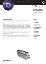
Crossover (4-Way and 6-Way) <strong>Valves</strong><br />
4-Way Valve<br />
6-Way Valve<br />
Features<br />
■ Capsule packing allows crossover of two or three streams.<br />
■ Machined stops provide positive port positioning.<br />
■ Stop plate material: aluminum/ASTM B209 or B211.<br />
Pressure-Temperature Ratings<br />
Valve<br />
<strong>Series</strong><br />
Flow<br />
Pattern<br />
Temperature<br />
Rating<br />
°F (°C)<br />
Working<br />
Pressure<br />
psig (bar)<br />
43Y6 2500 (172)<br />
4-way 50 to 150<br />
45Y6<br />
1500 (103)<br />
(10 to 65)<br />
43Y6 6-way<br />
1500 (34.4)<br />
Flow Data at 70°F (20°C)<br />
Pressure Drop to Atmosphere (∆p), psi<br />
10 50 100 10 50 100<br />
C v<br />
Air Flow, std ft 3 /min<br />
Water Flow, U.S. gal/min<br />
4-Way <strong>Valves</strong><br />
0.06 0.7 1.8 3.2<br />
0.4 0.6<br />
0.2<br />
0.08 0.9 2.4 4.2 0.5 0.8<br />
1.6 18 48 85 5.0 11 16<br />
6-Way <strong>Valves</strong><br />
0.06 0.7 1.8 3.2<br />
0.4 0.6<br />
0.2<br />
0.08 0.9 2.4 4.2 0.5 0.8<br />
Ordering Information and Dimensions<br />
Dimensions are for reference only and<br />
are subject to change.<br />
Add SS for 316 stainless steel, B for<br />
brass, or M for alloy <strong>40</strong>0 to the basic<br />
ordering number.<br />
Example: SS-43YF2<br />
4-Way Valve<br />
H<br />
panel<br />
hole<br />
6-Way Valve<br />
F<br />
F<br />
B<br />
A<br />
G<br />
max panel<br />
thickness ➀<br />
D<br />
E<br />
J<br />
End Connection Basic<br />
Orifice Dimensions, in. (mm)<br />
Ordering<br />
Type Size Number C v in. mm A B D E F G H J<br />
4-Way <strong>Valves</strong><br />
Female<br />
Swagelok<br />
tube fitting<br />
Female<br />
NPT<br />
Female<br />
Swagelok<br />
tube fitting<br />
1/16 -43YFS1➀ 0.06 0.052 1.3<br />
1.55<br />
(39.4)<br />
1/8 -43YFS2➀<br />
1.95<br />
(49.5)<br />
0.08 0.062 1.6<br />
1/8 -43YF2➀ 1.55<br />
(39.4)<br />
1/2 -45YF8➁ 1.6 0.281 7.1<br />
3.13<br />
(79.5)<br />
6-Way <strong>Valves</strong><br />
1/16 -43Y6FS1 0.06 0.052 1.3<br />
1.95<br />
(49.5)<br />
1/8 -43Y6FS2 0.08 0.062 1.6<br />
0.78<br />
(19.8)<br />
0.98<br />
(24.9)<br />
0.78<br />
(19.8)<br />
1.56<br />
(39.6)<br />
0.97<br />
(24.6)<br />
0.44<br />
(11.2)<br />
0.44<br />
(11.2)<br />
0.69<br />
(17.5)<br />
0.44<br />
(11.2)<br />
0.44<br />
(11.2)<br />
0.44<br />
(11.2)<br />
0.69<br />
(17.5)<br />
0.44<br />
(11.2)<br />
1.53<br />
(38.9)<br />
1.53<br />
(38.9)<br />
3.00<br />
(76.2)<br />
1.53<br />
(38.9)<br />
➀ Cross-port flow may occur during switching. If cross-port flow is unacceptable, specify a 0.049 in. ball<br />
orifice. Example: SS-43YFS2-049<br />
➁ Cross-port flow may occur during switching. If cross-port flow is unacceptable, specify a 0.093 in. ball<br />
orifice. Example: SS-45YF8-093<br />
3/16<br />
(4.8)<br />
3/16<br />
(4.8)<br />
3/8<br />
(9.7)<br />
3/16<br />
(4.8)<br />
29/32<br />
(23.1)<br />
29/32<br />
(23.1)<br />
1 1/2<br />
(38.1)<br />
29/32<br />
(23.1)<br />
1.68<br />
(42.7)<br />
1.69<br />
(42.9)<br />
2.43<br />
(61.7)<br />
1.68<br />
(42.7)<br />
H<br />
panel<br />
hole<br />
G<br />
max panel<br />
thickness ➀<br />
J<br />
D<br />
E<br />
B<br />
A<br />
➀ 1/8 in. (3.2 mm) minimum panel thickness.
<strong>40</strong> <strong>Series</strong> <strong>Ball</strong> <strong>Valves</strong> 7<br />
Pneumatic Actuators<br />
Swagelok rack and pinion pneumatic<br />
actuators are compact, lightweight, easily<br />
mountable, and can be operated with<br />
standard shop air. For technical data,<br />
including pressure-temperature ratings<br />
and materials of construction, see the<br />
Rack and Pinion Pneumatic Actuators for<br />
Swagelok <strong>Ball</strong> <strong>Valves</strong> catalog, <strong>MS</strong>-06-87.<br />
1/8 in.<br />
NPT<br />
➀ S = spring return<br />
D = double acting<br />
4 mounting<br />
holes 0.34<br />
(8.6) dia<br />
O (S)➀<br />
N (D)➀<br />
B<br />
M<br />
K L D<br />
C<br />
A<br />
Q<br />
G<br />
J<br />
E<br />
F<br />
H<br />
1/8 in.<br />
NPT<br />
Dimensions<br />
Valve <strong>Series</strong><br />
41, 41-A, 41X,<br />
42, 42-A, 42X<br />
43, 43-A,<br />
43X, 43Y<br />
43, 43-A,<br />
43X, 43Y<br />
44, 44-A, 44X<br />
45, 45-A,<br />
45X, 45Y<br />
Actuator<br />
Model<br />
-131<br />
-151<br />
-133<br />
-153<br />
Dimensions, in. (mm)<br />
A B C D E F G H J K L M N O Q<br />
2.81<br />
(71.4)<br />
2.91<br />
(73.9)<br />
0.34<br />
(8.6)<br />
3.72<br />
(94.5)<br />
4.13<br />
(104) 0.48<br />
4.25<br />
(108)<br />
2.00<br />
(50.8)<br />
1.75<br />
(44.5)<br />
3.04<br />
(77.2)<br />
1.73<br />
(43.9)<br />
1.31<br />
(33.3)<br />
0.<strong>60</strong><br />
(15.2)<br />
0.52<br />
(13.2)<br />
0.31<br />
(7.9)<br />
1.46<br />
(37.1)<br />
1.25<br />
(31.8)<br />
4.09<br />
(104)<br />
4.91<br />
(125)<br />
1.80<br />
(45.7)<br />
2.30<br />
(58.4)<br />
2.00<br />
(50.8)<br />
2.31<br />
(58.7)<br />
4.07<br />
(103)<br />
2.32<br />
(58.9)<br />
1.75<br />
(44.5)<br />
0.75<br />
(19.1)<br />
0.81<br />
(20.6)<br />
0.44<br />
(11.2)<br />
2.16<br />
(54.9)<br />
1.56<br />
(39.6)<br />
5.89<br />
(150)<br />
7.86<br />
(200) 2.56<br />
(12.2) 2.19<br />
(65.0)<br />
(55.6)<br />
Actuator Pressure at Maximum System Pressure<br />
Required pressures based on valve performance using<br />
pressurized air or nitrogen.<br />
Actuator<br />
Model<br />
-131<br />
(90°)<br />
-151<br />
(180°)<br />
-133<br />
(90°)<br />
-153<br />
(180°)<br />
Actuator<br />
Designator<br />
-31<br />
-51<br />
-33<br />
-53<br />
Actuation Modes<br />
Double Acting Spring Return<br />
Valve<br />
Single Dual Single Dual<br />
<strong>Series</strong> Minimum Actuator Pressure, psig (bar)<br />
41, 41-A,<br />
42, 42-A<br />
20 (1.4) 35 (2.5) <strong>60</strong> (4.2) 70 (4.9)<br />
43, 43-A, 43Y 50 (3.5) 80 (5.6) 80 (5.6) —<br />
41X, 42X 20 (1.4) 35 (2.5) <strong>60</strong> (4.2) 70 (4.9)<br />
43X 50 (3.5) 80 (5.6) 70 (4.9) —<br />
43, 43-A, 43Y 20 (1.4) 35 (2.5) 65 (4.5) 75 (5.2)<br />
44, 44-A 25 (1.8) 50 (3.5) 70 (4.9) 90 (6.3)<br />
45, 45-A, 45Y <strong>60</strong> (4.2) 100 (6.9) 90 (6.3) —<br />
43X 20 (1.4) 35 (2.5) 65 (4.5) 70 (4.9)<br />
44X 25 (1.8) 50 (3.5) 70 (4.9) 80 (5.6)<br />
45X <strong>60</strong> (4.2) 100 (6.9) 85 (5.9) —<br />
Other Actuator Options<br />
For Field Assembly or Factory Assembly<br />
■ Electric Actuators<br />
For information, see the Swagelok Electric Actuators—141<br />
and 142 <strong>Series</strong> catalog, <strong>MS</strong>-<strong>01</strong>-35.<br />
■ Solenoid <strong>Valves</strong><br />
For information, see the Swagelok Solenoid <strong>Valves</strong> for<br />
Electropneumatically Actuated <strong>Ball</strong> <strong>Valves</strong> catalog, <strong>MS</strong>-02-41.<br />
■ Limit Switches<br />
indicate actuator position by means of an electrical signal. They<br />
meet a variety of NEMA ratings such as NEMA 4 (weatherproof)<br />
and NEMA 7 (explosion proof). For more information, see the<br />
Swagelok Limit Switches catalog, <strong>MS</strong>-06-39.<br />
■ Position Indicators<br />
provide visual status of a valve.<br />
■ ISO 5211-Compliant Actuator Mounting Bracket Kits<br />
For information, see the Swagelok Actuated <strong>Ball</strong> Valve<br />
Selection Guide, <strong>MS</strong>-02-136.<br />
Ordering Information<br />
Factory-Assembled Actuators<br />
Typical Ordering Number<br />
S S - 4 3 S 4 - 3 1 D<br />
Valve Ordering Number<br />
For dual-mounted assemblies<br />
(two valves mounted to one<br />
actuator), add DM to the<br />
ordering number.<br />
Example: SS-43S4-31DDM<br />
Actuators for Field Assembly<br />
Typical Ordering Number<br />
M S - 1 3 1 - D A<br />
Actuator Model<br />
Determine valve series,<br />
then select actuator model<br />
(see Actuator Pressure table).<br />
Mounting Bracket Kits<br />
Valve <strong>Series</strong> Actuator Model<br />
41, 41-A,<br />
42, 42-A<br />
-131<br />
41X, 42X -151<br />
43, 43-A -131<br />
43X -151<br />
43, 43-A -133<br />
43X -153<br />
43Y<br />
44, 44-A<br />
Actuator Designator<br />
Determine valve series,<br />
then select actuator<br />
model (see Actuator<br />
Pressure table).<br />
Ordering Number<br />
<strong>MS</strong>-MB-41 ➀<br />
<strong>MS</strong>-MB-43<br />
<strong>MS</strong>-MB-43-133<br />
-131 <strong>MS</strong>-MB-43Y<br />
-133<br />
44X -153<br />
45, 45-A -133<br />
45X -153<br />
<strong>MS</strong>-MB-43Y-133<br />
<strong>MS</strong>-MB-44 ➁<br />
<strong>MS</strong>-MB-45<br />
45Y -133 <strong>MS</strong>-MB-45Y<br />
Actuation Mode<br />
D = double acting<br />
C = spring return,<br />
normally closed<br />
O = spring return,<br />
normally open<br />
S = spring return,<br />
3- and 4-way valves<br />
Actuation Mode<br />
DA = double acting<br />
SR = spring return<br />
➀ 42 series valves with<br />
VCO or VCR end<br />
connections mounted to<br />
an actuator are only<br />
available factory<br />
assembled.<br />
➁ 44 series valves with<br />
VCR end connections<br />
require kit<br />
<strong>MS</strong>-MB-44-VCR.
Options<br />
Handles<br />
Factory-Assembled Nylon<br />
Black is standard. For other colors,<br />
add a handle color designator to<br />
the valve ordering number.<br />
Example: SS-43S4-BL<br />
Handle Kits<br />
include handle and set screw.<br />
Valve<br />
<strong>Series</strong><br />
316 Stainless Steel Bar<br />
Add -SH to the valve ordering number.<br />
Example: SS-43S4-SH<br />
Aluminum Bar<br />
Add -BKB to the valve ordering number.<br />
Example: SS-43S4-BKB<br />
Nylon Oval (2- and 3-Way)<br />
Add -K to the valve ordering number.<br />
Example: SS-43S4-K<br />
Nylon oval handles are available factory assembled only.<br />
Nylon Directional<br />
Handle Basic<br />
Ordering Number ➀<br />
Handle Color<br />
Black<br />
Blue<br />
Green<br />
Orange<br />
Red<br />
Yellow<br />
Stainless Steel<br />
Bar Handle<br />
Ordering Number<br />
Designator<br />
-BK<br />
-BL<br />
-GR<br />
-OG<br />
-RD<br />
-YW<br />
Aluminum<br />
Bar Handle<br />
Ordering Number<br />
41, 41-A, 41X, 42, 42-A, 42X BZ-5K-42 SS-5K-42B A-5K-42B-BK<br />
43, 43-A, 43X, 43Y BZ-5K-43 SS-5K-43B A-5K-43B-BK<br />
43Z BZ-5K-43Z — —<br />
44, 44-A, 44X BZ-5K-44 SS-5K-44B A-5K-44B-BK<br />
45, 45-A, 45X, 45Y BZ-5K-45 SS-5K-45B A-5K-45B-BK<br />
➀ For a complete ordering number, add a handle color designator to the basic<br />
ordering number. Example: BZ-5K-42-BK<br />
Vented <strong>Valves</strong><br />
2-Way, Straight-Pattern <strong>Valves</strong><br />
When the valve is closed, the downstream port vents to<br />
atmosphere through a vent hole in the side of the valve body.<br />
2-Way, Angle-Pattern and 3-Way <strong>Valves</strong><br />
When the valve is closed, the bottom port vents to atmosphere<br />
through a vent hole in the side of the valve body.<br />
To order, insert V into the valve ordering number.<br />
Example: SS-43VS4<br />
Pressure rating for vented valves is 500 psig (34.4 bar).<br />
Cross-port flow may occur during actuation. If cross-port flow is unacceptable,<br />
specify a ball orifice of:<br />
■ 0.0<strong>40</strong> in. for 41 and 42 series valves. Example: SS-41VS1-0<strong>40</strong><br />
■ 0.049 in. for 43 and 44 series valves. Example: SS-43VS4-049<br />
■ 0.093 in. for 45 series valves. Example: SS-45VS8-093<br />
Special Cleaning and Packaging (SC-11)<br />
To order <strong>40</strong> series ball valves processed in accordance with<br />
Swagelok Special Cleaning and Packaging (SC-11), <strong>MS</strong>-06-63,<br />
to ensure compliance with product cleanliness requirements<br />
stated in ASTM G93 Level C, add -SC11 to the valve ordering<br />
number.<br />
Example: SS-43S4-SC11<br />
<strong>Valves</strong> Assembled Without Lubrication<br />
<strong>40</strong> series ball valves assembled without lubricant are cleaned<br />
and packaged in accordance with Swagelok Special Cleaning<br />
and Packaging (SC-11), <strong>MS</strong>-06-63, and are adjusted for<br />
factory testing at 200 psig (13.7 bar). <strong>Valves</strong> have a pressure<br />
rating of 200 psig (13.7 bar). Brass valves are assembled with<br />
stainless steel rings, discs, and stem. To order, add -1466 to<br />
the valve ordering number.<br />
Example: SS-43S4-1466<br />
Low-Temperature Service<br />
Live-loaded packing option extends the temperature range to<br />
–65 to 150°F (–53 to 65°C).<br />
For more information, see the Swagelok Live-Loaded <strong>40</strong><br />
<strong>Series</strong> <strong>Ball</strong> <strong>Valves</strong> for Low-Temperature Service catalog,<br />
<strong>MS</strong>-02-109.<br />
Oxygen Service Hazards<br />
For more information about hazards and risks of oxygenenriched<br />
systems, see the Swagelok Oxygen System Safety<br />
technical report, <strong>MS</strong>-06-13.<br />
Sour Gas Service<br />
<strong>40</strong> series ball valves with female pipe ends are available for<br />
sour gas service. Materials for wetted valve components are<br />
selected in accordance with NACE Standard MR<strong>01</strong>75 for<br />
sulfide stress cracking resistant materials. Stem, rings, and<br />
discs are alloy <strong>40</strong>0. To order, add -SG to the valve ordering<br />
number.<br />
Example: SS-43F4-SG<br />
Directional Name Plates<br />
Directional name plates indicate the direction of flow.<br />
A matte surface accepts ink or labels. To order, add -WN1<br />
(blank nameplate) or -WN2 (marked nameplate) to the valve<br />
ordering number.<br />
Example: SS-43S4-WN1<br />
Optional Flow Paths<br />
<strong>40</strong> series ball valves are available with a variety of flow paths<br />
to accommodate many special applications.<br />
For more information, see the Swagelok <strong>40</strong> <strong>Series</strong> <strong>Ball</strong> Valve<br />
Flow Path Options catalog, <strong>MS</strong>-02-30.<br />
Safe Product Selection<br />
When selecting a product, the total system design must<br />
be considered to ensure safe, trouble-free performance.<br />
Function, material compatibility, adequate ratings,<br />
proper installation, operation, and maintenance are the<br />
responsibilities of the system designer and user.<br />
Caution: Do not mix or interchange parts with those of<br />
other manufacturers.<br />
Warranty Information<br />
Swagelok products are backed by The Swagelok Limited<br />
Lifetime Warranty. For a copy, visit swagelok.com or contact<br />
your authorized Swagelok representative.<br />
Swagelok, VCR, VCO—TM Swagelok Company<br />
© 20<strong>01</strong>, 2002, 2005 Swagelok Company<br />
Printed in U.S.A., MI<br />
August 2005, <strong>R7</strong><br />
<strong>MS</strong>-<strong>01</strong>-<strong>60</strong>