integration of cfd and low-order models for combustion ... - IWR
integration of cfd and low-order models for combustion ... - IWR
integration of cfd and low-order models for combustion ... - IWR

You also want an ePaper? Increase the reach of your titles
YUMPU automatically turns print PDFs into web optimized ePapers that Google loves.
0 0.02 0.04 0.06 0.08 0.1 0.12 0.14 0.16 0.18 0.2 0.22<br />
1800<br />
1600<br />
1400<br />
1200<br />
CFD result<br />
with J1 ′<br />
without J1 ′<br />
2.5<br />
2<br />
1000<br />
| T ′ |<br />
800<br />
600<br />
400<br />
| F ′ |<br />
1.5<br />
1<br />
200<br />
0.5<br />
0<br />
0<br />
0 0.02 0.04 0.06 0.08 0.1 0.12 0.14 0.16 0.18 0.2 0.22<br />
250<br />
200<br />
150<br />
CFD result<br />
with J1 ′<br />
without J1 ′<br />
0<br />
100<br />
−50<br />
angle [ T ′ ] deg.<br />
50<br />
0<br />
−50<br />
−100<br />
angle [ F ′ ] deg.<br />
−100<br />
−150<br />
−150<br />
−200<br />
−200<br />
−250<br />
0 0.02 0.04 0.06 0.08 0.1 0.12 0.14 0.16 0.18 0.2 0.22<br />
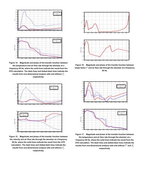
Figure 14. Magnitude <strong>and</strong> phase <strong>of</strong> the transfer function between<br />
the temperature <strong>and</strong> air f<strong>low</strong> rate through the atomizer at a<br />
frequency 50 Hz, where the solid lines indicate the result from the<br />
CFD calculation. The dash lines <strong>and</strong> dotted-dash lines indicate the<br />
results from one-dimensional analysis with <strong>and</strong> without J?1 ,<br />
respectively.<br />
Figure 16.<br />
−250<br />
0 0.02 0.04 0.06 0.08 0.1 0.12 0.14 0.16 0.18 0.2 0.22<br />
Magnitude <strong>and</strong> phase <strong>of</strong> the transfer function between<br />
shape factor F <strong>and</strong> air f<strong>low</strong> rate through the atomizer at a frequency<br />
50 Hz.<br />
450<br />
120<br />
400<br />
CFD result<br />
100<br />
CFD result<br />
with J1 ′<br />
without J1 ′<br />
350<br />
300<br />
with F ′ J2 ′<br />
without F ′ J2 ′<br />
80<br />
250<br />
| T ′ |<br />
200<br />
| u ′ |<br />
60<br />
150<br />
40<br />
100<br />
50<br />
20<br />
0<br />
0 0.02 0.04 0.06 0.08 0.1 0.12 0.14 0.16 0.18 0.2 0.22<br />
0<br />
0 0.02 0.04 0.06 0.08 0.1 0.12 0.14 0.16 0.18 0.2 0.22<br />
200<br />
150<br />
150<br />
CFD result<br />
100<br />
CFD result<br />
with J1 ′<br />
100<br />
with F ′ J2 ′<br />
without F ′ J2 ′<br />
without J1 ′<br />
50<br />
angle [ u ′ ] deg.<br />
50<br />
0<br />
−50<br />
−100<br />
−150<br />
angle [ T ′ ] deg.<br />
0<br />
−50<br />
−100<br />
−150<br />
−200<br />
−250<br />
0 0.02 0.04 0.06 0.08 0.1 0.12 0.14 0.16 0.18 0.2 0.22<br />
Figure 15.<br />
−200<br />
0 0.02 0.04 0.06 0.08 0.1 0.12 0.14 0.16 0.18 0.2 0.22<br />
Magnitude <strong>and</strong> phase <strong>of</strong> the transfer function between<br />
the velocity <strong>and</strong> air f<strong>low</strong> rate through the atomizer at a frequency<br />
50 Hz, where the solid lines indicate the result from the CFD<br />
calculation. The dash lines <strong>and</strong> dotted-dash lines indicate the<br />
results from one-dimensional analysis with <strong>and</strong> without J?1 ,<br />
respectively.<br />
Figure 17. Magnitude <strong>and</strong> phase <strong>of</strong> the transfer function between<br />
the temperature <strong>and</strong> air f<strong>low</strong> rate through the atomizer at a<br />
frequency 50 Hz, where the solid lines indicate the result from the<br />
CFD calculation. The dash lines <strong>and</strong> dotted-dash lines indicate the<br />
results from one-dimensional analysis with <strong>and</strong> F@ without <strong>and</strong> J@2 ,<br />
respectively.