nyabarong hydro-electric project (28 mw) - JantERmantER
nyabarong hydro-electric project (28 mw) - JantERmantER
nyabarong hydro-electric project (28 mw) - JantERmantER

You also want an ePaper? Increase the reach of your titles
YUMPU automatically turns print PDFs into web optimized ePapers that Google loves.
Section-3 : Penstock<br />
(Erection methodology of Wye-Piece<br />
for<br />
Nyaborongo <strong>hydro</strong> <strong>electric</strong> Project, Rwanda)
1 Purpose<br />
This document provide the brief particulars regarding Erection & installation<br />
method for Wye - piece steel liner at Nyaborongo Hydro Electric Project,<br />
Rwanda<br />
2 Scope of Work<br />
The scope of work includes<br />
‣ Fabrication of the Wye-piece in the workshop<br />
‣ Hydrostatic testing of the wye piece.<br />
‣ Transportation of Wye –piece from fabrication yard to erection site<br />
‣ Erection of Wye -piece/ferrules<br />
‣ NDT<br />
‣ Final painting<br />
‣ Commissioning<br />
3 Equipments and Instruments<br />
3.1 Testing equipment.<br />
3.2 Equipments for erection and installation.<br />
3.1 Testing equipments<br />
All necessary equipments and materials required for carrying Ultrasonic<br />
Testing.<br />
3.2 Equipment and Machinery for erection.<br />
<br />
<br />
<br />
<br />
<br />
<br />
Welding Rectifiers<br />
Cranes and trucks for material handling<br />
Winch for linear erection at horizontal pressure tunnels<br />
Gantry cranes at ferrule erection chamber-2 nos.of 30T capacity<br />
Chain Pulley Blocks<br />
Miscellaneous tools & tackles.
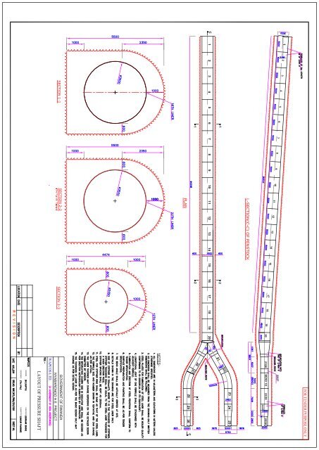
4 Proposed Methodology for Erection of pressure Shaft Linear<br />
General:<br />
The Bifurcation as proposed shall be fabricated in workshop with proper quality<br />
control so as to ensure Structural safety Combined with Hydraulic efficiency. The<br />
Branch pipes of shall be proportioned to ensure smooth stream line flow from the<br />
Header (3500 mm Dia to the branch2710mm dia) and to minimize hydraulic loses<br />
by introducing conical Reducers and Keeping the angle of deflection small (about 7<br />
degrees). A reducer piece is used to reduce the overall length of the penstock<br />
bifurcation. The reducer piece has a larger diameter of 2710 mm and smaller<br />
diameter of 2450 mm. The reducer piece will have the same angle of deflection as<br />
that of the bifurcation piece. The sickle plate is used as reinforcement system in the<br />
bifurcation which shall be properly welded to the bifurcation and ring girder.<br />
Proper Care Shall be taken while welding the reinforcement plate(sickle plate) / Tie<br />
rod /Ring Girder / with the plates of Wye piece and welding, cleaning & painting<br />
procedure enumerated elsewhere in this specification should be strictly adhered to.<br />
The methodology for erection of ferrule in the pressure shaft would consist of the<br />
following steps:<br />
1. Fabrication of the Wye-piece in the workshop.<br />
2. Hydrostatic testing<br />
3. Erection Setup.<br />
4. Loading of Wye Piecein the trailer.<br />
5. Transporation of Wye piece<br />
6. Lowering of Wye piece<br />
7. Matching and Pre-heat Treatment<br />
8. Final Welding<br />
9. NDT,Inspection and rectification<br />
10. Cleaning<br />
11. Final Coat of Painting<br />
12. Final Leakage testing/ acceptance test of the complete line and its<br />
Commissioning.
1. Fabrication of the Wye-piece<br />
The wye-piece is proposed to be erected in the workshop. The pieces should<br />
be erected as per the approved drawings from the client. The plate cutting<br />
profiles, Welding details, erection procedure, markings, cutting and beveling of<br />
the chamfers, rolling details etc should be approved by client before the<br />
fabrication of the wye-piece.<br />
a) Marking: The plates shall be laid out, marked as per the desired profile<br />
and trimmed to true shapes with great accuracy.<br />
b) Cutting and Beveling: Chamfers shall be prepared by flame cutting,<br />
shearing, planning or milling.<br />
c) Rolling: the plates shall be rolled to true curvature in a bending machine.<br />
d) Welding: The welding sequence shall be determined in advance and got<br />
approved before fabrication.<br />
e) The fabricator shall be responsible for the quality control.<br />
f) Stress Relieving: After fabrication, the bifurcation piece shall go undergo<br />
stress relieving locally or as a whole, if required.<br />
2. Hydrostatic Testing<br />
A <strong>hydro</strong>static test shall be conducted in the shop with a test pressure of 1.5<br />
times the design pressure or to a pressure which will develop a stress equal to<br />
0.8 times the yield point, whichever is more with the help of bulk heads.<br />
The bifurcation piece shall be completely filled with the water and pressure<br />
shall be applied three times successively increasing and decreasing at uniform<br />
rate.<br />
3. Erection Set Up:<br />
a. Gantry crane: capacity 30mt, capable of lowering up to 300m,span 9mtr<br />
c/c and for both the shaft, for unloading, lowering and matching of ferrules.<br />
b. Auxiliary Winch: Suitable capacity, height of lift 300m with attached<br />
closed bucket for carrying workmen, materials, machinery, tools &<br />
tackles, working platform.
c. Working platform/ Inspection Trolley: Circular platform for dia<br />
5800mm would be fabricated<br />
The platform would be of removable type and it would be welded to<br />
the ferrule by ISMC 100 inserted through the box of ISMC 250<br />
welded to the top of platform at eight locations. The platform is<br />
fixed from the top only and there is no need of any workmen to go<br />
below the platform to fix it. This is essential to safety of the<br />
workmen.<br />
The platform base would be formed from ISMB 200 with a circular<br />
ring of ISMC 200.<br />
It would be covered by a steel grating of 25 mmx25mm box and a<br />
circular plate of 1m dia of 20mm thickness at the center.<br />
d. Bucket: A bucket of size 2m x 2m x 2.5m would be fabricated with covered<br />
top and removable railing of for safety precautions, to be attached to the<br />
auxiliary winch.<br />
e. Illumination: Proper illumination would be done inside the shaft at an interval<br />
of 50m. Halogen lights would be fixed to the wall of the shaft with proper<br />
anchors. A separate power cable arrangement will be installed and would be<br />
independent from other works.<br />
4. Loading of Wye- Piece<br />
The Wye-piece would be lifted by the crane of capacity of 30 m and shall be put<br />
on the rolling platform in a vertical position. The Wye-piece shall be properly tuck<br />
welded to assure the proper transportation through rails.<br />
5 .Transportation of Wye Piece:<br />
a. As transport by rail of Wye-piece over 3.5m in Diameter is usually not feasible,<br />
W-Piece of the size Should be Fabricated in a Field fabricating plant near the<br />
site of installation, either from the plates shaped directly from the mill or from<br />
plates pre-fabricated at the contractor home plant, the plates were to be
fabricated cut to size, edged, enrolled then transported to the field fabricating<br />
plant for compaction internal spiders, were used during fabrication to keep the<br />
Y piece in shape perfect with its stiffeners and bi furcation.<br />
b. The Y piece should be transported either from the nearest railway station or<br />
from the field fabricated plant to the site nearest to the installation by truck,<br />
trailers, barge, or other means suited at the site. Upon arrival at the site of<br />
installation, the Y piece lifted in place by cable way, gantry crane or by other<br />
means.<br />
c. The finished Y piece will be placed on low bed trailer and will properly clamped<br />
with temporary cleats welded to the truck bed and also tightened with turn<br />
buckles to avoid any displacement of Y piece during transportation through<br />
tunnel approach number B1 to the desired location of the junction of the<br />
bifurcation.<br />
d. 2 or more no. of lifting hooks around periphery of the Y piece will be welded at<br />
suitable points of the Y piece.<br />
e. Then the Y piece would be transported to the desired location of the junction of<br />
bi furcation.<br />
6. Lowering of Wye- Piece in the final position:<br />
<br />
As the trailer reaches the Erection Point in the cavern, all temporary cleats etc<br />
would be removed and, turn buckles are released. The gantry positioned to<br />
the center of wye-piece would lift the wye-piece from the lifting hooks<br />
attached so as to free the trailer.<br />
After the Wye- Piece is rested on the ground, the working platform is welded<br />
inside the Wye- Piece to assist the workmen for sitting. All welding machines,<br />
cutting sets, mother oven and other tools & tackles required, would be loaded<br />
on the platform.<br />
3 skilled riggers and one foreman with required safety apparatus and<br />
communication wireless set are deputed at the platform to guide the exact<br />
position and lowering of Wye- Piece.
At least 3 skilled workmen must be ready for assistance stationed in the<br />
important requisite locations of the ground to monitor the lowering of Wye-<br />
Piece.<br />
Now the Wye- Piece 3.5 dia. side of the Wye- Piece is positioned towards the<br />
header along the alignment and well matched to the bi furcating pieces by<br />
starting to lower with the main hook of the gantry crane. A set of workmen<br />
must be there to monitor the lowering Wye- Piece and provide assistance if<br />
required.<br />
The entire activity is monitored and coordinated with the crane operator and<br />
the foreman sitting inside the Wye- Piece.<br />
Once the Wye- Piece reaches its position, then the matching gang with fitters,<br />
tank welders, workmen and <strong>electric</strong>ian along with tha main power cable are<br />
positioned for the further job.<br />
7. Matching & pre-heat treatment:<br />
After the position of Wye- Piece perfect to the header and the branches of the<br />
pressure conduit, the <strong>electric</strong>ian will connect the welding machines with the<br />
power cable and the edge matching of the joint starts.<br />
Matching of all the joints in Wye- Piece and adjoining header and branch<br />
pipes will be done from the outside the ferrule which will ensure the following<br />
benefits:<br />
a. Welder will be free of any hindrance of the locking cleats, L-keys,<br />
Matching screws, etc.<br />
b. No cleaning and grinding of inner surface would be required as the<br />
surface would be free from tack welds.<br />
For matching from outside arrangement suitable to the site specific are made.<br />
The edges may be matched with the help of wedge, L-keys and cleats. The<br />
root gap may be maintained throughout the joint with the help of short turn<br />
buckles installed at the joint.<br />
After matching, the backing strip is welded from outside at the joint.
Pre Heat Treatment<br />
a. Preheating coil (width 300mm) and insulation wool arrangement may<br />
be required outside Wye Piece, adjoining header and Branch pipes.<br />
b. This arrangement is tack welded to the Wye Piece for heating and<br />
connected to the heating panel having requisite sensitivity.<br />
c. A current regulator is installed to regulate the heating process in<br />
controlled manner.<br />
The complete process of matching and start of pre-heating would take<br />
around 4-5 hours.<br />
8. Welding of Joint:<br />
After the matching gang completes its Job, Welders and helpers along with<br />
the required tools & tackles are sent to the Welding Job.<br />
The welder would start welding, once the pre-heat temperature reaches<br />
200 o C which may be checked with help of thermo pens.<br />
The temperature would be maintained during welding of joint.<br />
The welding would be done as per the relevant Specification as approved<br />
by the <strong>project</strong> authority and according to the specification of ASME Section<br />
VIII & IX.<br />
After the welding is complete, the heating arrangement would be still kept<br />
ON for another 2 hrs. acting as post heat/stress relieving treatment.<br />
After 2 hours, the heating panel is switched OFF but the coils and insulting<br />
are not removed from the joint until the joint reaches back to the ambient<br />
temperature gradually.<br />
The reducer piece shall be welded to the Wye-piece and entire weld-length<br />
shall be checked by radiographic testing. The<br />
The sequence of operation may be outlined as specified below:<br />
A. Take over from civil team for erection.<br />
B. Lowering, matching and preheating of joints.
C. Welding of 2-3 joints.<br />
D. NDT and Inspection<br />
E. Removal of all temporary cleats, platform, Support, tools & tackles.<br />
F. Handover for backfill concreting.<br />
9. NDT, Inspection and rectification:<br />
All the erection circumferential joints would be 100% tested ultrasonically.<br />
The radiographic examination shall be carried at all the welds too. The<br />
longitudinal joints of entire length of the penstock shall be radiographed for<br />
100% length. The circumferential joints shall be spot radiographed for 10%<br />
length of each joint plus 100 mm on both sides of weld section.<br />
All the T junctions between longitudinal and circumferential joint shall be<br />
radiographed.<br />
After erection and welded of Wye Piece and adjoining Header and Branches are<br />
complete, NDT technician along with the department inspector is sent platform<br />
for easy access to all the joints.<br />
100% Ultrasonic testing (UT) would be performed on all the welded joints in front<br />
of the inspector and if any repair is found, it would be marked for rectification.<br />
All marked repairs are rectified from inside surface only and rechecked for<br />
conformation.<br />
After NDT is successfully completed the portion is handed over for backfilling<br />
concreting.<br />
10. Cleaning of the inner side of the wye-piece:<br />
After backfilling concreting of the entire length is completed, grouting is done by<br />
civil people through the grout holes provided in the ferrules.<br />
Once grouting is finished a team of welders, fitters and helpers are sent on the<br />
platform to fit and weld the grout holes which are already fabricated as per the<br />
drawing.<br />
The workmen would also clean and remove all tack welds, cleats, temporary<br />
structures, etc from the inner surface of the Wye-piece for final painting.
11. Final Leakage testing/ acceptance test of the complete line and its<br />
Commissioning.<br />
On completion of penstock erection, and before the final painting, the<br />
penstock is filled and checked for stability and tightness.<br />
The filling of the penstock shall be done at a slow rate and during filling the<br />
closing and tightness of all the valves, inspection openings and other<br />
accessories shall be checked and the penstock shall be properly vented at<br />
high points to prevent formation of air pockets.<br />
<br />
Any joint leakage shall be repaired and retested<br />
12. Final Painting:<br />
Final coat of painting would be applied on the entire length of Wye-piece along with the<br />
Header and Branch pipes by airless spray system.
NYABARONG HYDRO-ELECTRIC PROJECT (<strong>28</strong> MW)<br />
RWANDA, AFRICA<br />
TECHNICAL SPECIFICATIONS<br />
HYDRO-MECHANICAL WORKS
NYABARONG HYDRO-ELECTRIC PROJECT (<strong>28</strong> MW)<br />
RWANDA, AFRICA<br />
TECHNICAL SPECIFICATIONS<br />
HYDRO-MECHANICAL WORKS<br />
Prepared By___________________<br />
(AZHAR NAQVI)<br />
Checked By____________________<br />
(J.SAHU)<br />
Verified By____________________<br />
(S. R. DAS)<br />
Submitted By___________________<br />
(O. P. CHIBBER)
NYABARONG HYDRO-ELECTRIC PROJECT (<strong>28</strong> MW)<br />
RWANDA, AFRICA<br />
Technical Specifications<br />
(Hydro-Mechanical Works)<br />
CONTENTS<br />
SECTION NO. TITLE Page No.<br />
Section - 1 Intent of Technical Specifications and Scope of Works I<br />
Section - 2 Standards and Materials II<br />
Section - 3 Technical Documents III<br />
Section - 4 Spare Parts and Tools IV<br />
Section – 5 Description and Design Criteria V<br />
Section - 6 Manufacture X<br />
Section - 7 Electrical Works XI<br />
Section – 8 Erection XII<br />
Section – 9 Transportation and Storage XIII<br />
Section – 10 Quality Assurance, Inspection, Testing and Final Acceptance XIV<br />
Section – 11 Schedule for Hydro-mechanical Works XV
TABLE OF CONTENTS<br />
SECTION – 1<br />
INTENT OF TECHINICAL SPECIFICATIONS AND SCOPE OF WORK<br />
Clause No. Title Page No.<br />
1.1.0 Intent of Technical Specification 1<br />
1.1.1 General 1<br />
1.2 Scope of work 1<br />
1.2.1 General 1<br />
1.2.2 Spillway Radial Gates 2<br />
1.2.3 Stoplogs for Spillways 2<br />
1.2.4 Diversion Tunnel Gate 3<br />
1.2.5 Intake Trash Racks 3<br />
1.2.6 Power Intake Service Gate 4<br />
1.2.7 Power Intake Emergency Gate 4<br />
1.2.8 Draft Tube Gates 4<br />
1.2.9 Miscellaneous Systems and Equipment 5<br />
1.3.0 Conditions for Particulars Application 6<br />
1.3.1 General 6<br />
1.3.2 Inspection and Quality Assurance Plan 7<br />
1.3.3 Wastage of Steel 7<br />
1.3.4 Schedule and progress 7<br />
1.3.5 Delivery period 8<br />
1.3.6 Responsibilities of Contractor 8<br />
1.4.0 General Requirement 9<br />
1.5.0 Atmospheric Conditions 9<br />
1.6.0 Warranty 9
SECTION – 2<br />
I<br />
STANDARDS AND MATERIALS<br />
Clause No. Title Page No.<br />
2.1.0 Standards and Codes 11<br />
2.2.0 Standards for General Application 11<br />
2.2.1 General 11<br />
2.2.2 Standards for Design & Testing 12<br />
2.2.3 System of Units 14<br />
2.3.0 Material Standard 14<br />
2.3.1 General 14<br />
2.3.2 Spillway Radial Gate 15<br />
2.3.3 Vertical Lift Fixed Wheel Gates for Diversion 16<br />
Tunnel / Intake / Draft Tube<br />
2.3.4 Stoplogs for Spillway Radial Gates 17<br />
2.3.5 Electrically Operated Rope Drum Hoists 18<br />
2.3.6 Lifting Beam 19<br />
2.3.7 Gantry Crane 19<br />
2.3.8 Hoist Bridge, Trestles, Walkway railing, gantry girder etc. 21<br />
2.3.9 Hydraulic Hoist 21<br />
2.3.10 Trash Rack Cleaning Machine 22
SECTION – 3<br />
II<br />
TECHNICAL DOCUMENTS<br />
Clause No. Title Page No.<br />
3.1.0 Technical Documents 23<br />
3.1.1 General 23<br />
3.2.0 Designs & Drawings 24<br />
3.2.1 Drawings and data to be furnished by the bidders 24<br />
along with the Bid<br />
3.2.1.1 Radial Gates for Spillways 24<br />
3.2.1.2 Hydraulic Hoists for Radial Gates 24<br />
3.2.1.3 Support Structure for Hydraulic Hoist of Radial Gates 25<br />
3.2.1.4 Stoplogs for Spillways 25<br />
3.2.1.5 Lifting Beam for Spillway Stoplogs 25<br />
3.2.1.6 10 t Capacity (Tentative) Gantry Crane for Spillway Stoplogs 25<br />
3.2.1.7 Diversion Tunnel Gate / Power Intake Service Gate / 25<br />
Power Intake Emergency Gate / Draft Tube Gate<br />
3.2.1.8 Rope Drum Hoists for Diversion Tunnel Gate / Power 25<br />
Intake Service Gate / Power Intake Emergency Gate /<br />
Draft Tube Gate<br />
3.2.1.9 Hoist Support Structures for Diversion Tunnel Gate / 26<br />
Power Intake Service Gate / Power Intake Emergency<br />
Gate / Draft Tube Gate<br />
3.2.1.10 Intake Trash Rack 26<br />
3.2.1.11 Lifting Beam for Intake Trash Rack 26<br />
3.2.1.12 Trash Rack Cleaning Machine 26<br />
3.2.2 Drawings and Data to be furnished by contractor after 26<br />
award of work<br />
3.2. 3 Diagrams <strong>28</strong><br />
3.2.4 List of Schedules 29<br />
3.3.0 Progress Reports 32<br />
3.4.0 Installation, Operation & Maintenance Manual 32<br />
3.5.0 Inspection and Test Records 33
SECTION - 4<br />
III<br />
SPARE PARTS AND TOOLS<br />
Clause No. Title Page No.<br />
4.1.0 Spare Parts 34<br />
4.1.1 General 34<br />
4.1.2 General Spare Parts 34<br />
4.1.3 Mandatory Spares 35<br />
4.1.4 Additional Spares 37<br />
4.1.5 Tools and Appliances 37
SECTION – 5<br />
IV<br />
DESCRIPTION AND DESIGN CRITERIA<br />
Clause No. Title Page No.<br />
5.1.0 Design and Construction Requirements 38<br />
5.1.1 General 38<br />
5.1.2 Design Criteria 39<br />
5.2.0 Spillway Radial Gates 39<br />
5.2.1 General 39<br />
5.2.2 Specification Drawings 40<br />
5.2.3 Design Parameters 40<br />
5.2.4 Description and Design Criteria 40<br />
5.2.5 Description of Components and Design Criteria 41<br />
5.2.5.1 General 41<br />
5.2.5.2 Skin Plate 42<br />
5.2.5.3 Horizontal Girders and Stiffeners 42<br />
5.2.5.4 Arms 42<br />
5.2.5.5 Trunnion Hubs 43<br />
5.2.5.6 Trunnion Pins 43<br />
5.2.5.7 Trunnion Bush / Bearings 43<br />
5.2.5.8 Trunnion Brackets 43<br />
5.2.5.9 Trunnion Ties 43<br />
5.2.5.10 Seals 43<br />
5.2.5.11 Seal Seat, Seal Bases and Sill Beams 44<br />
5.2.5.12 Guide Rollers 44<br />
5.2.5.13 Load Carrying Anchorages 44<br />
5.2.5.14 Trunnion Girders or Yoke Girders and Anchor Girders 45<br />
5.2.5.15 Anchor Bolts or Anchor Plates 45<br />
5.2.5.16 Tolerance 45<br />
5.3.0 Stoplogs for Spillway Radial Gates 45<br />
5.3.1 General 45<br />
5.3.2 Specification Drawings 46<br />
5.3.3 Design Parameters 46<br />
5.3.4 Description and Design Criteria 46<br />
5.4.0 Vertical Lift Wheel Gates 47<br />
5.4.1 Diversion Tunnel Gate 47<br />
5.4.2 Specification Drawings 47<br />
5.4.3 Design Parameters 47<br />
5.4.4 Description and Design Criteria 48<br />
5.5.0 Power Intake Service and Emergency Gate 48<br />
5.5.1 General 48<br />
5.5.2 Specification Drawings 49<br />
5.5.3 Design Parameters 49
Clause No. Title Page No.<br />
V<br />
5.5.4 Description and Design Criteria 49<br />
5.6.0 Draft Tube Gates 50<br />
5.6.1 General 50<br />
5.6.2 Specification Drawings 50<br />
5.6.3 Design Parameters 50<br />
5.6.4 Description and Design Criteria 51<br />
5.7.0 Intake Trash Rack 51<br />
5.7.1 Design Parameters 51<br />
5.7.2 Description and Design Criteria 52<br />
5.8.0 Gantry Crane for Spillway Stoplogs 52<br />
5.8.1 Design Data for Gantry Cranes 52<br />
5.9.0 Trash Rack Cleaning Machine 53<br />
5.9.1 Design Data for Trash Rack Cleaning Machine 53<br />
5.10.0 Lifting Beams for operation of Spillway 53<br />
Stoplogs & Trash Racks<br />
5.11.0 Hoist Support Structures 53<br />
5.12. 0 Description of Components of Vertical Lift 54<br />
Gates and Embedded Parts<br />
5.12.1 Fixed Wheel Gates 54<br />
5.12.2 Spillway Stoplogs 55<br />
5.12.3 Skin Plate 55<br />
5.12.4 Horizontal Girders, Stiffeners and End Vertical Girder 56<br />
5.12.5 Seal 56<br />
5.12.6 Seal Seats, Seal Bases and Sill Beams 56<br />
5.12.7 Wheel Assembly 57<br />
5.12.8 Track / Bearing Plates & Bases 57<br />
5.12.9 Guide Plates & Guide Shoes / Guide Rollers 58<br />
5.12.10 Ballast 58<br />
5.12.11 Lifting Arrangement 58<br />
5.12.12 Anchor Bolts or Anchor Plates 59<br />
5.12.13 Tolerances 59<br />
5.13.0 Hydraulic Hoists for Spillway Radial Gates 59<br />
5.13.1 General 59<br />
5.13.2 Description 59<br />
5.13.3 Hydraulic Cylinder Assembly 60<br />
5.13.4 Cylinder Assembly Mounting and Support Structure 63<br />
5.13.5 Connecting Pipe 64<br />
5.13.6 Hoist Control module 66<br />
5.13.7 Hydraulic Fluids 71<br />
5.13.8 System Cleanliness 71<br />
5.13.9 Flushing 71
5.13.10 Miscellaneous Equipment Details 72<br />
5.13.11 Design Criteria of Hydraulic Hoists 72<br />
VI<br />
Clause No. Title Page No.<br />
5.13.12 Hoist Cylinder Assembly 75<br />
5.13.13 Cylinder Mounting Support Structure 75<br />
5.13.14 Design criteria for Piping 76<br />
5.13.15 Hydraulic Power Unit 76<br />
5.13.16 Miscellaneous Design Criteria 76<br />
5.13.17 Controls 77<br />
5.13.18 Life Expectancy 77<br />
5.13.19 Hoist Electrical Control Cabinet 77<br />
5.13.20 Enclosure 78<br />
5.13.21 Contactors 78<br />
5.13.21 Control Cabinet Lighting and Outlets 78<br />
5.14.0 Rope drum Hoists for operation of Diversion Tunnel 79<br />
Gate / Power Intake Service / Emergency Gate and<br />
Draft Tube Gates<br />
5.14.1 General 79<br />
5.14.2 Hoist Capacity 79<br />
5.14.3 Design Data for Rope drum Hoists 80<br />
5.14.4 Hoisting Speed 80<br />
5.14.5 Hoist Supporting Structure 80<br />
5.14.6 Components of the Hoists 81<br />
5.14.7 Mechanical Equipment 81<br />
5.14.7.1 Hoisting Ropes 81<br />
5.14.7.2 Rope Drums 82<br />
5.14.7.3 Gears 82<br />
5.14.7.4 Speed Reducers 82<br />
5.14.7.5 Gate Position Indicator 83<br />
5.14.8 Shafts 83<br />
5.14.8.1 General 83<br />
5.14.8.2 Dimensioning of Shafts 83<br />
5.14.8.3 Allowable Stresses 83<br />
5.14.8.4 Sheaves and Pulleys 83<br />
5.14.8.5 Sockets for Wire Ropes 84<br />
5.14.8.6 Turn Buckles & Equalizer Bars 84<br />
5.14.8.7 Bearings 84<br />
5.14.8.8 Couplings 84<br />
5.14.9 Electrical Equipment 84<br />
5.14.9.1 Efficiency of System 85<br />
5.14.9.2 Motors 85<br />
5.14.9.3 Electro-Magnetic Brakes 85<br />
5.14.9.4 Limit Switches 86
5.14.9.5 Wiring 86<br />
5.14.9.6 Manual Operation 87<br />
Clause No. Title Page No.<br />
VII<br />
5.14.9.7 Interlocking and Earthing 87<br />
5.14.9.8 Lubrication 87<br />
5.14.9.9 Miscellaneous 87<br />
5.15.0 Hoist Supporting Structure 88<br />
5.15.1 General 88<br />
5.16.0 Gantry Cranes for operation of Stoplogs for 88<br />
Spillway Radial Gates<br />
5.16.1 General 88<br />
5.16.1.1 Design Criteria 89<br />
5.16.2 Structural Components 90<br />
5.16.2.1 General 90<br />
5.16.2.2 Frame 90<br />
5.16.2.3 Legs 90<br />
5.16.2.4 Machinery Housing 91<br />
5.16.2.5 Operator’s Cabin 91<br />
5.16.2.6 Walkways, Ladders and Handrails 91<br />
5.16.2.7 Buffers 91<br />
5.16.3 Mechanical Equipment 92<br />
5.16.3.1 General 92<br />
5.16.3.2 Wheels and Axles 92<br />
5.16.3.3 Gantry Drive 93<br />
5.16.3.4 Hoisting Ropes 93<br />
5.16.3.5 Rope Drums 94<br />
5.16.3.6 Sheaves and Pulleys 94<br />
5.16.3.7 Gears and Speed Reducers 95<br />
5.16.3.8 Brakes 95<br />
5.16.3.9 Shafts 96<br />
5.16.3.10 Bearings 96<br />
5.16.3.11 Couplings 97<br />
5.16.3.12 Lifting Hook and Pulley Block 97<br />
5.16.3.13 Gear Box Cover 97<br />
5.16.3.14 Counter Weight 97<br />
5.16.3.15 Keys and keyways 97<br />
5.16.4.0 Electrical Equipment 97<br />
5.16.4.1 General 97<br />
5.16.4.2 Electric Motor 98<br />
5.16.4.3 Master Control Equipment 98<br />
5.16.4.4 Cables and Reels 99<br />
5.16.4.5 Wiring 100<br />
5.16.4.6 Limit Switch 100
5.16.4.7 Isolating Switches 100<br />
5.16.4.8 Protective Equipments 101<br />
5.16.4.9 Emergency Push Button 101<br />
Clause No. Title Page No.<br />
VIII<br />
5.16.4.10 Lighting at convenient outlets 101<br />
5.16.4.11 Interlocking and Earthing 101<br />
5.16.5.1 Wrenches and Tools 101<br />
5.16.5.2 Lubrication 101<br />
5.17.0 Lifting Beam for operation of Spillway Stoplogs 102<br />
and Trash Racks<br />
5.17.1 General 102<br />
5.17.2 Design Loading 102<br />
5.17.3 Structural design 103<br />
5.17.4 Component Details 103<br />
5.17.5 Design Data 104
SECTION – 6<br />
IX<br />
MANUFACTURE<br />
Clause No. Title Page No.<br />
6.1.0 Manufacture 105<br />
6.1.1 General Workmanship 105<br />
6.2.1 Tolerances and Fits 106<br />
6.2.2 Fabrication Tolerances 106<br />
6.2.3 Installation Tolerance 106<br />
6.3.0 Machine Finish 107<br />
6.4.0 Casting 107<br />
6.5.0 Forging 107<br />
6.6.0 Fabrication of Structural Steel 108<br />
6.6.1 Welding 108<br />
6.6.2 Riveting 110<br />
6.6.3 Turned and Fitted Bolts 110<br />
6.6.4 Set Screws 110<br />
6.6.5 Drilling and Reaming 110<br />
6.6.6 Punching 110<br />
6.7.0 Stress Relieving 110<br />
6.8.0 Painting 111<br />
6.8.1 General 111<br />
6.8.2 Painting Schedule 112<br />
6.8.2.1 Gates and Embedded parts 112<br />
6.8.2.2 Cranes, Hoists, Trash Rack Cleaning Machine and 113<br />
Supporting Structures<br />
6.8.2.3 Finishing Coats 113<br />
6.8.2.4 Embedded Parts in contact with concrete 114<br />
6.8.3 Surfaces not to painted 114<br />
6.8.4 Colour Scheme 114<br />
6.8.5 Handling of painted metal works 114<br />
6.8.6 Inspection and testing 114<br />
6.8.7 Field Painting 115<br />
6.8.8 Repair of Primer and Finished Coats 115<br />
6.9.0 Galvanizing 115<br />
6.10.0 Tests & Inspection 116<br />
6.10.1 General 116<br />
6.10.2 Tests of materials 116
SECTION – 7<br />
X<br />
ELECTRICAL WORKS<br />
Clause No. Title Page No.<br />
7.1.0 General 117<br />
7.1.1 Scope of Work 117<br />
7.1.2 Standards 117<br />
7.1.3 Colour Code 117<br />
7.2.0 Electric Motors 118<br />
7.2.1 General 118<br />
7.2.2 Rating 118<br />
7.2.3 Starting 118<br />
7.2.4 Windings and Insulation Class 119<br />
7.2.5 Ventilation and Type of Enclosure 119<br />
7.2.6 Bearings 119<br />
7.2.7 Shafts and Couplings 120<br />
7.2.8 Terminal Boxes and Earthing 120<br />
7.2.9 Noise Level and Vibrations 120<br />
7.2.10 Tests 121<br />
7.3.0 Auxiliary Works 121<br />
7.3.1 Auxiliary Switches 121<br />
7.3.2 Control Switches 121<br />
7.3.3 Anti-Condensation Heaters 122<br />
7.3.4 Protection Devices 122<br />
7.4.0 Terminal Points 123<br />
7.4.1 Scope of work 123<br />
7.4.2 Supply Tolerances 123<br />
7.5.0 Cables 123<br />
7.5.1 General 123<br />
7.5.2 Colour Code 123<br />
7.6.0 Earthing System 124<br />
7.7.0 Labels and Plates 124<br />
7.7.1 General 124<br />
7.7.2 Equipment Labels and Instruction Plates 124<br />
7.7.3 Instruction Plates 125
SECTION – 8<br />
XI<br />
ERECTION<br />
Clause No. Title Page No.<br />
8.1.0 General 126<br />
8.2.0 Installation of I st stage Embedded parts 126<br />
8.3.0 Installation of 2 nd stage Embedded Parts 126<br />
8.4.0 Installation of Gates, Hoists & Operating Mechanism 126<br />
8.5.0 Guidelines for Field Erection 126<br />
8.6.0 Placing of Concrete 127<br />
8.7.0 Erection Personnel 127<br />
8.8.0 Erection Limitation 127<br />
8.9.0 Notification 127<br />
8.10.0 Cooperation with other Contractors 127
SECTION – 9<br />
XII<br />
TRANSPORTATION AND STORAGE<br />
Clause No. Title Page No.<br />
9.1.0 Transportation 1<strong>28</strong><br />
9.2.0 Preparation for Dispatch 1<strong>28</strong><br />
9.3.0 Weights 1<strong>28</strong><br />
9.4.0 Marking 1<strong>28</strong><br />
9.5.0 Packing 129<br />
9.6.0 Storage 129
SECTION – 10<br />
XIII<br />
QUALITY ASSURANCE, INSPECTION, TESTING AND FINAL ACCEPTANCE<br />
Clause No. Title Page No.<br />
10.1.0 Quality Assurance 131<br />
10.2.0 Inspection, Testing and Maintenance 132<br />
10.2.1 General 132<br />
10.2.2 Place of Manufacture and Inspection 132<br />
10.3.0 Inspection 133<br />
10.4.0 Witnessing Shop Test, Inspection and Training 133<br />
10.5.0 Operational Tests 134<br />
10.5.1 General 134<br />
10.5.2 Dry Test 134<br />
10.5.3 Wet Test 134<br />
10.5.4 Leakage Tests 135<br />
10.5.5 Non-Destructive Tests 135<br />
10.5.5.1 General 135<br />
10.5.5.2 Radiographic and Ultrasonic Inspection 135<br />
10.6.0 Shop Assembly and Tests 137<br />
10.6.1 Gates / Stoplogs 137<br />
10.6.2 Gantry Cranes 137<br />
10.6.3 Lifting Beam 138<br />
10.6.4 Load Testing 139<br />
10.6.5 Load Testing of Anchorage Assemblies 139<br />
10.6.6 Shop Assembly Tests 139<br />
10.7.1 Field Tests 139<br />
10.7.1 Gates / Stoplogs 139<br />
10.7.2 Hoists / Gantry Crane 140<br />
10.7.3 Lifting Beam 140<br />
10.8.0 Final Acceptance 141<br />
10.9.0 Guarantee 141<br />
10.9.1 Failure to Meet Guarantee 141<br />
10.9.2 Defective Equipment 142<br />
10.9.3 Operation of Unsatisfactory Equipment 142
SECTION – 11<br />
XIV<br />
SCHEDULE OF UNIT RATES FOR HYDRO-MECHANICAL EQUIPMENT<br />
Clause No. Title Page No.<br />
11.1.0 Schedule of unit rates for 3500 mm x 5100 mm Spillway Radial Gates 143<br />
11.2.0 Schedule of unit rates for 3500 mm x 8260 mm Spillway Stoplogs 145<br />
11.3.0 Schedule of unit rates for 6700 mm x 6700 mm Diversion Tunnel Gate 146<br />
11.4.0 Schedule of unit rates for 6806 mm x 6850 mm Intake Trash Racks 148<br />
11.5.0 Schedule of unit rates for 4100 mm x 4100 mm Service Gate for Power Intake 149<br />
11.6.0 Schedule of unit rates for 4100 mm x 4100 mm Emergency Gate<br />
for Power Intake 151<br />
11.7.0 Schedule of unit rates for 4762 mm x 2480 mm Draft Tube Gate<br />
for Power House 152<br />
11.8.0 Schedule of unit rates for 10 t capacity Gantry Crane for Spillway Stoplogs 154<br />
11.9.0 Schedule of unit rates for Trash Rack Cleaning Machine 155
SECTION – 1<br />
XV<br />
INTENT OF TECHNICAL SPECIFICATIONS AND SCOPE OF WORK<br />
1.1.0 Intent of Technical Specifications<br />
1.1.1 General<br />
These Specifications are part of the requirements for various items related to the Work<br />
which are to be provided according to the stipulations of the contract. Hence, the<br />
instructions given herein form an integral part of, and are applicable to the Bidding<br />
Documents issued for the Works. Addendum to these Specifications may be issued, as<br />
required, during bidding and construction phases.<br />
These Specifications shall be read in conjunction with the Conditions of Contract, the<br />
specification Drawings and the schedule of prices and the Contractor shall comply with all<br />
provisions contained within the Bidding Documents and instructions of the Purchaser.<br />
Certain performance requirements, materials, features, design requirements and basic<br />
arrangement for Gates, hoist, stoplogs, cranes etc. are indicated herein. It is not the<br />
intention in these specifications to specify the complete details of the various components<br />
of the equipment. This is left to the experience and practice of Contractor who shall<br />
perform the complete design of all the equipment structure and furnish equipment which<br />
shall meet, in all respects the specified requirements in regard to performance, durability<br />
and satisfactory operation. However, certain features, materials and design requirement are<br />
specified and are intended to establish minimum standard for the work and to enable the<br />
bidder to submit a well planned bid.<br />
It is the intent of these specifications to establish acceptable standards of quality.<br />
Deviation from these specifications shall be considered for acceptance, provided that, in<br />
the opinion of the Engineer-in-Charge, the proposed substitutions are equal or superior in<br />
quality to those specified.<br />
All works shall be executed according to the Technical Specifications and Specification<br />
Drawings and requirements specified by Engineer-in-Charge, in professional and diligent<br />
manner and all supplies and works shall comply with the quality requirements defined in<br />
the relevant chapters of these Specifications and other Bidding Documents. The<br />
Contractor shall endeavor to provide all such necessary efforts in order to comply with the<br />
intent of these Specifications to the satisfaction of the Engineer-in-Charge.<br />
1.2 Scope of Work<br />
1.2.1 General<br />
These specifications cover the requirements of design, fabrication, shop assembly, shop as<br />
well as field painting, transportation, supply, erection, testing, commissioning, (including<br />
provision for all labour, plant, material) satisfactory operation and equipment performance<br />
guarantee of the following equipment at site complete in all respects for Nyabarongo<br />
Hydro-<strong>electric</strong> Project, Rwanda, Africa in accordance with these Technical Specifications
and Specification Drawings. The materials, workmanship, technical requirements,<br />
equipment, accessories, supplies and services required, shall be as set forth in this<br />
Technical Specifications.<br />
It shall also include the spares required for satisfactory operation and maintenance of<br />
Gates, Hoists and allied equipment for a period of five years from the date of<br />
commissioning of the equipment as set forth in this Technical Specifications and<br />
Specification Drawings. The description and quantity of spares required for various gates,<br />
hoists and their associate equipment have been indicated Section - 4 of these<br />
specifications.<br />
The scope of work also covers unloading, stacking operation, storage and preservation of<br />
components of gates and their hoisting arrangement, stoplogs, lifting beams, Gantry<br />
Cranes and their accessories in the stockyards of the contractor at the <strong>project</strong> site before<br />
they are transported, installed, tested and commissioned at their respective Sites.<br />
1.2.2 Spillway Radial Gates<br />
1.2.2.1 3 (Three) sets of Radial gates suitable for 3(three) openings of 3500 mm x 5100 mm<br />
each for spillway complete in all respects with skin plate, vertical stiffeners, horizontal<br />
girders, radial arms, trunnion, trunnion brackets, trunnion tie beam, walkway bridge,<br />
approach ladder along with all accessories such as seals, guide rollers, lifting brackets,<br />
trunnion brackets etc., and other appurtenances. Each gate will be operated by means of<br />
twin cylinder hydraulic hoist.<br />
1.2.2.2 3 (Three) sets of embedded parts for Radial Gates for 3(three) openings of spillway<br />
such as wall plates, guide roller path, sill beams, seal seats, yoke girder, anchor girder,<br />
anchor tie flats, load carrying anchors, 1 st stage anchor bolts and 2 nd stage embedded parts<br />
etc. complete in all respects.<br />
1.2.2.2 (a) Walkway of 1200 mm width to access trunnion assemblies.<br />
1.2.2.3 3 (Three) sets of hydraulic hoists (two cylinders per set) of adequate capacity for<br />
operation of Spillway Radial gates mentioned under para 1.2.2.1 above consisting of<br />
hydraulic cylinder assembly, cylinder assembly mounting and support structure,<br />
connecting piping, hoist control module including hydraulic power unit, <strong>electric</strong>al control<br />
cabinet, <strong>electric</strong> motor, gate position indicator, frame and housing along with all<br />
accessories and appurtenances and hydraulic fluid as per these specifications and<br />
arrangements complete in all respects.<br />
1.2.2.4 3 (Three) sets of hoist supporting structure / frame of adequate capacity for supporting<br />
the hydraulic hoists for Spillway Radial Gate as defined at 1.2.2.3 including Trunnion<br />
Pedestal, anchors etc. complete in all respects.<br />
1.2.3 Stoplogs for Spillways<br />
1.2.3.1 1 (one) set of sliding type stoplogs (consisting of 3 units) suitable for 3(three) openings<br />
of 3500 mm x 8260 mm each for spillway consisting of non-interchangeable top,<br />
intermediate and bottom unit of size 3500 mm x <strong>28</strong>00 mm each complete in all respects<br />
with skin plate, vertical stiffeners, horizontal girders, guide shoes, sliding blocks, seals,<br />
lifting lugs etc. and other appurtenances to be used for isolating spillways for the<br />
maintenance of radial gates.
1.2.3.2 3 (three) sets of embedded parts for Stoplogs for 3(three) openings of spillway such as<br />
anchor bolts, sill beams, seal seats and bases, tracks and bases, guides, 1 st stage anchor<br />
bolts and 2 nd stage embedded parts etc. complete in all respects including 3(three) sets of<br />
anchor bolts, dogging devices at top of its groove for storage of Stoplog units.<br />
1.2.3.3 10 t Capacity (Tentative) Gantry Crane for operation of Spillway Stoplogs<br />
10 t Capacity (tentative) Gantry Crane shall have <strong>electric</strong>ally operated rope drum hoist for<br />
operation of spillway stoplogs through a lifting beam of adequate capacity with all<br />
accessories including cross travel mechanism, gantry frame, gantry structure, counter<br />
weight, L T mechanism, operator’s cabin, gantry travel rails and rail fixing fixtures,<br />
operators cabin etc. complete in all respects.<br />
1.2.3.4 1 (one) no. of lifting beam of adequate capacity for Spillway Stoplogs with automatic<br />
engaging and disengaging device hooks, side guide shoes/rollers, link bars/ flats etc.,<br />
complete in all respects to operate the stoplog units.<br />
1.2.4. Diversion Tunnel Gate<br />
1.2.4.1 1(One) No. fixed wheel type vertical lift gate suitable for 1(one) opening of 6700 mm x<br />
6700 mm for Diversion Tunnel comprising of three units spliced together and operated by<br />
rope drum hoist of adequate capacity complete in all respects with skin plate, vertical<br />
stiffeners, horizontal girders, wheel assemblies, guide shoes, seals, lifting lugs, lifting<br />
arrangement etc. and other appurtenances for the purpose of plugging of diversion tunnel.<br />
1.2.4.2 1(One) set of rope drum hoists of adequate capacity mounted on steel trestles for<br />
operation of Diversion Tunnel gate mentioned under para 1.2.4.1 above consisting of<br />
wire ropes, drums, end reduction units, central drive units including worm reducers, DC E.<br />
M. brakes, <strong>electric</strong> motors, gate position indicators, arrangements for manual drive,<br />
suitable cover for the hoist equipment etc. complete in all respects.<br />
1.2.4.3 1 (One) set of hoist supporting structure of adequate capacity for supporting the rope<br />
drum hoist for Diversion Tunnel Gate as defined at 1.2.4.2 including removable<br />
guides, trestle, base plates, anchors etc. complete in all respects.<br />
1.2.5 Intake Trash Rack<br />
1.2.5.1 1 (One) set of Trash Rack suitable for 1(one) opening of 6806 mm x 6850 mm for Power<br />
Intake consists of two panels. Trash Racks will comprise of trash bars, horizontal girders,<br />
end girders / framing channels and lifting lugs etc. and other appurtenances.<br />
1.2.5.2 1 (one) set of embedded parts for Intake Trash Rack for 1(one) opening of Power Intake<br />
including framing channels, sill beam, and anchorages. 1 st stage anchor bolts and 2 nd stage<br />
embedded parts etc. complete in all respects.<br />
1.2.5.3 1 (one) No. of Trash Rack Cleaning machine for removing trashes collected on the trash<br />
rack panels mentioned under para 1.2.5.1 above. An auxiliary hoist shall also be provided<br />
on Trash Rack Cleaning Machine for raising and lowering of Trash Rack Panels during<br />
maintenance etc. complete in all respects.<br />
1.2.5.4 1 (one) no. of lifting beam of adequate capacity for handling of Trash Racks under<br />
water with automatic engaging and disengaging device hooks, side guide shoes/rollers,<br />
link bars/ flats etc., complete in all respects to operate the stoplog units.
1.2.6 Power Intake Service Gate<br />
1.2.6.1 1(One) No. fixed wheel type vertical lift Service Gate suitable for 1(one) opening of<br />
4100 mm x 4100 mm for Power Intake comprising of two units spliced together and<br />
operated by rope drum hoist of adequate capacity complete in all respects with skin plate,<br />
vertical stiffeners, horizontal girders, end vertical girder, seal assemblies, wheel<br />
assemblies, guide shoes, seals, lifting lugs etc. and other appurtenances.<br />
1.2.6.2 1(One) set of embedded parts for Power Intake Service Gate for 1(one) opening of<br />
Power Intake including stainless steel tracks, seal seats, sill beam, guides, bases and<br />
anchorages including latching / dogging arrangement, 1 st stage anchor bolts and 2 nd stage<br />
embedded parts etc. complete in all respects.<br />
1.2.6.3 1(One) set of rope drum hoists of adequate capacity mounted on steel trestles for<br />
operation of Power Intake Service Gate mentioned under para 1.2.6.1 above consisting<br />
of wire ropes, drums, end reduction units, central drive units including worm reducers, DC<br />
E. M. brakes, motors, gate position indicators, arrangements for manual drive, suitable<br />
cover for the hoist equipment etc. complete in all respects.<br />
1.2.7 Power Intake Emergency Gate<br />
1.2.7.1 1 (one) No. fixed wheel type vertical lift Emergency Gate suitable for 1(one) opening of<br />
4100 mm x 4100 mm for Power Intake comprising of two units spliced together and<br />
operated by rope drum hoist of adequate capacity complete in all respects with skin plate,<br />
vertical stiffeners, horizontal girders, end vertical girder, seal assemblies, wheel<br />
assemblies, guide shoes, seals, lifting lugs etc. and other appurtenances.<br />
1.2.7.2 1(One) set of embedded parts for Power Intake Emergency Gate for 1(one) opening of<br />
Power Intake including stainless steel tracks, seal seats, sill beam, guides, bases and<br />
anchorages including latching / dogging arrangement, 1 st stage anchor bolts and 2 nd stage<br />
embedded parts etc. complete in all respects.<br />
1.2.7.3 1(One) set of rope drum hoists of adequate capacity mounted on steel trestles for<br />
operation of Power Intake Emergency Gate mentioned under para 1.2.7.1 above<br />
consisting of wire ropes, drums, end reduction units, central drive units including worm<br />
reducers, DC E. M. brakes, motors, gate position indicators, arrangements for manual<br />
drive, suitable cover for the hoist equipment etc. complete in all respects.<br />
1.2.7.4 1 (One) set of hoist supporting structure of adequate capacity for supporting the rope<br />
drum hoist for Power Intake Service Gate as defined at 1.2.6.3 and Power Intake<br />
Emergency Gate as defined at 1.2.7.3 including removable guides, trestle, base plates,<br />
anchors etc. complete in all respects.<br />
1.2.8 Draft Tube Gates<br />
1.2.8.1 2 (Two) sets of Draft Tube Gates suitable for 2(two) openings of 4762 mm x 2480 mm<br />
for Draft Tube of the power house complete in all respects with skin plate, seal assemblies,<br />
guide shoes, stiffeners, end vertical girders, horizontal girders, slide blocks, collapsible<br />
spring loaded guides, lifting arrangements, latch arrangements, filling valves, lifting lugs<br />
etc. and other appurtenances.
1.2.8.2 2 (Two) sets of embedded parts for 2(two) openings of Draft Tubes including stainless<br />
steel tracks, seals, sill beams, guides, 1 st stage anchor bolts and 2 nd stage embedded parts<br />
etc. complete in all respects.<br />
1.2.8.3 2 (Two) sets of rope drum hoists of adequate capacity mounted on steel trestles for<br />
operation of Draft Tube Gates mentioned under para 1.2.8.1 above consisting of wire<br />
ropes, drums, end reduction units, central drive units including worm reducers, DC E. M.<br />
brakes, motors, gate position indicators, arrangements for manual drive, suitable cover for<br />
the hoist equipment etc. complete in all respects.<br />
1.2.8.4 2 (Two) sets of hoist supporting structures of adequate capacity for supporting the rope<br />
drum hoists for Draft Tube Gates as defined at 1.2.8.3 including removable guides,<br />
trestle, base plates, anchors etc. complete in all respects<br />
1.2.9 Miscellaneous Systems and Equipment<br />
1.2.9.1 Reservoir Control, Instruments and Remote Control<br />
i) One complete set of remote controls for automatic reservoir level control system.<br />
ii)<br />
iii)<br />
Two sets of water level measuring instruments.<br />
Four sets of gate position measuring equipment<br />
The remote control system which is microprocessor control based shall consist of one<br />
operator station located at the top of dam and shall be supplemented by indication status<br />
stations at powerhouse control room.<br />
The main items of control and equipment shall comprise the following:<br />
a) Control and operation of Spillway radial gates.<br />
b) Gate position indication of Spillway radial gates, Intake service gate, Intake<br />
emergency gate and Draft tube gates.<br />
c) Two sets of water level indication and monitoring along with necessary alarms<br />
provided near spillway.<br />
d) Monitoring and indication of discharge measurements for discharge through spillway<br />
radial gates.<br />
e) System for ascertaining balancing of intake gate and draft tube gate.<br />
f) Inter-lock for preventing accidental opening of intake gate when draft tube gates are<br />
lowered.<br />
All the necessary transducers and instrumentation, terminals, contacts, cabling etc. for<br />
above at various locations shall be provided and incorporated in the remote control<br />
system.<br />
Operator’s station shall include operator’s consoles, which comprise colour C.R.T.<br />
(minimum 35 cm) screen with push buttons for operation and mimic panel, which indicate<br />
the gate movement. The operator shall be able to view the gate position or any gate status<br />
with the help of graphic display in the C.R.T screen.<br />
The system shall also have a printer (minimum 30 cps) for printing various logs,<br />
instructions and reports. Interlocking shall be provided between the operator’s station at<br />
dam top and the local control panels provided for individual gate operation. System design<br />
should be such that the operation can be done from local control panels, only with the<br />
permission of operator of station.
All the input display from field including water level of reservoir shall be displayed at<br />
both the C.R.T. screens. The system should continuously monitor the reservoir level and<br />
depending upon its level, it shall be able to calculate the input discharge into reservoir. In<br />
addition to this, the gate openings of spillway gates should be displayed in the form of<br />
graphic displays. The system shall be able to display the output discharge through spillway<br />
radial gates so that the operation of spillway gates can be carried out in auto mode.<br />
The system shall include various instructions like water level transmitters, sensors for<br />
opening indication of spillway gates, intake gate and height (opening) measurements.<br />
One uninterrupted power supply to provide back-up (minimum 30 minutes) to the system<br />
in case of failure of main power supply to equipment shall also be provided.<br />
1.2.9.2 Diesel Generating Set<br />
A 3 phase synchronous type diesel generating set of 250 KVA, 415 Volts, 50 Hz is<br />
envisaged for the emergency operations of the <strong>hydro</strong>-mechanical equipment at the dam<br />
site. The diesel generating set shall be located in the dam area to provide back-up supply<br />
to gate operating equipment and to the computerized control system in case of power<br />
failure.<br />
1.3.0 Conditions of Particular Application<br />
1.3.1 General<br />
(a) Dry as well as wet tests are to be carried out for all the gates and stoplogs by the supplier<br />
free of cost and rectification of defects noticed during tests or during the guarantee period<br />
(not less than 12 months after commissioning and handing over) are within the scope<br />
of supply.<br />
(b) Shop as well as field painting is included in the scope of supply.<br />
(c) 1 st and 2 nd stage concreting shall be done under supervision of gate contractor. The<br />
responsibility of correctness and accuracy of alignments would rest with the Contractor. It<br />
has to be ensured that appropriate erection tolerances are maintained and gate and<br />
embedment match perfectly.<br />
Ladders and rungs on concrete face for approaching the trunnion piers, the cat walkways<br />
on the downstream of the pier for approaching the trunnions for maintenance is in the<br />
scope of supply.<br />
The design, fabrication, supply and erection of 1 st stage embedded parts and 2 nd stage<br />
embedded parts are included in this scope of works. The contractor when ordered in<br />
writing by the Engineer-in-Charge shall perform extra work in furnishing the items not<br />
covered in the specifications or included in the schedule but forming an inseparable part of<br />
the work contracted for. Extra work and materials will ordinarily be paid for at a lump<br />
sum or unit price agreed upon by the contractor and the Engineer-in-Charge, as stated in<br />
the orders; whenever, in the judgement of the Purchaser, it is impracticable because of<br />
nature of the work or for any other reason whatsoever, to fix the price in the order, the<br />
payment of extra works and materials shall be made on the basis of actual cost as<br />
determined by the Engineer-in-Charge plus 10% allowance for superintendence, use of<br />
tools, tackles and shop etc.
Note:<br />
6<br />
Before undertaking manufacture, exact site dimensions should be verified by the<br />
Contractor and the equipment should match with site details. Engineer-in-Charge will not<br />
be responsible for any variation whatever in the site dimensions and it will be the<br />
responsibility of Contractor for matching site dimensions at no extra cost.<br />
1.3.2 Inspection and Quality Assurance Plan<br />
All supplies shall be subject to inspection and test by the Engineer-in-Charge to the extent<br />
practicable at all times and places. Shop tests shall also be subject to inspection and test by<br />
the Purchaser and the Purchaser shall depute Engineers for witnessing shop tests and<br />
training in works and designs as detailed in Section 6 of these specifications. Inspection<br />
shall be carried out in accordance with relevant Indian standards or equivalent<br />
International standards where Indian standards are not available or as described elsewhere<br />
in these specifications. The cost of carrying out the test / inspection and training shall<br />
be borne by the contractor and included in the price schedule for inspection and<br />
testing.<br />
Quality Assurance system and detailed Quality Assurance plans for the manufacture<br />
and supply of all the major components and equipment submitted by the contractor shall<br />
be finalized before the award of contract.<br />
1.3.3 Wastage of Steel<br />
1.3.4 Schedule<br />
The payment will be made only for the net weight of gates based on the sectional unit<br />
weight as per table of standard sections (supplied by SAIL) and used in the gates and<br />
hoists. The weight of nuts, bolts, rivets, welding etc., will not be considered in the net<br />
weight of gates. All the wastage of steel section supplied by the main producer will be<br />
on the contractor’s account and the contractor should consider this aspect while quoting<br />
the rates.<br />
Within 45 (Forty Five) calendar days after the date of commencement, the contractor<br />
shall submit to the Engineer-in-Charge for his approval the schedule of designs, drawings,<br />
fabrication and transportation of the equipment so as to ensure its delivery within the<br />
specified period. The schedule shall clearly state all the stages of fabrication to enable the<br />
Engineer-in-Charge to plan his inspection accordingly as stated in these specifications.<br />
The time and the date of completion of works as stipulated in the tender document shall<br />
be deemed to be the essence of the contract. However, certain alterations can be<br />
suggested by the bidder keeping in view the programme of erection, front availability and<br />
the completion date The contractor shall submit along with his bid a detailed<br />
programme based on the dates indicated in the tender document or alternatively his own<br />
time schedule giving shorter delivery / erection period taking into consideration the gate<br />
by which the erection front can be made available to him. The schedule shall be within the<br />
time frame agreed above consisting of adequate number of activities covering various key<br />
phases of the work such as designs, drawings, procurement, manufacturing, shop assembly<br />
(equipment wise), sand blasting and painting, shipment, field erection and testing<br />
activities. This network shall also indicate the interface facilities to be provided by the<br />
Engineer-in-Charge if any and the dates by which such facilities are needed. It shall
7<br />
Also indicate the details of resources like manpower/machinery envisaged in the part and<br />
to be mobilized by the contractor for all stages of erection.<br />
The contractor shall so organize his resources and perform his work as to complete it not<br />
later than the date agreed to by him. The time for completion of the works contracted for,<br />
shall be reckoned from the date of issue of commencement. During the performance of the<br />
contract, if in the opinion of the Engineer-in-Charge, proper progress is not maintained<br />
suitable changes shall be made in the contractor’s operation to ensure proper progress.<br />
1.3.5 Delivery Period<br />
Time of delivery at the <strong>project</strong> site is the essence of the contract and the contractor shall<br />
abide by milestone, the time being reckoned from the commencement. Separate schedule<br />
shall be submitted for each gates and hoisting equipment.<br />
1.3.6 Responsibilities of Contractor<br />
The contractor shall be responsible for:<br />
a. The quality of materials and workmanship in all the items of work.<br />
b. Strict adherence to the dimensions of parts shown on approved drawings unless deviations<br />
are specifically authorized in writing by the Engineer-in-Charge or Engineer-in-Charge.<br />
c. Strength of all parts of gates and hoists when operated under the worst conditions of load<br />
and under conditions of closure during periods of maximum flow/ discharge as applicable.<br />
d. It is Contractor’s responsibility to ensure that all components supplied in accordance with<br />
these specifications shall fit correctly to each other. In the event of any field modifications<br />
being required due to errors in shop fabrication, Contractor shall bear the full cost of such<br />
modifications. Any such changes shall be shown on the drawings and accepted in writing<br />
by Engineer-in-Charge, before being made by Contractor.<br />
e. Satisfactory performance of the entire work under all operating conditions without signs of<br />
undue strain and without damage, breakdown or deterioration of any of the parts due to<br />
faulty or incorrect or unsuitable material, workmanship or design.<br />
f. Freedom from vibrations of any part or parts under the most severe operating conditions<br />
beyond permissible limits.<br />
g. The water tightness of the gate seals, oil and water tightness of hoist cylinders, oil tanks,<br />
all pipes and joints, valves, bearings, stuffing boxes, pumps and controls.<br />
h. The strength, accuracy and adequacy of all parts of gates, hoists, hoist support structures<br />
and cranes etc. in all respects.<br />
i. The contract documents and specifications do not specify in complete details the various<br />
components of the equipment and only indicate a basic arrangement for the gates, hoists,<br />
cranes, and stoplogs etc. It is the contractor’s responsibility to perform the complete<br />
design of all the equipment, structure and fabrication within the parameters laid down in
8<br />
the specifications. The contractor shall supply and erect all equipment in a complete shape,<br />
which will meet the requirements regarding performance, durability and satisfactory<br />
operation.<br />
j. The principal parts of all the equipment are mentioned in these specifications which<br />
outline the general features to be adopted in design. Any deviations from the specified<br />
requirements shall be done only with the approval of the Engineer-in-Charge<br />
k. The contractor shall visit and carefully examine the site of the work and the adjacent<br />
premises and shall conduct necessary investigations to acquaint himself thoroughly with<br />
the facilities for handling the specified equipment at the site. A thorough investigation<br />
shall be made of potential interferences and difficulties that may be encountered in the<br />
proper and complete execution of the work specified. No plea of ignorance of existing or<br />
foreseeable conditions, that create difficulties or encumbrances in the execution of the<br />
work, will be accepted as an excuse for any failure on the part of the contractor to fulfill in<br />
every detail the requirements of the Contract Document. Furthermore, a plea of ignorance<br />
will not be accepted as a basis for any claim whatsoever.<br />
1.4.0 General Requirement<br />
The contractor shall carefully study the Technical Specifications and Specification<br />
Drawings and shall intimate the Engineer-in-Charge if any error / omission is discovered.<br />
As a result of such interaction, if some corrections / modifications are required, the same<br />
shall be brought to the notice of all the contractors by the Engineer-in-Charge before the<br />
date of submission of the tender.<br />
1.5,0 Atmospheric Conditions<br />
The equipment called for under these specifications shall be suitable for continuous outdoor<br />
operations in the climate at the site of Nyabarongo Hydro-<strong>electric</strong> Project, Rwanda, Africa with<br />
temperature variation from minimum to maximum and humidity etc. as specified in other chapters<br />
of this document.<br />
1.6.0 Warranty<br />
The contractor shall furnish warranty of the equipment for a minimum period of one<br />
year from the date of the final acceptance of equipment or commissioning or handing over<br />
to <strong>project</strong> authority whichever is later. The contractor shall guarantee among other things<br />
the following items.<br />
a) Quality and strength of the materials used.<br />
b) Satisfactory operation of the equipment.<br />
c) Safe stresses in all parts under all conditions of operations.<br />
d) Protection of equipment against vibration and corrosion.<br />
The Contractor shall at his own expenses, correct the defects, furnish and install new parts<br />
and materials approved by the Engineer-in-Charge in all the equipment covered under<br />
para 1.2.2. to 1.2.9 within 12 months from the date of final acceptance of equipment or<br />
commissioning or handing over to <strong>project</strong> authority whichever is later. The contractor
shall assume all responsibility for direct damages causing personal injury or property<br />
damage due to any manufacturing defects resulting in the failure of the equipment being<br />
supplied under these specifications.<br />
Final acceptance of work takes place only after completion of the tests and commissioning<br />
described elsewhere in these Specifications.<br />
9
SECTION – 2<br />
10<br />
STANDARDS AND MATERIALS<br />
2.1.0 Standards and Codes<br />
(a) General<br />
Works, design, testing, workmanship, material and supplies shall conform to the relevant<br />
Indian Standards. Wherever the Indian Standards are not existent or silent authoritative<br />
Standards and Codes like IEC or ISO Recommendations other than Indian Standards or<br />
those specified in the Bidding Documents, which ensure an equal or higher quality, may<br />
also be acceptable.<br />
All standards and codes referred to shall be the latest current issues irrespective of the year<br />
mentioned.<br />
When IEC or ISO Recommendations or other Standards are referred to, the edition shall<br />
be that current at the time of submittal of design.<br />
The contractor shall supply three copies in English and one in original language of any<br />
national standards which are approved for use under the contract.<br />
(b) Indian Standards and Codes<br />
Throughout the duration of the contract, the materials, equipment, services, design and<br />
workmanship shall conform to the applicable Indian Codes and Standards only if not<br />
otherwise specified.<br />
It is the Contractor’s duty to acquaint himself with all Indian Codes and Standards related<br />
to the works and he shall procure and keep at his works at the site a copy of each of such<br />
applicable documents.<br />
(c) International Standards and Codes<br />
The International Standards / Codes may be adopted provided that:<br />
- The Standards /codes proposed are at least as stringent as the equivalent Indian Standards<br />
relevant to the works or higher quality compared to those specified, and approved or if<br />
there is no applicable Indian Standards / codes for the specific item concerned,<br />
furthermore, that the Contractor submits for approval copies of the standards which he<br />
proposes to use.<br />
2.2.0 Standards for General Application<br />
2.2.1 General<br />
Standard publications issued by the following organizations of standardization are<br />
considered being approved standards for the works with a priority to use Indian Standards.<br />
BIS:<br />
ASTM:<br />
ASME:<br />
Bureau of Indian Standards<br />
American Society for Testing & material<br />
American Society of Mechanical Engineers
DIN:<br />
BSI:<br />
IEC:<br />
ISO:<br />
JIS:<br />
Deutsche Industrie Norm<br />
British Standard Institution<br />
International Electromechanical Commission<br />
The International Standard Organization<br />
Japanese Industrial Standard<br />
11<br />
- The Contractor shall state, prior to starting the works, the International Standard / code he<br />
proposes to apply, giving full identification of each of them. These proposals are subject to<br />
the approval by the Engineer-in-Charge.<br />
2.2.2 Standards for Design & Testing<br />
The following publications of Indian Standard Specifications (latest editions) shall<br />
be followed for the basic designation only, form a part of these specifications.<br />
Latest editions of these standards shall be referred.<br />
• IS 4622 - Recommendation of structural design of fixed wheel gates<br />
• IS 4623 - Recommendation for structural design of radial gates<br />
• IS 5620 - Recommendations for structural design criteria for low head slide<br />
Gates<br />
• IS 9349 - Recommendations for structural design of medium and high head<br />
slide Gates<br />
• IS 7718 - Recommendation for inspection, testing & maintenance of fixed wheel<br />
& slide gates (Part I – III)<br />
• IS 10096 - Recommendation for inspection, testing & maintenance of radial gates<br />
& their hoists (Part I – III)<br />
• IS 780 - Sluice Valves & Gate Valves<br />
• IS 800 - Code of practice for use of structural steel in general building<br />
construction<br />
• IS 456 - Code of practice for plain & reinforced concrete<br />
• IS 875 - Code of practice for structural safety of buildings: Loading Std.<br />
• IS 11855 - General requirements for rubber seals for hydraulic gates<br />
• IS 13591 - Criteria for design of lifting beams<br />
• IS 11388 - Recommendations for Design of Trash Racks for Intakes<br />
• IS 3938 - Electric wire rope hoist<br />
• IS 6938 - Code of practice for design of rope drum and chain hoists for<br />
hydraulic gates<br />
• IS 3177 - Code of practice for <strong>electric</strong> overhead Traveling cranes other than<br />
steel works cranes<br />
• IS 807 - Code of practice for design manufacture erection & testing of<br />
cranes & hoists<br />
• IS 1893 - Criteria for Earthquake resistant design of structures<br />
• IS 2266 - Specifications for steel wire ropes for general Engineering purposes<br />
• IS 10210 - Criteria for design of hydraulic hoists for gates<br />
• IS 13041 - Recommendation for inspection, testing and maintenance of<br />
Hydraulic Hoists<br />
• IS 2062 - Structural Steel (Fusion Welding Quality)<br />
• IS 305 - Specifications for aluminium bronze ingots and castings
12<br />
• IS 1030 - Specifications for carbon steel castings for general Engineering<br />
purposes<br />
• IS 2004 - Specifications for carbon steel forgings for general Engineering<br />
purposes<br />
• IS 1875 - Specifications for carbon steel billets, blooms, slabs and bars for<br />
forgings<br />
• IS 1570 (Part – II) Schedule for wrought steel (stainless and heat resisting<br />
steels)<br />
• IS 1570 (Part – 5) Schedule for wrought steel, carbon steel (unalloyed steel)<br />
• IS 325 - Specification for three phase induction motors<br />
• IS <strong>28</strong>25 - Code of unfired pressure vessels<br />
• IS 1367 (Part – II) - Technical supply conditions for threaded steel fasteners<br />
(Stainless steel threaded fasteners)<br />
• IS 1365 - Specifications for slotted countersunk head screws<br />
• IS 1363 - Hexagonal head bolts, screws and nuts<br />
• IS 2485 - Specification for drop forged sockets for wire ropes foe general<br />
Engineer-in-Chargeing purposes<br />
• IS 816 - Code of practice for use of metal arc welding for general construction<br />
in mild steel<br />
• IS 817 - Code of practice for training and testing of metal arc welders<br />
• IS 2595 - Code of practice for radiographic testing<br />
• IS 3664 - Code of practice for ultrasonic tube echo testing by contact and<br />
immersion methods<br />
• IS 7307 - Approval test for welding procedures (Part – I)<br />
• IS 7310 - Approval testing of welders working to approved welding procedures<br />
(Part – I)<br />
• IS 7318 - Approval tests for welders when welding procedures approval is not<br />
required<br />
• IS 3658 - Code of practice for liquid penetrate flow detector<br />
• IS 3703 - Code of practice for magnetic flow detectors<br />
• IS 4460 - Method of rating machine cut spur and helical gears<br />
• IS 2403 - Specification for transmission steel roller chains and chain wheels<br />
• IS14177 - Guidelines for painting system for Hydraulic Gates and Hoists<br />
• IS 1477 - Code of practice for painting of ferrous metals in buildings<br />
In case of any conflict between these specifications with the above standards or codes,<br />
these specifications and drawings being part of Bidding Documents shall govern, unless<br />
otherwise directed by the Engineer-in-Charge in each particular case.<br />
Where reference is made in the Bidding Documents to the Standards / codes of a country<br />
of origin for the supply item, it shall be a recognized national Standard / code of that<br />
country where the specific supply item is manufactured and such Standards /<br />
Codes must comply in all respects with the quality requirements of above mentioned<br />
Indian Standards / codes and to be acceptable under these Specifications and must be<br />
approved by the Engineer-in-Charge.
13<br />
2.2.3 System of Units<br />
The metric system of units has been used throughout these specifications and this system<br />
of units shall be used consequently throughout the duration of contract for all technical or<br />
contractual purposes.<br />
2.3.0 Material Standard<br />
2.3.1 General<br />
i) All material used for the fabrication of the equipment shall conform to latest applicable<br />
relevant Indian Standard or equivalent International Standard as DIN, ASTM or BS unless<br />
otherwise specified.<br />
ii)<br />
iii)<br />
All the materials shall be of tested quality, new, unused, free from defects and of the grade<br />
/ classification envisaged in the designs. The contractor shall furnish the test certificate for<br />
each lot of materials, if so required by the Engineer-in-Charge. Plates with laminations<br />
discovered during welding or during inspection shall be rejected. Materials not supplied<br />
according to the approved designs / drawings shall be rejected, removed and replaced.<br />
Approval of Engineer-in-Charge shall not relieve the contractor from the responsibility of<br />
supply of suitable materials.<br />
The Contractor shall furnish a list of names of contractor(s) of the bought out complete<br />
equipment, which are contemplated for incorporation in the work, together with<br />
performance characteristics and other pertinent information pertaining to the equipment,<br />
for the approval of the Engineer-in-Charge, samples of materials, if desired and so<br />
directed, shall be submitted for approval any equipment, materials and articles used or<br />
installed without the prior approval of the Engineer-in-Charge shall at the risk and cost of<br />
the Contractor.<br />
iv) If for any reason the Contractor desires to deviate from these standards, he shall submit a<br />
statement stating the exact nature of the deviations or substitution along with complete and<br />
detailed specification and test reports for the materials, which are proposed to be used. In<br />
all such cases the prior approval of the Engineer-in-Charges has to be obtained before the<br />
fabrications work is taken in hands. All the materials, supplies and articles not<br />
manufactured by the Contractors shall be produced of recognized and reputed contractors.<br />
v) Defective material shall not be repaired and used in the construction of the equipment<br />
without prior approval. No peening, caulking or filling shall be permitted in repairing<br />
cracks, pinholes, or blowholes. Defects in welds shall be repaired by chipping out to sound<br />
metal and re-welding. For defects in castings, the method of repair shall be mutually<br />
agreed upon by both the seller and the Engineer-in-Charge.<br />
vi)<br />
vii)<br />
Materials not listed herein may be used subject to review of their acceptability,<br />
application, and the maximum allowable design stresses established by the contractor.<br />
Material standards including grade, class or type shall be shown on the appropriate<br />
detailed drawings submitted for review. If equivalent material standards are to be used<br />
complete details of the standards shall be submitted for review including a list of<br />
materials, their Indian Standards equivalents, and the identification of components of<br />
equipment for which they are to be used.<br />
All equipment (except customized items) and materials shall be new and shall be<br />
essentially standard products of contractor regularly engaged in the production of the type
14<br />
of equipment and materials specified in the Contract Documents. Like items shall be the<br />
product of a single contractor.<br />
viii) The sizes, ratings, capacities, and dimensions of the various standard equipment items<br />
listed in the Contract Documents are based on currently available standard products.<br />
Reasonable deviations will be allowed to permit supply of standard equipment. In no case<br />
shall the capacity furnished be less than that specified, unless approved.<br />
ix)<br />
All bolts, nuts, screws, threads, pipe, ball and roller bearings, gauges and gears shall<br />
conform to Indian Standards or equivalent US / DIN Standards.<br />
x) Equipment and materials shall contain no asbestos products (e.g. gaskets, packing, brake<br />
pads, etc.).<br />
Recommended materials for the components of different type of gates, hoists and cranes<br />
involved are appended below:<br />
2.3.2 Spillway Radial Gates<br />
Sl.<br />
No.<br />
Components<br />
Recommended<br />
Materials<br />
Indian<br />
Standards<br />
1 Skin plate Structural Steel<br />
with stainless steel<br />
cladding<br />
2 Structural members such as vertical<br />
stiffeners, horizontal girders, arms, arm<br />
bracings, seal clamps, trunnion ties / thrust<br />
blocks, yoke girders, anchor girders, anchor<br />
plates & anchorages, hoist support<br />
brackets, dogging device etc. and seal seat<br />
bases, wall plates, sill beams etc.<br />
3 Guide rollers, trunnion hubs Cast Steel /<br />
Forged steel<br />
4 Trunnion pins, roller pin, lifting-pins etc. Corrosion<br />
IS 2062 & IS<br />
1570 (Part 5)<br />
Structural Steel IS 2062<br />
IS 1030 / IS<br />
1875<br />
IS 1570 (Part 5),<br />
20 Cr 13<br />
Resistant Steel<br />
5 Trunnion Bearing Self lubricating Standard Make<br />
(Lubrite, Deva<br />
Magul, Tenmat,<br />
Oiless etc.)<br />
6 Seal seats Stainless Steel IS 1570 (Part 5)<br />
7 Seals<br />
a) Bottom seal<br />
Natural or<br />
synthetic rubber<br />
a) Wedge type<br />
rubber seal<br />
IS: 11855<br />
b) Side seals<br />
b) “L” shaped<br />
solid bulb rubber<br />
with fluorocarbon<br />
cladding
15<br />
c) Top Seals<br />
i) Attached to lintel beam<br />
ii) Attached to gate skin plate<br />
c)<br />
i) Double stem<br />
solid bulb rubber<br />
with fluorocarbon<br />
cladding<br />
ii) Music note<br />
solid bulb rubber<br />
with fluorocarbon<br />
cladding<br />
8 Screws / Bolts & nuts for seals Stainless Steel IS 1570 (Part 5)<br />
2.3.3 Vertical Lift Fixed Wheel Gates for Diversion Tunnel / Intake / Draft Tube<br />
Sl.<br />
No.<br />
Components<br />
Recommended<br />
Materials<br />
Indian<br />
Standards<br />
1 All Structural members such as Skin Structural Steel IS 2062<br />
plates, Stiffeners, Main horizontal girder,<br />
vertical stiffeners, end vertical girders,<br />
Lifting brackets etc., Seal bases, Track<br />
bases, seal seat bases, seal clamps, guide<br />
shoes, Anchor plates & anchorages, Side<br />
guide tracks etc.<br />
2 Seal seats Stainless steel IS 1570 (Part 5)<br />
3 Wheel tracks Corrosion<br />
Resistant Steel<br />
IS 1570 (Part 5),<br />
Gr. 20 Cr 13<br />
4 Wheel Cast steel / Forged<br />
steel<br />
5 Wheel pin / Lifting pin Corrosion<br />
Resistant Steel or<br />
Chrome nickel<br />
steel<br />
6 Self aligning spherical roller bearings SKF make or<br />
equivalent<br />
approved make<br />
7 Bushing Aluminum<br />
Bronze<br />
IS 1030 / IS<br />
2004<br />
IS 1570 (Part 5),<br />
Gr. 15 Cr 13, IS<br />
2004 with 40<br />
micron hard<br />
chromium<br />
plating<br />
IS 305<br />
8 Retainers Structural Steel IS 2062<br />
9 Sleeves for pin (distant piece) Corrosion resistant<br />
steel hard<br />
chromium plated<br />
mild steel<br />
IS 1570 (Part 5)
16<br />
10 Seals<br />
a) Bottom seal<br />
b) Side & Top seals (for Diversion<br />
Tunnel & Intake Gates)<br />
c) Side & Top seals (for Draft Tube<br />
Gates)<br />
Natural or<br />
synthetic rubber<br />
a) Wedge type<br />
rubber seal<br />
b) Music note<br />
solid bulb rubber<br />
with fluorocarbon<br />
cladding<br />
c) Music note<br />
hollow bulb<br />
rubber with<br />
fluorocarbon<br />
cladding<br />
IS 11855<br />
11 Screws / Bolts & nuts for seals Stainless Steel IS 1570 (Part 5)<br />
12 Seal, Gland for filling valve (for Draft<br />
Tube Gates)<br />
13 Stem for filling valve (for Draft<br />
Tube Gates)<br />
Gun metal /<br />
Bronze<br />
Corrosion<br />
Resistant Steel<br />
IS 318<br />
IS 1570 (Part 5),<br />
14 Spring (for Draft Tube Gates) Spring Steel IS 2507/ IS<br />
4454<br />
15 Guide Roller Cast Steel IS 1030, Gr. 27-<br />
54 or Gr. 26-52<br />
16 Ballast, if any Cast Steel IS 210<br />
2.3.4 Stoplogs for Spillway Radial Gates<br />
Sl.<br />
No.<br />
Components<br />
Recommended<br />
Materials<br />
Indian<br />
Standards<br />
1 All Structural members such as Skin<br />
plates, Stiffeners, Main horizontal girder,<br />
vertical stiffeners, end vertical girders,<br />
Lifting brackets etc., Seal bases, Track<br />
bases, seal seat bases, seal clamps, guide<br />
shoes, Anchor plates & anchorages etc,<br />
Side guide tracks<br />
Structural Steel IS 2062<br />
2 Seal seats Stainless steel IS 1570 (Part 5)<br />
3 Track Plates Corrosion IS 1570 (Part 5),<br />
Resistant Steel Gr. 20 Cr 13
4 Wheel Cast steel / Forged<br />
steel<br />
IS 1030 / IS<br />
2004<br />
17<br />
5 Lifting pin Stainless steel IS 1570 (Part 5)<br />
6 Slide block Structural Steel<br />
with Aluminum<br />
IS 2062 & IS<br />
305<br />
Bronze padding<br />
7 Seals<br />
Natural or IS 1185<br />
synthetic rubber<br />
a) Bottom seal<br />
a) Wedge type<br />
rubber seal<br />
b) Music note<br />
b) Side & Top seals<br />
solid bulb rubber<br />
with fluorocarbon<br />
cladding<br />
8 Screws / Bolts & nuts for seals Stainless Steel IS 1570 (Part 5)<br />
9 Seal, Gland for filling valve Gun metal / IS 318<br />
Bronze<br />
10 Stem for filling valve Corrosion IS 1570 (Part 5),<br />
Resistant Steel<br />
11 Spring Spring Steel IS 2507/ IS<br />
4454<br />
2.3.5 Electrically Operated Rope Drum Hoists<br />
Sl.<br />
No.<br />
Components<br />
Recommended<br />
Materials<br />
Indian<br />
Standards<br />
1 Rope drum Cast steel /<br />
Structural Steel<br />
IS 1030 / IS<br />
2062<br />
2 Wire rope Improved plough IS 2266<br />
steel-fibre core or<br />
steel core, 6 x 36,<br />
6 x 37,<br />
(galvanized)<br />
3 Hook and Wire rope socket Forged steel IS 2004 /<br />
IS1875<br />
4 Gears Cast steel / Forged IS 1030 / IS<br />
steel<br />
5 Pinions Cast steel / Forged<br />
steel<br />
6 Shafts Mild steel /<br />
Forged steel<br />
7 Sheaves / Pulleys Mild Steel / Cast<br />
2004 / IS 1875<br />
IS 1030 / IS<br />
2004<br />
IS 2062 / IS<br />
2004<br />
IS 2062 / IS<br />
1030<br />
steel<br />
8 Couplings Cast steel IS 1030<br />
9 Bronze bushing Aluminium bronze IS 305
10 Ball / Roller bearing S.K.F. or<br />
equivalent<br />
18<br />
11 Plummer blocks S.K.F. or<br />
equivalent<br />
12 Equalizer bars, turn buckles Forged steel / IS 2004<br />
Galvanized Steel<br />
13 Keyways and Keys Forged Steel IS 2048 / 2291 /<br />
2292<br />
14 Bolts & nuts IS 1367, 1363,<br />
2389, 1365,<br />
3640<br />
15 Motor IS 325 / 900<br />
/1231 / 2223<br />
16 All structural members for steel trestles Structural steel IS 2062<br />
and hoist bridge etc.<br />
17 Steel for shrunk fit gear rims Forged steel /<br />
Alloy steel<br />
* (Properties)<br />
IS 1570<br />
Properties:<br />
These properties shall apply after gears have been annealed / stress relieved / heat treated<br />
- Carbon content: 0.25% max.<br />
- Elongation as per IS 1508: 0.25% min.<br />
- Reduction ages: 15% min.<br />
2.3.6 Lifting Beam<br />
Sl.<br />
No.<br />
Components<br />
Recommended<br />
Materials<br />
Indian<br />
Standards<br />
1 Structural components of lifting beam, Structural steel IS 2062<br />
guide bars, diaphragms etc<br />
2 Axles and pins Corrosion resistant IS 1570 (Part 5)<br />
steel<br />
3 Hooks Forged steel<br />
Structural steel<br />
IS 1875 / 2264 /<br />
2062 / 2004<br />
4 Bush for hooks Aluminium IS 305<br />
Bronze<br />
5 Bearing for Pulleys Roller bearings S.K.F. or<br />
equivalent<br />
6 Sheaves / Pulleys Cast Steel IS 1030<br />
2.3.7 Gantry Crane<br />
Sl.<br />
No.<br />
Components<br />
Recommended<br />
Materials<br />
Indian<br />
Standards
1 Rope drum Cast steel /<br />
Structural Steel<br />
IS 1030 / IS<br />
2062<br />
19<br />
2 Wire rope Improved plough IS 2266<br />
steel-fibre core or<br />
steel core, 6 x 36,<br />
6 x 37,<br />
(galvanized)<br />
3 Hook and Wire rope socket Forged steel IS 2004 / IS<br />
1875<br />
4 Gears Cast steel / Forged<br />
steel<br />
IS 1030 / IS<br />
2004 / IS 1875<br />
5 Pinions Cast steel / Forged<br />
steel<br />
IS 1030 / IS<br />
2004<br />
6 Shafts Mild steel / IS 2062 / IS<br />
Forged steel<br />
7 Sheaves / Pulleys Mild Steel / Cast<br />
steel<br />
8 Couplings Cast steel IS 1030<br />
9 Bronze bushing Aluminium bronze IS 305<br />
10 Ball / Roller bearing S.K.F. or<br />
equivalent<br />
11 Plummer blocks S.K.F. or<br />
equivalent<br />
12 Equalizer bars, turn buckles Forged steel /<br />
Galvanized Steel<br />
2004<br />
IS 2062 / IS<br />
1030<br />
IS 1875/ 2004<br />
13 Keyways and Keys Forged Steel IS 2048 / 2291 /<br />
2292<br />
14 Bolts & nuts IS 1367, 1363,<br />
2389, 1365,<br />
3640<br />
15 Motor IS 325 / 900<br />
/1231 / 2223<br />
16 Wheels Forged steel IS 2004<br />
17 Cables and conductors IS 2982<br />
18 Conduits IS 9537<br />
19 Switch gear IS 1822<br />
20 Rail Track Rail of suitable<br />
size not less<br />
than 45 kg/m.<br />
21 All structural members for gantry<br />
structures etc.<br />
22 Steel for shrunk fit gear rims Forged steel /<br />
Alloy steel<br />
* (Properties)<br />
Properties:<br />
Structural steel IS 2062<br />
IS 1570<br />
These properties shall apply after gears have been annealed / stress relieved / heat treated<br />
- Carbon content: 0.25% max.<br />
- Elongation as per IS 1508: 0.25% min.<br />
- Reduction ages: 15% min.
20<br />
2.3.8 Hoist Bridge, Trestles, Walkway railing, gantry girder etc.<br />
Sl.<br />
No.<br />
Components<br />
Recommended<br />
Materials<br />
Indian<br />
Standards<br />
1 Base plate, anchors, bridge beams,<br />
columns, stiffeners, bracings, lugs, gantry<br />
Structural steel IS 2062 / Rolled<br />
Sections IS 808<br />
girders etc.<br />
2 Walkway Chequered plate Standard<br />
3 Bridge Bearings Neoprene or IS 305 / IS 318<br />
bronze<br />
4 Handrails & posts Mild Steel Black<br />
medium duty<br />
IS 1239<br />
2.3.9 Hydraulic Hoists<br />
Sl.<br />
No.<br />
Components Recommended<br />
Materials<br />
1 Hoist Cylinder Unfired pressure<br />
vessel plate<br />
2 Upper & lower cylinder<br />
head<br />
Unfired pressure<br />
vessel plate / cast<br />
steel<br />
Indian<br />
Standards<br />
IS 2002, Gr. 2A<br />
or any equivalent<br />
international<br />
standard<br />
IS 2002, Gr. 2A /<br />
IS 1030<br />
Allowable<br />
Stress<br />
30% of YP<br />
25% of YP<br />
3 Stem rod Stainless steel IS 1570 (Part 5), 40% of YP<br />
Gr. 04 Cr 19 Ni 9<br />
4 Piston rings stem glands Bronze IS 318 25% of UTS<br />
5 Piston glands Cast manganese IS 305 / IS 318 30% of YP<br />
bronze<br />
6 Bushings, bearings Bronze or<br />
IS 318<br />
30% of YP<br />
manganese bronze<br />
7 Shafts & Keys Carbon Steel IS 1570, Gr. C 40<br />
8 Studs, bolts, nuts & Mild steel / Carbon IS 1367 / IS 1570<br />
washers<br />
steel<br />
9 Support frame Structural steel IS 226 / IS 2062 / 50% of YP<br />
IS 808<br />
10 Pipe flanges, forged Forged steel IS 2004<br />
fittings<br />
11 Seals Synthetic Buna-n (nitrile)<br />
12 Piping Seamless steel<br />
tubes<br />
Schedule 80 extra<br />
heavy pipe<br />
Note:<br />
All parts of hydraulic hoist which are not covered shall be designed with a factor of safety<br />
of at least five over UTS.
2.3.10 Trash Rack Cleaning Machine<br />
Sl.<br />
No.<br />
Components<br />
Recommended<br />
Materials<br />
Indian<br />
Standards<br />
1 Structural parts, steel apron, rake & Structural steel IS 2062<br />
debris trolley guiding chute<br />
2 Rake comb & fasteners Stainless / corrosion<br />
resistant steel<br />
IS 1570,<br />
Gr. 15 Cr 13<br />
3 Rake wheels Cast steel IS 1030
3.1.0 Technical Documents<br />
3.1.1 General<br />
SECTION – 3<br />
TECHNICAL DOCUMENTS<br />
i) This Chapter specifies the general scope and gives a definition of the documents which<br />
shall be delivered by the Contractor to the Engineer-in-Charge within the periods, and in a<br />
number and quantity as specified in the Contract / Technical Specifications.<br />
ii)<br />
iii)<br />
iv)<br />
The Engineer-in-Charge reserves the right to request the Contractor for additional<br />
documents as may be required for proper understanding and definition of constructional,<br />
operational, co-ordination or other matters or may also request the Contractor not to<br />
submit some of them.<br />
All documents to be supplied shall be submitted in accordance with the agreed program so<br />
that any comment and change requested by the Engineer-in-Charge can be taken into<br />
account before starting of the manufacture in the workshop and / or erection or installation<br />
at the site.<br />
If the Contractor fails to submit such documents, then the later execution of changes<br />
requested by the Engineer-in-Charge and the resulting additional cost and / or delays<br />
should be the Contractor’s responsibility. The Contractor shall not be released of his<br />
responsibility and guarantee after the Engineer-in-Charge has approved designs and<br />
drawings.<br />
v) The preparation of designs, drawings or other technical documents shall not be<br />
subcontracted by the Contractor without the written authorization of the Engineer-in-<br />
Charge. In such a case of subcontracting the Contractor shall be fully responsible for such<br />
designs, drawings and other technical documents as if he did them.<br />
vi)<br />
On drawings, catalogue sheets or pamphlets of standard works submitted to the Engineerin-Charge<br />
the applicable types, paragraphs, data etc. shall either be marked distinctively or<br />
the non-applicable parts shall be crossed out. Documents not marked in such a manner will<br />
not be accepted and approved by the Engineer-in-Charge.<br />
vii) If required for proper understanding of the documents, additional descriptions /<br />
explanations shall be given on these documents or on separate sheets. All symbols, marks,<br />
abbreviations etc. appearing on any document shall clearly be explained by a legend on the<br />
same document or on an attached sheet.<br />
viii) Each device appearing on any document (drawing, diagram, list etc.) shall clearly be<br />
designated. The abbreviation mark used for an individual device shall be identical<br />
throughout the complete documentation so as to avoid confusion. All documents shall<br />
have a uniform title block as outlined in the specification and agreed by the Engineer-in-<br />
Charge. Beginning with the very first submittal to the Engineer-in-Charge, the<br />
Contractor’s drawings shall bear a serial number corresponding to a drawing classification<br />
plan to be agreed upon by the Contractor and the Engineer-in-Charge.
ix)<br />
Revised technical documents replacing previous submitted documents shall be marked<br />
accordingly. Also, the revised part in the document itself shall be marked clearly. The<br />
documents, which are required to be supplied, shall be clearly marked as regard to their<br />
status namely “FOR APPROAL” (A) or “FOR INFORMATION” (I) respectively.<br />
x) Any comment given by the Engineer-in-Charge on an “I” type drawing shall have the<br />
same effect as if it were given on an “A” type drawing.<br />
xi)<br />
xii)<br />
The Contractors shall provide to the Engineer-in-Charge at least six copies or as otherwise<br />
specified, of all submittals as requested for in these Specifications and other Bidding<br />
Documents. They shall be complete enough to illustrate adequately the problem of the<br />
aspect concerned for the understanding of the Engineer-in-Charge.<br />
The Contractor shall submit these documents to the Engineer-in-Charge and reasonable<br />
time shall be given to the Engineer-in-Charge to comment or approve the submittals.<br />
3.2.0 Designs & Drawings<br />
The design calculations submitted for the scrutiny shall be legible, neatly typed or written and<br />
should contain explanations of all the symbols. Calculations containing short forms duplicate<br />
symbols or output from computer programme which are not understandable shall not be acceptable.<br />
The design calculations shall be supplemented by neat sketches, cross reference and reference to<br />
various clauses of technical specifications and IS codes. Similarly the drawings shall also be of<br />
standard size & quality engineering drawing duly checked by the contractor in all respects.<br />
Representative of designer or designer of manufacturer / contractor will be made available during<br />
design appraisal, if required by the Engineer-in-Charge or Purchaser at no extra cost and liability<br />
for the Purchaser. Unwarranted references to past installations for adopting a particular design will<br />
not be allowed. Compliance to various comments will have to be submitted point wise and<br />
revisions as to be marked clearly. Generally during 1 st . checking whole design and drawings will be<br />
scrutinized. On subsequent scrutiny only revisions will be checked. If any change is voluntarily<br />
made by the contractor / contractor in subsequent submissions, it should be brought in the notice of<br />
the Purchaser. Responsibility in this regard will rest fully with the contractor.<br />
3.2.1 Drawings and data to be furnished by the Bidder along with Bid<br />
Preliminary design and drawings showing following details of all gates separately as<br />
specified earlier under the scope of work shall be furnished in quadruplicate.<br />
3.2.1.1 Radial Gates for Spillways<br />
Preliminary designs & drawings showing the following<br />
a) General installation with overall dimensions, weights and materials proposed.<br />
b) Sealing arrangement proposed.<br />
c) Any other special features such as lifting arrangement etc.<br />
3.2.1.2 Hydraulic Hoists for Radial Gates<br />
Preliminary designs & drawings showing the following<br />
a) General arrangement with over all dimension, Hoist capacity, weights and materials<br />
proposed for use.
24<br />
b) Arrangement indicating the hydraulic hoists, cylinder, power pack, hydraulic piping,<br />
piston, indicator and all controls including cabin for hoisting power pack<br />
c) Makes and specifications of bought out items along with name of contractor’s<br />
establishment.<br />
3.2.1.3 Support Structure for Hydraulic Hoist of Radial Gates<br />
Preliminary designs & drawings showing the following<br />
a) General arrangement with over all dimension, weights and materials proposed.<br />
b) Arrangement indicating all structural and mounting details for the proposed hydraulic<br />
hoists showing all broad features like hanger stud, flanges, approach ladder etc. complete<br />
in all respect.<br />
3.2.1.4 Stoplogs for Spillways<br />
Preliminary designs & drawings showing the following<br />
a) General arrangement with overall dimensions, weights and materials proposed.<br />
b) Sealing arrangement proposed.<br />
c) Any other special features such as lifting arrangement etc.<br />
3.2.1.5 Lifting Beam for Spillway Stoplogs<br />
Preliminary designs & drawings showing the following<br />
a) General arrangement with over all dimension, weights and materials proposed.<br />
b) Location of hooks, lifting lugs and side guide roller/shoes and stoppers etc.<br />
c) Automatic engaging and disengaging arrangement.<br />
3.2.1.6 10 t Capacity (Tentative) Gantry Crane for Spillway Stoplogs<br />
Preliminary designs & drawings showing the following<br />
a) General arrangement with overall dimensions including Hoist mounted on Cross Travel<br />
Trolley, weights and materials proposed.<br />
b) Arrangement indicating the end reduction unit, gears, pinions, drive units, portal frame<br />
and end carriage details etc.<br />
c) Makes and specifications of bought out items.<br />
3.2.1.7 Diversion Tunnel Gate / Power Intake Service Gate / Power Intake Emergency Gate /<br />
Draft Tube Gates<br />
Preliminary designs & drawings showing the following<br />
a) General arrangement with over all dimension, weights and materials proposed.<br />
b) Sealing arrangement proposed.<br />
c) Any other special features such as lifting arrangement etc.<br />
3.2.1.8 Rope Drum Hoists for Diversion Tunnel Gate / Power Intake Service Gate / Power<br />
Intake Emergency Gate / Draft Tube Gates<br />
Preliminary designs & drawings showing the following<br />
a) General arrangement with over all dimension, Hoist capacity, weights and materials<br />
proposed.
25<br />
b) Arrangement indicating the end reduction unit, gears, pinions, drive units, manual<br />
operation and proposed tolerances.<br />
c) Makes and specifications of bought out items.<br />
3.2.1.9 Hoist Support Structures for Diversion Tunnel Gate / Power Intake Service Gate /<br />
Power Intake Emergency Gate / Draft Tube Gates<br />
a) General arrangement with over all dimension, weights and materials proposed.<br />
b) Details of supports/ supporting bearings and rockers etc.<br />
3.2.1.10 Intake Trash Rack<br />
Preliminary designs & drawings showing the following<br />
a) General arrangement with overall dimensions, weights and materials proposed.<br />
b) Any other special features such as lifting arrangement etc.<br />
3.2.1.11 Lifting Beam for Intake Trash Rack<br />
Preliminary designs & drawings showing the following<br />
a) General arrangement with over all dimension, weights and materials proposed.<br />
b) Location of hooks, lifting lugs and side guide roller/shoes and stoppers etc.<br />
c) Automatic engaging and disengaging arrangement.<br />
3.2.1.12 Trash Rack Cleaning Machine<br />
Preliminary designs & drawings showing the following<br />
a) General arrangement with overall dimensions including cleaning rake / bucket and<br />
auxiliary hoist, weights and materials proposed.<br />
b) Arrangement indicating the drive units, portal frame and end carriage details etc.<br />
c) Makes and specifications of bought out items.<br />
3.2.2 Drawings and Data to be furnished by contractor after award of work<br />
Within forty five (45) days from the date of commencement of work, the contractor shall<br />
prepare and submit the detailed list of designs and drawings for different types of gates,<br />
hoists, hoist support structures and cranes etc. proposed to be prepared for the total works<br />
indicating the date of submission compatible with the work schedule.<br />
Letterings of the drawings shall be at least 3 mm high in block capitals. Lines shall be of<br />
sufficient weight to reproduce clearly. The size of Manufacturers drawings shall conform<br />
to International Organization for Standardizations (ISO) sizes. All drawings shall bear the<br />
following heading in the block:<br />
MINISTRY OF INFRASTRUCTURE – GOVERNMENT OF RWANDA<br />
NYABARANGO HYDRO ELECTRIC PROJECT<br />
All drawings shall be drawn in accordance with Indian Standards, to scale, and shall be<br />
legible. Wordings on drawings shall be in English. Symbols shall be in accordance with<br />
Indian Standards.<br />
a) All designs and drawings shall be carefully checked by the Contractor for accuracy,<br />
completeness and clarity before submission to Engineer-in-Charge for approval. The
26<br />
Contractor shall be responsible for correctness and adequacy of the design in relationship<br />
to the specifications.<br />
b) The contractor shall submit the following for all equipment as soon as possible, but not<br />
later than 90 days after the date of award of Contract and before proceeding with the<br />
fabrication work for the approval of the Engineer-in-Charge. All the documents shall<br />
be submitted separately for each gate and equipment.<br />
c) Detailed design computations in 4 (four) copies for all the components and parts of the<br />
proposed equipment in accordance with design criteria, specifications to prove their<br />
adequacy supported by catalogue / technical literature of all brought out components with<br />
selection criteria and characteristic together with weights and overall dimensions. If<br />
revisions are required after a design computations has been submitted, the Manufacturer<br />
shall resubmit 4 (four) additional copies of design computations for approval after<br />
incorporating the comments.<br />
d) 4 (four) copies each of the carefully checked detailed drawings of gates and hoists<br />
components, hoist support structures, cranes to demonstrate fully that the equipment to be<br />
furnished shall conform to the provisions and intent of these specifications and<br />
specification drawings. If revisions are required after a drawing has been submitted, the<br />
Manufacturer shall resubmit 4 (four) additional prints for approval after incorporating the<br />
comments. Fabrication shall not commence until drawings have been approved by the<br />
Engineer-in-Charge and thereafter no change shall be made on any drawing<br />
without the approval of the Engineer-in-Charge.<br />
e) Drawings and accompanying data shall show the specification for each part and the type<br />
of heat treatment, where ever required including the following details. The drawings shall<br />
also include sufficient details of welding, welding rod specifications and inspection<br />
methods, machining and assembly tolerances and fits.<br />
i) Complete list of all parts showing the dimensions, type, grade and class of material,<br />
numbers and weight etc. The material lists shall include the relevant Indian Standard or<br />
equivalent Indian Standard.<br />
ii)<br />
iii)<br />
Complete details such as makes, capacity, ratings and other details of all standard items.<br />
Speed / Torque characteristics shall be furnished for all motors covering starting and<br />
running conditions with controls.<br />
f) Machinery imposed load on concrete structure, location of anchors, ground pockets and<br />
checks in structures construction constructed by others shall be provided.<br />
g) The proposed methods of installations of all anchorages and complete equipment.<br />
h) For all large pieces of work which, due to their dimensions and / or weight and transport<br />
limitations, will require special means for their transportation, the contractor shall submit<br />
binding loading drawing indicating dimensions, weights etc. of the respective pieces of<br />
work and the necessary trailer for its transportation to the site.<br />
h) The design of all equipment shall be such that installation, replacements and general<br />
maintenance may be undertaken with the minimum time and expense.
27<br />
i) All drawings submitted will form a part of the contract. The sequence of submission of<br />
drawings will also form a part of the contract. The sequence of submission of all drawings<br />
shall be such that all information is available for checking of each drawing, when it is<br />
received. The Engineer-in-Charge will return a copy of each drawing to the contractor<br />
marked either ‘approved’ or ‘approved as noted’ or ‘returned for<br />
corrections/modification’. The notation ‘approved’ ‘approved as noted’ shall authorize<br />
the contractor to proceed with the manufacture of the equipment covered by such drawings<br />
subject to the corrections, if any, noted thereon. When prints of drawings have been<br />
returned for corrections / modification, the contractor shall revise / modify the drawings as<br />
necessary and shall resubmit fresh prints for approval in the same routine as before.<br />
j) Approval by the Engineer-in-Charge for the Contractor’s design and drawings shall not be<br />
held to relieve the contractor for any part of the contractor’s obligation to meet all the<br />
requirements of the specifications or of the responsibility for the correctness and accuracy<br />
of designs, drawings, fabrication, erection, commissioning, performance and guarantee<br />
etc.<br />
k) The Purchaser shall have the right to ask the Contractor to make any change in the designs<br />
and drawings, which may be necessary in the opinion of the Purchaser to make the<br />
equipment conform to the provision and intent of those specifications without additional<br />
cost to the Purchaser.<br />
l) The requirements of any such alterations requested by the Purchaser or the Engineer-in-<br />
Charge, shall not be construed to mean that the drawings have been checked in detail shall<br />
not be accepted as justification for an extension of time and shall not relieve the<br />
manufacturer from responsibility for the adequacy of the designs and correctness of the<br />
drawings.<br />
m) Unless otherwise specifically provided for in the schedule and/or in the specifications and<br />
/or in the specification drawings, the contractor shall furnish all the materials accessories,<br />
tools & tackles and appurtenant parts called for in the specification or shown on the<br />
specification drawings, but not mentioned in the specifications or anything called for in<br />
the specifications but not shown on the drawings shall be treated as called for and shown<br />
on both.<br />
n) Any fabrication work performed prior to the formal approval of the Engineer-in-Charge<br />
in respect of the designs and drawings shall be at the risk and cost of the<br />
contractor. The Engineer-in-Charge shall have the absolute right to ask the contractor to<br />
make change(s) in the designs and drawings, which may be deemed necessary in the<br />
opinion of the Engineer-in-Charge to make the equipment conform to the stated provisions<br />
and intent of the specifications, without any additional cost. After designs and drawings<br />
are completed and approved, the contractor shall supply to the Engineer-in-Charge 6 (Six)<br />
prints of all the designs and drawings, out of which 2 (two) prints duly laminated.<br />
However prior to completion of contract, contractor shall supply 5 (Five) prints of all<br />
approved as built drawings plus one copy in compact disc.<br />
3.2.3 Diagrams<br />
The Contractor shall submit the following diagrams:<br />
a) The circuit diagrams shall show the power circuits in all phases with the main apparatus as<br />
well as the pilot circuits (measuring and control circuits). It shall show in full the<br />
<strong>28</strong>
functioning of part or all installations, works or circuits with all required technical<br />
information. This shall show all technical blocks control cubicle, cable details, cable tracks<br />
etc.<br />
b) Details of complete coordinated wiring of all <strong>electric</strong>al equipment along with diagrams<br />
and catalogues shall be furnished.<br />
c) Electrical wiring diagrams of hoists, hydraulic circuits, piping / cable diagrams, automatic and<br />
manual lubrication system, performance curves, specifications and catalogue numbers of<br />
all motor control centers, control panels, motors and accessories.<br />
d) Controls & indicators<br />
3.2.4 List of Schedules<br />
i) The following schedules are required to be furnished by the Contractor after the approval<br />
and commissioning of the equipment. This information is to be appended with the<br />
operation and maintenance manuals.<br />
ii) The Motor Lists shall be prepared according to the power distribution boards. The motors<br />
are connected to and shall contain at least the following information / data;<br />
a) Works identification number<br />
b) Description<br />
c) Manufacture, type, rating and data of driven machine<br />
d) Manufacture and type of <strong>electric</strong> motor / consumer<br />
e) Rated capacity<br />
f) Service factor (ratio between motor output and power requirement of the driven machine)<br />
g) Rated speed<br />
h) Rated voltage<br />
i) Rated current<br />
j) Ratio of starting current to rated current<br />
k) Ratio of pull-out torque to rated torque<br />
l) Power factor at rated capacity<br />
m) Efficiency at rated capacity<br />
n) Power consumption at machine design loading<br />
o) Design / enclosure / cooling (according to IEC)<br />
p) Duty (continuous / intermittent / star-up)<br />
q) Staring method / permissible starting frequency<br />
r) Denomination of feeder<br />
s) Motor protection<br />
t) Applicable Standard Circuit Diagram (Category)<br />
u) Maximum number and overall diameter of power cable(s)<br />
v) Manufacture and type of bearing(s)<br />
w) Manufacture, type and quality of lubricant, service interval<br />
x) Manufacture, type, number, size, spring pressure and service interval of bushes (if<br />
applicable)<br />
iii)<br />
The Motor Starter Lists shall include all starters and contactors used for motors and<br />
contain the following technical information as a minimum.<br />
a) Works identification number<br />
b) Electrical design data as nominal and actual current rating, voltage rating, coil rating,<br />
making and breaking capacity, mode of operation<br />
29
c) Maximum power cable size<br />
d) Maximum control cable size<br />
e) Current transformer ratio, class and capacity<br />
f) Type of protection relaying and catalogue number<br />
g) Setting of protection relays and maximum continuous rating of the protected circuit<br />
h) Type and current rating of the back-up fuses / MCBs (Miniature Circuit Breaker) for the<br />
main and control circuits<br />
iv)<br />
The Cable / Interconnection Lists shall include for each individual cable the following as a<br />
minimum<br />
a) Cable number in accordance with identification System<br />
b) Cable type<br />
c) Rated voltage<br />
d) Number and size of conductors<br />
e) Overall diameter<br />
f) Cable termination at each end<br />
g) Connection point at each end with cubicle / works identification and terminal number<br />
h) Cable routing<br />
i) Using interconnecting cubicles<br />
- Cable termination for incoming and outgoing cable<br />
- Interconnecting wing<br />
v) The List of Measurements shall indicate all measurements, local as well as remote, and<br />
shall contain at least:<br />
a) Item / code number, function code<br />
b) Description and denomination of measuring loop<br />
c) Data of tapping point<br />
d) Data of local devices (as detectors, instrument transformers, transmitters)<br />
e) Data of remote devices<br />
vi)<br />
The Alarm Lists shall indicate all alarms and shall contain at least:<br />
a) Item / code number, function code<br />
b) Description and denomination of measuring loop<br />
c) Data of alarm detector (contact) referring to applicable circuit diagram<br />
d) Data of alarm annunciator (location and clear text labeling)<br />
vii)<br />
Lists of Final Control Elements shall indicate all control actuators and control valves and<br />
shall contain at least:<br />
a) Item / code number<br />
b) Data of pipe and valve connections<br />
c) Data of valve layout<br />
d) Maximum required and rated power<br />
Viii) Individual Workshop Test Schedules shall be prepared for Works / installations (such as<br />
gates, pipes, cranes, hydraulic hoists, machines, cables) and shall contain at least:<br />
a) Works identification number<br />
b) Manufacturer<br />
c) Place of manufacture<br />
30
d) Place of test<br />
e) Date of test<br />
f) Objective of test (all individual tests)<br />
g) Standards applied<br />
h) Certification<br />
i) Inspection (by Engineer-in-Charge / independent test authority / Contractor / subcontractor)<br />
j) Release of shipment<br />
k) Remarks<br />
On the above schedule or on separate sheets the Test Procedure shall be specified giving<br />
for each test item (kind of test) a description, test method / Standards, used instruments,<br />
sample / routine test, test judgement.<br />
ix)<br />
Site Test Schedules:<br />
a) Works identification number<br />
b) Manufacturer<br />
c) Place of manufacture<br />
d) Place of test<br />
e) Date of test<br />
f) Objective of test (all individual tests)<br />
g) Standards applied<br />
h) Certification<br />
i) Inspection (by Engineer-in-Charge / independent test authority / Contractor / subcontractor)<br />
j) Release of shipment<br />
k) Remarks<br />
x) The List of Tools and Appliances shall detail for all tools and appliances included in the<br />
scope of supply:<br />
a) Item and code number<br />
b) Description<br />
c) Quantity<br />
d) Weight<br />
e) Gross storage requirements (separate for open-air, indoor, air conditioned) and individual<br />
component sets.<br />
xi)<br />
Spare Part Lists shall detail for all parts included in the scope of supply:<br />
a) Item and code number<br />
b) Description<br />
c) Quantity<br />
d) Weight<br />
e) Gross storage requirements (separate for open-air, indoor, air conditioned) and individual<br />
component sets.<br />
xiii) List of Works Identification Numbers shall contain the used Works Identification<br />
Numbers in alphanumeric order and for each of them a description (the defined works<br />
denomination, for example as written on the Works label) and the location (short<br />
definition of outdoor area and level elevation or building / room with elevation and room<br />
number)<br />
31
3.3.0 Progress Reports<br />
The contractor shall also (during the course of design and fabrications) submit monthly<br />
progress report four (4) copies along with photographs of fabrications done in a format<br />
acceptable to the Engineer-in-Charge, apprising him of the progress of equipment for the<br />
preceding month. The report shall contain (but not be limited to) the following<br />
information:<br />
a) A general description of the works performed during the reporting period an each<br />
main activity.<br />
b) Overall percentages of the works completed with reference to the CPM programme.<br />
c) The percentages of each main work activity completed during the reporting month<br />
with reference versus the scheduled programme.<br />
d) A list of activities scheduled to be started within the next period of three (3) months,<br />
with expected staring and completion dates. Any notable problems, differences,<br />
comments with reference to the schedule may be supported with appropriate<br />
documents.<br />
e) Contractor shall also briefly report the manpower strength and expatriate personnel<br />
employed, equipment etc. deployed during the reporting period.<br />
f) A statement connecting potential problems and recommendations on how they could<br />
be resolved.<br />
The time and the date of completion of works as stipulated in the tender document shall<br />
be deemed to be the essence of the contract. However, certain alterations can be<br />
suggested by the bidder keeping in view the programme of erection, front availability and<br />
the completion date The contractor shall submit along with his bid a detailed<br />
programme based on the dates indicated in the tender document or alternatively his own<br />
time schedule giving shorter delivery / erection period taking into consideration the gate<br />
by which the erection front can be made available to him. The schedule shall be within the<br />
time frame agreed above consisting of adequate number of activities covering various key<br />
phases of the work such as designs, drawings, procurement, manufacturing, shop assembly<br />
(equipment wise), sand blasting and painting, shipment, field erection and testing<br />
activities. This network shall also indicate the interface facilities to be provided by the<br />
Engineer-in-Charge if any and the dates by which such facilities are needed. It shall also<br />
indicate the details of resources like manpower/machinery envisaged in the part and to be<br />
mobilized by the contractor for all stages of erection.<br />
From time to time during manufacture and installation, Contractor shall photograph the<br />
equipment to depict the actual progress by supplying minimum 3 views per location<br />
per month, size of the print shall not be less than 18 cm x 24 cm.<br />
3.4.0 Installation, Operation & Maintenance Manual<br />
i) For guidance during the installation of the work and subsequently for guidance of the plant<br />
operating and maintenance staff, contractor shall prepare and provide manuals. The<br />
manuals shall contain following information in sufficient details to enable the Purchaser to<br />
maintain, dismantle, reassemble, adjust and operate the work with all its works and<br />
installation.<br />
32
ii)<br />
The manuals shall include a separate and complete section describing the normal and<br />
emergency operating procedures for the gates and control equipment and shall include<br />
easily read diagrammatic drawings of the equipment to facilitate understanding of the<br />
descriptive information of the following:<br />
a) Description of works & equipment<br />
b) Operating principle & characteristics<br />
c) Testing & adjustment<br />
d) Maintenance instructions<br />
e) Spare parts<br />
iii)<br />
iv)<br />
The manuals shall describe and illustrate the procedure for assembling, adjusting,<br />
operating and dismantling of each component and control system. The maintenance of<br />
each component shall be described, including the recommended frequency of inspection<br />
and lubrication.<br />
Manuals shall also describe and illustrate procedures for installation, storage, handling,<br />
unloading, reloading, unpacking and up-keeping of each component and of the system.<br />
v) Three (3) copies of the manuals shall be submitted in English in draft form for approval<br />
of Engineer-in-Charge within 3 months after the final approval of the equipment. Five (5)<br />
suitably bound copies shall be provided to Engineer-in-Charge not later than 30 days<br />
after receipt of approval.<br />
vi)<br />
vii)<br />
If revision of the manuals becomes necessary, as a result of information gained during<br />
installation and initial operation, Contractor shall make the necessary revisions and<br />
furnish five (5) copies of the revised sections sheets with the revision symbols alog with<br />
the CD of the same.<br />
The manuals shall include a complete list of all drawings prepared by contractor, a list of<br />
spare parts and a list of parts for each component or item of equipment. The parts list shall<br />
include contractor’s name and serial numbers The manual shall include data, literature and<br />
catalogues of bought out items.<br />
viii) Contractor shall ensure that his installation supervisor has a copy of all approved drawings<br />
and the manuals in his site office.<br />
3.5.0 Inspection and Test Records<br />
For seeking owner’s approval for transportation of any equipment / materials /<br />
components, the contractor shall submit all relevant inspection and test records in<br />
quadruplicate, duly signed and accepted by contractor’s Quality Assurance Group and by<br />
representative of Nyabarongo Hydro-<strong>electric</strong> Project Authority, Rwanda, whenever<br />
required to be associated.<br />
Contractor, after final test and acceptance of equipment at site, shall submit 5 (five)<br />
complete sets of abridged inspection & records for all equipment supplied.<br />
33
SECTION - 4<br />
SPARE PARTS AND TOOLS<br />
4.1.0 Spare Parts<br />
4.1.1 General<br />
i) All spares parts to be supplied shall be interchangeable with the corresponding parts of all<br />
the works supplied under these specifications and shall be of the same materials,<br />
workmanship. They shall be replaceable without cutting or destruction of adjacent<br />
components. Before issue of Completion Certificate the spare parts shall be checked and<br />
tested at the Site by the Contractor in the presence of the Engineer-in-Charge.<br />
ii)<br />
iii)<br />
iv)<br />
Acceptance of any spare parts will not take place before the Contractor has submitted the<br />
complete final detailed list of all spare parts and tools<br />
All spare parts shall be protected against corrosion and shall be marked with identification<br />
labels in the Ruling Language. The identification shall be in accordance with the agreed<br />
Works Identification System.<br />
All spare parts, tools and materials shall be delivered im marked boxes of sufficiently<br />
sturdy construction to withstand long-term storage.<br />
4.1.2 General Spare Parts<br />
i) An indicative list of the General Spare Parts is mentioned below for the reference of the<br />
Contractor. Spare Parts for Wear and Tear items for each installed assembly such as servo<br />
motors, pumps, motors, pressure oil units, gates, valves, cranes, machine tools etc. the<br />
following spare parts shall be delivered<br />
Two (2) complete sets of<br />
a) Facing rings of mechanical seals<br />
b) Protection sleeves<br />
c) Carbon brushes for motors (if applicable)<br />
d) Inserts of filters<br />
e) Wearing bushings<br />
f) Brake liners<br />
g) Packing and seals for rotating shafts<br />
h) Driving belts<br />
i) Wearing parts of couplings<br />
j) Frequently actuated springs<br />
k) Outdoor installed pressure hoses<br />
l) Roller bearing for rotating shafts<br />
ii)<br />
Parts with a special size or properties as listed below are excluded as General Spare Parts:<br />
a) Bolts, screws, nuts, washers, spanner rings and cotters with a normal diameter of more<br />
than 80 mm.<br />
b) Roller bearings, bearing shells, sleeves and bushings for movable parts including spherical<br />
joints with an inner diameter of more than 200 mm.<br />
34
c) All valves and gates with a nominal diameter of more than 600 mm.<br />
d) Main seals for gates, valves, access doors and openings with a total length of more than<br />
2.40 m in straight length or circumference.<br />
4.1.3 Mandatory Spares<br />
An indicative list of the Mandatory Spare Parts which are considered essential for the<br />
operation and maintenance of the equipment for a period of five years from the date of<br />
commissioning of the Project is mentioned below for the reference of the Contractor. The<br />
contractor shall quote the prices of these spares in the sub-price schedule for mandatory<br />
spares.<br />
1) Spillway Radial Gates<br />
a. Flat type rubber seal for bottom - 1 set<br />
b. Rubber seal for sides and top - 1 set<br />
c. Seal fasteners - L.S.<br />
2) Spillway Stoplogs<br />
a. Flat type rubber seal for bottom - 1 set<br />
b. Rubber seal for sides and top - 1 set<br />
c. Seal fasteners - L.S.<br />
3) Power Intake Service Gate Wheel Type<br />
a. Flat type rubber seal for bottom - 1 set<br />
b. Rubber seal for sides and top - 1 set<br />
c. Seal fasteners - L.S.<br />
d. S.K.F. bearing for wheel assembly - 2 Nos.<br />
e. ‘O’ ring for sealing in wheel assembly - 4 Nos.<br />
f. Oil seal for wheel assembly - 2 Nos.<br />
4) Power Intake Emergency Gate Wheel Type<br />
a. Flat type rubber seal for bottom - 1 set<br />
b. Rubber seal for sides and top - 1 set<br />
c. Seal fasteners - L.S.<br />
d. S.K.F. bearing for wheel assembly - 2 Nos.<br />
e. ‘O’ ring for sealing in wheel assembly - 4 Nos.<br />
f. Oil seal for wheel assembly - 2 Nos.<br />
5) Draft Tube Gates Wheel Type<br />
a. Flat type rubber seal for bottom - 2 set s<br />
b. Rubber seal for sides and top - 2 sets<br />
c. Seal fasteners - L.S.<br />
d. S.K.F. bearing for wheel assembly - 4 Nos.<br />
e. ‘O’ ring for sealing in wheel assembly - 8 Nos.<br />
f. Oil seal for wheel assembly - 4 Nos.<br />
35
6) Gantry Crane for Spillway Stoplogs<br />
a. Contractor - 1 No.<br />
b. Starter - 1 No.<br />
c. Fuse - 1 Set<br />
d. M.C.B. - 1 Set<br />
e. Hoist Limit Switch - 1 No.<br />
f. Hoist Brake - 1 No.<br />
g. Bearings for LT Drive Wheel Assembly - 1 No.<br />
7) Rope Drum Hoist for Power Intake Service Gate<br />
a. Contractor - 1 No.<br />
b. Starter - 1 No.<br />
c. Fuse - 1 Set<br />
d. M.C.B. - 1 Set<br />
e. Hoist Limit Switch - 1 No.<br />
f. Hoist Brake - 1 No.<br />
8) Rope Drum Hoist for Power Intake Emergency Gate<br />
a. Contractor - 1 No.<br />
b. Starter - 1 No.<br />
c. Fuse - 1 Set<br />
d. M.C.B. - 1 Set<br />
e. Hoist Limit Switch - 1 No.<br />
f. Hoist Brake - 1 No.<br />
9) Rope Drum Hoists for Draft Tube Gates<br />
a. Contractor - 2 Nos.<br />
b. Starter - 2 Nos.<br />
c. Fuse - 2 Sets<br />
d. M.C.B. - 2 Sets<br />
e. Hoist Limit Switch - 2 Nos.<br />
f. Hoist Brake - 2 Nos.<br />
10) Hydraulic Hoists for Spillway Radial gates<br />
a. Contractor - 3 Nos.<br />
b. Starter - 3 Nos.<br />
c. Fuse - 3 Sets<br />
d. M.C.B. - 3 Sets<br />
e. Hoist Limit Switch - 3 Nos.<br />
f. Hoist Brake - 3 Nos.<br />
36
4.1.4 Additional Spares<br />
In additional to the mandatory spares, the contractor shall also submit a list of spares<br />
which he feels shall be required for proper operation / maintenance of the equipment for a<br />
period of five years from the date of commissioning of the Project. The cost of these<br />
additional spares may be given in separate schedule. The cost of these additional spares<br />
shall not be considered for evaluation of this bid. The items and quantity of the additional<br />
items to be purchased shall be entirely at the discretion of the Engineer-in-Charge and the<br />
contractor shall not be entitled for any variation in rates on this account.<br />
Note: The lists of mandatory spares indicated above are tentative only, however, the<br />
contractor shall also supply the complete list of such spares (mandatory and<br />
additional spares as specified above) which should be sufficient for the satisfactory<br />
operation of the gates, hoists and their associated equipment at least for a period of 5<br />
years.<br />
Wherever possible, all similar parts shall be made to gauge and shall be made<br />
interchangeable so as to enable substitution or replacement from spare parts to be easily<br />
and quickly made in case of wear or other failure. In particular, all bearings, bushings,<br />
sleeves, pins, sheaves, seals etc., shall, where practicable, be made interchangeable.<br />
4.1.5 Tools and Appliances<br />
i) The contractor shall submit at the time of tender a list of all tools, special tools and special<br />
appliances that he proposes to supply for assembly, disassembly, alignment, testing and<br />
maintenance of his equipment. The tools and appliances shall be arranged by the<br />
contractor.<br />
ii)<br />
iii)<br />
The tools, ropes etc. shall be provided with means for ready identification.<br />
All delivered tools and appliances will be taken over by the Engineer-in-Charge after<br />
finalizing the works.<br />
37
SECTION - 5<br />
DESCRIPTION AND DESIGN CRITERIA<br />
5.1.0 Design and Construction Requirements<br />
5.1.1 General<br />
i) The following directions, information and technical requirements for layout, design and<br />
erection shall be observed as far as they are applicable to the works to be offered.<br />
ii)<br />
iii)<br />
iv)<br />
The Works shall be designed, manufactured, arranged and installed to provide functional<br />
design and neat appearance. All parts of the Works shall be arranged to facilitate<br />
surveillance, maintenance and operation. All control sequences shall be simple and<br />
rational.<br />
The parts of the works shall be designed and arranged so that they can be easily inspected,<br />
cleaned, erected and dismantled without involving large scale dismantling of other parts of<br />
the Works. They shall be designed and manufactured in accordance with the latest<br />
recognized rules of workmanship and modern engineering practice.<br />
The regulations, standards and guidelines listed in these Specifications shall be observed<br />
in the design calculation and manufacture of the Works.<br />
v) All parts of the Works shall be suitable in every respect for continuous operation at<br />
maximum output under the climatic conditions and operating conditions prevailing at the<br />
site.<br />
vi)<br />
vii)<br />
Special attention shall be given to Works, parts of which are delivered by different<br />
manufacturers. Problems arising in this conjunction shall be solved by the Contractor and<br />
be defined in writing.<br />
For individual items of the Works, materials and design are to be selected which are best<br />
suited for the operating conditions to which the parts in question will be subjected. Only<br />
such design and type of Works shall be offered which has confirmed its reliability in long<br />
term continuous operation. Innovations cannot be accepted for the main Tender but can be<br />
offered as an alternative proposal.<br />
viii) All live, moving and rotating parts shall be adequately secured in order to avoid danger to<br />
the operating staff. All <strong>electric</strong>al components shall be <strong>electric</strong>ally earthed as per the latest<br />
practice.<br />
ix)<br />
Manufacturers shall take appropriate measures to prevent the ingress of dust into any<br />
Works (such as bearings, relays, control and measuring equipment etc.) which may be<br />
endangered thereby.<br />
x) Suitable lifting eyes and backing-out bolts shall be provided where required or where they<br />
will be useful for erection and dismantling.<br />
38
xi)<br />
xii)<br />
Pockets and depressions likely to hold water shall be avoided and if not avoidable they<br />
shall be properly drained. Parts of the Works principally intended for standby purposes<br />
shall be protected from corrosion by careful choice of material and if necessary, by<br />
additional means which should not reduce their continuous standby readiness.<br />
All design details and layout matters shall be discussed in periodic meetings with the<br />
Engineer-in-Charge. The first design meeting between the Contractor and the Engineer-in-<br />
Charge shall take place within <strong>28</strong> days after the date of commencement. Further design<br />
meetings shall take place as agreed between the participants until the design work is<br />
completed.<br />
5.1.2 Design Criteria<br />
i) The Works shall be designed for the worst of possible combination of the loading conditions<br />
mentioned for respective Work.<br />
ii)<br />
iii)<br />
The basic wind load of 1500 N / m² shall be applied on the vertical <strong>project</strong>ed area of<br />
exposed equipment, multiplied with the following factor for the different type of<br />
structures. The wind load for stability check of gantry cranes, hoist support structures etc.<br />
shall be as mentioned in respective clauses.<br />
a) For a plane surface 1.2<br />
b) For a cylindrical surface 0.7<br />
c) For a lattice member, at front side 1.6<br />
d) For a lattice member, at rear side 1.2<br />
Other loads:<br />
a) Load on foot paths, balcony floors, platforms 5000 N / m²<br />
b) Vertical load on steel roof structures 2500 N / m²<br />
c) Vertical load on each part of ladders 1800 N / m²<br />
5.2.0 Spillway Radial Gates<br />
5.2.1 General<br />
Three spillway radial gates for opening size 3500 mm wide x 5100 mm high will be<br />
provided to control the discharge through the spillway. The gates will be designed in<br />
accordance with the provision of IS: 4623 (latest edition). Each gate will be operated by<br />
means of twin cylinder hydraulic hoists mounted on cardenic support. The gate hoist will<br />
be of 2 x 15 T capacity (tentative) for each gate. The sill of the gate is located at EL<br />
1475.85 m. The Radial Gates shall be designed for the head corresponding to FRL. i.e., EL<br />
1499.00 m. and checked for MWL conditions as well as for earthquake forces in<br />
accordance with IS 1893 (latest edition). The gates shall be suitable for operation under<br />
any water head between EL 1475.85 m to 1500.08 m. The water load on the gate is<br />
transferred from gate through radial arms to trunnion bracket and finally to concrete piers<br />
through anchorage arrangement as shown in the drawing. The anchorage shall be designed<br />
to cater the loads imposed due to gate being at any position for different water head. Gate<br />
anchorage shall be checked by prototype load test before installation.<br />
In addition to side seals and bottom seal, the gates shall be provided with two top seals. A<br />
horizontal top seal shall be fixed to the civil structure near top of opening / bottom of<br />
breast wall. Upstream face of skin plate of gate will rub against this top seal when the gate<br />
will be raised or lowered. Another horizontal top seal shall be fixed at top of the skin plate.<br />
39
To limit the sway of the gates during operation, guide rollers shall be provided on either<br />
sides of gate. Number of guide rollers shall be such that at least two guide rollers on each<br />
side of the gate remain on the guide path when the gate is fully opened.<br />
The gates shall also be checked for the earthquake conditions.<br />
5.2.2 Specification Drawings<br />
The overall arrangement of equipment covered under the scope of supply is shown in the<br />
following general installation drawings.<br />
1. Drg. No. WAP/ELE/RWA/HM/S/004 3500 mm X 5100 mm Radial Gate for<br />
spillway – General Installation.<br />
The above drawings shall be treated as part of these technical specifications.<br />
5.2.3 Design Parameters.<br />
i) Clear size of opening (width x height) : 3.5 m x 5.1 m<br />
ii) Number of openings : 3 Nos.<br />
iii) Full Reservoir Level :1499.00 m<br />
iv) Maximum Reservoir Level : 1500.08 m<br />
v) EL of centre line of trunnion : 1480.69 m<br />
vi) Sill level : 1475.85 m<br />
vii) Crest level : 1476.00 m<br />
viii) Inside radius of skin plate<br />
: 7.50 m<br />
ix) Design Head (FRL) : 23.15 m<br />
5.2.4 Description and Design Criteria<br />
i) Permissible stresses<br />
a. Skin plate : Wet & inaccessible<br />
b. All other structural components<br />
downstream of skin plate . : Dry & inaccessible<br />
c. Embedded Parts : Wet & inaccessible<br />
ii) Governing Design Standard code : IS 4623, IS 800<br />
iii) Operation : Lowering / raising under unbalanced head<br />
conditions by twin cylinder hydraulic hoist<br />
iv) Hoisting speed (raising / lowering) : 0.5 m / min<br />
v) Lowering speed for last 30 cm travel : 0.15 m / min<br />
vi) Permissible deflection : span / 800<br />
vii) Permissible bearing and<br />
shearing stressed in concrete : As per IS 456<br />
viii) Grades of concrete to be used<br />
1 st stage concrete : M 20<br />
2 nd stage concrete : M 25<br />
ix) Type of arms : Inclined / Parallel arms<br />
x) Minimum thickness of skin plate : 16 mm<br />
40
xi) Min. thickness of stainless steel side, top<br />
& bottom seal seat (after machining) : 10 mm<br />
xii) Type of side rubber seals : “L” shaped solid bulb rubber with<br />
fluorocarbon cladding<br />
xiii) Type of top rubber seals<br />
a) One attached to lintel beam : Double stem solid bulb rubber with<br />
fluorocarbon cladding<br />
b) One attached to gate skin plate : Music note solid bulb rubber with<br />
fluorocarbon cladding<br />
xiv) Type of bottom seal<br />
: Wedge type (Rubber)<br />
5.2.5 Description of Components and Design Criteria<br />
5.2.5.1 General<br />
The radial gate consists of curved skin plates, supported on vertical stiffeners, which in<br />
turn rest on horizontal girders. The horizontal girders are mounted on end arms, which<br />
transmit the <strong>hydro</strong>static pressure to trunnion bracket supporting beam through the trunnion<br />
bracket. The trunnion bracket supporting beam transfers the load to the piers.<br />
A. The gates shall be designed in accordance with IS 4623 (latest revision) for the following<br />
loads. The maximum permissible value of stresses shall not be greater than those specified<br />
for normal working conditions in Annex B of IS: 4623 shall be considered.<br />
a) The full <strong>hydro</strong>-static pressure on upstream side of the gate with water level at FRL<br />
1499.00 m and gate closed.<br />
b) One gate fully opened and adjoining gate closed.<br />
c) Total <strong>hydro</strong>static, <strong>hydro</strong>-dynamic and frictional forces occurring, when the gates are<br />
raised, lowered or maintained partially open with the upstream water level at any<br />
elevation between EL 1500.08 m and 1475.85 m and wind load on gate with raised<br />
position.<br />
d) Dead weight of gate.<br />
e) Effect of pull due to hydraulic hoist<br />
B The gates shall also be designed for following occasional forces. In these cases, the<br />
allowable stresses specified in Annex B of IS 4623 (latest edition) shall be increased by<br />
33-1/3 % subject to maximum of 85% of yield point stress of the material used. The<br />
increase in allowable stresses in case of Bolts & nuts shall not exceed 25%. The<br />
permissible value of stresses in the welded connection shall be same as permitted for<br />
parent material.<br />
i) Earthquake Effect<br />
The gates & hoists and their components shall be checked for earthquake forces in<br />
accordance with IS 1893 (latest edition). Seismic coefficients for horizontal and vertical<br />
acceleration shall be taken as 0.09 g and 0.06 g respectively.<br />
41
ii) Wave Effect<br />
The effect of wave height due to storm etc. causing an increase in loading on the gate<br />
shall also be taken into account. The earth quake effect and the wave effect shall not be<br />
considered to act together while computing the increased stresses in the gate.<br />
iii) MWL Condition<br />
5.2.5.2 Skin Plate<br />
The gate shall be checked for MWL condition also.<br />
The radial gates shall consist of curved skin plate supported on suitably spaced vertical<br />
stiffeners which are supported on horizontal girders. The horizontal girders shall be<br />
supported by radial arms emanating from the Trunnion hubs located at the axis of the skin<br />
plate cylinder. Skin plate and stiffeners shall be designed together in a composite manner.<br />
Skin plate shall be checked for the following two conditions:<br />
a) In bending across the stiffeners, horizontal girders or as panels.<br />
b) In bending, co-acting with stiffeners and/or horizontal girders.<br />
c) For determining the stresses in bending as well as in panel the procedures as specified in<br />
IS 4623 etc. may be used. Provisions of IS 800 (latest edition) shall also be adhered to.<br />
For or condition in (b) above the width of skin plate co-acting with stiffener / horizontal<br />
girder for panel shall be assumed as specified in relevant IS codes unless more exact<br />
method is available and the actual stresses due to beam action are calculated. Alternatively<br />
the co-acting width of skin plate in non panel fabrication shall be calculated as specified in<br />
IS 4623. Criteria for co-acting width shall also satisfy IS 800 or any other standers<br />
specified by the Engineer-in-Charge at the time of detailed design.<br />
5.2.5.3 Horizontal Girders and Stiffeners<br />
5.2.5.4 Arms<br />
In the case of the vertical stiffeners designed as a continuous beam, the horizontal girders<br />
may be so spaced that the bending moments in the vertical stiffeners are nearly equal as<br />
far as practicable. The girders shall be designed considering the fixity at arms support.<br />
Girders shall also be checked for compressive stress induced when inclined arms are used<br />
and shear at the points where they are supported by arms. The spacing and design of the<br />
bearing and intermediate stiffeners shall be governed by relevant provision in IS: 800<br />
(latest edition).<br />
The arms shall be designed as columns for the axial load and bending moment transmitted<br />
by the horizontal girders in accordance with the provisions contained in IS: 800 (latest<br />
edition) taking in to consideration the type of fixity to the girder.<br />
The total compressive stress shall not exceed the permissible limit of such stress as per<br />
clause 6.8.4 of IS 4623. However, the bending stress shall not exceed the permissible limit<br />
mentioned in the design data. Joints between arms and horizontal girders shall be<br />
designed for the side thrust due to the inclination of the arms.<br />
42
Arms shall be suitably braced so that the slenderness ratios of the arms in both the<br />
longitudinal and transverse direction are nearly equal.<br />
5.2.5.5 Trunnion hubs<br />
The arms of the gate shall be rigidly connected to the hubs to ensure full transfer of loads.<br />
The hubs shall be sufficiently long so as to allow arms of the gate to be fixed to the<br />
respective limbs of the hubs without having to cut and shape the flanges of the arms. The<br />
limbs of the hubs shall be on the apex of a cone with the base of the cone along the joints<br />
of the arms and the horizontal girders. The thickness of the webs and flanges of each limb<br />
of the hub shall be greater to the extent so as to provide adequate spaces for the weld.<br />
Sufficient ribs and stiffeners shall be provided in between its webs and flanges to ensure<br />
rigidity of the trunnion hubs. Thickness of hub shall be as per clause 6.9.5 of IS 4623.<br />
5.2.5.6 Trunnion Pins<br />
The trunnion pins of the corrosion resistant steel Gr. 20 Cr 13 conforming to IS 1570 (part<br />
5) shall be supported at both ends on the trunnion brackets which are fixed to the support<br />
girders. The trunnion pins shall be designed for bending for the total load transferred<br />
through the trunnion hub. The load shall be taken as uniformly distributed over the length<br />
of the pin bearing against the hub. The pin shall be checked for shearing and bearing also<br />
for the same load. The trunnion shall be medium fit in the bearing lugs of the support and<br />
shall be locked against rotation.<br />
5.2.5.7 Trunnion Bush / Bearings<br />
Trunnion bush/bearing shall be self-lubricating plain bearings. These shall have force fit<br />
in the trunnion hub and running fit on the trunnion pin.<br />
5.2.5.8 Trunnion brackets<br />
The Trunnion brackets shall be rigidly fixed to the concrete support beam by bolts and<br />
shall transfer the total load from the Trunnion to the piers. The arms of the bracket shall be<br />
designed to transfer the load from each trunnion in bearing. The arms of the bracket shall<br />
also be designed to resist any bending which may encountered by them due to component<br />
of the load parallel to the base of the Trunnion bracket. Ribs and stiffeners shall be<br />
provided on the Trunnion bracket to ensure sufficient structural rigidity. The bearing<br />
stress and bending stress shall not exceed the values specified in Annex 'B' of IS 4623.<br />
5.2.5.9 Trunnion Ties<br />
5.2.5.10 Seals<br />
The Trunnion ties shall be designed to take care of lateral force acting on the arms due to<br />
inclination of arms. While designing this, bending due to self weight of ties shall also be<br />
kept within permissible limits. The stresses induced in trunnion ties due to variation of<br />
atmospheric temperature of <strong>project</strong> site shall also be calculated. The stresses in<br />
compression / tension in bending and combined stress shall not exceed the values specified<br />
in Annex 'B' of IS 4623.<br />
The seals shall be Flurocarbon (Teflon) clad rubber / rubber seals as shown in respective<br />
drawing for side and top sealing and wedge type rubber seal for bottom conforming to IS<br />
11855 (latest edition).<br />
43
The seals shall be fixed to the gate leaf by means of counter-sunk screws / Hexagonal<br />
Head nut-bolts made of stainless steel /corrosion resistant steel. The seal attached to lintel<br />
beam shall also be fixed to embedded seal base bar by means of counter-sunk screws made<br />
of stainless steel /corrosion resistant steel. The screws / bolts shall be designed to take up<br />
full shear likely to develop between the seal and bearing plates during raising or lowering<br />
the gate under maximum head of water. The screws / bolts shall be adequately tightened<br />
to a constant torque and locked by punch mark. Minimum threaded length equivalent to<br />
one and half times the diameter of screws shall be screwed to ensure against their<br />
loosening under vibrations during operations.<br />
The seals shall conform to the provisions contained in IS 11855 (latest edition). The seal<br />
interference/compression for side seals shall be 3 mm and for top seal and bottom seal<br />
5mm. Suitable chamfer shall be provided at the bottom of skin plate / clamp plate to<br />
accommodate the bottom wedge seal in compressed position.<br />
Coefficient of friction between fluorocarbon and stainless steel (finished stainless steel)<br />
should be adopted as 0.5 considering the wear of fluorocarbon.<br />
5.2.5.11 Seal Seats, Seal Bases and Sill Beams<br />
a) Seal Seats<br />
The minimum thickness of seal seats for top, side and bottom seal shall be 10 mm after<br />
machining. The seal seats shall be of stainless steel conforming to IS: 1570 (Part 5)<br />
(latest edition). The seal seats shall be welded to the seal seat bases. The seal seat shall<br />
be finished smooth to triple delta surface finish.<br />
b) Seal Seat Bases and Sill Beams<br />
The seal seat bases and sill beam shall be made of either rolled steel section or built up<br />
steel plates section in welded construction. These shall be aligned and securely fixed for<br />
embedment in 2 nd stage concrete.<br />
Relative alignment of top, side and bottom seal seat when gate fully closed and seals are<br />
compressed shall be maintained.<br />
5.2.5.12 Guide Rollers<br />
Guide Rollers shall be provided to the sides of radial gate to limit the lateral motion or side<br />
sways of the gate to not more than 6 mm in either direction. Rollers shall be adjustable<br />
and removable. These shall travel on wall plate but the portion of wall plates on which<br />
they travel can be made of structural steel. Roller shall be provided with plain aluminum<br />
bronze bushings rotating on fixed stainless steel pins. Suitable provision for greasing shall<br />
also be made. The permissible stresses in design shall be as given in Annex 'B' of IS<br />
4623.<br />
5.2.5.13 Load Carrying Anchorages<br />
The load carrying anchorage system shall consist of steel trunnion girders, anchor girders<br />
and anchor flats. The anchorage system shall be designed to withstand the total water<br />
thrust on the gate and transfer it to the piers or the abutments. These shall be pre-tensioned<br />
to ensure even load distribution. Any butt joint in the anchorages, if provided shall be<br />
44
adio graphed to ensure full penetration. Prototype load testing on anchor assemblies shall<br />
also be carried out at workshop or at site to ensure the structural soundness.<br />
All load carrying anchors shall be suitably pre-tensioned on the trunnions to ensure even<br />
load sharing by anchor flats / rods. These anchors flats / rods shall be pre-stressed to<br />
introduce a stress of 5% of the permissible tensile stress in anchor flats / rods before<br />
welding these anchors flats / rods with the web of Trunnion Girders or Yoke Girders.<br />
Two assemblies of load carrying anchors (tie flats / bars) randomly selected shall be tested<br />
at shop for a load of 1.5 times the total designed load under FRL condition or total<br />
designed load under MWL condition whichever is higher. The stresses shall not exceed<br />
133 % of the allowable stresses specified in Annex B of IS 4623 subject to maximum of<br />
85% of yield point stress of the material used<br />
5.2.5.14 Trunnion Girders or Yoke Girders and Anchor Girders<br />
The trunnion girder shall abut the downstream face of the piers. It shall be of structural<br />
fabrication. Trunnion girder and its design shall be determined by the magnitude of the<br />
bending, shear and maximum torsion occurring when the gate is partially raised and the<br />
reservoir is on the maximum water level. Trunnion girder or yoke girder shall support the<br />
trunnion brackets and shall transmit loads to load carrying anchors. These loads carrying<br />
anchors shall be held in position by anchor girders, supported by the mass concrete.<br />
Welds between anchorages and trunnion and anchor girder shall be adequate to transmit<br />
the load, preferably anchor flats / rounds shall be welded to the webs in staggered manner<br />
to avoid excessive secondary stresses induced due to welding.<br />
5.2.5.15 Anchor bolts or Anchor Plates<br />
5.2.5.16 Tolerance<br />
Anchorages shall be provided in the 1 st stage concrete with suitable block-out openings to<br />
hold the 2 nd stage embedded parts. The anchor bolts in 2 nd stage concrete shall be with<br />
double nuts and washers. The anchor bolts shall be of minimum 16 mm diameter.<br />
The tolerances for embedded parts and components of radial gates shall be as specified in<br />
Annex "E" of IS 4623. The distance between the wall plates shall be true within a<br />
tolerance of 3mm. The anchors shall be set in the block outs within a tolerance of 3 mm.<br />
The trunnion shall be coaxial, at the same elevation and perpendicular to the centre line of<br />
gate opening.<br />
5.3.0 Stoplogs for Spillway Radial Gates<br />
5.3.1 General<br />
One set of sliding type stoplogs (maintenance bulk head) is to be provided to cater for the<br />
maintenance requirement of 3 nos. spillway radial gates. The stoplog set for opening size<br />
of 3500 mm wide x 8260 mm high shall be fabricated in three units. Stoplogs shall have<br />
downstream skin plate and downstream sealing. Stoplogs shall be designed for head<br />
corresponding to FRL i.e. EL 1499 m. The stoplogs and their components shall be<br />
checked for earthquake forces in accordance with IS 1893 (latest edition). Seismic coefficient<br />
for horizontal and vertical accelerations shall be taken as 0.09 g and 0.06 g<br />
45
espectively. The stoplogs shall be operated under balanced head condition and the<br />
balancing shall be achieved by filling valves provided in the top stoplog unit. The stoplogs<br />
shall be operated with the help of a 10 t capacity (Tentative) gantry crane through a lifting<br />
beam.<br />
5.3.2 Specification drawings<br />
The overall arrangement of equipment covered under the scope of supply is shown in the<br />
following general installation and block out drawings.<br />
1. Drg. No. WAP/ELE/RWA/HM/S/005 : 3500 mm X 8260 mm Stoplog for spillways<br />
- General Installation<br />
5.3.3 Design Parameters<br />
i) Type of gate : Vertical lift Slide type<br />
ii) No. of openings : 3 Nos<br />
iii) Size of opening : 3500 mm x 8260 mm<br />
iv) FRL : 1499.00 m<br />
v) MWL : 1500.08 m<br />
vi) Sill elevation : 1475.000 m<br />
vii) Design head (FRL) : 24.000 m<br />
viii) Design head (MWL)<br />
: 25.500 m<br />
ix) C/C of side seal seats : 3650 mm<br />
x) C/C of tracks : 4000 mm<br />
5.3.4 Description and Design Criteria<br />
i) Design stresses<br />
For embedded parts<br />
: Wet & inaccessible condition<br />
For components of gate<br />
: Dry & accessible condition<br />
ii) Reference of IS codes : 9349 (latest edition)<br />
iii) Hoist : Electrically operated Gantry Crane of adequate<br />
capacity (minimum 10 ton) with rope drum<br />
hoist mounted on a moveable trolley.<br />
iv) Operation : The stoplog units shall be operated by a Gantry<br />
Crane of adequate capacity (minimum 10 ton)<br />
through lifting beam. Stoplog units shall be raised<br />
under balanced head condition. Balancing shall be<br />
achieved by filling valves provided in top stoplog<br />
unit.<br />
v) Permissible deflection : Span / 800<br />
vi) Permissible bearing and<br />
shearing stresses in concrete : As per IS 456<br />
vii) Grade of concrete to be used<br />
Ist stage concrete : M 20<br />
2 nd stage concrete : M 25<br />
46
viii) Min. thickness of skin plate : 10 mm<br />
ix) Min. thickness of track plate : 10 mm (after machining)<br />
x) Min. thickness of seal seat : 10 mm (after machining)<br />
xi) Min. thickness of Guides : 32 mm<br />
xii) Type of seal<br />
For top & sides<br />
: Music note solid bulb rubber with<br />
fluorocarbon cladding<br />
For bottom<br />
: Wedge type rubber seal<br />
5.4.0 Vertical Lift Wheel Gates<br />
5.4.1 Diversion Tunnel Gate<br />
It is proposed to install 1 (One) No. fixed wheel type gates for Diversion Tunnel opening<br />
size of 6700 mm x 6700 mm for the purpose of plugging of diversion tunnel. This gate<br />
shall be lowered with the help of <strong>electric</strong>ally operated Rope Drum Hoists of adequate<br />
capacity mounted on a steel trestle at the top of Diversion Tunnel structure. The gate will<br />
have downstream skin plate and downstream sealing. The gate shall be lowered under<br />
flowing water condition at the time of plugging of diversion tunnel. The gates and their<br />
components shall be checked for earthquake forces in accordance with IS 1893 (latest<br />
edition). Seismic co-efficient for horizontal and vertical accelerations shall be taken as<br />
0.09 g and 0.06 g respectively. The design, manufacture and erection of embedded parts<br />
for Diversion Tunnel Gate are not covered under the scope of work.<br />
5.4.2 Specification drawings<br />
The overall arrangement of equipment covered under the scope of supply is shown in the<br />
following general installation and block out drawings.<br />
1. Drg. No WAP/ELE/RWA/HM/S/003 :<br />
6700 mm x 6700 mm Diversion<br />
Tunnel gate -General Installation<br />
2. Drg. No. WAP/ELE/RWA/HM/002 : 6700 mm x 6700 mm Diversion<br />
(Sheet 1 of 2 & 2 of 2)<br />
Tunnel gate - Second stage embedded parts<br />
details & assembly.<br />
3. Drg. No. WAP/ELE/RWA/HM/001 : 6700 mm x 6700 mm Diversion<br />
Tunnel gate - Block-out & first stage<br />
anchor details.<br />
5.4.3 Design Parameters<br />
The design requirements for the diversion tunnel gate are given below:<br />
i) Type of gate : Vertical lift Wheel type<br />
ii) No. of openings : 1 No<br />
iii) Size of opening : 6700 mm x 6700 mm<br />
iv) Design Pond Level : 1481.50 m<br />
v) Sill elevation : 1465.50 m<br />
vi) C/L of top seal seat : 1472.30 m<br />
vii) Design head : 16.00 m<br />
47
viii) C/C of side seal seats<br />
: 6850 mm<br />
x) C/C of tracks : 7300 mm<br />
5.4.4 Description and Design Criteria<br />
i) Design stresses<br />
For embedded parts<br />
: Wet & inaccessible condition<br />
For components of gate<br />
: Dry & accessible condition<br />
ii) Reference of IS codes : 4622 (latest edition)<br />
iii) Hoist : Rope drum hoist of adequate capacity<br />
mounted on steel trestles<br />
iv) Operation : The gate shall be lowered under flowing<br />
water condition at the time of plugging of<br />
diversion tunnel during lean period flow when the<br />
tunnel is under partial flow.<br />
v) Permissible deflection : Span / 800<br />
vi) Permissible bearing and<br />
shearing stresses in concrete : As per IS 456<br />
vii) Grade of concrete to be used<br />
Ist stage concrete : M 20<br />
2 nd stage concrete : M 25<br />
viii) Min. thickness of skin plate : 10 mm<br />
ix) Min. thickness of track plate : 10 mm (after machining)<br />
x) Min. thickness of seal seat : 10 mm (after machining)<br />
xi) Min. thickness of Guides : 20 mm<br />
xii) Type of seal<br />
For sides & top<br />
: Music note solid bulb rubber with<br />
fluorocarbon cladding<br />
For bottom<br />
: Wedge type rubber seal<br />
5.5.0 Power Intake Service and Emergency Gate<br />
5.5.1 General<br />
It is proposed to provide 2 (two) fixed wheel type gates for Power Intake opening size of<br />
4100 mm x 4100 mm. The downstream gate is designated as service gate. The upstream<br />
gate is designated as emergency gate and shall be used for maintenance of service gate and<br />
its embedded parts. The service gate will have downstream skin plate and downstream<br />
sealing and the emergency gate will have upstream skin plate and upstream sealing. Both<br />
the Intake Service and Emergency gates are to be designed for FRL conditions. The design<br />
of the gates shall be checked for MWL conditions by allowing higher permissible stresses<br />
to the extent of 33% subject to upper limit of 85% of the yield point. The gates and their<br />
components shall also be checked for earthquake forces in accordance with IS 1893 (latest<br />
edition). Seismic co-efficient for horizontal and vertical accelerations shall be taken as<br />
0.09 g and 0.06 g respectively. The gates are to be designed for lowering with its self<br />
weight under flowing water conditions against upstream water level corresponding to FRL<br />
1499.00 m. The gates shall be lifted under balanced head conditions. Balancing will be<br />
achieved by 150 mm crack opening of the gates against upstream water level<br />
48
corresponding to FRL. The gates will be operated with the help of <strong>electric</strong>ally operated<br />
Rope Drum Hoists of adequate capacity mounted on a common steel trestle. The gates will<br />
always remain open and will normally be stored at EL 1500.50 m. As such the gates will<br />
always be available for maintenance.<br />
5.5.2 Specification drawings<br />
The overall arrangement of equipment covered under the scope of supply is shown in the<br />
following general installation and block out drawings.<br />
1. Drg. No WAP/ELE/RWA/HM/S/006 :<br />
4100 mm x 4100 mm Power Intake<br />
(Sheet 1 of 2 & 2 of 2)<br />
Service Gate and 4100 mm x 4100 mm Power<br />
Intake Emergency Gate -General Installation<br />
5.5.3 Design Parameters<br />
The design requirements for the intake gates are given below:<br />
i) Type of gate : Vertical lift Wheel type<br />
ii) No. of gates / openings : 2 (two.) Gates for 1(one) opening, i.e, one<br />
service gate & one emergency gate<br />
iii) Size of opening : 4100 mm x 4100 mm<br />
iv) FRL : 1499.00 m<br />
v) MWL : 1500.08 m<br />
vi) Sill Elevation : 1484.00 m<br />
vii) C/L of top seal seat : 1488.20 m<br />
viii) Design head (FRL)<br />
: 15.00 m<br />
ix) Design head (MWL) : 16.08 m<br />
x) C/C of side seal seats : 4250 mm<br />
xi) C/C of tracks : 4700 mm<br />
5.5.4 Description and Design Criteria<br />
i) Design Stresses<br />
For embedded parts<br />
: Wet & inaccessible condition<br />
For components of gate<br />
: Dry & accessible condition<br />
ii) Reference of IS codes : 4622 (latest edition)<br />
iii) Hoists : Rope drum hoists of adequate capacity mounted on<br />
a common steel trestle proposed for Power Intake<br />
Service Gate as well as Power Intake Emergency<br />
Gate<br />
iv) Operation : The gate shall be lowered under flowing water<br />
conditions and raised under balanced water head<br />
conditions. Balancing shall be achieved by 150 mm<br />
crack opening of gates against upstream water<br />
level corresponding to FRL.<br />
v) Permissible deflection : Span / 800<br />
vi)<br />
vii)<br />
Permissible bearing and<br />
shearing stresses in concrete<br />
Grade of concrete to be used<br />
: As per IS:456
1 st stage concrete : M 20<br />
2 nd stage concrete : M 25<br />
viii) Min. thickness of skin plate : 10 mm<br />
ix) Min. thickness of track plate : 10 mm (after machining)<br />
x) Min. thickness of seal seat : 10 mm (after machining)<br />
xi) Min. thickness of Guides : 20 mm<br />
xii) Type of seal<br />
For sides and top<br />
: Music note solid bulb rubber with<br />
fluorocarbon cladding<br />
For bottom<br />
: Wedge type rubber seal<br />
5.6.0 Draft Tube Gates<br />
5.6.1 General<br />
It is proposed to provide 2(Two) Nos. fixed wheel type gates for Draft Tubes opening<br />
size of 4762 mm x 2480 mm. The Draft Tube Gates shall have skin plate on tail race side<br />
and sealing on Power House side. The Draft Tube Gates shall be designed for Maximum<br />
Tail Water Level conditions. The gates and their components shall be checked for<br />
earthquake forces in accordance with IS 1893 (latest edition). Seismic co-efficient for<br />
horizontal and vertical accelerations shall be taken as 0.09 g and 0.06 g respectively.<br />
The Draft Tube Gates shall be operated with the help of <strong>electric</strong>ally operated rope drum<br />
hoists of adequate capacity. The Draft Tube Gates shall be capable of lowering under<br />
flowing water conditions and lifted under balanced head conditions. Balancing will be<br />
achieved with the provision of filling valves arrangement in the gate leaf structure.<br />
5.6.2 Specification drawings<br />
The overall arrangement of equipment covered under the scope of supply is shown in the<br />
following general installation and block out drawings.<br />
1. Drg. No WAP/ELE/RWA/HM/S/007 :<br />
4762 mm x 2480 mm Draft Tube<br />
-General Installation<br />
5.6.3 Design Parameters<br />
The design requirements for the draft tube gate are given below:<br />
i) Type of gate : Vertical lift Wheel type<br />
ii) No. of openings : 2 (Two)<br />
iii) Size of opening : 4762 mm x 2480 mm<br />
iv) Min. Tail Water Level : 1436.50 m<br />
v) Sill Elevation : 1422.80 m<br />
vi) C/L of top seal seat : 1425.38 m<br />
vii) Design head (Max. TWL) : 13.70 m<br />
viii) C/C of side seal seats<br />
: 4912 mm<br />
ix) C/C of tracks : 5362 mm<br />
5.6.4 Description and Design Criteria<br />
50<br />
i) Design Stresses
For embedded parts<br />
: Wet & inaccessible condition<br />
For components of gates : Dry & accessible condition<br />
ii) Reference of IS codes : 4622 (latest edition)<br />
iii) Hoist : Rope drum hoist of adequate capacity<br />
mounted on steel trestles<br />
iv) Operation : The gate shall be lowered under flowing water<br />
conditions and raised under balanced water<br />
head conditions. Balancing shall be achieved<br />
by filling valves provided in gate leaf.<br />
v) Permissible deflection : Span / 800<br />
vi) Permissible bearing and<br />
shearing stresses in concrete : As per IS 456<br />
vii) Grade of concrete to be used<br />
1 st stage concrete : M 20<br />
2 nd stage concrete : M 25<br />
viii) Min. thickness of skin plate : 10 mm<br />
ix) Min. thickness of track plate : 10 mm (after machining)<br />
x) Min. thickness of seal seat : 10 mm (after machining)<br />
xi) Min. thickness of Guides : 20 mm<br />
xii) Type of seal :<br />
For sides and top<br />
: Music note hollow bulb rubber<br />
For bottom<br />
: Wedge type rubber seal.<br />
5.7.0 Intake Trash Rack<br />
The Trash racks are proposed to be provided on the inclined face of Power Intake to<br />
prevent entry of extraneous material into the turbine. These will be fabricated steel<br />
construction consisting of trash bars, having clear opening of 80 mm between them, which<br />
will be supported on horizontal members. These horizontal members in turn will be<br />
supported on end vertical members to bear against the vertical girders embedded in<br />
concrete. Trash racks will be split into panels for easy handling. Each panel will have two<br />
lifting points. Trash rack units shall be raised and lowered during maintenance by<br />
auxiliary hoist provided on trash rack cleaning machine using an automatic lifting beam<br />
capable of grappling / ungrappling under water.<br />
Trashes collected on the trash rack panels during operation shall be removed by a trash<br />
rack cleaning machine from the top of deck at EL 1500.50 m. The Overall arrangement of<br />
Intake Trash Rack is shown in Drg. No. WAP/ELE/RWA/HM/S/008.<br />
5.7.1 Design Parameters<br />
The design requirements for the intake trash rack are given below:<br />
i) No. of openings : 1 (One)<br />
ii) Size of opening : 6806 mm x 6850 mm<br />
iii) FRL : 1499.00 m<br />
iv) Sill Elevation : 1484.00 m<br />
v) Differential failure head for trash bars : 6.0 m<br />
vi) Differential design head for members<br />
51
other than trash bars<br />
: 7.0 m<br />
vii) Clear space between trash bars : 80 mm<br />
viii) Inclination of trash rack with vertical : 10°<br />
5.7.2 Description and Design Criteria<br />
i) Reference of IS codes : 11388 (latest edition)<br />
ii) Failure stress of trash bars : As per 11388<br />
iii) Design Stresses<br />
For embedded parts<br />
: Wet & inaccessible condition<br />
iv) Permissible deflection : Span / 325<br />
v) Permissible bearing and<br />
shearing stresses in concrete : As per IS 456<br />
vi) Min. thickness of trash bars : 10 mm<br />
5.8.0 Gantry Crane for Spillway Stoplogs<br />
This Gantry Crane is proposed to operate Spillway Stoplogs and shall have <strong>electric</strong>ally<br />
operated rope drum hoist mounted on a cross travel trolley of the Gantry structure. The<br />
stoplogs will be operated through lifting beam. The capacity of gantry crane shall be not<br />
less than 10.0 t (tentative).<br />
The crane is provided with a long travel arrangement and the legs are supported on wheel<br />
bogies. The crane will travel on rails provided on the road at top of dam at EL 1500.50 m.<br />
Overall arrangement of crane is shown in Drg. No. WAP/ELE/RWA/ HM / S/005<br />
5.8.1 Design Data for Gantry Cranes<br />
The design requirements for the Gantry Crane are given below<br />
i) Capacity (tentative) : 10 t capacity mentioned at para 1.2.3.3 and para<br />
5.3.4 respectively<br />
ii) Maximum lift for : <strong>28</strong>.0 m (tentative)<br />
iii) Duty class of crane : Class II, Outdoor Type<br />
iii) Cross travel : 4.50 m along as well as opposite to flow<br />
iv) Crane structure : IS 800, IS 807 and IS 3177<br />
v) Main Hoist : Rope Drum Hoist as per IS 6938, Rope drum<br />
flanged<br />
vi) Long Travel of Crane & : IS: 3177<br />
Cross travel of hoist trolley<br />
vii) Speed of hoisting : 1.50 m/min<br />
viii) Speed of Cross travel of hoist trolley: 0.50 m/min. to 0.7 m/min<br />
ix) Gantry longitudinal travel speed : 6.0 m/min. to 8 m/min.<br />
x) Centre to centre distance between : 4500 m<br />
runway rails<br />
xi) Wheel base of crane : 5000 m<br />
xii) Total length of travel (tentative) : 230 m<br />
xiii) Clear Height of crane<br />
: 6000 mm (as per drawing)<br />
xiv) Power supply<br />
: AC 400/440 volts, 50HZ, 3-Phase<br />
xv) Neutral : Earthened<br />
xvi) Track Rails : ISCR as per IS 3443<br />
xvii) Lighting arrangement<br />
: Lighting above as well as below the base<br />
frame to be provided.<br />
52
5.9.0 Trash Rack Cleaning Machine<br />
The trash rack cleaning machine (TRCM) will be designed to remove and discharge<br />
effectively the debris (creepers, branches, logs, civilization trash etc.) accumulated in front<br />
of the trash racks. The TRCM will move on rail tracks mounted on deck floor.<br />
The TRCM shall travel on the rails on the top of deck at EL 1500.50 m. The front apron of<br />
the machine shall be mounted on the same inclination as the rack, in this case 10 deg. with<br />
vertical (approx.). All <strong>electric</strong>al and hydraulic controls shall be located on the top of the<br />
platform level. After each cleaning pass, the machine shall unload the collected trash<br />
directly into a trailer, container or truck. Overall design of the machine shall be such that<br />
above duties are efficiently discharged without warranting any modification thereof. The<br />
proposed trash rack cleaner shall remove trash and ensure that the racks are clean of any<br />
floating and submerged debris. Cleaning shall be guaranteed also during higher water<br />
velocity and without reduction of flow to the turbines. The weight of the cleaning<br />
equipment should be as high as possible to penetrate thick layer of floating debris also.<br />
The Overall arrangement of TRCM is shown in Drg. No. WAP/ELE/RWA/HM/S/008.<br />
5.9.1 Design Data for Trash Rack Cleaning Machine<br />
The design requirements for the Trash Rack Cleaning Machine are given below<br />
i) Rack Type : Rope drawn tilting rack<br />
ii) Operation : Semi automatic and manual<br />
iii) Total Cleaning Depth : 7000 mm (approx)<br />
iv) Lifting Height : 20000 mm (tentative)<br />
v) Lifting Capacity : 2000 kg<br />
vi) Rack Width : 2500 mm<br />
vii) Rake speed (lifting)<br />
: 10 m / min.<br />
viii) Rake speed (lowering) : 15 m / min.<br />
ix) Long Travel Speed : 10 m / min.<br />
x) Top level of Deck : 1500.50 m<br />
xi) Sill level : 1484.00 m<br />
xii) Reference of Design Codes : DIN 15018, DIN 15019<br />
5.10.0 Lifting Beams for operation of Spillway Stoplogs & Trash Racks<br />
Two lifting beams compatible and suitable for operation of spillway stoplogs and Trash<br />
Racks shall be supplied. The lifting beams shall be designed conforming to IS 13591<br />
(latest edition).<br />
5.11.0 Hoist Support Structures.<br />
All the hoist support structures like hoist bridges, trestles, girders etc. shall be designed for<br />
the worst combination of loads caused due to service loads, dead loads, wind forces,<br />
loading due to impact and seismic forces as under:<br />
S. No. Load Case Combination Permissible Stresses<br />
1 Normal load , normal wind load & Normal<br />
53
impact<br />
2 Break down load of <strong>electric</strong> motor,<br />
normal wind load<br />
Higher, i.e, 33% over permissible or<br />
80% of YP of material whichever is<br />
less<br />
-do-<br />
3 Normal load, storm wind load,<br />
impact load<br />
4 Normal load, seismic forces -do-<br />
5 Includes loading under service conditions, all dead and live loads etc.<br />
Maximum permissible deflection of hoist support structure should not exceed span/1000<br />
under load case – 1 ignoring impact. In other cases, the value of deflection should be so<br />
restricted that the functioning of the equipment is not impaired or affected adversely.<br />
For all load bearing ends, edge distance from supporting concrete should be maintained<br />
such that bearing and shear stresses do not exceed the permissible values. Fabrication and<br />
design of hoist support structure should be as per IS: 800.<br />
5.12.0 Description of Components of Vertical Lift Gates and Embedded Parts.<br />
5.12.1 Fixed Wheel Gates<br />
All the gates for diversion tunnel, power intake (service & emergency) and draft tube<br />
consist of skin plate supported on vertical stiffeners, which in turn rest on horizontal<br />
girder. The horizontal girders are mounted on end vertical girders, which transmit the<br />
<strong>hydro</strong>static pressure to track girders through the wheel assemblies.<br />
The gates shall be designed in accordance with IS 4622 (latest edition) for following<br />
loads:<br />
a) The full <strong>hydro</strong>static head on the gate corresponding to water levels mentioned under<br />
Design Parameters for respective gates. The gates, hoists and their components shall be<br />
designed for earthquake forces in accordance with IS 1893 (latest edition). Seismic coefficient<br />
for horizontal and vertical acceleration shall be taken as 0.09 g and 0.06 g<br />
respectively.<br />
b) Total applied <strong>hydro</strong>static, <strong>hydro</strong>-dynamic, frictional and wind loads when the gates are<br />
raised and lowered with the designed water level.<br />
The maximum permissible value of stresses shall not be greater than those specified<br />
For normal working conditions in Annex B of IS 4622 (latest edition) shall be considered.<br />
The gates shall also be checked for occasional forces. In these cases, the allowable stresses<br />
specified in Annex B of IS 4622 (latest edition) shall be increased by 33-1/3 % subject to<br />
maximum of 85% of yield point stress of the material used. The increase in allowable<br />
stresses in case of Bolts & nuts shall not exceed 25%. The permissible value of stresses in<br />
the welded connection shall be same as permitted for parent material.<br />
The provisions shall be made for connection of the hoists with the gates and gate position<br />
indicator. The connection of the hoist shall be so made that the gate, in any position, shall<br />
remain in true vertical plane.<br />
5.12.2 Spillway Stoplogs<br />
54
The Stoplog units consist of skin plate supported on vertical stiffeners, which in turn rest<br />
on horizontal girder. The horizontal girders are mounted on end vertical girders, which<br />
transmit the <strong>hydro</strong>static pressure to track girders through the slide blocks. The slide blocks<br />
shall be made of Aluminium Bronze conforming to IS 305. The minimum thickness of<br />
slide blocks shall not be less than 10.0 mm after machine finish and shall be fixed to the<br />
gate leaf with the help of stainless steel counter sunk head screws of suitable size to<br />
withstand the frictional forces being developed due to operation of stoplogs under<br />
maximum water head. The head of screws shall be kept at least 1.5 mm below the surface<br />
of slide blocks.<br />
The stoplogs shall be designed in accordance with IS: 9349 (latest edition) for following<br />
loads:<br />
a) The full <strong>hydro</strong>static head on the stoplog units corresponding to water levels mentioned<br />
under Design Parameters. The gates, hoists and their components shall be designed for<br />
earthquake forces in accordance with IS1893 (latest edition). Seismic co-efficient for<br />
horizontal and vertical acceleration shall be taken as 0.09g and 0.06g respectively.<br />
b) Total applied <strong>hydro</strong>static, <strong>hydro</strong>-dynamic, frictional and wind loads etc. when the gates<br />
are raised and lowered with the designed water level.<br />
5.12.3 Skin Plate<br />
The maximum permissible value of stresses shall not be greater than those specified for<br />
normal working conditions in Annex C of IS 9349 (latest edition) shall be considered.<br />
The gates shall also be checked for occasional forces. In these cases, the allowable stresses<br />
specified in Annex C of IS: 9349 (latest edition) shall be increased by 33-1/3 % subject to<br />
maximum of 85% of yield point stress of the material used. The increase in allowable<br />
stresses in case of Bolts & nuts shall not exceed 25%. The permissible value of stresses in<br />
the welded connection shall be same as permitted for parent material.<br />
The provisions shall be made for connection of the hoists with the stoplog units. The<br />
connection of the hoist shall be so made that the stoplog units, in any position, shall<br />
remain in true vertical plane.<br />
Skin plate and stiffeners shall be designed together in a composite manner. Skin plate<br />
shall be checked for the following two conditions:<br />
a) In bending across the stiffeners, horizontal girders or as panels.<br />
b) In bending, co-acting with stiffeners and/or horizontal girders.<br />
For determining the stresses in bending as well as in panel the procedures as specified in<br />
IS 4622, 9349 etc. may be used unless otherwise precise methods are available. Provisions<br />
of IS 800 shall also be adhered to.<br />
For or condition in (b) above the width of skin plate co-acting with stiffener / horizontal<br />
girder for panel shall be assumed as specified in relevant IS codes unless more exact<br />
method is available and the actual stresses due to beam action are calculated. Alternatively<br />
the co-acting width of skin plate in non panel fabrication shall be calculated as specified in<br />
IS 4622, 9349. Criteria for co-acting width shall also satisfy IS 800 or any other standers<br />
specified by the Engineer-in-Charge at the time of detailed design.<br />
55<br />
To take care of corrosion, the actual thickness of skin plate, as calculated, shall be<br />
increased by at least 1.5 mm. The actual stresses shall not be more than those specified in
IS 4622, 9349 etc. However the minimum thickness of the skin plate shall not be less than<br />
10.0 mm inclusive of corrosion allowance except for the web of rolled steel sections used.<br />
The thickness of rolled steel section webs shall not be less than 8.0 mm<br />
5.12.4 Horizontal Girders, Stiffeners and End Vertical Girders<br />
5.12.5 Seals<br />
The horizontal girders and vertical stiffeners shall be designed as a simply supported or<br />
continuous beams depending upon the framing adopted. The spacing in between the<br />
horizontal girders shall be such that the girders shall carry almost equal loads.<br />
The end vertical girders shall be designed as continuous beam supported on wheel<br />
assemblies / slide blocks as the case may be with concentrated loads coming from the<br />
horizontal girders and shall transfer the same to the adjoining concrete structure through<br />
the track plate & track bases. The actual stresses so computed shall not be more than those<br />
specified in Indian Standards.<br />
The connections to the hoisting mechanism at a point other than end vertical girders shall<br />
be so made that the stress concentration particularly on the upper fibre of the web of the<br />
top girder is avoided. And the hoisting forces shall be dispersed through suitable stiffeners<br />
to one or more horizontal girders below the top one. The extra stresses, if any, arising due<br />
to this arrangement shall be combined with other stresses to ensure that the permissible<br />
limit does not exceed.<br />
The maximum deflection for the stoplogs shall not exceed l / 800 of the span, where span<br />
is centre to centre distance of wheel tracks or sliding tracks.<br />
The seals shall be Flurocarbon (Teflon) clad rubber / rubber seals as shown in respective<br />
drawings for side and top sealing and wedge type rubber seals for bottom conforming to IS<br />
11855.<br />
Rubber seals shall be fixed to the gate leaf by means of counter sunk screws made of<br />
stainless steel/corrosion resistant steel. The screws shall be designed to take up full Shear<br />
force likely to develop during raising or lowering the gate under maximum head of water<br />
between the seal and bearing plates. The screws shall be adequately tightened to a constant<br />
torque and locked by punch mark. Minimum threaded length equivalent to one and half<br />
times the diameter of screws shall be screwed to ensure against their loosening under<br />
vibrations during operations.<br />
The seals shall conform to the provision contained in IS 11855. The seal interference /<br />
compression for side and top seals shall be 3mm and the same for bottom seal shall be 5<br />
mm. Suitable chamfer shall be provided at the bottom of skin plate / clamp plate to<br />
accommodate the bottom wedge seal in compressed position. Coefficient of friction<br />
between fluorocarbon and stainless steel (finished stainless steel) should be adopted as 0.5<br />
considering the wear of fluorocarbon.<br />
5.12.6 Seal Seats, Seal Bases and Sill Beams<br />
The minimum thickness of seal seats shall be 10 mm after machining. The seal seats shall<br />
be of stainless steel conforming to IS 1570 (Part 5) (latest edition). The seal seats shall<br />
be welded to the seal seat bases. The seal seat shall be finished smooth to triple delta.<br />
56
The seal seat bases shall be made of either built up steel plate section or rolled steel<br />
sections in welded construction. These shall be aligned and securely fixed for embedment<br />
in 2 nd stage concrete. Relative alignment of tracks, side and bottom seal seats when gate<br />
fully closed and seals are fully compressed shall be maintained.<br />
The sill beam shall be provided with the stainless steel plate as bottom seal seat. The<br />
surface of the sill beam shall be machined smooth and made flush with the surrounding<br />
concrete.<br />
5.12.7 Wheel Assembly<br />
a) Wheels<br />
Wheels shall be of either forged steel or cast steel as shown on relevant drawings.<br />
Appropriate ratio of bearing width and pin dia. shall be maintained. The minimum<br />
difference between B.H.N. of track and wheel shall be 50, the track having higher BHN<br />
value. Arrangement of wheel shall be such that as far as possible, equal load shall be<br />
shared by each wheel.<br />
b) Wheel Axles<br />
The wheel axles shall be supported by end vertical girders. The axle shall be made of<br />
corrosion resistant steel (IS 1570, Pt. 5). Cast steel (IS 1030) or mild steel retainer shall be<br />
provided to retain the wheel bearing in position. Oil seals shall also be provided. Sleeves<br />
should be avoided. In case necessary the material thereof should be same as wheel axle.<br />
c) Wheel Bearing<br />
SKF make or equivalent anti-friction spherical roller or self lubricating bronze bearings of<br />
reputed make (as approved by the Engineer-in-Charge) and proven capabilities with<br />
proper lubricating arrangement shall be adopted. Bearing should have minimum 10000<br />
hours of life and their static capacities should be at least 1.5 times the wheel load.<br />
However, the dynamic capacities should also not be less than the wheel load. Bearing<br />
should also be safe against axial loading. Bearings shall be fully protected from entry of<br />
the silt.<br />
5.12.8 Track / Bearing Plates & Bases<br />
a) Track / Bearing Plates<br />
Track / bearing plates shall be made of Corrosion Resistant steel conforming to<br />
I.S:1570(Part 5). These plates shall be mounted on the track bases by welding. The<br />
hardness of surface of the track plates shall be kept 50 points BHN higher than that of the<br />
wheel tread to reduce the wear on the track. The hardness of surface of the track plates<br />
shall be kept 250 points BHN (minimum). The thickness of track plate shall be calculated<br />
as per para 5.7.3 of I.S: 4622. However, the minimum thickness of track plate shall not be<br />
less than 12.0 mm after machining. The surface of track plates shall be finished smooth to<br />
two delta.<br />
b) Track Bases<br />
57
The track bases shall be made of structural steel rolled or built up sections in welded<br />
construction conforming to IS 2062 (latest edition). These shall be embedded in 2 nd stage<br />
concrete, which shall not be leaner than M-25 grade conforming to IS 456 (latest edition).<br />
The edge distance of the track base from the groove face shall be determined on the basis<br />
of shear strength of concrete. However, the minimum edge distance shall not be less than<br />
150 mm.<br />
The track base shall be designed as a beam on elastic foundation. The track base shall be<br />
checked for bending stress & shear stress and its flanges for bending .The web of the track<br />
base shall be checked for compression and the permissible stress in compression not be<br />
more than 85% of yield stress of the material .The track base shall also checked for shear<br />
stress in concrete under the base. The bearing and shear stresses for concrete shall not<br />
exceed those specified in IS 456.<br />
The permissible stresses in track base shall not exceed those specified in IS code.<br />
5.12.9 Guide Plates & Guide Shoes / Guide Rollers<br />
5.12.10 Ballast<br />
Guide plates for gates shall be fixed and embedded in 2 nd stage concrete. The minimum<br />
thickness shall be as per the design heads for individual gates as specified in Indian<br />
Standards. The guide shall be effective in longitudinal as well as in transverse directions.<br />
The clearance between guide plate and guide shoes shall be 4.0 mm to 6.0 mm in each<br />
direction.<br />
Guide shoes / rollers for gates shall be fixed on the end vertical girders of the gate leaves.<br />
The guide shoes shall be made of structural steel. The guide shoes / rollers shall be fixed<br />
with the help of bolts /screws, which shall be designed to withstand the load encountered<br />
by them during the operation of the gates.<br />
The gates shall be self closing type under their own dead weight. Suitable ballast, if<br />
required to make the gate self closing, may be provided in the form of dead weight. The<br />
ballast shall be in the form of cast iron / pig iron billets, concrete or any other suitable<br />
material and shall be securely placed in between the webs of horizontal girders ensuring<br />
that it does not get dislodged from its position, when the gate is in operation. The effect of<br />
dead weight of the ballast on the horizontal girders shall be analyzed. The centre of gravity<br />
of the gate shall be determined after the ballast is placed and properly secured in position.<br />
The ballast shall be provided such that its weight does not exceed 90% of the dead weight<br />
of the gate.<br />
5.12.11 Lifting Arrangement<br />
The lifting arrangement to the gates shall be provided with respect to the true centre of<br />
gravity of the gates in such a manner that when the gates are hung freely shall remain in<br />
true vertical plane. In case the lifting lugs are welded on the web of the top horizontal<br />
girder the hoisting forces shall be dispersed through suitable stiffeners to one or more<br />
horizontal girders below the top one. The extra stresses, if any, arising due to this<br />
arrangement shall be combined with other stresses to ensure that the permissible limit does<br />
not exceed.<br />
5.12.12 Anchor Bolts or Anchor Plates<br />
58
The anchorages shall be provided in the 1 st stage concrete with suitable block-outs<br />
openings to hold and to align the 2 nd stage embedded parts in the 2 nd stage concrete. The<br />
2 nd stage anchor bolts shall have double nuts and washers and the minimum diameter shall<br />
be 16.0 mm. For alignments and adjustments purposes enlarged holes shall be provided in<br />
the 2 nd stage embedded parts. Adequate numbers and suitable size dowel bars shall be<br />
provided in the 1 st stage concrete and the surface of 1 st stage concrete in block-outs shall<br />
be left thoroughly rough to ensure proper bond in between 1 st stage and 2 nd stage concrete.<br />
5.12.13 Tolerances<br />
The tolerances for embedded parts and components of gates shall be as specified in<br />
relevant Indian Standards for respective gates.<br />
5.13.0 Hydraulic Hoists for Spillway Radial Gates<br />
5.13.1 General<br />
i) Spillway radial gates shall be equipped with hydraulic hoists (two cylinders for each gate)<br />
as mentioned under scope of work. The hoists shall be designed to perform its intended<br />
functions in accordance with the requirements of the specifications as given on the<br />
specification drawing enclosed herewith and as per Annex B (clause 10.1.2) of IS 10210.<br />
ii) All aspects of hydraulic hoists, which are not covered in the specifications, shall conform<br />
to the applicable requirements of JIC Standards or any equivalent standard for industrial<br />
hydraulics.<br />
iii) All hydraulic hoist parts and components, such as seals, gaskets, pumps, valves and hoses,<br />
those are normally or may accidentally come in contact with hydraulic fluid shall be<br />
compatible with the hydraulic fluid employed. All hydraulic hoist parts and components<br />
that are permanently or occasionally submerged in water or that might be exposed to<br />
splash water or humid weather shall be adequate to resist without damage the acting water<br />
pressure and the corrosive and other effects of submergence and exposure. To prevent<br />
galvanic corrosion, non-metallic insulators shall be used between dissimilar metals.<br />
iv) Hydraulic arrangement shall ensure that cylinders and piping are permanently and<br />
completely full of hydraulic fluid under normal working conditions at all times, to avoid<br />
internal corrosion effects of moisture and other corrosive agents contained in air.<br />
v) Hydraulic arrangement shall ensure, in so far as possible, that there is a positive fluid<br />
pressure within cylinders and piping, so that in the event of any lack of tightness, no air or<br />
water shall enter the hydraulic system.<br />
vi) Shut off valves shall be provided at all hose connections and other suitable locations in the<br />
hydraulic system to enable convenience of hose replacement and other parts without the<br />
need to drain out all oil through the system.<br />
5.13.2 Description<br />
i) All parts, components, and accessories that are specified herein, or that are required for the<br />
intended function of hoist except those specifically indicated to be supplied by others shall<br />
be furnished, even if they are not described herein. Engineer-in-Charge shall<br />
provide power up to control room, all wiring from control room to various hoist locations<br />
etc. shall be done by contractor. The items to be supplied by the contractor shall include<br />
all field piping and field wiring and conduit including all pipe hangers and supports
etween the various terminals of the hoist control module and terminals of any separate<br />
hoist components (such as position transmitters) and wiring to all components installed for<br />
remote control.<br />
ii) Each hydraulic hoist shall include one or more of the following major subassemblies,<br />
which are described in the subsequent paragraphs of this section:<br />
* hydraulic cylinder assembly, gate position indicator<br />
* cylinder assembly mounting and support structure;<br />
* connecting piping;<br />
* hoist control module, including hydraulic power unit, <strong>electric</strong>al control cabinet, frame,<br />
housing, accessories and appurtenances; and<br />
* hydraulic fluids.<br />
5.13.3 Hydraulic Cylinder Assembly<br />
i) General<br />
A hydraulic cylinder assembly shall include a cylinder tube, cylinder heads, piston, piston<br />
rod, seals, accessories, and appurtenances.<br />
ii)<br />
iii)<br />
Design Stroke<br />
Hydraulic cylinder assemblies shall be designed so that when the gate and hoist assembly<br />
are erected exactly to the nominal design geometry, the piston rod shall have an available<br />
over stroke in addition to the stroke required for complete rod extension to fully lower the<br />
gate. This over stroke measured along the piston rod travel shall be not less than 40 mm.<br />
Similarly when the gate is completely raised (to the fully open position), the hoist will<br />
have an available minimum over stroke of 25 mm. Actual extent of over stroke shall take<br />
into consideration all manufacturing and erection tolerances and other factors like bottom<br />
seal compression for gates and gate travel beyond the opening wherever applicable.<br />
Standards<br />
In addition to other required specifications, hydraulic cylinder assemblies shall conform to<br />
all applicable requirements of IS-<strong>28</strong>25, IS-10210, DIN-19704 or Section VIII, Division I<br />
of the ASME code. The cylinder shall be fabricated by the contractor who is in the<br />
cylinder manufacturing business for minimum period of 5 (five) years.<br />
iv)<br />
Cylinder Body<br />
a. Construction.<br />
All cylinders shall be of standard mill type construction. Cylinder body (cylinder tube)<br />
shall be manufactured from a single piece of material and then machined in one piece. The<br />
cylinder shall be straight and true shall be of sufficient wall thickness to resist maximum<br />
operating pressure and bending forces that could be imposed upon it.<br />
b. Interior Surface Finish.<br />
Interior surface of the cylinder tube that comes in contact with piston seals shall be<br />
continuous and without detectable offsets. Surface shall be uniformly honed to a surface
finish commensurate with the specified maximum leakage limit and long seal life. In any<br />
case, the finish shall not be coarser than 0.33 microns.<br />
c. Exterior Surface Finish.<br />
Outer surface of cylinder shall be sand blasted and preserved in accordance with standard<br />
practice for surface protection.<br />
d. Ports.<br />
Ports shall preferably be located in the cylinder heads. If located on the cylinder tube, their<br />
edges shall be at least 6 mm from the piston seal contact line in all positions of the piston.<br />
v) Cylinder Heads.<br />
a. Each cylinder assembly shall have a blind end cap and a rod end head each fastened to the<br />
cylinder tube by bolted connection. Cylinder heads shall have machined contact surfaces<br />
for resisting the thrust of the piston and rod assembly without exceeding normal allowable<br />
stresses, in the event of a limit switch failure or other malfunction.<br />
b. A gland shall be provided in the rod-end head. The gland shall include a piston rod guide<br />
bushing, piston rod seal, and a heavy duty scrapper / wiper ring which shall prevent the<br />
entry of foreign material in to the cylinder. Guide bushing shall be of fibre-reinforced<br />
phenolic material.<br />
c. Design of the rod end head shall permit servicing of the piston rod seal(s) without<br />
disassembling the cylinder and while the cylinder remains in its normal working position.<br />
d. Water exclusion seals shall be provided as necessary to prevent the entry of water into the<br />
cylinder.<br />
vi)<br />
Piston<br />
Piston shall be of steel, forged or cast in one piece and shall be equipped with seals and<br />
guide rings. Guide rings shall be of bronze and / fibre-reinforced phenolic material.<br />
Design of the piston shall permit easy replacement of seals and guide rings.<br />
vii)<br />
Piston Rod<br />
a. The material for piston rod shall be selected from one of the following:<br />
Solid bar of corrosion-resistant steel of IS 1570 or DIN 17440, Type X20 Cr 13(15) or<br />
ASTM A 276, Type 316 or seamless tube of corrosion-resistant steel of IS 1570 or DIN<br />
17100 (St52-3(N) or ASTM A-276, Type 316, with a hard chrome plated outer surface of<br />
excellent quality.<br />
b. Outer surface of the piston rod shall be hard-chromium plated with a minimum plating<br />
thickness of 75 microns after machining. The chrome plating shall be done in at least 2<br />
stages. The thickness for each stage shall not exceed 50 Microns.<br />
c. Outer surface of the piston rod, which contacts the piston rod guide bushing and seals,<br />
shall be ground and polished to a uniformly concentric finish having a surface roughness<br />
equal to or better than 0.2 microns.<br />
d. Connection of the piston rod to the piston shall be a rigid attachment and shall permit<br />
disassembly for maintenance.
e. Piston rod eye, when used, shall be in one piece and shall have a bushed hole for pin<br />
connection to the gate. The eye shall be of rolled or forged steel, rigidly attached to the<br />
piston rod by threaded or bolted connection. Guide surfaces and shoulders shall be<br />
provided for proper alignment of the eye with the rod.<br />
f. Connecting pin where used, shall be of corrosion-resistant steel of IS 1570 (Part 5) or<br />
ASTM A 276 type 316 or ASTM A 564 type 630. The pin shall be positively secured<br />
against axial movement by either a shoulder on one end and a washer and retaining pin on<br />
the other end, or by a washer and retaining pin on both ends, or by bolted retaining plates.<br />
Use of snap-type retaining rings will not be permitted.<br />
i) Seals<br />
Piston seals and piston rod piston seals shall be of the chevron type packing seals<br />
for piston and for piston rod, mechanically locked in place. Seals shall resist roll,<br />
turn, and extrusion. On hoist cylinders designed for fluid pressure acting from<br />
either side, a separate set of piston seals shall be provided an each side.<br />
ix)<br />
Packing<br />
Packings or static seals such as rings shall be provided between all connected parts<br />
where leak-tight joints are required, such as between cylinder tube and heads or<br />
between piston and piston rod.<br />
x) Speed Limiting Orifice.<br />
Cylinder shall have a permanently mounted speed limiting orifice to limit the downward<br />
speed of gate to 3 m / min, in case of emergency closer / rupture in the connecting pipes.<br />
xi)<br />
Bosses, Drains, Vents and Test Connections.<br />
a. Bosses.<br />
If bosses are provided at the hydraulic cylinder ports, they shall be welded.<br />
b. Drains.<br />
All necessary drains shall be provided.<br />
c. Air Bleed valves<br />
Cylinder shall be furnished with at least 2 air bleed valves for complete removal of trapped<br />
air. All air bleed valves shall be of stainless steel.<br />
d. Test Connections.<br />
Cylinder shall be furnished with one test connection in each of the fluid ports for attaching<br />
a pressure gauge or transducer. Additional test connections shall be provided on the<br />
cylinder as required. All test connections shall be provided with corrosion-resistant steel<br />
minimum type connectors equipped with check valves; no shut off valves shall be used.<br />
xii)<br />
Cylinder Mounted Components<br />
Except for pipe connectors, pipe supports, air bleed valves, test connections plugs and the<br />
necessary pressure piping, no other components shall be mounted on this hydraulic
cylinder. However, from safety considerations, a control plate with at least one shut off<br />
valve, lock valve and pressure release valve may be flanged onto the cylinder directly.<br />
xiii) Handling Eyes.<br />
Each cylinder shall be equipped with handling eyes to facilitate easy handling during<br />
transportation and erection.<br />
xiv) Proximity Switches<br />
xv)<br />
Each cylinder shall be equipped with proximity switches, one at each end to switch off the<br />
power unit at the end positions of the gate. Connection between the proximity switches<br />
and the control wirings shall be weatherproof. Also the seller supplied conduit (including<br />
flexible conduit) up to the terminal board shall be weatherproof.<br />
Position transducer<br />
Each gate cylinder shall be equipped with a gravity activated gate position transmitter<br />
mounted at suitable place on the gate. It shall be shockproof, weatherproof and<br />
waterproof. The transmitter shall transmit a gate position signal to a digital meter (position<br />
indicator) installed on the gate control panel and to the terminal blocks for connection to<br />
the remote control panel. The indicator shall be calibrated to read opening of the gate.<br />
5.13.4 Cylinder Assembly Mounting and Support Structure<br />
i) General<br />
Each cylinder assembly shall be provided with two mountings, a cylinder end and a<br />
cylinder rod end mounting and a support structure.<br />
i) Cylinder End & Cylinder Rod End Mounting<br />
a. The cylinder end shall connect the cylinder tube to the support structure which will<br />
transfer the loads to the concrete work in accordance with the arrangement shown on the<br />
tender drawings or specified in subsequent sections of these specifications.<br />
b. The cylinder shall be in a true vertical plane as the gate moves along its vertical stroke.<br />
c. Counterbalancing weight shall be provided or the pivoting point on the hoist cylinder shall<br />
be arranged so as to minimize bearing pressure on the piston and piston guide rings caused<br />
by the weight of the hoist assembly and contained hydraulic fluid.<br />
d The hoist cylinder mounting components shall be attached to the cylinder independently of<br />
all working parts of the cylinder assembly so that the cylinder assembly will remain<br />
integral and operable (for testing) when the mounting is disassembled. The bolting<br />
required to connect the cylinder heads to the tube shall not be used for connecting any<br />
mounting components.<br />
e. Cylinder mountings and support structures shall not interfere with servicing of the hoist<br />
cylinder.<br />
f<br />
Where the mounting is attached, the cylinder tube shall be provided with reinforcing<br />
flanges and / or braces to minimize cylinder deformations under load. All reinforcing<br />
flanges and /or braces shall be welded to the cylinder tube before final machining of the<br />
inside diameter.<br />
g. The cylinder mounting shall prevent the rotation of the hoist cylinder about its<br />
longitudinal axis.
iii)<br />
Cylinder Support Structures.<br />
a. Cylinder support structures shall be designed to allow adjustment and leveling during<br />
erection. The support structures shall be adjustable in either direction at least 16 mm after<br />
it is set to the nominally in correct position.<br />
b. The support structure shall not interfere with servicing or inspection of the hoist and gate<br />
equipment during normal maintenance.<br />
c. The support structure, or its parts, shall be removable as necessary to allow removal of all<br />
parts of the hoist or gate equipment.<br />
d. The location of all removable support structures shall be fixed by position lugs or dowels<br />
which shall position the removable components on the embedded or permanently installed<br />
parts. These position lugs or dowels will be installed by others in the field after final<br />
adjustment.<br />
e. All anchors including those fully or partially embedded in concrete shall be furnished.<br />
These anchors shall be of corrosion resistant steel.<br />
5.13.5 Connecting Pipe<br />
5.13.5.1. General<br />
a. All piping on the hoist control module and between the control module and the hydraulic<br />
cylinder as well as on the hoist cylinder shall conform to the requirements specified in<br />
subsequent paragraphs. Insulators shall be used to isolate all dissimilar metals at the<br />
connection points.<br />
b. The piping and appurtenances shall conform to the applicable requirements of ANSI-<br />
B31.1 or equivalent standard.<br />
c. All piping in the hoist control module shall be completely installed in the shop before shop<br />
testing and shipping. The piping between the hoist control module and hoist cylinder shall<br />
be finished in the shop to obtain transportable (in no case longer than 6m) sections with all<br />
bolting flanges or couplings welded to the sections. Piping sections where dimensions may<br />
require adjustment at field installation shall be prepared in the shop without welding the<br />
flanges or coupling on one or both ends of the piping section, or cutting the pipe to 200<br />
mm. over length at each of these ends.<br />
d. All pipe sections to be connected in the field shall be flanged using shop or field welded<br />
flanges or shall be designed for connection in the field with socket welded couplings. Pipe<br />
section shall not be designed for butt welding in the field.<br />
5.13.5.2 Piping Arrangement<br />
a. The general arrangement of all piping shall be in accordance with the space and clearances<br />
available from gate and operation chamber.<br />
b. The piping shall allow easy removal and reinstallation of the hydraulic cylinders and hoist<br />
control module. For this purpose, all hydraulic lines connecting the hydraulic cylinders to<br />
the hoist control modules shall be provided with flexible connections at the cylinders and<br />
if necessary at the control modules. Both ends of all flexible connections shall be<br />
connected with corrosion resistant steel shut off valves so that the piping, cylinders and<br />
hydraulic power unit can be shut off when the connections are removed.
c. Manual vent valves shall be provided at all high points and wherever else required in the<br />
system for the complete removal of trapped air. The valves shall have threaded female<br />
ends and shall be of corrosion resistant steel or bronze. The outlet ports of all vent valves<br />
shall be plugged with threaded bronze plugs.<br />
d. Rigid piping installed on the cylinders shall be kept to an absolute minimum, shall be of<br />
corrosion resistant steel and shall not be welded to the cylinder. Also no compression<br />
fittings shall be used. All connections shall be screwed connections.<br />
e. Piping shall not be designed for embedment in concrete.<br />
f. Piping in the hoist control module shall be laid out such that it shall not obstruct access to,<br />
or removal of hydraulic components for maintenance or inspection.<br />
g. Piping shall be adequately sized to permit fluid flow and functioning of the system without<br />
significant pressure drop between the power unit and the farthest cylinder. The minimum<br />
size of the piping for pressure and return piping shall be 16 mm, inside diameter.<br />
5.13.5.3 Fittings and Flanges<br />
a. All pipe fittings shall be of the socket welding type conforming to the applicable<br />
requirements of ANSI B 16.11 or equivalent.<br />
b. All pipe flanges shall be of the weld neck type conforming to the applicable requirements<br />
of ANSI B 165 or equivalent.<br />
5.13.5.4 Flexible Connections<br />
a. General<br />
The flexible connections shall allow reconnection of the hydraulic power unit or hoist<br />
cylinder without realignment and shall also permit the necessary freedom of movement of<br />
the hoist cylinder in its mounting.<br />
b. Flexible Hoses<br />
1) All flexible hoses shall be corrugated flexible metal hoses.<br />
2) All flexible hoses shall be furnished with factory installed fittings which shall be of<br />
corrosion resistant materials.<br />
5.13.5.5 Pipe Supports.<br />
All pipe supports such as pipe hangers, anchors, guides, clamps etc. shall conform to the<br />
applicable requirements of ANSI B31.1. MSS SP - 58 and MSS SP - 69 or equivalent.<br />
5.13.6 Hoist Control Module<br />
2.13.6.1 General:<br />
a. The hoist control module shall be furnished complete with all appurtenances to provide<br />
pressurized hydraulic fluid for the operation and control of the hydraulic hoist cylinders.<br />
b. The hoist control module shall include a hydraulic power unit and an <strong>electric</strong>al control<br />
cabinet. These parts shall form a single integrated equipment package mounted on a
common frame and installed in a single housing. The hoist control module shall also<br />
include all interconnecting wiring between these 2 sub assemblies, the required housings<br />
and all other appurtenances.<br />
c. The hoist control module shall be provided with separate sets of hydraulic control and<br />
power components for each gate arranged on a common hydraulic reservoir and separate<br />
sets of <strong>electric</strong>al control components for each gate built in a common <strong>electric</strong>al control<br />
cabinet. The hydraulic and <strong>electric</strong>al control and power components shall be suitably<br />
interconnected to enable the operation of the hoist cylinders of one gate by the pumps of<br />
the other gates.<br />
d. The control module will be housed in the operation chamber at EL 1500.50 provided by<br />
the Engineer-in-Charge. Sufficient space (at least 600 mm) shall be provided all around<br />
the control module to facilitate operation and maintenance. The location of the control<br />
module shall not interfere with the free movement of men and material through operation<br />
chamber.<br />
5.13.6.2 Hydraulic Power Unit<br />
a. General<br />
The hydraulic power unit shall include a hydraulic reservoir, <strong>electric</strong> motor driven pump<br />
(for each hydraulic hoist one standby motor pump set shall be provided), manual pump;<br />
automatic controls, pressure relief, check, flow control and directional control valves,<br />
pressure and temperature gauges, fluid level switch, filters and strainers, piping, and all<br />
accessories, appurtenances and wiring required to provide an operational fluid power<br />
system for the operation of the hoist according to the requirement of these specifications.<br />
b. Hydraulic System Layout.<br />
1) Motor Driven Pumps.<br />
The number of <strong>electric</strong> motor driven pumps for each hydraulic hoist shall be as described<br />
in (a) above.<br />
2) Manual Pump.<br />
One manual pump shall be provided for each of hoists. The manual pump shall be<br />
arranged in parallel with the motor driven pump.<br />
3) Suction Strainers<br />
No suction strainers shall be provided.<br />
4) Pressure Filters.<br />
All hydraulic fluid being discharged from each pump shall pass through its own pressure<br />
filter before entering the rest of the hydraulic system.<br />
5) Return Line Filters<br />
Hydraulic fluid returning from the system to the hydraulic reservoir shall pass through a<br />
return line filter. A separate return filter shall be provided for each hoist.<br />
6) Check Valves.
One check valve shall be provided in the pressure line of each pump between the pressure<br />
line filter and the rest of the system to prevent back pressure on the pump when they are<br />
not in operation. Other check valves shall be arranged in the hydraulic system as required.<br />
7) Pressure relief valves<br />
(a) One pressure relief valve, sized to pass the full discharge of motor driven pump, shall be<br />
arranged in the pressure line of each motor driven pump.<br />
(b) Pressure relief valves to limit pressures due to heat expansion or to limit hoist capacity in<br />
one direction shall be provided as required.<br />
8) Surge Suppressors<br />
Suitable surge suppressors (hydraulic accumulators used as shock dampers) shall be<br />
provided in the cylinder pressure line(s) and elsewhere as required to dampen pulsations,<br />
surges, and pressure shocks in the hydraulic system resulting from valve operation and<br />
from <strong>hydro</strong>dynamic forces on the gate.<br />
9) Pressure Gauges<br />
One pressure gauge shall be provided on the common pressure line of one or more pumps<br />
and on the hoist cylinder pressure and return line between the hoist cylinder and hydraulic<br />
control components within the hydraulic power unit. Additional pressure gauges shall be<br />
provided as per standard practice or as otherwise required.<br />
10) Test connections<br />
Test connections shall be provided suitably.<br />
11) Pressure Switches<br />
All Pressure switches shall be heavy duty piston type. (Reference may also be made to IS<br />
10210)<br />
c. Fluid reservoir<br />
The hydraulic fluid reservoir shall conform to IS-10210. A single reservoir with separate<br />
compartments for separate fluid supply for the operation of each gate shall be provided.<br />
Also provision shall be made so that the 3 compartments can overflow into each other.<br />
Each compartment shall be provided with baffle plates and an access opening at each end<br />
for cleanout. The reservoir shall be equipped with a sight fluid level gauge, minimum oil<br />
level indicating device, dial type thermometer to indicate fluid temperature, valve drain<br />
connection, a magnetic plug type drain arranged to permit complete drainage, a filter pipe<br />
provided with a strainer, a desiccant - filled breather cap with filter, and pipe connections<br />
to a fluid purification device furnished by others. The desiccant breather cap shall be of<br />
the silica gel type and shall be mounted directly on the hydraulic reservoir. The breather<br />
shall function as an air filter to eliminate moisture and particulate contamination within the<br />
reservoir. The reservoir shall be provided with lifting and jacking lugs as required for its<br />
handling.<br />
d. Motor driven pumps<br />
The motor driven hydraulic pumps shall be of the self priming positive and constant<br />
displacement type. The pumps shall be driven by direct coupled <strong>electric</strong> motors and shall
e equipped with individual “Manual auto switches” and “Start – Stop” push buttons for<br />
operating the pump in the “Manual“ mode.<br />
e. Manual Pump<br />
The manual pump shall be of the lever operated piston type. The pump shall be mounted<br />
on the front of the hydraulic fluid reservoir, shall be operable from a standing position, and<br />
shall not require more than 14 kg of force on the pump lever to reach nominal design<br />
system pressure.<br />
f. Hydraulic control panel<br />
The hydraulic control panel shall be mounted on top of the hydraulic reservoir in the plane<br />
of the front face of the reservoir. All hydraulic components which need to be accessible<br />
for manual operation and all gauges shall be mounted on the hydraulic control panel.<br />
Strainers and filters shall also be easily accessible for maintenance; their location shall be<br />
such that the elements shall not spoil the instrumentation including pressure gauges and<br />
pressure switches and other critical items. All components shall be arranged in an orderly<br />
and functional manner, and they shall be removable without removing the surrounding<br />
components and piping.<br />
g. Hydraulic valves<br />
1) General<br />
All the valves shall have JIC or equivalent pressure ratings not less than the maximum<br />
system pressure. All pressure relief valves and flow control valves shall be preset in the<br />
shop to their operational setting. All <strong>electric</strong>ally operated valves shall be furnished with<br />
suitable provisions for standby manual operation. Each valve shall be furnished with a<br />
corrosion resistant tag suitably engraved or stamped to identify the valve according to its<br />
designation on the hydraulic circuit drawing and according to its function in the system.<br />
2) Shut -off valves<br />
All shut-off valves shall be ball valves.<br />
3) Check valves<br />
All check valves shall be spring loaded for closure with minimum shock unless otherwise<br />
specified. Pilot operated check valves shall be provided where the check valve has to open<br />
against pressure.<br />
4) Directional Control Valves<br />
All directional control valves shall be of standard manufacture and nominally rated for<br />
zero leakage.<br />
5) Pressure relief valves<br />
All pressure relief valves shall be of hydraulically operated type. The valves shall be<br />
adjustable and shall maintain pressure within 5% of the pre-set value.<br />
6) Flow control valves<br />
All flow control valves shall be of the adjustable pressure and temperature compensated<br />
type with an integral check valve for free return. All valves shall be shop tested to pass the<br />
required flow within 5%.<br />
h. Accumulators.
Hydraulic accumulators, if any, shall be of the bladder type. The accumulators shall be<br />
pre-charged with nitrogen. Each accumulator shall be furnished with an integral pressure<br />
relief valve; shut-off valves for isolation, removal, and drainage; and a valve charging<br />
connection.<br />
i. Filters and strainers<br />
1) Filters shall be of the disposable, replaceable element type. Strainers shall be of the<br />
cleanable, replaceable element type. Elements of all filters and strainers shall be of<br />
stainless steel or Monel woven or wound wire.<br />
2) All filters shall be constructed and installed to permit servicing of the filter elements<br />
without disturbing the piping and without draining the hydraulic system and the fluid<br />
reservoir. Shut off valves shall be provided where necessary.<br />
3) Each filter shall be furnished with a by-pass valve which shall open to pass the flow when<br />
the pressure drop across the filter element exceeds the allowable limit.<br />
4) Each filter shall be provided with a means to indicate the condition of the filter element by<br />
visual inspection.<br />
5) Each filter and strainer shall be furnished with a differential pressure or minimum pressure<br />
switch to energize a warning light when the pressure drop across the filter or strainer<br />
reaches a predetermined value.<br />
6) Filter Media Rating Requirements:<br />
Filter elements shall be screw on type and shall be furnished with the following absolute<br />
ratings.<br />
* Low pressure line strainers: 160 microns.<br />
* Pressure filters: 10 microns<br />
* Return line filters: 40 microns.<br />
7) Pressure Drop Requirements:<br />
The maximum pressure drop across any clean filter or strainer at normal flow shall not<br />
exceed the following values in the normal operating temperature range;<br />
• .0703 kg / cm² for low pressure line strainers.<br />
• 0.3515 kg / cm² for pressure filters.<br />
8) By-pass Valves<br />
The filters shall be provided with by-pass valves which shall be set to open when the<br />
pressure drop across the filter elements exceeds 1.0545 kg / cm².<br />
J. Pressure Gauges<br />
All pressure gauges shall be of the Bourdon tube type with glycerin filled housing. The<br />
accuracy of pressure gauges shall conform to grade A of ANSI B40.1. All pressure gauge<br />
dials shall be at least 100 mm diameter and shall have dial graduations equal to their<br />
accuracy. The total measuring range of the gauge shall be between 110 and 200% of the
maximum pressure expected. All pressure gauges shall be provided with corrosion<br />
resistant shut off valves and snubbers.<br />
k. Test connections<br />
The power unit shall be furnished with test connection at appropriate locations for<br />
attaching a pressure gauge or transducer. Each test connection shall be provided with a<br />
corrosion resistant steel minimum type connector equipped with check valves; no shut off<br />
valves shall be used.<br />
l<br />
Electrical connections<br />
1) All internal wiring required for the <strong>electric</strong>al equipment of the hydraulic power unit shall<br />
be provided. All wiring shall be installed in conduits. Wiring and conduits shall be<br />
installed so as not to interfere with access and maintenance of any part of the power unit.<br />
2) The hydraulic power unit and the <strong>electric</strong>al control cabinet shall be completely wired to<br />
terminals in the shop for field interconnection by others.<br />
m. Electrical Control Cabinet<br />
The <strong>electric</strong>al control cabinet shall be shop installed on the common base frame of the<br />
hoist control module. (It may be removed for shipping).<br />
n. Control Module Base Frame and Hoisting<br />
1) The base frame shall have the strength and rigidity necessary to support the weight of the<br />
equipment when lifted as a unit by cable slings.<br />
2) The base frame shall be furnished complete with all bolts, nuts, washers, anchors bolts,<br />
embedded anchor rails or frames and other necessary accessories and appurtenances as<br />
required.<br />
3) Suitable lifting beams, slings and spreaders shall also be furnished for use in handling each<br />
hoist control module as a unit during transportation and installation.<br />
5.13.7 Hydraulic Fluids<br />
Flushing Fluids<br />
Flushing fluid shall be supplied separate from the hydraulic working fluid to flush and<br />
clean the complete hydraulic system of each hoist. The flushing fluid shall be compatible<br />
with the hydraulic working fluid.<br />
5.13.8 System Cleanliness<br />
5.13.8.1 General<br />
5.13.8.2 Piping<br />
Before filling the system with hydraulic fluid the system cleanliness shall conform to NAS<br />
1638, class 8 or equivalent.<br />
The piping supplied for field installation shall be free of all scale, dirt, grit, and other<br />
foreign matter. The piping shall be cleaned at the source of its fabrication and then sealed<br />
to prevent accumulation of foreign matter during transportation to the site. The supplier’s
5.13.8.3 Others<br />
5.13.9 Flushing.<br />
installation instructions shall state that the piping shall remain sealed during storage at site<br />
and the seal shall be removed just prior to installation, and after installation has been<br />
completed the entire system shall be free of chips of wood, dirt, grit, waste and other<br />
foreign matters.<br />
The cylinders, hydraulic power units and manifolds shall be clean and free of foreign<br />
matter which occurs as result of manufacture, assembly, and transportation to and storage<br />
at the site.<br />
i) General<br />
Procedure for flushing the hydraulic system (including the list of equipment to be supplied<br />
for this purpose and method to ensure cleanliness) shall be submitted as part of the<br />
installation instructions. The instructions shall conform to ASME LOS-5C1 and shall<br />
include the criteria specified below.<br />
ii) Flushing Hydraulic Cylinders<br />
Immediately before operating the gates, the cylinders are connected to hydraulic system,<br />
the cylinders must be filled with hydraulic oil and both head and rod ends of the cylinders<br />
must be flushed to remove the foreign matter by mechanically moving the piston back and<br />
forth for its full stroke. The cylinders must not be connected to the hydraulic system until<br />
the Engineer-in-Charge is satisfied that the cylinders have been cleaned of foreign matter.<br />
Oil used in flushing must not be used to fill the hydraulic system.<br />
iii) Flushing piping<br />
Before installation of hydraulic power unit, cylinders and manifolds, all hydraulic piping<br />
must be flushed. By-pass loops of piping must be installed in place of cylinders, manifolds<br />
and the power units. Hydraulic oil must be circulated through each and every pipe until<br />
returning oil meets NAS 1638, Class 8 requirements or equivalent.<br />
iv) Flushing Hydraulic Power Unit<br />
After cleaning and prior to shipment, each hydraulic power unit shall be flushed in the<br />
supplier’s shops. The hydraulic tank shall be filled with hydraulic oil as specified and the<br />
oil filtration system actuated with a 10 micron element in the filter. The oil shall be<br />
circulated and filters changed as they become clogged until the unit runs for 24 hours<br />
without becoming clogged. After flushing of the fluid in the tank is complete, a by-pass<br />
loop with filter shall be installed on the pressure and tank lines of the unit and the pumps<br />
shall be run alternately until the return oil line has no foreign particles greater than 10<br />
microns in size.<br />
v) Flushing Valve Manifolds<br />
After cleaning and prior to installation, each valve manifold must be flushed by circulating<br />
hydraulic oil through all ports until the cleanliness of the return meets NAS 1638, Class 8<br />
requirements.<br />
5.13.10 Miscellaneous Equipment Details<br />
i) General
The following specification referring to miscellaneous design details shall be applied to all<br />
equipment specified in the contract document<br />
ii) Locking of Bolted Connections.<br />
All screws, bolts, and nuts shall be provided with a locking device. Selection of means<br />
shall consider service conditions according to the following guidelines:<br />
On parts which may be subjected to vibration and on connections which require repeated<br />
adjustment or which are not readily accessible (such as bolts or nuts inside of a hoist<br />
cylinder), a positive and reusable locking device shall be provided on all bolts, such as a<br />
castellated nut with cotter pin or a soft copper locking plate or washer bent over the nut<br />
and a fixed point on the structure.<br />
On all other parts, either a positive reusable locking device or spring steel lock washers<br />
shall be used on all bolts. Lock washers shall be used in combination with a chemical<br />
thread locking compound when required. The selection of the compound shall consider the<br />
requirements for disassembly and maintenance.<br />
iii) Handing provisions.<br />
All parts, components and assemblies which are heavier than 12 kg shall be provided with<br />
suitable provisions for handling, such as, eyebolts, lugs, hooks, tapped holes for eyebolts<br />
or holes with rounded corners for passing slings.<br />
5.13.11 Design Criteria of Hydraulic Hoists<br />
i) General<br />
Design criteria used for hoist design shall ensure that the hoist can perform all operations<br />
as specified and can be safely operated under any loading condition in the environment for<br />
which it is intended.<br />
ii)<br />
Hoist Rating<br />
a. General<br />
Hoist rated and overload capacities, which are dependent on the hoist design, shall satisfy<br />
the following conditions stated with respect to required forces.<br />
b. Hoist Rated Capacity<br />
Hoist rated capacity shall be the pull the hoist which will exert in rated conditions of<br />
speed, power, pressure, etc.<br />
The hoist capacity shall be determined by taking into consideration the algebraic sum of<br />
the worst combination of the following forces developed during either raising or lowering<br />
cycle of the gate. The hoist capacity thus calculated shall be increased by 20% as reserved.<br />
a) Weight of gate along with all its components including ballast, if any.<br />
b) Weight of moving parts of hoist like piston etc.<br />
c) All frictional forces comprising of<br />
1) Trunnion friction<br />
2) Guide friction
3) Seal friction (considering wear of fluorocarbon as mentioned under para 2.1.5.10 above.<br />
4) Friction of moving parts of hoist.<br />
d) Any <strong>hydro</strong>-dynamic forces like hydraulic down pull / uplift. The contractor will submit his<br />
calculations for <strong>hydro</strong>-dynamic forces as per prevailing practice. However, model studies<br />
may be done by Engineer-in-Charge (if required). Contractor shall incorporate the results<br />
of studies (if considered necessary by the Engineer-in-Charge) without any additional cost<br />
to Engineer-in-Charge.<br />
e) Silt load, if any.<br />
f) Any other load considered specific to the site.<br />
g) Seating load shall be considered as specified in IS 10210 (latest revision).<br />
c. Hoist Overload Capacity.<br />
Hoist overload capacity shall be the exceptional pull / push capacity the hoist can exert<br />
within stress and other limits specified for overload conditions.<br />
iii) Excessive or Irregular Hoisting Forces<br />
a) General<br />
Hoist connections, mountings, and other parts of the equipment subject to such forces<br />
shall withstand without damage the maximum output pressure of the system.<br />
b) Maximum Hoisting Forces with Symmetrical Reactions<br />
In this overload condition of the gate, the portion of the maximum pull of the hoist which<br />
is in excess of the required normal pull force shall be resisted by 2 (two) equal “blocking<br />
forces” acting at the top or bottom guiding devices on either side of the gate and by the<br />
increased guide friction forces on either side of the gate.<br />
c) Maximum Hoisting Forces with Unsymmetrical Reactions<br />
The gate shall be evaluated for double cylinder holding or lowering<br />
iv) Standards<br />
Unless otherwise specified, all applicable requirements of ASME code, section VIII<br />
division I shall apply for hoist cylinders and hydraulic accumulators. JIS standards shall<br />
apply for piping and accessories, and AISC specifications shall apply for cylinder<br />
mountings, support structures and base frames.<br />
v) Allowable Stresses<br />
Allowable stresses in mechanical components and related steel structures (including<br />
cylinder and cylinder support structures) and bearing pressures shall be those specified<br />
under IS: 10210 or equivalent international standards. As a guideline following is<br />
stipulated:<br />
Working stresses, bearing pressures and other design criteria for mechanical components<br />
including hydraulic cylinders, shafts, pins etc. shall be based on the consideration of<br />
functional requirements, dynamic loading, impact and stress concentration effects.<br />
Stresses computed for normal load conditions shall not exceed 20% of UTS or 33 % of the
yield points of materials involved. Working stresses for the overload may be increased to<br />
80% of the minimum yield strength or elastic limit of material used.<br />
vi) Required Cylinder Pressures<br />
The required fluid pressures in the cylinder on either side of the piston shall be based on<br />
the required operating forces. The effects of pressure intensification shall be considered<br />
when determining required fluid pressures.<br />
vii) Nominal System Design Pressures.<br />
Nominal system design pressures shall be the discharge pressures of pump when<br />
functioning at the specified normal hoist pull capacity. considering pressure losses in the<br />
hydraulic system between the pump and cylinder. Nominal system design pressures shall<br />
be selected such that it is in the range of 100 to 200 kg/sq.cm.<br />
viii)Maximum System Pressure.<br />
Maximum system pressure shall be the maximum pump output pressure or the pressure<br />
resulting from single cylinder holding force whichever is greater. The pressure shall be<br />
selected so as to be higher than the pressure to which the main pressure relief valves are<br />
set; the setting pressure of the main relief valve shall be 10% higher than the nominal<br />
system design pressure.<br />
ix) Minimum Effective Pressure<br />
Minimum effective pressures in any part of the hydraulic system shall not be lower than<br />
0.703 kg/sq.cm (10 PSI) absolute pressure during normal hoist operating conditions.<br />
x) Hydrostatic Test Pressure<br />
Hydrostatic test pressure shall be the higher of the following pressures as applicable for<br />
the hydraulic system, or parts of the hydraulic system:<br />
a) 1.5 times the nominal system design pressure.<br />
b) 1.1 times maximum system pressure.<br />
5.13.12 Hoist Cylinder Assembly<br />
a. Piston Position<br />
When checking design of various parts of the hoist cylinder assembly, including piston<br />
rod, piston rod eye, and cylinder support structure, it shall be assumed that the piston is in<br />
the most unfavorable position (extended, retracted or between end positions) and that the<br />
gate connected to the piston rod is either blocked or the piston is driven against either one<br />
of the cylinder heads.<br />
b. Normal Load<br />
Normal load on hoist members shall be calculated using nominal system design pressure<br />
acting, as applicable, on either side of the piston.<br />
c. Overload<br />
Design of hoist members shall consider an overload corresponding to <strong>hydro</strong>static test<br />
pressure, as applicable for the rod side chamber and the cap side chamber, acting on either<br />
side of the piston.
i) Piston Rod<br />
a. General<br />
1) Length to diameter ratio of the piston rod shall not exceed 45. The rod and the cylinder<br />
assembly shall be designed against buckling with piston rod fully extended.<br />
2) Bending due to cylinder weight, oil weight, and piston rod weight shall be added to piston<br />
rod fully compressive loading with the cylinder assembly in vertical position.<br />
3) Bending due to mounting resistance shall be added to piston rod loading.<br />
4) Piston rod weight component shall be considered when calculating tension in piston rod.<br />
b. Normal Load<br />
Normal load shall be calculated using the normal system design pressures acting on either<br />
side of the piston.<br />
c. Overload<br />
Overload shall be calculated using the maximum control capacities for tension.<br />
5.13.13 Cylinder Mounting Support Structure<br />
i) General<br />
Cylinder mounting support structure shall be designed based on non allowable stresses for<br />
a dynamically loaded structure. Weight of the cylinder tube with oil shall be added to or<br />
deducted from the loads, as applicable.<br />
ii) Normal Load<br />
Normal load shall be assumed as 125% of the load corresponding to the nominal system<br />
designed pressure on either side of the piston as applicable.<br />
Overload<br />
Maximum control force<br />
5.13.14 Design criteria for Piping<br />
Design criteria for piping shall be in accordance with JIC standards or equivalent.<br />
5.13.15 Hydraulic Power Unit<br />
i) Hydraulic Design Criteria<br />
a. Pump Ratings<br />
Each pump shall have capacity sufficient to operate the hoist cylinder at the rated speed<br />
and at discharge pressure equal to the nominal system design pressure.<br />
b. Reservoir Volume<br />
Useful volume (between highest and lowest working level) of the hydraulic fluid reservoir<br />
shall not be less than 200% of the active fluid volume (piston rod displacement volume
during complete hoist stroke of piston rods of all the hydraulic cylinders served by the<br />
reservoir).<br />
ii) Structural Design Criteria<br />
a. The hydraulic power unit shall be self-supporting.<br />
b. Lifting lugs, Jacking lugs and other handling devices shall be designed to handle the<br />
hydraulic power unit as one unit, including nominal weight due to the fill up volume of<br />
hydraulic fluid.<br />
5.13.16 Miscellaneous Design Criteria<br />
i) Fluid Velocity<br />
Under normal hoist operational conditions, fluid velocity in all parts of the system shall be<br />
limited to 4.5m / sec. except in the pump suction lines where it shall be limited to 1.6<br />
m/sec.<br />
ii) Fluid Temperature<br />
a. Minimum fluid temperature shall be the same as the minimum ambient temperature.<br />
Maximum fluid temperature shall be limited to 130° F (55° C).<br />
b. Hydraulic fluid shall be assumed to have the least favourable temperature between<br />
minimum and maximum temperatures when verifying the rated hoist capacity and speed<br />
of operation.<br />
c. All hydraulic equipment shall be suitable for continuous outdoor operations in the climate at the site<br />
of Nyabarongo Hydro<strong>electric</strong> Project, Rwanda, Africa with temperature variation from minimum to<br />
maximum and humidity etc. as specified in other chapter of this document.<br />
d. Tolerance for operating speed: Specified gate opening and closing speed shall not vary<br />
more than ± 10% between the maximum and minimum ambient temperature.<br />
iii) Maximum allowable Drift<br />
For gate hoist, the combined leakage of the hoist cylinder, piping and control valves shall<br />
not exceed an amount which will cause the automatic gate position resetting circuit to start<br />
up the pumps more than twice in any 24 hr period.<br />
iv) Speed Changes<br />
Shutting of ports for speed changes shall be progressive so that the peak value of gate<br />
deceleration during closing shall not be greater than 0.3m/sec sq. except in case of<br />
emergency / rupture of hoist piping where deceleration shall not be greater than 1.6 m / sec<br />
².<br />
v) Auxiliary Power Unit<br />
5.13.17 Controls<br />
An auxiliary power equipment comprising a diesel generator set of capacity 150% of<br />
hosting requirement of two hoists plus lighting load with one standby unit shall be<br />
supplied and commissioned by the gate contractor. The auxiliary power equipment shall<br />
be pressed into service in the event of failure of firm power source.
All equipment for local control of the gates shall be supplied as specified. Equipment on<br />
remote control panel shall also be supplied.<br />
Local gate control cabinets shall provide an <strong>electric</strong>al interface for remote controls<br />
including remote position indication. These features shall be furnished for each individual<br />
gate. All interface wiring shall be wired to one terminal block for each individual gate.<br />
5.13.18 Life Expectancy<br />
Mechanical computations based on life expectancy shall consider an equivalent service of<br />
5,000 hr referred to nominal (rated or design) loads; 10,000 starts shall be the basis of<br />
design for those parts whose design is governed by the number of starting and stopping<br />
operations.<br />
5.13.19 Hoist Electrical Control Cabinet<br />
i) One control cabinet shall serve each gate. The <strong>electric</strong>al control cabinet shall contain all<br />
relays, time delay relays, motor starters, disconnecting switches, control transformer<br />
contractors, convenience outlet and lighting receptacles, and any additional <strong>electric</strong>al<br />
equipment required to provide proper and safe operation of the hoists. The convenience<br />
outlet shall be installed outside the cabinet, on the side wall of control room. All other<br />
<strong>electric</strong>al control components shall be mounted inside the control cabinet. A main<br />
disconnect switch shall be mounted in each control cabinet. The controls may be<br />
conventional (hard wiring), or an electronic programmable controller may be used.<br />
ii) The control cabinet shall have 3 doors. Local control panel for the gate shall be arranged on<br />
the outside of the doors of the <strong>electric</strong>al control cabinet. The control panel for each gate<br />
shall be arranged on a separate door. The Control panel for gate shall be separate and<br />
clearly segregated and identified.<br />
iii) The gates shall be controlled by means of momentary push buttons. Gates shall operate in<br />
the opening or closing direction continuously until stopped by either the stop pushbutton<br />
or applicable limit switch.<br />
iv) The control cabinet shall be fully wired in the shop. The only wiring required in the field<br />
shall be the wiring between the cabinet terminal blocks and the components located<br />
outside the cabinet.<br />
5.13.20 Enclosure<br />
i) The enclosure of the local control cabinet shall be NEMA type 4 IP66 or equivalent<br />
cabinet constructed of heavy gauge steel not less than 3 mm thick. This cabinet shall be<br />
provided with hinged and gasketed doors on the front for full access to the equipment.<br />
Tamper proof locks shall be provided on the doors of the enclosure.<br />
ii) The control cabinets shall be provided with spaces for conduits entering from below as<br />
required.<br />
5.13.21 Contactors<br />
a. Contactors for the control system of each of the gates shall be provided in each control<br />
cabinet.<br />
b. Contactors shall be of 1, 2, 3 or 4 poles and of appropriate current and voltage
c. rating for the application. The contactors shall be of the normally open, magnetically held<br />
type.<br />
d. The contactors shall be rated in amperes for all classes of loads. Interrupting capacity shall<br />
be 6 times rated current. No derating shall be necessary when used on high inrush current<br />
loads. Each pole of the contractors shall be furnished with magnetic blowouts.<br />
e. Control Panel: The control panel shall contain all the pushbuttons, indicating lights,<br />
selector and transfer switches, meters, and other indicating devices required for proper and<br />
complete operational control of the hoist. All control items shall be functional in<br />
appropriate locations.<br />
5.13.22 Control Cabinet Lighting and Outlets<br />
i) Lighting<br />
The control cabinet shall be provided with lighting to facilitate operation and maintenance.<br />
The lighting circuit shall include an ON-OFF switch.<br />
ii) Outlets<br />
One duplex convenience outlet shall be provided with each control cabinet for<br />
maintenance tools. They shall be rated 15 A, 2 pole, 3 wire. The outlet shall be installed,<br />
complete, outside the cabinet, mounted on the side wall of the cabinet.<br />
iii) Lighting and outlet circuits<br />
Lighting and outlet circuits shall be obtained from separately fused circuits derived from<br />
the common control transformer.<br />
iv) Common Control Transformer<br />
A control transformer shall be provided in each of the control modules. The control<br />
transformer shall have sufficient volt-ampere capacity to continuously carry the control<br />
circuit load required for the control modules plus the load for space heaters lighting and<br />
outlets. A fuse shall be provided in each ungrounded leg of the control transformer<br />
secondary and primary. The minimum control transformer rating shall of 2500 VA.<br />
v) Grounding<br />
Control assemblies shall include a 6 mm x 25 mm copper ground bus. The housing<br />
framework and other non-current carrying metallic parts of all equipment shall be securely<br />
connected to the ground bus. Holes shall be drilled at each end of the bus to accommodate<br />
equivalent standard 2- bolt lugs furnished by others.<br />
vi) Instruments<br />
Instruments shall be calibrated in the IS customary system of units.<br />
5.14.0 Rope drum Hoists for operation of Diversion Tunnel Gate / Power Intake Service /<br />
Emergency Gate and Draft Tube Gates<br />
5.14.1 General
Electrically operated rope drum hoists of adequate capacities shall be installed individually<br />
for diversion tunnel gate, power intake service gate, power intake emergency gate. Rope<br />
drum hoist of diversion tunnel gate shall be retrieved after plugging of diversion tunnel.<br />
Each hoist mechanism shall include a driving motor, worm reducer, rope drum, wire<br />
ropes, shafts, gears, couplings, brakes, emergency manual operation arrangement, limit<br />
switches, gate position indicator etc., all mounted on a fabricated steel frame. Electrical<br />
controls and necessary <strong>electric</strong>al and mechanical accessories shall be provided for the<br />
satisfactory operation of the hoist. All machinery is to be supported on hoist supporting<br />
structure. The hoisting mechanism shall be provided with covers to protect it from dust,<br />
dirt and direct exposure to moisture. Standard clearances, tolerances and finishes shall be<br />
adopted. All accessories and equipment shown on the drawing or required by the<br />
specification, but not definitely designated as to contractor's trademark, type, ratings, shall<br />
be high class equipment, suitable and applicable for the duty or function that the particular<br />
accessory or equipment will be required to perform in the operation of the hoist and shall<br />
conform to the general dimensions of the associated parts, within sufficiently close limits<br />
to avoid other than minor changes approved by the Engineer-in-Charge to permit them to<br />
be introduced into the assemblies.<br />
The hoist shall be capable of fully opening/ closing the gates and holding the gate in its<br />
fully opened position or as may be required. Suitable ladder rungs for access shall be<br />
provided to approach the hoist components and sufficient space shall be provided around<br />
them for repair / maintenance.<br />
5.14.2 Hoist Capacity<br />
The hoist capacity shall be determined by taking into consideration the algebraic sum of<br />
the worst combination of the following forces developed during either raising or lowering<br />
cycle of the gate. The hoist capacity thus calculated shall be increased by 20% as reserved.<br />
a) Weight of gate along with all its components including wire rope of hoist etc.<br />
b) Total water load acting on the gate components including buoyancy<br />
c) All frictional forces comprising of<br />
i) Wheel friction<br />
ii) Guide friction<br />
iii) Seal friction (considering wear of fluorocarbon as mentioned under para 5.11.5 above<br />
d) Any <strong>hydro</strong>-dynamic forces like hydraulic down pull / uplift. The contractor will submit his<br />
calculations for <strong>hydro</strong>-dynamic forces as per prevailing practice. However, model studies<br />
may be done by Engineer-in-Charge (if required). Contractor shall incorporate the results<br />
of studies (if considered necessary by the Engineer-in-Charge) without any additional cost<br />
to Engineer-in-Charge.<br />
f) Any other load considered specific to the site.<br />
h) Seating load shall be considered as specified in IS 6938 (latest revision).<br />
5.14.3 Design Data for Rope Drum Hoists<br />
i) Capacity : Adequate capacity for operation of Power<br />
Intake Service Gate, Power Intake Emergency<br />
Gate, Diversion Tunnel Gate & Draft Tube Gates<br />
ii) Maximum lift for<br />
a) Power Intake Service Gate : 17.50 m (approx)
) Power Intake Emergency Gate : 17.50 m (approx)….<br />
c) Diversion Tunnel Gate : 17.00 m (approx.)<br />
d) Draft Tube Gates : 16.00 m (approx)<br />
iii) Operating speed of Hoist<br />
For all Gates<br />
: 0.3 m/min to 0.7 m/min<br />
(iv) Number of Hoist<br />
For Power Intake Service Gate : 1 No<br />
For Power Intake Emergency Gate : 1 No.<br />
For Diversion Tunnel Gate : 1 No.<br />
For Draft Tube Gates<br />
: 2 Nos.<br />
Governing Indian Standard<br />
I S Code : IS: 6938, 3177, 800<br />
5.14.4 Hoisting Speed<br />
The hoisting speed for Rope drum Hoist shall be between 0.3 m to 0.7 m per minute.<br />
5.14.5 Hoist Supporting Structure<br />
The hoist supporting structure shall be made of structural steel conforming to IS 2062<br />
(latest edition) and shall be designed to withstand the hoisting load, wind load, seismic<br />
loads, dead weight of hoist and its all components as well as vibrations caused due to<br />
operation. Suitable anchorages for the hoist frame shall be provided to take the worst<br />
combination of all loads under which the gates and hoists are in operation. Ample walking<br />
space, ladders, railings, decking etc. should be provided for hoist platform for attending to<br />
hoist machinery. The chequred plate of hoist platform should not be less than 8 (eight) mm<br />
in thickness and should be reinforced.<br />
5.14.6 Components of the Hoists<br />
80<br />
Each hoist shall comprise of following components:-<br />
a) Central Drive Unit<br />
Central drive unit shall be comprising of <strong>electric</strong> motor, 1 st stage reduction gear box,<br />
electro-magnetic brakes, gate position indicator and manual drive unit etc.<br />
b) End Gear Reduction Unit<br />
The end gear reduction unit shall comprise of gears, pinions, Plummer blocks, shafts,<br />
pedestals, rope drums, bearings couplings and all other such accessories, which may form<br />
in-separable components for the satisfactory operations. Drum supports shall be of<br />
fabricated type with adequate stiffening for carrying drum shaft reactions. Gear boxes<br />
should be sufficiently rigid and strong.<br />
c) Control Equipment<br />
The control equipment shall comprise of <strong>electric</strong> motor, switch gears, limit switches,<br />
control panel, and various <strong>electric</strong>al relays required for satisfactory operation of motors<br />
and brakes etc.<br />
d) Miscellaneous Parts
Miscellaneous parts like wire ropes rope sockets, equalizers, turn buckles, pulleys/<br />
sheaves, hoist base frames, cover boxes and hoist supporting structure etc.<br />
5.14.7 Mechanical Equipment<br />
5.14.7.1 Hoisting Ropes<br />
a) General<br />
The wire ropes shall be made of special improved plough steel of 6 x 36 or 6 x 37<br />
construction Lang’s Lay and fibre core and shall conform to I.S:2266 (latest edition).<br />
While selecting the diameter of the wire ropes the efficiency of pulleys, sheaves and<br />
drums shall be taken into account.<br />
The wire ropes shall be provided with a device to take care of unequal stretch of rope.<br />
Wire ropes shall be guided over as few pulleys as possible. Reverse 'S' shaped bends shall<br />
be avoided as far as possible. The ends of rope shall not be subjected to undue twists and<br />
turns. The wire rope stands fastened with the rope drum should not step away under<br />
maximum load.<br />
b) Breaking Strength<br />
The breaking strength of wire ropes, if not specified by the wire rope contractor, shall be<br />
taken on the basis of I.S: 2266 (latest edition)<br />
c) Factor of Safety<br />
The minimum factor of safety based on breaking strength and safe working load of the<br />
wire ropes shall not be less than 6 (six) under normal conditions and 3 (three) under<br />
breakdown torque condition of <strong>electric</strong> motor selected .<br />
5.14.7.2 Rope Drums<br />
81<br />
The drums shall be strong enough to withstand the crushing as well as bending. The<br />
crushing strength of the drum shall be calculated as per para 4.3.3 of I.S:6938 latest<br />
edition). The minimum pitch diameter of the drum shall be 20 (twenty) times the diameter<br />
of the wire rope of 6x36 or 6x37 construction. In case of fabricated drum, the number of<br />
segment shall not exceed two.<br />
The length of the drum shall be such that each lead off rope has minimum 2(two) full turns<br />
on the drum, when the gate is at its lowest i.e. closed position, and 1(one) spare groove for<br />
each lead off the drum, when the gate is at its highest position.<br />
The drum may be with flanged ends. The flanges shall be <strong>project</strong>ed to a height of not less<br />
than 2(two) times the rope diameter above the rope. A spur gear secured to the drum may<br />
be regarded as forming one of the flanges.<br />
The drum shall be machine grooved and the contour at the bottom of the groove shall<br />
circular over an angle of at least 120°. The radius of the groove shall be 0.53 times the<br />
diameter of the wire rope duly rounded off to next full millimeter. The depth of the groove<br />
shall not be less than 0.35 times the diameter of the rope. The grooves of the drum shall be<br />
so pitched that there is a clearance between adjacent turns of the rope as under:-<br />
a) 1.50 mm for ropes up to and including 12.0 mm dia.<br />
b) 2.50 mm for ropes over 12.0 mm and including 30.0 mm dia.
5.14.7.3 Gears<br />
c) 3.00 mm for ropes over 30.0 mm dia.<br />
The lead angle i.e. fleet angle of the rope shall not be more than 5° or 1 in 12 on either<br />
side of helix angle of the groove in the drum. The drum shall be strong enough to<br />
withstand the crushing as well as bending.<br />
Spur Gears<br />
Spur gears of 20° full depth involute system shall be provided in end reduction units. The<br />
correction factor for peripheral speeds and the efficiency shall also be considered. The<br />
gears and pinions shall be made of two different grades of materials. The material of<br />
pinions shall be harder than that of gears and shall be free from imperfections such as<br />
chatter marks and blow holes etc. The gears shall be machine cut and shall be designed as<br />
per para 4.5.1 & 4.5.2 of I.S: 6938 (latest edition) or other relevant Indian Standards. The<br />
face width of gears shall not be less than two times of circular pitch. Duty factor of<br />
appropriate class of mechanism shall be taken into account in the design calculations. The<br />
keys in gear trains shall be tight fit and should not become loose in service.<br />
5.14.7.4 Speed Reducers<br />
Standard worm reducers used for the 1 st stage heavy reduction at the central drive unit,<br />
shall be high grade reduction unit suitable for the service intended. The proportions of all<br />
the parts, therein, shall be in accordance with the best Engineer-in-Chargeing practices.<br />
Rating and efficiency of the reducers used in design calculations shall be as per the<br />
contractor’s recommendations. The whole assembly shall be housed in a dust proof casing<br />
with suitable lubrication facility. The reducers shall have self locking characteristics.<br />
Gear boxes shall be of rigid construction fitted with inspection covers and lifting handles.<br />
Proper facilities for oil filling and drawing, connections for oil level indicator and<br />
adequate breathing shall be provided. The boxes shall be mounted on a leveled surface.<br />
5.14.7.5 Gate Position Indicator<br />
5.14.8 Shafts<br />
5.14.8.1 General<br />
The gate position indicators shall be provided to show the position of the gates, when<br />
these are being raised or lowered. The indicator dial shall be made of non-rusting metal or<br />
enameled plates. The markings on the dial in operating range shall have minimum<br />
readability of 1/20 th of metre. The metre markings shall be very bold. The word<br />
‘CLOSED’, ‘OPEN’ and ‘FULLY RAISED’ shall also be engraved or permanently<br />
marked.<br />
The dial shall be located at a convenient place from where it can be read easily. The<br />
indicator points shall be made of non-rusting metal. Electro- plated or digital type<br />
indicator may also be provided.<br />
The shafts shall be solid shafts made of Forged / Rolled steel and shall be designed for<br />
appropriate load / torque that is being transmitted by them. The shafts shall have ample<br />
strength, rigidity and adequate bearing surfaces. These shall be finished smooth and, if<br />
shouldered, shall be provided with fillets of large radius.
5.14.8.2 Dimensioning of Shafts<br />
In dimensioning of shafts, the ratio of length to diameter ≥ 50, the angle of twist and the<br />
revolutions / minute shall be taken into account, in addition to simple bending, pure<br />
torsion, or the combined effect of bending and torsion. The twist that shall be permitted is<br />
1/4° to 1/3° per metre. The linear deflection in the shaft shall not exceed 1.0 (one) mm per<br />
metre length of shaft.<br />
5.14.8.3 Allowable Stresses<br />
The allowable stresses for solid shafts shall be as per para 4.7.4 of I.S: 6938 (latest<br />
edition).<br />
5.14.8.4 Sheaves or Pulleys<br />
All sheaves or pulleys shall be in true running balance and shall be provided with pressure<br />
grease arrangements. The ratio of sheaves / pulleys pitch diameter and the rope diameter<br />
shall be as per table 3 of I.S: 6938 (latest edition). Their material shall conform to cast<br />
steel of IS: 1030 (latest edition). The sheaves or pulleys shall be machine grooved to a<br />
depth of not less than 1.5 times the diameter of rope. The grooves shall be finished smooth<br />
and shall be free from the surface defects, which may injure the ropes. The contour at the<br />
bottom of the groove shall be circular over an angle of approximately 130° ± 5°. The<br />
radius of the groove shall be 0.53 times the dia. of rope .The included angle which is the<br />
angle between the straight slopes at the sides of grooves shall be approximately 52°. The<br />
diameter at the bottom of the grooves of the idler or balancing<br />
sheaves shall not be less than 62% of minimum pulley diameter. The sheaves / pulleys<br />
shall be provided with guard plates in order to retain the rope within the groove. All<br />
sheaves / pulleys should be fitted with roller bearings.<br />
5.14.8.5 Sockets for Wire Ropes<br />
The socket ends shall be slightly stronger than the wire rope. The ends of the wire rope<br />
shall be secured against twisting. Molten zinc shall be used to socket the ropes. The<br />
material for wire rope sockets shall conform to I.S: 2485 (latest edition). Such specimen<br />
shall be subjected to destructive tensile test in which rope fail than the socket or joints.<br />
5.14.8.6 Turn Buckles & Equalizer Bars<br />
5.14.8.7 Bearings<br />
Turn buckles shall be provided to adjust the elongation of wire ropes and equalizer bars<br />
shall be provided to ensure equal loading on both sides of the equalizer bars.<br />
All the running shafts shall be provided with ball or roller bearings. The selection of the<br />
bearings shall be done on considerations of duty, load and speed of the shafts as<br />
recommended by the contractor. All bearings shall be weatherproof, drip proof and shall<br />
be protected against the entrance of rain, dust or any other foreign matter. The bearings<br />
shall be SKF make or equivalent and shall comply with all design requirements required<br />
by the Engineer-in-Charge. The life of bearings shall be determined in accordance with the<br />
recommendations of their contractor.<br />
If bush bearings are provided, the permissible stress shall not exceed 70 Kg per sq.cm. The<br />
thickness of bush bearings shall be calculated as per I.S: 6938 (latest edition).
The bearings shall be easily accessible for lubrication and /or replacement. Every bearing<br />
shall be provided with individual lubrication arrangement.<br />
5.14.8.8 Couplings<br />
All couplings shall be of Forged or Cast steel and shall be designed to transmit the<br />
maximum torque that may be developed. All couplings shall be bored for tight fits on the<br />
shafts. Straight square keys shall be provided for fitting the couplings on shafts. All<br />
couplings shall fit true on shafts and shall be fitted accurately on shafts. Solid couplings<br />
shall be aligned in such away that these meet accurately. Flexible couplings shall be<br />
initially aligned with the same accuracy as in case of solid couplings. Flexible couplings<br />
shall be fitted between the motor shaft and extension shafts.<br />
5.14.9 Electrical Equipment<br />
All <strong>electric</strong>al equipment and wiring shall meet all the requirements and shall be in<br />
accordance with IS: 6938 (latest edition) and other relevant Indian Standard Specifications<br />
unless otherwise specifically called for in the specifications. Nuts, railings, screws and<br />
other accessories which are external to the apparatus, but which may be required to meet<br />
the codes for installed equipment shall be furnished by the contractor. All <strong>electric</strong>al wiring<br />
shall meet the relevant provisions of Indian Electricity Act. The power supply shall be 3<br />
(three) phase, A.C. 400 / 440 volts, 50 cycles. All <strong>electric</strong>al equipment shall be designed<br />
suitable for continuous operation under tropical conditions.<br />
5.14.9.1 Efficiency of System<br />
5.14.9.2 Motors<br />
The usual values of efficiencies adopted for the various elements of hoisting mechanism<br />
shall be adopted as given in Table 5 of I.S: 6938 (latest edition). The overall efficiency of<br />
the system, which is the product of individual efficiency of elements, shall then be worked<br />
out. The overall efficiency of the system shall be used for calculating the capacity of the<br />
<strong>electric</strong> motor. The ratio of overall running efficiency to the overall starting efficiency<br />
shall be less than the ratio of stating torque to running torque of motor.<br />
The motor shall be totally enclosed fan cooled, high staring torque, squirrel cage, 3(three)<br />
phase induction <strong>electric</strong> motor of rated capacity suitable for operation on 400/440 volts, 3<br />
phase, 50 cycles / sec. A.C. power supply, 40% CDF, 150 starts/hr and outdoor type duty<br />
conforming to IS 325 (latest edition) or equivalent . Each motor shall be equipped with<br />
heater to prevent condensation of moisture drawn into the motor during shut down<br />
periods.<br />
The motor shall be suitable for reversing frequent acceleration and mechanical braking.<br />
The r.p.m. of motor chosen shall not be more than 1000 but shall be capable of<br />
withstanding a maximum speed of 2.5 times the rated speed or 2000 rev / min whichever<br />
is less. The break-down torque of the motor at rated voltage shall not be less than 2 times<br />
i.e. 200% of the rated torque. During this condition, for checking the components of hoist<br />
and the hoist supporting structure, the starting efficiency of the system shall be taken into<br />
account. The motors shall be braced and insulated to withstand plugging service and heavy<br />
shocks and vibrations transmitted to them by the driven machinery. The motors shall be<br />
provided with class – F insulation.<br />
In case the stoppage of motion of the hoist occurs due to the <strong>electric</strong> braking, the motor<br />
shall be suitable to withstand this duty. Roller or Ball bearings provided with the motor
shall be suitable to withstand the heavy vibrations and shocks. All bearing shall be sealed<br />
to prevent leakage of oil and lubricants and entrance of dust etc. Motor leads shall be<br />
brought out from the motor frame to terminals in the Terminal box fixed to the motor<br />
frame. The motor shall be so located that the terminals are accessible for inspection and<br />
maintenance with unrestricted ventilation’s. The contractor shall enclose the full technical<br />
particulars of each motor including the valves of the locked motor currents, breakdown<br />
torque etc. with the tender.<br />
Motors shall be of Indian Standard or equivalent international standard & of reputed make<br />
like Siemens, Kirloskar, N.G.E.F., Crompton Greaves, Greaves Cotton, G.E.C. etc. and<br />
easily available in the market. Motors especially designed for the purpose shall not be<br />
accepted.<br />
5.14.9.3 Electro-Magnetic Brakes<br />
The hoist shall be provided with an automatic DC electro-magnetic brake. The brake shall<br />
be mounted on the same base as the hoist motor. The electro-magnetic brakes shall be of<br />
spring set, shoe type solenoid operated and of continuously rating. These shall be equally<br />
effective in both directions of travel and shall be capable of overcoming at least 150% of<br />
the full load torque exerted by the motor.<br />
The brake shall set automatically, when the current is cut off from the motor and shall be<br />
<strong>electric</strong>ally released, when the current is applied to the motor. The terminals of the brake<br />
magnet shall be protected from accidental contact. The connections and winding shall be<br />
effectively protected from mechanical damage. The magnet shall be provided with an<br />
efficient cushioning device. In case the gearbox selected does not have self-locking<br />
characteristic, one additional electro-hydraulic Thruster brake shall be provided for safety.<br />
The additional brake shall have same rating but shall be arranged in such a way that<br />
service brake shall apply first and additional brake lag in application.<br />
The electro-magnetic brake shall be of DC type complete with rectifier equipment to<br />
convert the available AC supply. However, the electro-hydraulic thruster brakes shall be<br />
of AC type.<br />
The brake shall be equipped with a hand operated release lever and a weatherproof cover<br />
complete with heaters to prevent the condensation on moving parts. Hydraulically<br />
operated thruster brakes may also be used.<br />
5.14.9.4 Limit Switches<br />
a) General<br />
The limit switches, after being tripped, shall automatically reset themselves with a<br />
reasonable distance traveled in opposite direction. This does not prevent the use of<br />
changeover type limit switches, where resetting is achieved by moving in opposite<br />
direction. These may be mechanically driven from the shaft.<br />
b) Hoist Limit Switch<br />
It is a device provided to cut off the current and to stop the motion of the hoist mechanism<br />
and to apply the brake, when the gate has risen to the pre-determined level. Limit switches<br />
shall be weather proof type. An inter-locking arrangement shall be provided to isolate the<br />
power supply, when the hoist is being operated manually. Limit switches for intermediate<br />
position of travel and crack opening position if needed shall also be provided. Adequate<br />
adjustment shall also be provided to compensate for rope elongation.
c) Control Equipment<br />
5.14.9.5 Wiring<br />
The hoist mechanism shall be complete with one control panel with push buttons, which<br />
shall be suitably labeled as ‘Raise’, ‘Stop’ and ‘Lower’. Lamps to indicate the condition<br />
of the control circuits and directions of motion may be provided.<br />
The hoist shall be provided with all necessary relays, starters, heaters, if required, fuses,<br />
limit switches, indicating lights complete with suitable wiring so that all the functions are<br />
carried out smoothly. All the controls shall be so interlocked that the proper functioning of<br />
individual parts for the purpose is ensured. Hoist motion shall be done with the help of<br />
standard push Button type switches. The push button control voltage shall not be more<br />
than 110 volts. All push button control switches shall be capable of withstanding rough<br />
handling without being damaged and the cover shall be effectively secured.<br />
Necessary provision shall be made in the control equipment for remote indication of<br />
various parameters like open, close etc. of the hoist control and the gates position.<br />
All wiring shall be laid in hot dipped galvanized metal conduit. All conductors for primary<br />
power lighting and control circuit shall be insulated for not less than 1100 volts and shall<br />
have standard moist resisting double braided covering. All conductors between<br />
the secondary of the motor conductor and resistors shall have sufficient current carrying<br />
capacity in accordance with Indian Standard and shall be insulated with 1100 volts class<br />
asbestos. The primary conductor to the motor shall have standard continuous current<br />
carrying capacity of not less than 100% of the rated full load primary current of the motor.<br />
Cables having conductors smaller than 2.5 sq.mm nominal equivalent copper areas of the<br />
cross section shall not be used for the power wiring for any of the motors. For control<br />
circuits and auxiliary wiring, cables having a sectional area smaller than 1.5 mm sq.<br />
nominal equivalent copper area of the cross section shall not be used. All cables shall be<br />
adequately protected against mechanical damage and metal trunking may be used if<br />
desired. Electrical conduit shall comply with the relevant Indian Standard. For outdoor<br />
hoists except where flexible unarmoured cables are essential, cables shall be either<br />
armoured or enclosed throughout their length in galvanized trunking or conduit, either<br />
flexible or rigid. A flexible metallic tube or duct may not form an effective earth<br />
connection and shall not be used for that purpose. Tapped and braided varnished cambric<br />
insulated cables shall not be used for outdoor duty.<br />
5.14.9.6 Manual Operation<br />
The manual operation shall be provided for emergency operations of the gates in the event<br />
of power supply failure. An <strong>electric</strong> inter-lock shall be provided to prevent the operation<br />
due to restoration of power supply, when the manual operation is engaged.<br />
The manual operation should be designed in such a manner that the continuous effort per<br />
man does not exceed a crank force of 100 N with 400 mm of crank radius at a continuous<br />
rating of 24 rev./ min. The maximum number of persons shall not exceed 4(four).<br />
5.14.9.7 Interlocking and Earthing<br />
'Off' position interlocking earthing and other <strong>electric</strong>al equipment shall be provided in terms of<br />
provisions contained in IS: 3043 (latest edition).<br />
5.14.9.8 Lubrication
Oil lubrication shall be provided for all gear trains, sleeve bushings, bearings on motors,<br />
wheels etc. Lubrication for all mechanical operating points shall be done by means of<br />
high-pressure grease gun and industrial button type fittings. Lubricating nipples, pipes and<br />
adapters shall be easily accessible and wherever necessary the copper and brass pipe of<br />
ample size shall be provided to a convenient point for lubrication.<br />
A lubrication chart shall be provided indicating all the lubricating points, type of<br />
lubrication and recommended frequency of lubrication.<br />
5.14.9.9 Miscellaneous<br />
i. Wrenches and Tools<br />
A suitable grease gun and a complete set of wrenches and tools in a pressed toolbox shall<br />
be furnished for the hoist. Sufficient quantity and variety of tools shall be furnished to<br />
cover all ordinary maintenance work of the hoist. Operating instructions in a suitable<br />
metal frame covered with glass shall be mounted at convenient location.<br />
ii. Machinery Housing<br />
A weatherproof housing, construction of structural steel sections and plates conforming to<br />
IS: 2062 (latest edition) shall be provided. The floor shall be of reinforced chequered steel<br />
plates of welded construction. The thickness of chequered plates used shall not be less<br />
than 8mm.<br />
5.15.0 Hoist Supporting Structure<br />
5.15.1 General<br />
The hoist supporting structure and trestles shall be made of structural steel (weldable)<br />
conforming to I.S 2062 (latest edition) and shall be designed to withstand the dead weight<br />
of the hoist, hoisting load as well as vibrations coming on the hoist while in operation and<br />
in accordance with IS:800 (latest edition). Suitable anchorages for the hoist frame shall be<br />
provided to take the worst combinations of all loads under which the gates and hoists are<br />
under operation .The hoist supporting structure and trestles shall be either in riveted or<br />
welded construction. The frame shall be of the box type. Diaphragms shall be provided to<br />
distribute the loads to the sides properly. The structure shall be designed for each of the<br />
following combinations. The hoist bridge shall be provided with fixed / sliding bearings,<br />
hand railing, uncovered stairs, anchorages and all other bolts and fixtures etc. as may be<br />
required for satisfactory operations of gates and hoists.<br />
i) Dead loads plus live load, impact load, wind load @ 800 N / m² and crowed load @ 5000<br />
N / m² on entire area of hoist bridge.<br />
ii) Dead load with no hoisting load plus effect of storm wind load @ 1500 N / m².<br />
ii)<br />
Breakdown torque<br />
equal to actual breakdown torque of the motor, as specified in the contractor's catalogue<br />
and the permissible stresses as specified in IS:800 (latest edition) for normal operating<br />
condition, shall be increased by 33-1/3%.<br />
The impact factor for the design of hoist bridge and trestles shall be taken as 1.3. The<br />
deflections of cross beams as well as main beams of the hoist bridge and trestles shall<br />
conform to relevant clauses of IS 800 (latest edition) in general. However, deflection of<br />
main beams shall not exceed 1/1000 of effective span.<br />
5.16.0 Gantry Crane for operation of Stoplogs for Spillway Radial Gates
5.16.1 General<br />
The crane shall be class of mechanism M5 and group of utilization B as per IS: 807, of<br />
outdoor traveling type. The crane on Spillway shall be with hoist mounted on a cross<br />
travel trolley on crane structure for operation of Stoplogs for Spillway Radial Gates. The<br />
operation of the crane shall be completely <strong>electric</strong>al with 400/440 volts, 3 phase , 50<br />
Hertz and the power supply shall be made available from the plug receptacles located at<br />
suitable intervals along with the crane runway. To facilitate a better control of the crane,<br />
an operator's cabin shall be provided with the crane. All the controls required for the<br />
<strong>electric</strong>al equipment on the crane shall be provided in the operator's cabin along with the<br />
control panel having indicating lights for the various operations. The crane shall be<br />
capable of being stopped at the centre of each bay with the help of limit switches provided<br />
along the travels. The design calculations shall be done by adopting the best Engineer-in-<br />
Charge practices and shall be clear and easily understandable. All relevant<br />
references quoted in the calculations shall be supplied along with the design. Views of<br />
Engineer-in-Charge for any procedural dispute regarding practices to be adopted in the<br />
design shall be binding on the contractor and he will have to modify the design based on<br />
that, if warranted, at no extra cost whatsoever.<br />
5.16.1.1 Design Criteria<br />
a) Permissible Stresses<br />
The crane and the structural members shall be proportioned in such a way that the actual<br />
calculated stresses for the combination of loading causing most adverse effect on the<br />
members, arrived at by any of the accepted methods of calculations, shall not exceed<br />
the permissible stresses specified in IS:807 and IS:3177 .<br />
The design of the component parts of the mechanism relating to crane motion shall include<br />
due allowance for the effects of the duty which the mechanism will perform in service.<br />
In all cases the mechanism shall be classified in accordance with the provision in clause 5<br />
of IS: 807 on the basis of utilization and mechanism, and the design of the component<br />
parts shall be in accordance with the provision given in this section.<br />
The overall design and fabrication of gantry crane shall conform to IS 3177, IS 807, IS<br />
800, IS 806, IS 816, IS 822 & IS 9595 (latest edition). If the code conflicts in any way<br />
with the technical specifications, then the technical specifications shall have precedence<br />
and shall govern.<br />
b) Loading<br />
All structural loads shall be computed as follows:-<br />
i) The dead load shall include the weights of the legs and horizontal members of the crane,<br />
crane drives / hoist mechanism, hoist cross travel trolley and operating cabin. The effect<br />
of the eccentricity of the location of the crane drive mechanism, hoisting mechanism and<br />
operator's cabin shall be included in the design.<br />
ii) The tractive force on each wheel shall be considered as 5% of the resultant maximum<br />
wheel load considering the weight of the crane/ hoist cross travel trolley and live load<br />
equal to hoist capacity.<br />
iii) The live load shall include the weight of hooks, blocks, ropes & attachments. The live load<br />
shall be multiplied by the impact factor as per IS 807.
iv) The wind load on the crane shall be taken as 800 N / m² and also in accordance with IS<br />
875 & IS 807. The wind area of the crane shall be taken as the vertical <strong>project</strong>ion of the<br />
structure, normal to the direction of the wind. While applying wind pressure, appropriate<br />
form factors in accordance with IS 807 shall be considered.<br />
c) Stability<br />
i) Considering load under breakdown conditions of motor and steady wind pressure of 800 N<br />
/ m², the stability factor must be greater or equal to 1.3.<br />
ii) Considering live load under service conditions with stable wind pressure of 800 N / m²,<br />
the stability factor must be greater or equal to 1.8.<br />
iii) In case of crane without load and not operating and considering storm wind pressure of<br />
1500 N / m², the stability factor must be greater or equal to 1.5.<br />
d) Limiting Length of Members<br />
The 1/r ratio shall not exceed 180 for main compression members and 240 for bracing and<br />
subsidiary members. The ratio of the unsupported length of the horizontal <strong>project</strong>ion of<br />
any riveted tension members to the least radius of gyration shall not exceed 150. The ratio<br />
of l/b for any beam or girder shall not exceed the following limits:<br />
Riveted box plate girder: l/b < or = 60.<br />
Welded box plate girder: l/b < or = 60.<br />
e) Rolled Section<br />
All rolled sections used as beams shall have a depth of not less than one sixteenth of the<br />
span and where used in pair shall have full depth separators spaced not more than 1.5 m<br />
from centre to centre. Stiffeners shall be provided on the webs of the rolled steel beams at<br />
the ends and at points of concentrated loads, if necessary, to resist buckling.<br />
5.16.2 Structural Components<br />
5.16.2.1 General<br />
5.16.2.2 Frame<br />
Care shall be taken in the design to produce a pleasing appearance of the crane. Attention<br />
is directed to the drawing, which shows the general assembly of the crane and indicates<br />
the streamlined appearance and general architectural treatment that are considered as<br />
essential features of the design and are required to be incorporated in the design and<br />
construction.<br />
The gantry shall be fabricated from structural steel sections and plates and shall be of<br />
either riveted or welded construction. The legs shall be of box type or rolled section with<br />
all angles on the inside of the leg. Field welding will not be accepted. Diaphragms shall be<br />
provided to distribute the loads properly to the two sides of the legs .Plate stiffeners shall<br />
be provided where necessary. Bearing surfaces of joints designed to transmit stress by<br />
bearing shall be machine finished to provide full contact. Shop connection in the frame<br />
shall be riveted or welded so that the surface of the crane including the outside of the<br />
frame cabin and hoist housing when viewed along the runway, will be a plane surface,<br />
except for the <strong>project</strong>ion of rivet heads if any. The structures shall be designed to be<br />
adequate for each of the following load combinations:
5.16.2.3 Legs<br />
a) Dead and live loads with 800 N / m² wind load on the crane and impact loads.<br />
b) Dead and live loads with 800 N / m² wind load on the crane and tractive forces.<br />
c) Dead loads with no load on lifting blocks and 1500 N / m² storm load.<br />
d) Actual Breakdown torque of motor.<br />
e) Collision of buffers and track stops.<br />
The gantry legs shall be connected to the crane members by heavy gussets in a manner<br />
that will prevent skewing and ensure rigidity and strength. Diaphragms shall be provided<br />
to distribute properly the loads from the cross members to the side of the legs. If the centre<br />
lines of the legs are not matching with the centre lines of the crane runway rails, the<br />
eccentricity shall be considered in determining the stresses.<br />
5.16.2.4 Machinery Housing<br />
A weather tight housing constructed of structural steel sections and plates (not less than<br />
3mm thick) shall be provided. The floor shall be constructed of reinforced chequered steel<br />
plates not less than 8mm thick and shall be welded or riveted to the framework. Clearance<br />
between the machinery floor and the roof framing shall not be less than the requirement as<br />
per relevant IS Codes.<br />
5.16.2.5 Operator’s Cabin<br />
The cabin shall be of closed type for outdoor services made of structural steel and shall be<br />
provided with sufficient ventilating type window to allow the operator to have a clear view<br />
of all operations and the cabin shall have ample space for the operation and maintenance<br />
of the equipment located in it. The floor of the cabin shall be made of steel plates fastened<br />
securely to the frame of the cabin & covered with `TRANSITE' having not less than 12<br />
mm thickness or any other approved flooring material suitable for the intended purpose.<br />
A foot operated rotary alarm gong of at least 300-mm dia. shall be provided and shall be<br />
arranged for the operation from the cabin. Provision shall be made for access to the cabin<br />
by means of walkway from the ladders. Glazing provided to all windows shall be of<br />
toughened glass.<br />
5.16.2.6 Walkways, ladders and handrails<br />
All ladders, platforms and walkways necessary to provide access to the various crane<br />
drive mechanisms, shall be provided. The platform & walkways shall be designed for a<br />
live load of at least 500 kg/m sq. and shall consist of suitable non-slip steel plates<br />
riveted or welded together and riveted or bolted to the steel framework except that the<br />
walkway on the top deck of the gantry shall be constructed of floor grating. The ladders<br />
shall be not less than 400 mm width between side parts and shall have round rungs 20 mm<br />
in dia. spaced at 300 mm centres. The walkways shall provide clearance of not less than<br />
600 mm between machinery and /or the structure and the handrails. Clips shall be<br />
provided on all open edges of the walkways and platforms. Standard pipe handrails with<br />
two horizontal pipe rails shall completely enclose all walkways. The handrails and ladder<br />
rungs on the outside of the crane shall be made of steel having fittings of the flush jointed<br />
type. Hand railing shall be provided along the open sides of the walkways, platform, stairs<br />
and other locations where required. The platforms are required to be proportioned for a<br />
moving single load of 300 kg. Railing is to be proportioned for a travelling horizontal<br />
single load of 30 kg acting on the rail iron.
5.16.2.7 Buffers<br />
The spring / rubber buffers shall be provided at either end of the travel of gantry<br />
crane/trolley and shall be capable of bringing the crane / trolley to a gradual stop in a<br />
distance of not more than 200 mm when travelling in either direction at rated speed while<br />
power off and brakes not applied, without producing excessive stress or damage in the<br />
structure. The buffers stops shall be of cast or structural steel, accurately mounted to meet<br />
the buffer squarely. The centre line of contact shall not be more than the centre line of<br />
wheel base. The design of the buffers shall provide minimum factor of safety of six.<br />
Alternatively rubber buffers of standard and reputed make could also be provided which<br />
satisfy the design requirements explained above. The shore hardness of rubber shall be in<br />
the range of 70 to 80.<br />
In addition, suitably designed stoppers on rails shall be provided for the wheels of long<br />
/cross traveling mechanism.<br />
5.16.3 Mechanical Equipment<br />
5.16.3.1 General<br />
The hoist shall be designed in accordance with IS:6938 & IS:3177.All the mechanical<br />
equipment shall be simple and substantial in design and capable of being easily erected,<br />
inspected, painted and taken apart. The hoist shall be single motor twin drum type,<br />
connected through gearing and shafting. The capacity of motor shall be such that the<br />
specific performance of the hoist at rated load will not demand more than full load torque.<br />
The shaft connecting the end gear trains shall be provided with flexible coupling of the<br />
geared type, or any other approved arrangement , which will permit one drum to be<br />
rotated with respect to the other drum and keeps the lifting beam in a level position.<br />
All shaft loads shall be transmitted by suitable keys, splices or pins. The transmission of<br />
loads by press fit only will not be permitted. A factor of safety of FIVE over UTS based<br />
on the rated capacity of the crane (exclusive of duty factor, impact factor,<br />
acceleration and retardation) shall be used in design of all mechanical parts provided that<br />
all parts of the equipment shall have sufficient strength to resist the forces produced by<br />
the rated breakdown torque of the motor without exceeding 66% YP of the material.<br />
Ratio of motor pull out torque to the rated output torque shall be as per standard<br />
catalogue of motor contractor and any deviation from standard catalogued specifications<br />
is not permissible.<br />
Duty factor shall also be considered in B.D.T. condition or the stresses shall be limited to<br />
those under B. D. T. condition as per IS: 3177. In case of any ambiguity, opinion of<br />
Engineer-in-Charge shall prevail. The hoist shall be so designed as to limit the maximum<br />
rope fleet angles to one in twelve, unless otherwise approved. The grooving on the main<br />
hoist drum shall be such as to allow the lifting beam to travel vertically. The hoist shall<br />
be provided with a DC Electro-magnetic brake and means for position control of<br />
the lowering movements of the hooks.<br />
5.16.3.2 Wheels and Axles<br />
The crane / cross travel trolley of hoist shall be carried on not less than four wheels, fully<br />
equalized and provided for crane/ cross travel trolley of hoist travel base. The wheels shall<br />
be heat treated properly and certified copies of the test of the heat treatment shall be<br />
furnished by the wheel contractor. The tread width shall have the proper clearance for the<br />
rail head and shall be of sufficient size to withstand satisfactorily maximum standing and<br />
rolling loads. In no case shall the tread diameter of the crane / cross travel trolley of hoist
wheels be less than that given in IS 3177. The wheels shall be turned or ground to true and<br />
uniform diameter concentric with the bore. The wheel axles shall be made of forged<br />
carbon or alloy steel and shall be accurately turned, ground and polished at journals. All<br />
axles shall be forced into the wheels at a force of not less than 3200 kg per cm of axle<br />
diameter and driving wheel shall be keyed to the axles in addition to the forced fit.<br />
All wheel journal boxes shall be drip proof and shall be provided with roller bearings with<br />
high-pressure grease lubrication. The wheel assemblies shall be designed to facilitate<br />
removal of wheels, bearings and journals compensated in order to maintain the drive gears<br />
in proper mesh. The size of the journal shall be ample to carry the load at the specified<br />
speed without excessive heating during continuous operation. Wheels shall be<br />
interchangeable.<br />
Track sweeps on each end shall be provided and shall extend below the top of the rail on<br />
both sides.<br />
5.16.3.3 Gantry Drive<br />
Long Travel Drive<br />
The gantry crane motion shall be effected by means of motors and shall be designed to<br />
move the crane at a rated speed while supporting the rated hook load . Not less than<br />
50% of the wheels on each track shall be connected for driving. Each motor shall be<br />
mounted at one end of the gantry crane and shall be arranged to drive on track on each<br />
side of the crane through gears. The drive motors shall have same characteristics and<br />
operated by common switches so that there is no skew in the movement of gantry. The<br />
general arrangement is shown in the drawing. The drive shall be free from vibrations<br />
while moving and in no case, there shall be any tendency for gantry crane structure to get<br />
misaligned.<br />
Cross Travel Drive<br />
The cross travel trolley motion shall be effected by means of a geared motor or a motor<br />
with a worm gear / helical gear reducer in combination with other gearing system (if<br />
required). The system shall be designed to move the cross travel trolley at a rated speed<br />
while supporting the rated hook load. Not less than 50% of the wheels on each track shall<br />
be connected for driving. Each motor shall be mounted at one end of the cross travel<br />
trolley of hoist and shall be arranged to drive on track on each side of the cross<br />
travel trolley through gears. The drive motor shall have same characteristics and operated<br />
by common switches so that there is no skew in the movement of gantry. The general<br />
arrangement is shown in the drawing. The drive shall be free from vibrations while<br />
moving and in no case, there shall be any tendency for cross travel trolley structure to get<br />
misaligned.<br />
Automatic electromagnetic brakes shall be provided in this motion in addition to limit<br />
switches to arrest the motion of fully loaded crab safely to rest with least possible jerk.<br />
5.16.3.4 Hoisting Ropes<br />
The wire ropes shall be made of special improved plough steel of 6 x 36 or 6 x 37<br />
construction Lang’s Lay and fibre core and shall conform to IS 2266 (latest edition).<br />
While selecting the diameter of the wire ropes the efficiency of pulleys, sheaves and<br />
drums shall be taken into account.
The wire ropes shall be provided with a device to take care of unequal stretch of rope.<br />
Wire ropes shall be guided over as few pulleys as possible. Reverse 'S' shaped bends shall<br />
be avoided as far as possible. The ends of rope shall not be subjected to undue twists and<br />
turns. The wire rope stands fastened with the rope drum should not step away under<br />
maximum load.<br />
The breaking strength of wire ropes, if not specified by the wire rope contractor, shall be<br />
taken on the basis of IS 2266 (latest edition). The minimum factor of safety based on<br />
breaking strength and safe working load of the wire ropes shall not be less than 6 (six)<br />
under normal conditions and not less than 3 (three) under breakdown torque condition of<br />
<strong>electric</strong> motor selected.<br />
The socket ends shall be slightly stronger than the wire rope. The ends of the wire rope<br />
shall be secured against twisting. Molten zinc shall be used to socket the ropes. The<br />
material for wire rope sockets shall conform IS 2485 (latest edition). Such specimen shall<br />
be subjected to destructive tensile test in which rope fail than the socket or joints.<br />
5.16.3.5 Rope Drums<br />
The drum shall be strong enough to withstand the crushing as well as bending. The<br />
crushing strength of the drum shall be calculated as per para 4.3 of IS 6938 (latest edition).<br />
The minimum pitch diameter of the drum shall be 20 (twenty) times the diameter of the<br />
wire rope of 6x36 or 6x37 construction. In case of fabricated drum, the number of segment<br />
shall not exceed two.<br />
The length of the drum shall be such that each lead off rope has minimum 2(two) full turns<br />
on the drum, when the gate is at its lowest i.e. closed position, and 1(one) spare groove for<br />
each lead off the drum, when the gate is at its highest position.<br />
The drum may be with flanged ends. The flanges shall be <strong>project</strong>ed to a height of not less<br />
than 2(two) times the rope diameter above the rope. A spur gear secured to the drum may<br />
be regarded as forming one of the flanges.<br />
The drum shall be machine grooved and the contour at the bottom of the groove shall<br />
circular over an angle of at least 120°. The radius of the groove shall be 0.53 times the<br />
diameter of the wire rope duly rounded off to next full millimeter. The depth of the groove<br />
shall not be less than 0.35 times the diameter of the rope. The grooves of the drum shall<br />
have clearance as specified in clause 4.3.4.2 of IS 6938 (latest edition).<br />
The lead angle i.e. fleet angle of the rope shall not be more than 5° or 1 in 12 on either<br />
side of helix angle of the groove in the drum. The drum shall be strong enough to<br />
withstand the crushing as well as bending.<br />
5.16.3.6 Sheaves or Pulleys<br />
All sheaves or pulleys shall be in true running balance and shall be provided with pressure<br />
grease arrangements. The ratio of sheaves / pulleys pitch diameter and the rope diameter<br />
shall be as per table 3 of IS 6938 (latest edition). Their material shall conform to cast steel<br />
of IS 1030. The sheaves or pulleys shall be machine grooved to a depth of not less than<br />
1.5 times the diameter of rope. The grooves shall be finished smooth and shall be free<br />
from the surface defects, which may injure the ropes. The contour at the bottom of the<br />
groove shall be circular over an angle of approximately 130° ± 5°. The radius of the<br />
groove shall be 0.53 times the dia. of rope .The included angle which is the angle between<br />
the straight slopes at the sides of grooves shall be approximately 52°. The diameter at the<br />
bottom of the grooves of the equalizing sheaves shall not be less than 62% of minimum
pulley diameter. The sheaves / pulleys shall be provided with guard plates in order to<br />
retain the rope with in the groove. All pulleys shall be fitted with roller bearings.<br />
5.16.3.7 Gears and Speed Reducers<br />
a) Spur Gears<br />
Spur gears of 20° full depth involutes system shall be provided in end reduction units. The<br />
correction factor for peripheral speeds and the efficiency shall also be considered. The<br />
gears and pinions shall be made of two different grades of materials. The material of<br />
pinions shall be harder than that of gears and shall be free from imperfections such as<br />
chatter marks and blow holes etc. The gears shall be machine cut and shall be designed as<br />
per para 4.5 of IS 6938 (latest edition) or other relevant Indian Standards. The face width<br />
of gears shall not be less than two times of circular pitch. Duty factor of appropriate class<br />
of mechanism shall be taken into account in the design calculations. The keys in gear<br />
trains shall be tight fit and should not become loose in service.<br />
b) Speed Reducers<br />
5.16.3.8 Brakes<br />
Standard worm used, for the 1 st stage heavy reduction at the central drive unit, shall be<br />
high grade reduction unit suitable for the service intended. The proportions of all the parts,<br />
therein, shall be in accordance with the best Engineer-in-Chargeing practices. Rating and<br />
efficiency of the reducers used in design calculations shall be as per the contractor’s<br />
recommendations. The whole assembly shall be housed in a dust proof casing with<br />
suitable lubrication facility. The reducers shall have self locking characteristics.<br />
Gear boxes shall be of rigid construction fitted with inspection covers and lifting handles.<br />
Proper facilities for oil filling and drawing, connections for oil level indicator and<br />
adequate breathing shall be provided. The boxes shall be mounted on a leveled surface.<br />
Following brakes shall be provided on the gantry crane.<br />
a) Main Hoist brake / Hoist cross travel trolley brake<br />
The main hoist / cross travel trolley of hoist shall be provided with an automatic DC<br />
electro-magnetic brakes. The brakes shall be mounted on the same base as the hoist / cross<br />
travel trolley motor. The electro-magnetic brakes shall be of spring set, shoe type solenoid<br />
operated and of continuously rating. These shall be equally effective in both directions of<br />
travel and shall be capable of overcoming at least 150% of the full load torque exerted by<br />
the motor.<br />
The brake shall set automatically, when the current is cut off from the motor and shall be<br />
<strong>electric</strong>ally released when the current is applied to the motor. The terminals of the brake<br />
magnet shall be protected from accidental contact. The connections and winding shall be<br />
effectively protected from mechanical damage. The magnet shall be provided with an<br />
efficient cushioning device. In case the gearbox selected does not have self-locking<br />
characteristic, one additional electro-hydraulic Thruster brake shall be provided between<br />
the winding drum and the source of power for safety. The additional brake shall have<br />
same rating and shall be designed to prevent the load from moving downward unless the<br />
hoist motor are revolving under power in the lowering direction. Another additional brake<br />
shall also be provided to control the hoist cross travel trolley for both directions of motion.<br />
These shall be arranged in such a way that service brake shall apply first and additional<br />
brake lag in application. The mechanical brake shall preferably be of suitable multiple disc<br />
type & shall run in a bath of oil. The casings shall have sufficient heat
dissipating capacity to maintain the temperature of bath below 93 degree centigrade when<br />
lowering the rated load with the <strong>electric</strong> brake in operation, and if required, an external<br />
cooling device shall be provided to prevent this maximum temperature from being<br />
exceeded.<br />
The electro-magnetic brake shall be of DC type complete with rectifier equipment to<br />
convert the available AC supply. However, the electro-hydraulic thruster brakes shall be<br />
of AC type.<br />
The brake shall be rated on continuous duty basis and shall be capable of withstanding not<br />
less than four operations per minute. The brake shall be equipped with manual release,<br />
which must be held by hand and cannot be left in the released position or one which will<br />
automatically reset at all times when the power is disconnected. A weather proof cover<br />
complete with heaters to prevent the condensation on moving parts.<br />
b) Gantry long travel motion and parking brakes<br />
5.16.3.9 Shafts<br />
5.16.3.10 Bearings<br />
A shoe type mechanically or hydraulically operated brake controlled through a foot pedal<br />
in the operator's cabin shall be provided to control the crane long travel in both directions<br />
of motion. The brake shall have a capacity equal to one and a half times rated full load<br />
torque of driving motors and shall be so designed that it may be secured in the set<br />
position. The foot brake shall require a force not more than 25 kg at pedal and the pedal<br />
stroke shall not exceed 250 mm. Electromagnetic brakes shall be provided for parking<br />
of crane / hoist cross travel trolley, which shall apply automatically when the current<br />
supply to the mains is switched off.<br />
Suitable anchoring arrangement shall also be provided to hold the crane during storm<br />
wind.<br />
The shafts shall be solid shafts made of Forged / Rolled steel and shall be designed for<br />
appropriate load / torque that is being transmitted by them. The shafts shall have ample<br />
strength, rigidity and adequate bearing surfaces. These shall be finished smooth and, if<br />
shouldered, shall be provided with fillets of large radius.<br />
In dimensioning of shafts, the ratio of length to diameter ≥ 50, the angle of twist and the<br />
rev / min shall be taken into account, in addition to simple bending, pure torsion, or the<br />
combined effect of bending and torsion. The twist angle, that shall be permitted, is from<br />
1/4° to 1/3° per metre. The linear deflection in the shaft shall not exceed 1.0 (one) mm per<br />
metre length of shaft.<br />
The allowable stresses for solid shafts shall be as per para 4.7.4 of IS 6938 (latest edition).<br />
All the running shafts shall be provided with ball or roller bearings. The selection of the<br />
bearings shall be done on considerations of duty, load and speed of the shafts as<br />
recommended by the contractor. All bearings shall be weatherproof, drip proof and shall<br />
be protected against the entrance of rain, dust or any other foreign matter. The bearings<br />
shall be SKF make or equivalent and shall comply with all design requirements required<br />
by the Engineer-in-Charge. Bush bearings are not to be provided for any shaft except for
5.16.3.11 Couplings<br />
the drum shaft for which the permissible stress shall not exceed 70 kg / cm². The life of<br />
bearings shall be determined in accordance with the recommendations of their contractor.<br />
Sleeves should be avoided as far as possible. If sleeves are provided they should be of<br />
same material of the shaft and should be compatible with bearing.<br />
The bearings shall be easily accessible for lubrication and /or replacement. Every bearing<br />
shall be provided with individual lubrication arrangement.<br />
All couplings shall be of Forged or Cast steel and shall be designed to transmit the<br />
maximum torque that may be developed. All couplings shall be bored for tight fits on the<br />
shafts. Straight square keys shall be provided for fitting the couplings on shafts. All<br />
couplings shall fit true on shafts and shall be fitted accurately on shafts. Solid couplings<br />
shall be aligned in such away that these meet accurately. Flexible couplings shall be<br />
initially aligned with the same accuracy as in case of solid couplings. Flexible couplings<br />
shall be fitted between the motor shaft and extension shafts.<br />
5.16.3.12 Lifting Hook and Pulley Block<br />
The block shall be arranged to lift the stoplogs / gates without twisting. The hook shall be<br />
mounted on thrust bearing. The blocks shall be so designed and constructed as to guide<br />
the hoisting ropes fully and prevent them from leaving the sheaves under any operating<br />
conditions. A locking arrangement shall be provided to the hook to prevent the rope from<br />
leaving the hook due to any jerk.<br />
5.16.3.13 Gear Box Cover<br />
Gearbox covers shall be of rigid construction fitted with inspection covers and lifting<br />
handles. The covers shall be so shaped that the gears can be easily removed or replaced.<br />
Facilities for lubrication, oil draining, oil level indicator etc. shall be provided wherever<br />
necessary. The thickness of metal sheet for cover shall be not less than 3 mm.<br />
5.16.3.14 Counter Weight<br />
Suitable counter weight, if required, shall be provided to make the crane stable under all<br />
design conditions.<br />
5.16.3.15 Keys and keyways<br />
The size of the keys shall be such as to be within safe bearing and shear limits for the<br />
materials in contact and in general shall conform to the relevant IS codes. Where<br />
round end keys are used, the total cross sectional area may be considered in effective<br />
shear. But in calculating bearing stresses in keys and Keyways, the <strong>project</strong>ed area of<br />
the rounded ends shall not be included in the effective bearing area. If two keys are<br />
used, they shall be placed 120 degree apart. The design shall be such as to hold all keys<br />
effectively in place. Further, keys and keyways shall have rounded ends having tight fits<br />
in the seats. Keyways shall not be extended into the bearings.<br />
5.16.4.0 Electrical Equipment<br />
5.16.4.1 General<br />
All <strong>electric</strong>al equipment furnished under these specifications will be subjected to severe<br />
moisture condition and shall be designed to prevent deterioration from corrosion and shall
e insulated accordingly. All wiring of the <strong>electric</strong>al equipment shall be in accordance<br />
with the Indian Electricity Act in force and the relevant IS Code. The wiring shall be in<br />
hot dipped galvanized metal conduits. Conductors having nominal equivalent copper area<br />
of cross section of 9.5 mm sq. shall be used for power wiring and those having 1.5 mm²<br />
for control circuits and auxiliary wiring. Conductors shall normally be insulated for not<br />
less than 600 volts and shall have standard moisture resisting, double braided insulation<br />
cover.<br />
5.16.4.2 Electric Motor<br />
Motors shall be of totally enclosed fan cooled, high staring torque, slip ring type design<br />
for operation on 3 phase, 400/440 volts, 50 cycles per sec. AC power supply, 40% CDF<br />
and outdoor type duty conforming to IS 325 of rated capacity. Each motor shall be<br />
equipped with heater to prevent condensation of moisture drawn into the motor during<br />
shut down periods.<br />
The motor shall be suitable for reversing frequent acceleration and mechanical braking.<br />
The r.p.m. of motor chosen shall not be more than 1000 but shall be capable of<br />
withstanding a maximum speed of 2.5 times the rated speed or 2000 rev / min whichever<br />
is less. The break-down torque of the motor at rated voltage shall not be less than 2 times<br />
i.e. 200% of the rated torque. The motors shall be braced and insulated to withstand<br />
plugging service and heavy shocks and vibrations transmitted to them by the driven<br />
machinery. The motors shall be provided with class – F insulation.<br />
In case the stoppage of motion of the hoist occurs due to the <strong>electric</strong> braking, the motor<br />
shall be suitable to withstand this duty. Roller or Ball bearings provided with the motor<br />
shall be suitable to withstand the heavy vibrations and shocks. All bearing shall be sealed<br />
to prevent leakage of oil and lubricants and entrance of dust etc. Motor leads shall be<br />
brought out from the motor frame to terminals in the Terminal box fixed to the motor<br />
frame. The motor shall be so located that the terminals are accessible for inspection and<br />
maintenance with unrestricted ventilation’s. The contractor shall enclose the full technical<br />
particulars of each motor including the valves of the locked motor currents, breakdown<br />
torque etc. with the tender.<br />
The important hoist components, e.g, drum, shafts, gears and wire ropes etc including<br />
structural components of the crane shall be checked for their stress value under break<br />
down torque condition of motors. During this condition, for checking the components of<br />
hoist and the hoist supporting structure, the starting efficiency of the system shall be taken<br />
into account.<br />
Selection of motor shall be as per IS 3177. Motors of 40 HP or less shall be rated in<br />
accordance with IS 325. Service factor of 1.15 shall be accounted for in deciding the<br />
capacity of motor. It shall be of S-4 class having 150 starts / hr.<br />
Motors shall be of Indian Standard or equivalent international standard & of reputed make<br />
like Siemens, Kirloskar, N.G.E.F., Crompton Greaves, Greaves Cotton, G.E.C. etc. and<br />
easily available in the market. Motors especially designed for the purpose shall not be<br />
accepted.<br />
5.16.4.3 Master Control Equipment<br />
Master control equipment shall be so placed in the operator's cabin that the operator may<br />
control all the functions of the crane from there. The operator's stand shall be placed in<br />
such a convenient position that enough room is available for various operations of<br />
98
gantry crane and operator may have unrestricted view of the load. All motor controls<br />
shall be fully magnetic, reversing with definite time limit and equipped with frequency<br />
controlled acceleration devices, instantaneous over current, over loads and low voltage<br />
protections. They shall be designed so that it will be possible to limit the vertical<br />
movement of the hook, with full rated load, when starting from complete standstill to<br />
within 10 mm from main hook. All hoist motor controllers shall have at least six speed<br />
control points in each direction of operation. The contact of protection relays of any<br />
motor shall be so wired that the operation of the relay will trip the motor primary<br />
conductor, thus making it necessary to return all control to the `OFF' position before the<br />
motor can be started. The control shall be so interlocked that only one operation can be<br />
conducted at a time.<br />
The instantaneous relays shall be adjustable between 200% and 300% of motor full load<br />
current. The power supply from the main connections, shall be protected by three pole<br />
400/440 V. AC totally enclosed air circuit breaker equipped with three time relays,<br />
direct acting overload tripping element and one shunt trip coil located in the operator's<br />
cabin for emergency tripping. A circuit breaker shall be provided to control and protect<br />
the control circuit for each motor and all control circuits shall be fused properly. An<br />
indicating lamp shall be provided to show that the control circuit is healthy. All switches,<br />
contactors and relays shall be enclosed in suitable cabinets and placed in accessible<br />
location to facilitate inspection and maintenance. All motor controls shall have master<br />
switches with vertical handles. Changes in speed while lowering the load shall be under<br />
the direct control of the operator and shall permit him to stop the motor without time<br />
delay from any position by the master switches. All resistors shall be nonbreakable<br />
corrosion resisting type and shall have a low temperature coefficient. Where<br />
practicable, controller handle should move into the direction of the resultant movement.<br />
Each controller shall be marked in a permanent manner to show the motion concluded and<br />
wherever practicable of the direction of the movement. The notching for the controller<br />
handle in "off" position shall be more positive than the notching in other position. The<br />
control lever shall be provided with stop and /or latches, to ensure safety and facility of<br />
operation.<br />
The resistors shall be placed in accessible places outside the cabin and in well ventilated<br />
noncombustible cabinets which will not emit flame. Each main supply circuit breaker<br />
shall have interrupting capacity of not less than 10000 amps. All switches, conductors,<br />
primary relays and preliminary circuits on controllers shall have a thermal capacity of<br />
10000 amps, for one second without injury. The resistor shall preferably be intermittently<br />
rated and their rating will be as per IS 3177. Allowable temperature rise during operation<br />
of the crane under service condition shall not exceed the limits specified in relevant IS<br />
code. The contractor shall state in his tender the make and types of all <strong>electric</strong>al<br />
equipment, which he proposes to furnish. All switches, controller levers and other<br />
operating mechanism and <strong>electric</strong>al devices shall be subject to the approval of the<br />
Engineer-in-Charge.<br />
5.16.4.4 Cables and Reels<br />
5.16.4.5 Wiring<br />
The rubber insulated cable or polyvinyl chloride insulated cables used for crane wiring<br />
should comply with the relevant Indian Standard. The gantry crane shall be equipped with<br />
an automatic spring actuated device to take up cable reel. Power will be obtained from<br />
plug receptacles placed at convenient places in each bay the runway. The cables and reels<br />
shall be provided with sufficient length of flexible cable and with limit switches arranged<br />
to cut off the power supply to the cable of the motors, when all but two turns of the cable<br />
are unreeled. The attachment plug for the receptacle and of the cable shall be furnished by<br />
the contractor.
All wiring shall be hot dipped galvanized metal conduit. All conductors for primary<br />
power lighting and control circuit shall be insulated for not less than 600 volts and shall<br />
have standard moist resisting double braided covering. All conductors between the<br />
secondary of the motor conductor and resistors shall have sufficient current carrying<br />
capacity in accordance with Indian Standard and shall be insulated with 600 volts class<br />
asbestos. The primary conductor to the motor shall have standard continuous current<br />
carrying capacity of not less than 100% of the rated full load primary current of the motor.<br />
Cables having conductors smaller than 2.5 mm sq. nominal equivalent copper areas of the<br />
cross section shall not be used for the power wiring for any of the motor. For control<br />
circuits and auxiliary wiring, cables having a sectional area smaller than 1.5 mm sq.<br />
nominal equivalent copper area shall not be used. All cables shall be adequately<br />
protected against mechanical damage and metal trunking may be used if desired.<br />
Electrical conduit shall comply with the relevant Indian Standard. For outdoor cranes<br />
except where flexible unarmored cables are essential, cables shall be either armored or<br />
enclosed throughout their length in galvanized trunking or conduit, either flexible or<br />
rigid. A flexible metallic tube or duct may not form an effective earth connection and<br />
shall not be used for that purpose. Tapped and braided varnished cambric insulated cables<br />
shall not be used for outdoor crane.<br />
5.16.4.6 Limit Switch<br />
The limit switches shall be of the totally enclosed type. All limit switches shall be capable<br />
of being reset by reversing the controllers. The limit switches shall have water proof<br />
coverings and shall be suitably designed and tested for normal lift and satisfactory<br />
operation under the humid climatic conditions. They shall be of approved and standard<br />
type and shall be suitable for service under extreme position in either direction The<br />
design shall be such as to facilitate easy servicing and replacement when worn-out.<br />
Limit switches shall be provided for following operations:<br />
1) To limit the hoisting travel of the hook block / lifting beam.<br />
2) To limit the travel of gantry crane at both ends of the travel and to stop the crane at centre<br />
of each bay.<br />
3) To limit the travel of the cross travel trolley of hoist<br />
5.16.4.7 Isolating Switches<br />
The contractor shall fit a main isolating switch in the cabin or adjacent to it, capable of<br />
disconnecting the supply for power driven and associated equipment on the crane but not<br />
the auxiliary loads such as lighting and heating circuit. In the case of main isolating<br />
switches being combined with the crane protective panel, it shall be mechanically<br />
interlocked with the door giving access to the panel, and the terminal shall be screwed to<br />
prevent accidental contact when the door is opened. When so combined a suitably<br />
worded red warning plate shall be attached to the cover of the protective gear and all<br />
other panels and controllers, not fitted with interlocked isolators. The main isolating<br />
switch and the additional isolating switches should be so situated that it will be possible to<br />
carry out any maintenance work of functional testing on them without danger.<br />
5.16.4.8 Protective Equipment<br />
Iron clad <strong>electric</strong> protective gear in accordance with IS 3177 shall be provided except that<br />
if the aggregate power of the two largest motors is less than 30 kW and their aggregate
current rating is less than 60 amps., a manually operated equipment as per IS 3177 may be<br />
used.<br />
5.16.4.9 Emergency Push Button<br />
A push button emergency stop shall be so located as to be readily available for<br />
prompt use by the operator in case of emergency. This emergency push button shall be<br />
connected in the operating coil circuit in case of contactor and in the under voltage release<br />
circuit in the case of a circuit breaker.<br />
5.16.4.10 Lighting at convenient outlets<br />
The permanent 220 volt lighting system on the crane shall consist of four five hundred<br />
watts high bay lighting units to illuminate the area under the crane, one five hundred watt<br />
high bay lighting unit to illuminate the area under the crane and two 40 w florescent<br />
tubes in the operator's cabin. The system shall be supplied from 400/440V crane power<br />
system through a 400/440V circuit breaker with a convenient outlet in the operator's<br />
cabin. One branch circuit system shall be connected for lighting hoist mechanism through<br />
flexible conduit with four 100W lighting units. Each of the two 500W high bay lights and<br />
another branch circuit shall be connected to give convenient outlets. The wiring shall be<br />
done in accordance with the Indian Electricity Rules 1937. The 400/440V circuit<br />
breakers shall be enclosed, two pole type with an over load tripping element for each<br />
pole.<br />
5.16.4.11 Interlocking and Earthing<br />
All <strong>electric</strong>al equipment shall be provided with Off Position Inter-locking and earthing<br />
arrangement in terms of provisions contained in IS 3043.<br />
5.16.5.1 Wrenches and Tools<br />
A suitable grease gun and a complete set of wrenches and tools in a pressed toolbox<br />
shall be furnished for the crane. Sufficient quantity and variety of tools shall be<br />
furnished to cover all ordinary maintenance work of the crane. Operating instructions in a<br />
suitable metal frame covered with glass shall be mounted at a convenient location in<br />
operator's cabin.<br />
5.16.5.2 Lubrication<br />
Oil lubrication shall be provided for all gear trains, sleeve bushings, bearings on motors,<br />
wheels etc. Lubrication for all mechanical operating points shall be done by means of high<br />
pressure grease gun and industrial button type fittings. Lubricating nipples, pipes and<br />
adapters shall be easily accessible and wherever necessary the copper and brass pipe of<br />
ample size shall be provided to a convenient point for lubrication.<br />
A lubrication chart shall be provided indicating all the lubricating points, type of<br />
lubrication and recommended frequency of lubrication.<br />
5.17.0 Lifting Beam for operation of Spillway Stoplogs and Trash Racks<br />
5.17.1 General
The general arrangement of the lifting beams shall conform to the specification drawings<br />
which form part of these specifications and all features given therein are obligatory for<br />
contractor to furnish.<br />
General features indicated in the specification drawings shall be adopted without change<br />
or substitution. Alternative arrangement and alternative features for lifting beams<br />
indicated on specification drawings shall be accepted only if in the opinion of the<br />
Engineer-in-Charge- in-charge these are not inferior to the arrangement and details<br />
indicated in the specification drawings. Mandatory features shall be as under:-<br />
a) All features referred to in these specifications and as shown in the specification drawings.<br />
b) Features related to civil construction and equipment to be furnished by other agencies such<br />
as civil work outline dimensions and gantry.<br />
c) General layout and arrangement of the equipment to be handled and the dimensions<br />
defining the location of equipment relating to civil works.<br />
d) Dimensions, clearances, measurements etc. designated by "maximum", "minimum" to be<br />
applied as upper or lower limit for design. All tolerances mentioned in the drawing /<br />
related Indian Standards and as recommended by the Engineer-in-Charge.<br />
e) All machining involved and designation of surface finish qualities<br />
f) All indications referring to manufacturing processes (such as "machine after welding" or<br />
"drill during shop assembly:") as contained in specification, specification drawings and<br />
related Indian Standards.<br />
g) All applicable Indian Standards shall be as specified by the Engineer-in-Charge.<br />
h) If lifting frame is in use, the height of the frame should not be less than 1/12 of span or 1m<br />
whichever is more.<br />
5.17.2 Design Loading<br />
a) General<br />
i) The lifting beams shall be designed to comply with the specified structural and mechanical<br />
requirements, when subjected to each one of the loading conditions listed below under<br />
design load.<br />
ii)<br />
iii)<br />
Calculations may be limited to critical loading cases if it is evident that only those cases<br />
are critical. If the selection of the critical cases is not evident or if so requested by the<br />
Engineer-in-Charge, the contractor shall furnish the technical demonstration to justify its<br />
selection.<br />
All load combinations shall be made as specified in these specifications and related<br />
Indian Standards. Whenever any particular load specification is not specified, the method<br />
of calculations shall be submitted to Engineer-in-Charge for his approval. The overall<br />
design loading shall be such that with unfavorable load combination greatest factor of<br />
safety is achieved in design.
) Design load<br />
The lifting beams and their connections shall be designed for capacity of Gantry Crane of<br />
stoplogs for following conditions:<br />
i) Hook load equal to hoist capacity of respective Gantry Cranes with impact factor of 1.1<br />
under the normal conditions<br />
ii)<br />
iii)<br />
iv)<br />
Breakdown torque conditions as revealed from rope tensions due to actual breakdown<br />
torque of Gantry Crane motor. Impact factor need not be considered here.<br />
Additional friction and /or blocking forces originating in the guiding devices and seal of<br />
the gate when the hoist exerts a force equal to the rated hoist capacity, instead of the<br />
normal hoisting force.<br />
Dead weight of the lifting beam along with its hooks, rollers / shoes, links etc. This<br />
requirement shall be combined with all operating loading conditions.<br />
5.17.3 Structural design<br />
The structural design of the lifting beam shall conform to IS 13591 (latest edition) and IS<br />
800 (latest edition). Various provisions as mentioned in IS 13591 and IS 800 for structural<br />
components shall be met with. Wherever specific values of stresses or design factors are<br />
not specified, decision of Engineer-in-Charge shall be final.<br />
5.17.4 Component Details<br />
1. Similar guiding arrangement as proposed for stoplogs shall be provided for the lifting<br />
beam also.<br />
2. Hooks<br />
a) Lifting beam hook mechanism shall be provided for automatic engagement and release of<br />
the equipment to be handled. The hooks shall be mechanically linked for simultaneous<br />
operation.<br />
b) Hook profile shall be such that with consideration of the guide plate location and of the<br />
clearances provided on the stoplogs to be handled, the hook shall work properly even in<br />
the worst condition of alignment due to shoes and due to contractor's deviation from<br />
design dimensions.<br />
c) The hooks and lifting lugs provided with lifting beam shall be located in such a way that<br />
these should match with the lifting lugs of stoplogs to be operated and hooks of gantry<br />
crane respectively when the lifting beam guide rollers / shoes are engaged in the guide.<br />
d) The engaging surface of the profile shall be hard faced to minimum of 10 mm depth and<br />
shall be machined smoothly for uniform bearing of pin.<br />
e) The hooks shall be designed as curved beam by appropriate structural design method.<br />
3. The lifting beam shall be counter weighted as required to hang plumb and level when<br />
suspended.
4. All rotating parts of the lifting beam shall be provided with corrosion resistant steel pins<br />
and aluminum bronze bushing / roller bearings. All nuts, bolts, washers and retaining<br />
devices for pins shall be of corrosion resistant steel.<br />
5. The lifting beam shall provided with suitable stoppers which shall rest on the stoplogs to<br />
be handled / engaged in spears / pilot rods provided on stoplogs when it is lowered and<br />
pull of the hoist is completely released.<br />
6. Seating brackets shall be provided to seat the lifting beam on the floor without damaging<br />
the hook. The bracket shall be retractable when required to avoid interference with gate<br />
equipment when lifting beam is in operation.<br />
5.17.5 Design Data<br />
a) The allowable stresses shall be adopted as mentioned here under<br />
Sl. No. Type of stress Normal loading<br />
1 Direct bending and bending in compression / tension<br />
a) Mechanical components like pins, hooks etc.<br />
0.20 UTS<br />
b) Structural members<br />
0.55 YP<br />
2 Shear Stress 0.4 YP<br />
3 Combined stress 0.75 YP<br />
4 Bearing stress 0.4 UTS<br />
5 Bearing stress for Bronze 0.04 UTS.<br />
b) For overload / BDT conditions of motor allowable stresses given for normal loading may<br />
be increased by 33-1/3% except for bearing stress mentioned at Sl. No. 4 above, which<br />
shall be limited to 80% of yield point stress.<br />
c) Equivalent stress resulting from combination of bi-axial or tri-axial stresses may be 25%<br />
higher than allowable mono-axial stresses subject to max. of 0.8 YP.<br />
d) In allowable stresses, appropriate duty factor of the crane should be accounted for.<br />
e) Anti-friction bearings shall be as suited for the appropriate load condition. Static capacity<br />
of bearing shall provide minimum safety margin of 25% over B.D.T. loading on lifting<br />
beam.<br />
6.1.0 Manufacture<br />
6.1.1 General Workmanship<br />
SECTION - 6<br />
MANUFACTURE
All fabrication work under this contract shall be done in accordance with the specifications<br />
which meet with the Engineer-in-Charge’s approval. All work shall be performed and<br />
completed in a thorough workman like manner as per latest practice in the manufacture<br />
and fabrication of materials of the type covered by these specifications. The work shall in<br />
all cases, be of the highest quality and carefully performed to the satisfaction of the<br />
authorized representative of the Engineer-in-Charge. The contractor shall warrant all<br />
materials and workmanship furnished by him to be free from injurious defects. He shall<br />
replace, free of cost to the Engineer-in-Charge, any defective materials or workmanship<br />
noticed during erection and shall bear all cost of the modification in the field of any defect<br />
for which he is responsible. Workmanship shall conform to the latest standard, laid down<br />
in Indian Standards Specification.<br />
All members shall be free of twists, bends or other deformations and all surfaces that will<br />
be in contact shall be thoroughly cleaned before assembling, parts shall be adjusted to line<br />
and fit and shall be firmly bolted or otherwise held securely together so that surfaces are in<br />
close contact before drilling, reaming or welding is commenced.<br />
Plates with lamination discovered during cutting, welding or at any other time shall be<br />
rejected. Minor surface imperfections can be repaired wherever possible with the prior<br />
approval of the Engineer-in-Charge. Materials not supplied or workmanship not performed<br />
in accordance with approved drawings or specification shall be rejected and replaced. If<br />
the weight, limitations and transport clearances do not permit, the anchorages and<br />
miscellaneous embedded parts shall be fabricated into sub-assemblies. The contractor shall<br />
submit with his bid drawings showing the sub-assemblies into which he proposed to<br />
fabricate the gates, stoplogs, anchorages and miscellaneous assemblies and embedded<br />
parts for transporting them to the site.<br />
All the parts of the gates and stoplogs shall be fabricated in accordance with these<br />
specifications and drawings. The contractor shall take special care in fabrication of the<br />
parts affecting strength, rigidity and water tightness of the gates and stoplogs. Attention is<br />
directed to the fact that rolled edged plates are not suitable for caulking. The seal bores<br />
shall be finished after the plates have been welded to the skin plates and the finished<br />
surfaces of the seal bases shall be in the same plane within a tolerance as specified in<br />
Annex ‘E’ of IS 4623 for radial gates, Annex ‘H’ of IS 4622 for wheeled gates and<br />
Annex ‘G’ of IS 9349 for stoplogs.<br />
The contractor may submit for the approval of the Engineer-in-Charge an alternative<br />
procedure for finishing the seal bases or for fastening them to the gates provided that the<br />
suggested method produces a water tight seal arrangement and that the final shape and size<br />
of plate meet the dimensional and tolerance requirements, shown on the drawing or stated<br />
in these specifications.<br />
Holes for the wheel pins shall be bored and counter-bored in pairs to a common axis, after<br />
the leaf has been assembled and all the shop welding has been completed. The axis of<br />
these holes shall be in a common plane, which shall be parallel to the finished surface of<br />
105<br />
the seal bases within specified tolerances. The seal rings provided in the wheel assembly<br />
shall be products of established contractors and must be perfectly watertight. All holes<br />
shall be accurately spaced, cylindrical and perpendicular to the members. All counter<br />
sinking shall be true and square with holes.<br />
6.2.1 Tolerances and Fits
The tolerances and fits used for different components shall be according to the best<br />
modern shop practice. Due consideration shall be given to special nature of function of the<br />
parts and to the corresponding accuracy required to secure proper operation. The fits and<br />
tolerances shall generally be in accordance with the provisions contained in IS 2709.<br />
These shall be subjected to the approval of Engineer-in-Charge.<br />
Where tolerance or fits are not specified on the drawings, the contractor shall follow the<br />
best modern shop practice for apparatus of the type covered by these specifications and<br />
drawings, due considerations being given to the special nature of function of the parts and<br />
to the corresponding accuracy required to secure proper operation.<br />
6.2.2 Fabrication Tolerances<br />
All components shall be fabricated in accordance with the relevant IS Codes on gates and<br />
hoists except as noted below:<br />
a) All dimensions under 400 mm shall be ± 0.8 mm unless otherwise specified and are noncumulative.<br />
All other dimensions shall be ± 1.5 mm.<br />
b) The machined sealed surface of the sill shall be straight within 0.5 mm and level within<br />
1.0 mm over the whole length with a straight edge.<br />
c) The roller / wheel paths / track plates below the lintel shall be straight within 0.4 mm in<br />
any 3 m length and within 0.8 mm over the whole length and shall not deviate from a<br />
vertical line in any direction by more than 1.0 mm. Roller path faces for the same gate<br />
shall be in the same line within 1.0 mm.<br />
d) The roller / wheel paths / track plates above the lintel shall not deviate from a vertical line<br />
in any direction by more than 2 mm and shall be straight within 2 mm over the full length.<br />
e) The side roller / wheel paths / guides shall be straight within 1.0 mm in any 3 m length and<br />
within 2 mm over the full length. The side roller paths / guides shall not deviate from a<br />
vertical line in any direction by more than 2 mm.<br />
f) The distance between side roller / wheel paths / guides and the main roller / wheel paths /<br />
track plates shall not vary by more than 3 mm.<br />
g) Radial run out of assembled rollers / wheels shall not exceed 0.025 mm measured at the<br />
roller / wheel thread.<br />
6.2.3 Installation Tolerance<br />
Installation tolerances shall not exceed 1.5 times the corresponding fabrication tolerances<br />
or the tolerances specified in relevant codes on gates and hoists, whichever is more<br />
stringent. Design and fabrication of the gates, hoists, hoist support structures and<br />
embedded parts shall be suitable for the achievement of such tolerance during installation,<br />
including supply of dummy gate section to facilitate the accurate setting of guides.<br />
6.3.0 Machine Finish<br />
The type of finish, unless otherwise specified shall be that most suitable for the part to<br />
which it applies and shall be smooth average or rough as defined under IS 3073. In<br />
general, a very smooth finish (three delta > 0.200 to 1.6 microns) will be required for all<br />
surfaces in sliding / rolling contact, an average or commercial finish (two delta> 1.6 to 6.3<br />
microns) for surfaces in contact where a tight joint is required and a rough finish (single<br />
delta > 6.3 microns) for all other machine surfaces where selective assembly for matching<br />
parts is required. The parts shall be ground if necessary to obtain the limiting tolerances.
6.4.0 Casting<br />
6.5.0 Forging<br />
Machining for load bearing surfaces should be made as per IS 800 and other relevant<br />
standards.<br />
While making patterns for the castings, care shall be taken to avoid sharp corners or abrupt<br />
changes in cross-section and ample fillets shall be used. All casting shall be true to<br />
patterns and the thickness of the metal shall not vary at any point by more than 5mm from<br />
that shown in the drawings. Care shall be taken in the foundry to cool the castings properly<br />
so that they will not warp or twist. No castings will be accepted if it is warped or twisted<br />
to such an extent that machined surfaces cannot be properly finished to the dimensions<br />
shown on the drawings.<br />
All castings shall be sound, clean, free from cracks, holes or sand holes and other defects.<br />
These shall have a workman like finish. Castings shall not be repaired, plugged or welded<br />
without the permission of the Engineer-in-Charge. Such permission shall be given only<br />
when the defects are small and do not affect the strength, use or machinability of the<br />
castings. No welding shall be done after the castings are finally annealed. No defect shall<br />
be removed and paint or oil be applied to the surface of any casting until it has been<br />
inspected by the Engineer-in-Charge or the authorized representative. The treatment for<br />
casting involves heating slowly upto a temperature of about 40 o C above its upper critical<br />
temperature, holding it at the temperature just only long enough for a uniform temperature<br />
to be attained throughout the casting and then allowing it to cool slowly in furnace. During<br />
the process, the requisite annealing temperature shall not exceed and over heating shall be<br />
avoided. End products shall conform to the requirements of relevant Indian Standards. All<br />
castings shall be ultrasonically tested to ascertain soundness of casting. Acceptance<br />
criteria as required by Engineer-in-Charge shall be binding.<br />
a) Forging, unless otherwise specified, shall be in accordance with IS 2004. The ingots from<br />
which the forging are made shall be cast in metal moulds. The workmanship shall be first<br />
class in every respect and the forging shall be free from all defects affecting strength and<br />
durability, including seams, pipes, flaws, cracks, scales, fins, porosity, hard spots,<br />
excessive non-metallic inclusions and segregations.<br />
b) All forging shall be given such uniform heat treatment as required to produce materials<br />
conforming to the requirements of these specifications, and shall be annealed or<br />
normalized and tempered as final heat treatment. In the case of shafts forged solid, which<br />
are required to be bored, the final heat treatment shall be performed after the forging has<br />
been rough bored.<br />
c) In each heat treatment, the forging shall be held at the desired temperature for a sufficient<br />
length of time to ensure penetration of the heat and proper grain refinement throughout the<br />
whole forging. A record of the heat treatments to which the forging have been submitted<br />
shall be supplied to Engineer-in-Charge.<br />
d) In case of shaft forged solid which require boring the final heat treatment shall be<br />
performed after the forging has been rough machined. The largest fillets compatible with<br />
the design shall be incorporated wherever a change in section occurs. Tool marks or<br />
tearing of the metal by the finishing tool will not be acceptable on the surface of fillets.<br />
Such marks, if they occur, shall be removed by grinding or polishing. All finished<br />
surfaces or forging shall be smooth and free from tool marks.<br />
e) All important forging like gate wheels, wheel pins, gears, crane wheels etc. shall be<br />
ultrasonically tested. The acceptance limit of ultrasonic testing of forging shall be as per<br />
SA 388 of ASME Section-5.
6.6.0 Fabrication of Structural Steel<br />
The contractor is expected to perform fabrication in the best possible manner to meet the<br />
requirements of design and drawings. However some specific guidelines are given herein.<br />
i) Straightening of Members<br />
Before being laid off or worked in any manner, structural steel members shall be straight,<br />
without twists, bends or kinks, and if straightening is necessary, it shall be done by a<br />
method which shall not injure the metal to ensure good welding and fittings of members.<br />
All steel shall be cleaned of dirt, mill scale and rust prior to fabrication.<br />
ii)<br />
Shearing, Chipping and Gas Cutting<br />
Shearing, chipping and gas cutting shall be performed carefully and all portions of the<br />
work, which will be exposed to view after completion shall present a neat appearance.<br />
Finishing of sheared or cut edges of plates or shapes will not be required except as noted<br />
in these specifications.<br />
iii)<br />
Edges to be Welded<br />
The edges of plates and shapes to be joined by welding shall be properly formed to suit the<br />
type of welding selected. Where plates and shapes have been sheared, edges to be joined<br />
by welding shall be machined or chipped to sound metal. Plates and shapes to be field<br />
welded shall have their edges prepared in the shop for the type of weld selected.<br />
iv)<br />
Bent Plates and Shapes<br />
6.6.1 Welding<br />
Where bending or forming of plates or shapes is required, the plates or shapes shall be<br />
bent by cold forming. Heating and hammering to correct bends will not be permitted.<br />
a. Welding Technique<br />
i) Care shall be taken in designs that the welds when being made are well accessible.<br />
Overhead welding is to be avoided, if possible and flat position is to be strived for.<br />
ii)<br />
iv)<br />
Drawing should clearly indicate the joint position, shop or field welding, kind of welding,<br />
method of welding, welding sizes, and other required points. Symbols to be shown on the<br />
drawing should conform to relevant Indian Standards.<br />
All welding shall be done by the <strong>electric</strong> arc method or by a process which will exclude<br />
the atmosphere from the molten metal, except where otherwise specifically permitted. All<br />
welding electrodes required shall be furnished by the contractor. Correct selection of<br />
108<br />
electrodes shall be done taking due care of welding method and base metals of<br />
components. The welding electrodes shall be of the heavily coated type designed for all<br />
position welding. The make, type and size of all welding electrodes shall be subject to the<br />
approval of Engineer-in-Charge.<br />
iv)<br />
In assembling and during welding, the component parts of built-up members shall be held<br />
in place by sufficient clamps or other adequate means to keep all parts in proper position.<br />
The surface to be welded shall be cleared of scale, slag, rust, paint, and other foreign<br />
matter, except that thin coat of linseed oil need not be removed before welding. Where
weld metal is deposited in two or more layers, each layer shall be brushed with a wire<br />
brush or otherwise cleaned before the subsequent layer is deposited. In welding,<br />
precautions shall be taken to minimize stresses due to heat by using the proper sequence in<br />
welding.<br />
v) Upon completion, the welds shall be brushed with wire brush and shall show uniform<br />
section smoothness of weld metal. Edges and ends of fillets and butt joint welds shall<br />
indicate good fusion and penetration into base metals. Specific requirements for butt joints<br />
and fillet joints are given below:<br />
Radiographic tests shall be carried out for all critical full strength butt welds. Welded<br />
joints requiring radiographic testing shall be decided by the Engineer-in-Charge.<br />
i. Butt joint<br />
In principle, butt joints should be made with back run. Should it be not possible to do the<br />
back-run, either a backing strip should be placed and welding should be so made that the<br />
melted metal fully penetrates to the backing strip or the slide butt welding should be<br />
executed so that melted metal reaches the back of the groove and a full penetration is<br />
achieved. Die-penetration test shall be carried out after each pass of the weld.<br />
ii.<br />
Fillet Joints<br />
All fillet welds shall be continuous. For the main members, no fillet welding should be<br />
made on members whose thickness differ substantially. Fillet weld at ‘T’ joints should be<br />
made, as a rule on each side of the joint, unless it is otherwise agreed due to some practical<br />
reasons. Radiographic test is not normally required for fillet welds. However, they shall be<br />
tested ultrasonically for soundness.<br />
b. Qualification of Welding Process<br />
A specification of the welding process, that is proposed to be used, shall be established<br />
and recorded and, if required a copy of such specification together with a certified copy of<br />
report of results of tests made in accordance with the process and specifications shall be<br />
furnished.<br />
The qualification of the welding process shall be at least equal to that required by<br />
‘Standard Qualification Procedure’ of the India Standards and the minimum<br />
requirement of the tests shall be at least as stated in the said ‘Standard Qualification<br />
Procedure’.<br />
c. Qualification of Welders<br />
6.6.2 Riveting<br />
The contractor shall be responsible for the quality of the work performed by his welding<br />
staff. All welders assigned to the work shall have passed qualification tests for welders. If<br />
at any time the work of any welder appears questionable, the welders shall be required to<br />
pass additional qualification tests to determine his ability to perform the type of work on<br />
which he is engaged.<br />
Rivets shall be driven by power riveters, employing pneumatic, hydraulic or <strong>electric</strong><br />
power. After driving, their finished heads shall be of approximately hemispherical shape<br />
of uniform size throughout the work for the same size rivet, neatly finished and heated<br />
109
uniformly to a temperature not exceeding 1065 o C. They shall not be driven after their<br />
temperature has fallen below 5<strong>28</strong> o C. All shop driven rivets within a distance of 425 mm<br />
from a shop welded joint shall be driven after the welding is completed. Recapping and<br />
caulking of loose or defective rivets will not be permitted. While removing defective units,<br />
care shall be taken not to injure the adjacent metal and, if necessary, they shall be drilled<br />
out.<br />
6.6.3 Turned and Fitted Bolts<br />
In cases where bolts have to be used but strength of a riveted connection is required, this<br />
can be obtained by using special bolts in special holes to a driving fit. The bolts are<br />
specially made from black round bars and turned down to the exact diameter. The inside<br />
of the head and flat face of the nut should be machined. The hole must be accurately<br />
drilled or reamed with a clearance of not more than 0.25 mm. The holes after assembly of<br />
the parts must be true throughout the thickness of all parts and perpendicular to axis of the<br />
member. Washers for turned and fitted bolts should be machined on both faces.<br />
6.6.4 Set Screws<br />
All set screws shall be provided with case hardened cup points and shall be safety type.<br />
They shall not be used for transmitting torsion.<br />
6.6.5 Drilling and Reaming<br />
6.6.6 Punching<br />
Holes shall be accurately located and drilled or reamed perpendicular to the face of the<br />
member and, if necessary, shall be drilled to a template. Counter sinking, where required,<br />
shall be done carefully and to the full depth of head. Open holes in material of 18 mm or<br />
less in thickness, shall be sub-drilled or sub-punched before assembly and reamed during<br />
assembly. Holes in structural steel of more than 18 mm in thickness shall be drilled 3 mm<br />
smaller than the nominal diameter of the rivet or bolt before assembly and reamed to the<br />
full size during assembly. All members shall be shop assembled before reaming or drilling<br />
holes for field connections.<br />
For sub-punching and for punching to full size, the diameter of the punch shall be 4.5 mm<br />
smaller and 1.6 mm larger, respectively, than the nominal diameter of the rivet or bolt and<br />
holes shall be clean cut without torn or ragged edges. The diameter of the die shall not be<br />
more than 2.5 mm larger than the diameter of the punch. If any hole needed to be enlarged<br />
to admit the rivet or bolt, it shall be reamed.<br />
6.7.0 Stress Relieving<br />
Stress relieving of welded parts shall be done, where required, after all the welding is<br />
completed. Machined surfaces of parts requiring stress relief shall be machined to final<br />
6.8.0 Painting<br />
6.8.1 General<br />
dimensions after the parts have been stress relieved. Localized stress relieving will not be<br />
permitted for shop welded parts. The procedure for stress relief shall conform to IS 10801,<br />
IS 10234 and IS <strong>28</strong>25 (latest edition).<br />
110
All paints, painting materials and accessories required for the shop as well as field painting<br />
shall be supplied by the contractor and shall be included in the price bid. The paints<br />
proposed by the contractor must be approved by the Engineer-in-Charge before<br />
application of the same. The detailed analysis in respect of paint properties, paint<br />
composition and performance requirements of the proposed paints shall also be submitted<br />
by the contractor for examination and approval of the Engineer-in-Charge before the<br />
application of the paint. All paints shall be applied by skilled workers in a workman like<br />
manner in accordance with the provisions contained in I.S 14177 (latest edition) -<br />
“Guidelines for painting system for Hydraulic Gates and Hoists”.<br />
i) Preparation of Surface for Painting<br />
For adherence and durability of the paint system it is extremely important to carry out<br />
suitable surface preparation. The surface preparations for painting shall be done in<br />
accordance with the following procedure:<br />
All oil, grease and dirt shall be removed from the surface, which is to be painted, by the<br />
use of clean mineral spirits, xylol, or white gasoline etc. and clean wiping materials prior<br />
to sand blasting is done. All surfaces to be painted shall, thereafter, be cleaned by sand grit<br />
blasting to bare metal without any residual adherents in any form. Small quantities or oil<br />
may be removed by the blasting process in which case, however, the abrasive should not<br />
be re-used, if it contains sufficient oil or grease to render it unsuitable for blast cleaning<br />
purposes. The average surfaces roughness after sand blasting should not exceed 40<br />
microns. Sand blasting should be conducted with sand / grit / shot of type approved as per<br />
IS 14177 (latest edition). After blast cleaning, the surface should be cleaned of loose dust<br />
and debris etc. with the help of air blast or blower.<br />
In case rust forms or the surface becomes otherwise contaminated in the interval between<br />
cleaning and painting, the re-cleaning process as stated above shall be carried out.<br />
Surfaces of stainless steel, corrosion resistant steel, nickel, bronze and machined surfaces<br />
adjacent to metal work being cleaned or painted shall be protected by masking tapes or by<br />
other suitable means during the cleaning and painting.<br />
ii)<br />
Precautions<br />
All paints and coating materials shall be thoroughly mixed at the time of application.<br />
Air temperature at the time of application of the paint must not be below 10°C and the<br />
relative humidity must not be above 90%. All surfaces shall be free of moisture at the time<br />
of application. Effective means shall be provided for removing all free oil and moisture<br />
from the supply lines of all spraying equipment.<br />
The primer coat shall be applied by brushing or spraying immediately after cleaning the<br />
surfaces. Since the primer coat cannot be expected to last for an extensive period, it must<br />
receive the finishing coat of paint before it deteriorates. The finished surfaces, which are<br />
not to be painted, shall be suitably masked during painting.<br />
111<br />
The surface preparation shall be done as per the requirements of class B as specified in<br />
para 4.2.1.2 of IS 14177. In case the surface preparation is done manually by wire brush,<br />
mechanical tools etc. instead of sand blasting all ferrous surfaces exposed to atmosphere<br />
or water shall given a coat of rust inhibitive phosphate wash by brush immediately<br />
following cleaning operation and surface shall be thoroughly wetted with rust inhibitive<br />
wash @ approximately 30 ml /sq. m and allowed to dry for 24 hours. Rinsing after<br />
applications generally not required but un-reacted residue, if any, shall be removed wiping
the inhibitive surface with damp cloth within one hour of rust inhibitive wash has dried<br />
thoroughly and after removing un-reacted residue, the application of primer and finishing<br />
coats shall be carried out as indicated in the following paras:<br />
6.8.2 Painting Schedule<br />
6.8.2.1 Gates and Embedded parts<br />
i) Primer coat<br />
After surface preparation the following coats of primer paints shall be applied:<br />
a) Exposed Embedded parts<br />
Over the prepared surfaces one coat of Inorganic Zinc Silicate epoxy primer preferably<br />
with the help of airless spraying equipment giving a dry film thickness of 70 ± 5 microns<br />
should be applied. Alternatively two coats of Zinc rich primer, which should contain not<br />
less than 85% Zinc on dry film, should be applied to give a total dry film thickness of 75 ±<br />
5 microns .<br />
b) Gates<br />
Over the prepared surfaces one coat of Inorganic Zinc Silicate epoxy primer preferably<br />
with the help of airless spraying equipment giving a dry film thickness of 70 ± 5 microns<br />
should be applied. Alternatively two coats of Zinc rich primer, which should contain not<br />
less than 85% Zinc on dry film , should be applied to give a total dry film thickness of 75<br />
± 5 microns.<br />
c) Unexposed parts<br />
All unexposed parts coming in contact with concrete should be given coating of cement<br />
latex solution of composition 1:3.<br />
ii)<br />
Finishing coats<br />
The following painting schedule shall be adopted for various portions of the exposed<br />
embedded parts and gates.<br />
a) Exposed embedded parts<br />
Finishing coat shall consist of two coats of solvent less Coal tar epoxy paint. These shall<br />
be applied at an interval of about 24 hours. Each coat shall give a dry film thickness of at<br />
least 150 ± 5 microns. The total dry film thickness of all the coats including primer coating<br />
shall not be less than 350 microns.<br />
b) Gates<br />
Finishing coat shall consist of two coats of solvent less Coal tar epoxy paint. These shall<br />
be applied at an interval of about 24 hours. Each coat shall give a dry film thickness of<br />
150 ± 5 microns. The total dry film thickness of all the coats including primer coating<br />
shall not be less than 350 microns.<br />
6.8.2.2 Cranes, Hoists, Trash Rack Cleaning Machine and Supporting Structures<br />
i) Primer Coat<br />
112
a) Structural Components<br />
Two coats of Zinc Phosphate primer shall be applied to give a dry film thickness of 40 ± 5<br />
microns per coat.<br />
b) Machinery<br />
Except machined surfaces, all surfaces of machinery including gearings, housing, shafting,<br />
bearings and pedestal etc. shall be given one coat of Zinc Phosphate priming paint to give<br />
a minimum dry film thickness of 50 microns. Motors and other bought out items shall be<br />
painted, if necessary.<br />
c) Un-machined Surfaces<br />
All un-machined surfaces shall be given one primer coat of Chlorinated rubber based Zinc<br />
Phosphate primer to give a dry film thickness of 50 ±5 microns.<br />
6.8.2.3 Finishing Coats<br />
a) Structural components<br />
The finishing coats of paint shall consist of one coat of alkyed based Micaceous Iron<br />
Oxide paint to give a dry film thickness of 65 ± 5 microns followed by two coats of<br />
synthetic Enamel paint conforming to IS 2932 (latest edition) to give a dry film thickness<br />
of 25 ± 5 microns per coat. The interval between each coat shall be 24 hours. The total dry<br />
thickness of all coats of paint including the priming coat shall not be less than 175<br />
microns.<br />
b) Machinery<br />
The finished paint shall consist of three coats of Aluminium paint conforming to IS 2339<br />
(latest edition) or Synthetic Enamel paint conforming to IS 2932 (latest edition) to give a<br />
dry film thickness of 25 ± 5 microns per coat.<br />
c) Un-machined Surfaces<br />
The un-machined surfaces of Hoists and supporting structures shall be cleaned and given<br />
three coats of Vinyl Resin / Chlorinated Rubber to give a dry film thickness of 30 ± 5<br />
microns per coat to obtain a minimum dry film thickness of 125 microns including<br />
priming coat.<br />
d) Machined Surfaces<br />
All machined surfaces of ferrous metal including screw threads, which will be exposed<br />
during shipment or installation shall be cleaned by suitable solvent and given a heavy<br />
uniform coating of gasoline soluble removable rust preventive compound or equivalent.<br />
Machined surfaces shall be protected with the adhesive tapes or other suitable means<br />
during the cleaning and painting operation of other components.<br />
6.8.2.4 Embedded Parts in contact with concrete<br />
113<br />
All surfaces of embedded parts, which are in contact with concrete shall be cleaned as<br />
given in para 4.2.1.4 of IS 14177 to meet the requirement of class D and shall be given a<br />
coating of cement Latex to prevent rusting. Exposed machined surfaces of ferrous metal,<br />
which are to be in rolling and sliding contact shall not be painted but shall be coated with<br />
heavy gasoline soluble rust preventive compound. In all exposures, where metal will be
partially embedded in concrete, it is good practice to extend the protective coating on the<br />
non- embedded portion a short distance into the area later to be embedded, thus<br />
eliminating problem at the junction point .<br />
6.8.3 Surfaces not to painted<br />
The following surfaces are not to be painted unless or otherwise specified:<br />
a) Machine finish or similar surfaces, however, such surfaces should be protected with a<br />
corrosion preventive compound.<br />
b) The surfaces, which are in contact with concrete.<br />
c) Stainless steel overlay surfaces.<br />
d) Surfaces in sliding or rolling contact.<br />
e) Galvanized surfaces, brass and bronze surfaces.<br />
f) Aluminium alloy surfaces.<br />
g) Bare <strong>electric</strong>al conductors and insulating materials.<br />
h) Equipment name plates and instructions etc.<br />
6.8.4 Colour Scheme<br />
Sl. No. Item Colour Scheme<br />
1 Exposed embedded parts and other components Black<br />
immersed in water<br />
2 Super structure including columns, trestles, hoist Grey<br />
platform, lifting beam, staircase etc.<br />
3 Hoist Machinery Grey<br />
4 Trash Rack Cleaning Machine / Gantry Crane Orange<br />
5 Handrails Black & White<br />
(alternatively)<br />
6.8.5 Handling of painted metal works<br />
The metal works to be transported by rail or by road transport shall be loaded so as to<br />
prevent shifting and scuffing or guaging of the coating. In loading and unloading and<br />
during insulation reasonable care and suitable handling equipment shall be employed to<br />
keep abrasion damage at a minimum.<br />
6.8.6 Inspection and testing<br />
Inspection and testing of paint shall be carried out in accordance with the provisions laid<br />
down in IS 14177.<br />
6.8.7 Field Painting<br />
The painted metal work shall be handled with care so as to preserve the shop coats. The<br />
area of the shop paint, which has been damaged during transportation, shall be cleaned to<br />
base metal and re-painted. Paint applied to such areas shall be of the same type as used<br />
originally in shop painting.<br />
114
6.8.8 Repair of Primer and Finished Coats<br />
For touching up, the same paint shall be used as for the original painting work. Repaired<br />
finish coats shall be of identical appearance with the original and no difference in the<br />
colour shall occur. The Engineer-in-Charge may require severely damaged coating to be<br />
removed and repainted.<br />
6.9.0 Galvanizing<br />
i) Unless otherwise specified, all steel including ladders, platforms, hand rail bolts and nuts<br />
associated with galvanized parts shall be hot-dip galvanized, electrolytically galvanized or<br />
sheradized, as may be appropriate to the particular case.<br />
iii)<br />
alvanizing shall be performed in accordance with the relevant Indian Standard.<br />
iii) Material:<br />
a) For galvanizing, only original blast furnace raw zinc shall be applied, which shall have a<br />
purity of 98.5%.<br />
b) The thickness of the zinc coat shall be:<br />
- For bolts and nuts, approx. 6 microns<br />
- For all other parts, except for hydraulic steel structures or parts intermittently or<br />
permanently submerged in water, approx. 70 microns<br />
-For hydraulic steel structures or parts intermittently or permanently submerged in water,<br />
approx. 140 microns<br />
iv)<br />
Cleaning:<br />
All material to be galvanized shall be cleaned carefully of rust, loose scale, dirt, oil, grease<br />
and other foreign matters. Particular care shall be taken to clean slag from welded areas.<br />
v) Galvanizing of plates and shapes:<br />
Where pieces are of such length that they cannot be dipped in one operation, great care<br />
shall be exercised to prevent warping.<br />
vi) Galvanizing of hardware:<br />
Bolts, nuts, washers, locknuts and similar hardware shall be galvanized in accordance<br />
with the relevant standards. Excess spelter shall be removed by centrifugal spinning.<br />
vii)<br />
Straightening after galvanizing:<br />
All parts and shapes, which have been warped by the galvanizing process, shall be<br />
straightened by being re-rolled or pressed. The material shall not be hammered or<br />
otherwise straightened in a manner that will injure the protective coating. Materials that<br />
have been harmfully bent or warped in the process of fabrication or galvanizing shall be<br />
rejected.<br />
115<br />
viii) Repair of galvanizing:<br />
a)<br />
aterial on which galvanizing has been damaged shall be re-dipped unless the damage<br />
is local and can be repaired by soldering or by applying a galvanized repair<br />
compound; in this case, the compound shall be applied in accordance with the<br />
manufacturer’s instructions.
)<br />
oldering shall be done with a soldering iron using 50/50% solder (tin and lead).<br />
Surplus flux or acid shall be washed off promptly and the work shall be performed so<br />
as not to damage the adjacent coating or the metal itself. Any member on which the<br />
galvanizing coating become damaged after having been dipped twice shall be<br />
rejected.<br />
6.10.0 Tests & Inspection<br />
6.10.1 General<br />
All materials offered under these specifications shall be tested prior to fabrication. After<br />
fabrications the parts shall be assembled in the shop and shop testing shall be performed to<br />
ensure accuracy in fabrications and workmanship. The contractor shall carry out such tests<br />
as may be required by the Engineer-in-Charge in order to determine that the gates,<br />
embedded parts, Hoists will fulfill the functions for which they have been designed. The<br />
contractor shall be responsible for all modifications and adjustments required for the<br />
works as a result of such tests.<br />
6.10.2 Tests of Materials<br />
All materials, supplied parts and assemblies thereof being used in the works to be<br />
performed under these specifications shall be of tested quality and all works performed<br />
shall be subjected to inspections and no parts or supplies or articles or materials shall be<br />
dispatched until all tests, analysis and shop inspections have been completed or certified<br />
copies of reports of results and analysis have been accepted.<br />
Certified copies in triplicate of the tests made and of the results thereof, shall be furnished<br />
as soon as possible after the tests are completed. The results of the tests shall be in such<br />
forms as to provide means of determining compliance with the applicable specifications<br />
for the materials tested. When required, tests or trials shall be made in the presence of the<br />
inspector duly authorized by Engineer-in-Charge, who shall be given sufficient notice to<br />
enable him to reach the site of the work in time.<br />
Test specimen and samples for analysis shall be plainly marked to indicate the material to<br />
which they represent and, if required, they shall be properly packed and prepared for<br />
shipment.<br />
ll cost of such tests and trials except the pay and allowances including the traveling and<br />
other expenses of the Engineer-in-Charge’s representative shall be borne by the contractor<br />
and shall be included in the bid.<br />
All authorized representative of the Engineer-in-Charge shall have free access to the<br />
works of the contractor at all reasonable times and shall be provided with full facilities to<br />
inspect the processes of manufacture and the material used. The Engineer-in-Charge may<br />
reject any work or material that in the opinion of the Engineer-in-Charge does not conform<br />
to the specifications and may order to remove the same and replace or alter to conform to<br />
the specifications at the expenses of the contractor.<br />
SECTION – 7<br />
ELECTRICAL WORKS<br />
116<br />
7.1.0 General<br />
7.1.1 Scope of Work
i) The <strong>electric</strong>al items of works of any <strong>electric</strong>al or mechanical installation to be provided<br />
under this Contract shall fulfil the requirements of this section.<br />
ii)<br />
iii)<br />
iv)<br />
All components shall be of an approved and reliable design. The highest extent of<br />
uniformity and interchangeability shall be reached. The design shall facilitate maintenance<br />
and repair of the components.<br />
The works shall be pre-assembled to the highest possible extent in the Contractor’s or<br />
Sub-Contractor’s workshop, complete with all devices and wired up to common terminal<br />
blocks.<br />
The power supply and control cables shall be laid up to these common terminal blocks.<br />
The required control and protection devices, instruments etc. within the different scopes of<br />
work shall be supplied by and connected by the relevant Contractor.<br />
v) Unless otherwise agreed, ratings of main <strong>electric</strong>al works (in feeds, bus-ties) as selected or<br />
proposed by the Contractor, whether originally specified or not, shall generally include a<br />
safety margin of 10% under consideration of the worst case to be met in service. Prior to<br />
approval of such basic characteristics, the Contractor shall submit all relevant information<br />
such as consumer lists, short circuit calculations, de-rating factors etc.<br />
vi)<br />
vii)<br />
Short circuit calculations shall be evaluated giving full evidence that every <strong>electric</strong>al<br />
component can withstand the maximum stresses under fault conditions, for fault levels and<br />
duration’s obtained under the worst conditions, e.g., upon failure of the corresponding<br />
main protection device and time delayed fault clearing be the back-up protection device.<br />
All works shall be suitable for the prevailing climatic conditions.<br />
viii) Outdoor installation shall be protected against solar radiation by means of adequate<br />
covers, where required by the Engineer-in-Charge.<br />
ix)<br />
The Contractor shall ensure that all the supplied works are insensitive to any signals<br />
emitted by wireless communication equipment.<br />
7.1.2 Standards<br />
The design, manufacture and testing of all works and installations shall strictly comply<br />
with the latest edition of the relevant Indian Standards or equivalent IEC publications.<br />
7.1.3 Colour Code<br />
The manufacturer’s painting systems shall be used to the maximum possible extent, but<br />
shall by all means be subject to the approval of the Engineer-in-Charge. Final coats of<br />
paint shall be matching adjacent installations, where required by the Engineer-in-Charge.<br />
7.2.0 Electric Motors<br />
7.2.1 General<br />
i) All motors shall be of approved manufacture and shall comply with the requirements if<br />
this Chapter. Motors of the same type and size shall be fully interchangeable and shall<br />
comply with Indian Standard or equivalent IEC standard motor dimensions.<br />
117
ii)<br />
iii)<br />
iv)<br />
The general construction shall be stiff and rigid, no light metal alloy castings will be<br />
accepted. All precautions shall be taken to avoid any type of corrosion.<br />
All motors shall be fitted with approved types of lifting hooks or eye bolts as suitable.<br />
AC motors shall have squirrel cage type rotors.<br />
7.2.2 Rating<br />
i) The rating of the motors shall be adequate to meet the requirements of its associated<br />
equipment. The service factor, being the ratio of the installed motor output to the required<br />
power at the shaft of the driven machine at its expected maximum power demand, shall be<br />
applied as follows except the equipment for which service factors have been specified in<br />
the respective sections:<br />
Power Demand of Driven Machine Service Factor<br />
Up to 5 kW 1.2<br />
More than 5 kW 1.1<br />
ii)<br />
AC motors shall be capable of operating continuously under rated output conditions at any<br />
frequency between 95% and 105% of the rated frequency and / or with any voltage<br />
variation between 90% and 110% of the nominal voltage. A transient over voltage of<br />
130% of the nominal voltage shall as well be sustained.<br />
iii) Further, the motors shall be capable of maintaining stable operation when running at 70%<br />
nominal voltage for a period of 10 seconds. The pullout torque for continuously loaded<br />
motors shall be at least 160% of the rated torque and for intermittently loaded motors<br />
200% of the rated torque. However, the pullout torque of the motors specified in<br />
respective sections shall be considered.<br />
7.2.3 Starting<br />
i) AC motors shall be designed for direct on-line starting. They shall be capable of being<br />
switched on without damage to an infinite bus bar at 110% of the nominal voltage with an<br />
inherent residual voltage of 100% even in phase opposition. For starting the motors from<br />
the individual main and auxiliary bus bars, a momentary voltage drop of 20% referred to<br />
nominal voltage should be taken into consideration. With 85% of the nominal voltage<br />
applied to the motor terminals, each motor shall be capable of accelerating its associated<br />
load to full speed with a minimum accelerating torque of 5% of full load torque.<br />
ii)<br />
iii)<br />
The maximum starting currents (without any tolerance) shall not exceed value 5 times of<br />
rated current for motors.<br />
Generally, all motors shall be able to withstand three cold starts per hour, equally spaced.<br />
In addition, each MV motor shall be capable of enduring two successive starts with the<br />
motor initially at operating temperature. Each LV motor shall be capable of withstanding<br />
three successive starts under the same conditions or once every twenty minutes without<br />
detrimental heating.<br />
118<br />
iv)<br />
Frequency of starts of motors has been mentioned in the respective sections. Contractor<br />
shall state the frequency of starts in compliance with the motor design.<br />
7.2.4 Windings and Insulation Class<br />
i) The insulation of all motors shall be of class F but maintain in operation the temperature<br />
limit of class B materials. It shall be suitable for operation in damp locations, for
occasional contact with corrosive gasses and vapours and for considerable fluctuations in<br />
temperature.<br />
ii)<br />
iii)<br />
The stator winding shall be suitably braced to withstand the forces due to direct-on-line<br />
starting and transfer conditions as mentioned before. The winding envelopment and tails<br />
shall be non-hygroscopic. The stator winding shall withstand the maximum fault current<br />
for the period determined by the associated protective devices.<br />
The motor winding (if applicable) shall be designed to give trouble free continuous service<br />
including repeated direct-on-line starting. The motor shall be capable of withstanding a<br />
maximum speed of 2.5 times the rated speed or 2000 rev / min whichever is less.<br />
7.2.5 Ventilation and Type of Enclosure<br />
i) All motors shall be of the totally enclosed fan cooled type, protection class IP 54<br />
according to IEC recommendation 144, Cable terminal boxes shall be of class IP 55.<br />
ii)<br />
iii)<br />
iv)<br />
Motors shall have a closed internal cooling air circuit re-cooled by an external cooling air<br />
circuit drawn from the opposite side of the driving end.<br />
Where motors are installed outdoors, a weatherproof design shall be chosen. MV motors<br />
and LV motors of IE size 132 and above shall be equipped with automatically controlled<br />
heating elements for protection against internal condensation of moisture during standstill<br />
periods. Such AC heater shall be suitably fixed inside the motor casing, the leads shall be<br />
led to a separate LV terminal box.<br />
Motors installed outdoors and directly subjected to solar radiation shall be rated such as<br />
not to exceed a minimum metal temperature of 85° C. Where necessary, such motors shall<br />
be provided with sun shields.<br />
v) Vertical motors shall be provided with a top cover to prevent the ingress of dirt etc.<br />
7.2.6 Bearings<br />
i) As far as possible, the motors shall have sealed ball or roller bearings lubricated for life.<br />
All other motors with ratings of about 1 kW and above shall be equipped with lubricators<br />
permitting greasing while the motor is running and preventing over lubrication.<br />
Additionally, the bearings shall be fitted with grease nipples permitting the use of a<br />
universal grease gun. Vertical motors shall have approved thrust bearings.<br />
ii)<br />
iii)<br />
All bearings shall be easily controllable during operation or standstill without dismantling<br />
the bearings. The bearings shall further be protected and sealed against dust penetration<br />
and oil leakage.<br />
In case of independent bearings, motor and bearing pedestals shall be fitted on a common<br />
base plate.<br />
119<br />
iv)<br />
For the transport of motors equipped with ball or roller bearings, special bearing inserts<br />
shall be provided to prevent transport damage.<br />
7.2.7 Shafts and Couplings<br />
The motors shall be provided with a free shaft extension of cylindrical shape with key and<br />
keyway according to IEC recommendation 72 – 1 and with the motor-side coupling, which
shall be pressed on the motor shaft and be balanced together with it. A coupling guard<br />
shall be provided.<br />
7.2.8 Terminal Boxes and Earthing<br />
i) The terminal leads, terminals, terminal boxes and associated equipment shall be suitable<br />
for terminating the respective type of cables as specified in these Technical Specifications.<br />
ii)<br />
iii)<br />
iv)<br />
The terminal boxes shall be of ample size to enable connections to be made in a<br />
satisfactory manner. Supports shall be provided at terminal boxes as required for proper<br />
guidance and fixing of the incoming cable.<br />
The terminal boxes with the cables installed shall be suitable for connection to supply<br />
systems with the short circuit current and the fault clearance time determined by the motor<br />
protective devices.<br />
A permanently attached connection diagram shall be mounted inside the terminal box<br />
cover. If motors are provided for only one direction or rotation, this shall be clearly<br />
indicated.<br />
v) Terminal boxes shall be totally enclosed and designed to prevent the ingress of moisture<br />
and dust. All points shall be flanged with gaskets of neoprene or similar material. For<br />
motors above 1 kW, the terminal box shall be sealed from the internal air circuit of the<br />
motor.<br />
vi)<br />
vii)<br />
Depending on the size, the terminal box of LV motors shall be fitted either with an<br />
approved cable sealing end or with a gland plate drilled as required and provided with<br />
suitable fittings for cable fixing and sealing. Such openings shall be temporarily plugged<br />
or sealed during transportation.<br />
Terminal boxes of MV motors shall be fitted with an approved cable sealing end and a<br />
pressure relief diaphragm suitably located. For plastic insulated and sheathed cables filing<br />
with compound is not required. The three neutral ends of the windings of MV motors shall<br />
be brought out to separate terminal box.<br />
viii) For earthling purposes, each motor shall have adequately sized bolts with washers at the<br />
lower part of the frame. In addition, each terminal box shall contain on earthling screw.<br />
7.2.9 Noise Level and Vibrations<br />
i) Under all operating conditions, the noise level of motors shall not exceed 85 dB (A).<br />
ii)<br />
iii)<br />
In order to prevent undue and harmful vibrations, all motors shall be statically and<br />
dynamically balanced.<br />
Vibration displacements or velocity shall be measured in accordance with DIN 45 665 for<br />
IEC motor size 80 to 315. The results for all motors shall be within the “R” (reduced)<br />
limits.<br />
120<br />
7.2.10 Tests<br />
i) Each motor shall be factory tested and shall undergo a test at Site. The following tests<br />
shall be performed under full responsibility of the Contractor.<br />
ii)<br />
Workshop Tests:
a) Measurement of winding resistance<br />
b) No-load and short-circuit measurements<br />
c) Measurement of starting current and torque<br />
d) Efficiency measurement (type test)<br />
e) Heat test run<br />
f) Di<strong>electric</strong> test<br />
g) Measurement of insulating resistance<br />
h) Over speed test<br />
iii)<br />
Site Tests:<br />
a) Measurement of insulation resistance<br />
b) Measurement of motor vibrations<br />
c) Measurement of starting time<br />
7.3.0 Auxiliary Works<br />
7.3.1 Auxiliary Switches<br />
i) Where appropriate, each item of works shall be equipped with all necessary auxiliary<br />
switches, contactors and devices for indication, protection, metering, control interlocking,<br />
supervision and other services. All auxiliary switches shall be wired up to terminal blocks<br />
on the fixed position of the works.<br />
ii)<br />
All auxiliary switches and mechanisms shall be mounted in approved accessible positions<br />
clear of the operating mechanism and are to be protected in an approved manner. The<br />
contacts of all auxiliary switches shall be strong and shall have a positive wiping action<br />
when closing.<br />
7.3.2 Control Switches<br />
i) Control Switches for <strong>electric</strong>ally operated circuit breakers shall be of the pistol grip or<br />
discrepancy type. They shall operate clockwise when closing the circuit breakers and anticlockwise<br />
when opening them. The control switches shall be so designed as to prevent<br />
them from being operated inadvertently, and where switches of the discrepancy type are<br />
used they shall require two independent movements to effect operation. Control switches<br />
shall be so designed that when released by the operator, they return automatically to the<br />
neutral position after having been turned to the “closed” position and shall at the same<br />
time interrupt the control voltage supply to the operating mechanism of the circuit breaker<br />
ii)<br />
iii)<br />
Switches for other apparatus shall be operated by shrouded push buttons or have handles<br />
of the spade type. The pistol grip type shall be used for circuit breaker operation only.<br />
Control, reversing, selector and test switches shall be mounted, constructed and wired as<br />
to facilitate the maintenance of contacts without the necessity for disconnecting wiring.<br />
7.3.3 Anti-Condensation Heaters<br />
Each individual enclosure accommodating <strong>electric</strong>al works which is liable to suffer from<br />
internal condensation due to atmospheric or load variation shall be fitted with heating<br />
devices suitable for <strong>electric</strong>al operation at the specified standard AC voltage, being of<br />
sufficient capacity to raise the internal temperature by about 5° C above the ambient<br />
temperature. Heaters in motors and similar works shall be switched on automatically upon<br />
opening of the motor starter, and vice-versa. Heaters in switchgear / MCC cubicles,<br />
control cubicles, panels, desks, etc. shall be controlled automatically by adjustable
<strong>hydro</strong>stats (setting range about 50 – 100% relative humidity). The <strong>electric</strong>al apparatus so<br />
protected shall be of such design that the maximum permitted temperature is not exceeded<br />
if the heaters are energized while the apparatus is in operation. Heaters shall be equipped<br />
with a suitable terminal box. All works, whether fitted with a heating device or not, shall<br />
be provided with suitable drainage and be free from pockets in which moisture can collect.<br />
7.3.4 Protection Devices<br />
i) The main parts of the works shall be protected and interlocked so as to prevent<br />
malfunctions and other fault occurrences, and to maintain safety during all operation<br />
phases.<br />
ii)<br />
iii)<br />
iv)<br />
Electric protection relays shall be the standard product of an experienced and reliable<br />
protection relay manufacturer. They shall be of the static or mechanic / magnetic, tropical<br />
type and be mounted in suitable dust proof and shock absorbing casings. They shall not be<br />
affected by external magnetic field or any other influence (radio, computer, signals,<br />
impulses, etc.) consistent with the place or method of mounting Electro-magnetic relays<br />
shall have a transparent cover with appropriate seals.<br />
The protection relays shall be equipped with all necessary auxiliaries such as tripping unit,<br />
time relay, external resetting device (hand reset flag with seal in operation). The relays<br />
shall provide easy access for testing and setting purposes.<br />
Pre-warning alarms shall be installed as early as possible before the protection system<br />
trips, in order to enable the operators to take precautions. Tripping of a protection system<br />
as well as the sources of the protective action shall be indicated and recorded as an alarm.<br />
v) Unless otherwise required for special purposes, protection relays shall remain in the<br />
tripped position until the operator resets the relay manually. The protection and auxiliary<br />
relays shall be grouped and mounted on plug-in modules or stationary mounted on swing<br />
frame with separate plugs and sockets to feature easy replacement and testing. The<br />
construction shall be sturdy and such that all parts are easily accessible for adjustment.<br />
Relays installed in switchboards shall be arranged in compartments separated from the<br />
switchgear.<br />
vi)<br />
vii)<br />
Besides the mechanically operated flag type indicator, all relays shall have sufficient<br />
contacts and / or auxiliary relay contacts to perform all the tripping, inter-tripping,<br />
interlocking, indication and alarm functions required. Spare contacts (1 NO, 1 NC) shall<br />
be provided for later use. The contacts shall be silver-plated or of the seal-in type with no<br />
main contacts adjustable. The relay contact rating shall be for the specified standard<br />
voltage and for 200% of the nominal passing current. The relay coil shall be able to<br />
operate properly at voltage variations of -25% to +15%.<br />
Relays shall be capable to withstanding at least one million operations without any defect.<br />
viii) Testing of the individual relays shall either be effected by stationary-mounted or portable<br />
testing device.<br />
7.4.0 Terminal Points<br />
7.4.1 Scope of work<br />
The Contractor shall supply all terminals, control boxes and cables in sufficient capacity,<br />
conduits, fittings etc. from terminal points for the distribution of <strong>electric</strong> power to the<br />
<strong>electric</strong>al equipment and its controls including lighting to be supplied under this Contract.<br />
The power supply cables shall be designed so that the voltage drop between the terminal
points and the respective equipment shall be limited to within 2.5% of the rated voltage.<br />
The <strong>electric</strong> service power provided by the Purchaser or the other contractors shall be as<br />
follows:<br />
a) 415/ 230 V, 50 Hz, three phase system with earthed neutral for feeding three phase and<br />
single phase consumers (connected between neutral).<br />
b) 230 V, 50 Hz, permanent supply, single phase earthed.<br />
c) 48 v DC system, isolated from earth, for the supply of electronic equipment, telecontrol,<br />
telecommunications, etc. wherever necessary shall be provided by the Contractor.<br />
7.4.2 Supply Tolerances<br />
7.5.0 Cables<br />
7.5.1 General<br />
For supply tolerances system limits of the supply voltage see the following table:<br />
Description 415 / 230 V 230 V 48 V, DC<br />
a) Steady +5%, -10% ± 2% +10%, -15%<br />
b) Transient ±30% ±10%<br />
c) Limits of the frequency ±2% ±1%<br />
i) The Contractor shall provide the relevant design and engineering of the relevant cable<br />
systems and, in close co-operation with the Electro-Mechanical Equipment Contractor,<br />
prepare the cable installation drawings with cable routing, connection diagrams, and cable<br />
lists, details etc.<br />
ii)<br />
iii)<br />
iv)<br />
The power cables and control cables shall be of copper as per Indian Standards or IEC<br />
publications and the power cables shall be of minimum size 2.5 mm and control cables<br />
shall be of minimum size 1.5 mm.<br />
All cables and accessories shall be suitable for installation under site conditions (e.g.,<br />
aggressive soil condition, etc.).<br />
The Contractor shall select the most suitable cable routes and raceways ensuring a<br />
minimum of interference with other installations.<br />
7.5.2 Colour Code<br />
i) Live parts of <strong>electric</strong>al connections shall be colour coded as follows:<br />
Description Coding Symbol Colour<br />
AC Network Phase 1 L 1 red<br />
Phase 2 L 2 yellow<br />
Phase 3 L 3 blue<br />
Neutral<br />
N<br />
black<br />
DC Network<br />
Protective earthed<br />
Earth<br />
Positive<br />
Negative<br />
Neutral<br />
Neutral<br />
Earth<br />
L +<br />
L –<br />
N<br />
PE / N<br />
E<br />
+ white<br />
- black<br />
Blue<br />
green / yellow<br />
grey<br />
ii)<br />
Colour coding for Mimic diagrams:
Mimic diagrams to be arranged on switchgear cubicles, control panels / desks etc. shall be<br />
colour coded as below:<br />
a) 415 V white<br />
b) 110 V DC violet<br />
7.6.0 Earthing System<br />
All <strong>electric</strong>al systems shall be properly earthed as per the latest ruling practice for the<br />
safety of the equipment and operating staff as well as the system. All protection devices<br />
shall be provided in the control equipment.<br />
7.7.0 Labels and Plates<br />
7.7.1 General<br />
Labels and data plates shall be provided in accordance with applicable standards and as<br />
detailed hereunder:<br />
a) The proposed material of the labels, size, exact label lettering and proposal for the<br />
arrangement of the labels shall be submitted to the Engineer-in-Charge for approval.<br />
b) Where applicable, designations in the selected local language shall appear above or to<br />
the right of the designation in the Ruling Language of the Contract. The translations<br />
into and writing in the local language shall be submitted for approval.<br />
7.7.2 Equipment Labels and Instruction Plates<br />
i) The control panel for each gate shall be furnished with a large permanent main nameplate<br />
affixed to the control cabinet in a conspicuous location, showing the Engineer-in-Charge’s<br />
identification number and designation of the hoist and the year of manufacture.<br />
ii)<br />
Additional nameplates shall be provided to indicate main operating instructions, caution or<br />
warning for personnel and operational safety. In addition, each panel-mounted instrument,<br />
pressure gauge, position indicator, pushbutton, switch, light and other device related to the<br />
gate operation shall be identified by a permanently affixed name plate describing the<br />
control functions. Each item of the control panel and each pump, motor, relief valve, flow<br />
and directional control valve, check valve, and so on shall be assigned a designation<br />
(to be shown on the supplier’s control panel drawing) and labeled accordingly, clearly<br />
identifying the gate to which it belongs. Electrical wiring and instruments including relays<br />
shall also be labeled to correspond to the numbers assigned on the <strong>electric</strong>al control<br />
schematic.<br />
iii)<br />
iii)<br />
Each major and auxiliary component of the control system shall have a name plate<br />
permanently affixed thereto showing in a legible and durable manner the serial number,<br />
name and address of the manufacture, rated capacity, speed, setting, <strong>electric</strong>al<br />
characteristics, and other significant information, as applicable. Nameplates of distributing<br />
agents only will not be acceptable.<br />
In addition to the hoists, other items of the gate equipment shall also be provided with<br />
nameplates containing operating instructions, warnings, or other information essential to<br />
the proper use of the equipment.
v) The above general nameplate requirements are also for use in preparing nameplate lists<br />
and drawings to be submitted for review. Drawings for nameplates, as they will appear on<br />
the finished equipment shall be submitted for review.<br />
vi)<br />
vii)<br />
All nameplates shall be in English and shall be suitably engraved and shall be weather<br />
resistant. All nameplates shall be permanently attached to the respective parts,<br />
components, or equipment items in clearly visible locations. Nameplates for control<br />
equipment shall be screw mounted laminated plastic, white with black cores, with<br />
engraved capital letters of minimum height of 6 mm.<br />
Cable and wire markets shall be identified with adhesive, self-laminating type markers.<br />
The markers shall be printed with the cable designation or with the conductor designation<br />
shown on the drawings. The clear laminate shall overlap the lend and shall be resistant to<br />
oils, abrasion and high temperature.<br />
7.7.3 Instruction Plates<br />
8.1.0 General<br />
All gauges, meters and other instruments etc, shall have dials or scales calibrated in metric<br />
system. All name plates, instruction plates, warning signs etc, shall be in English as well<br />
as in local language of Rwanda. All equipment shall be provided by a securely fastened<br />
name plate showing the maker’s name, model, serial numbers, year of manufacture, main<br />
characteristic data of the respective equipment and further relevant information specified<br />
in the applicable standards or necessary for the proper identification of the equipment<br />
involved.<br />
The contractor shall supply and also install all label plates and other labeling, (of the<br />
screw-on type) on control boards, control desks, panels and other places where required<br />
for operational functional and safety reasons. The labeling, size of the plates and their<br />
location shall be subject to approval by the Engineer-in-Charge. A sample of label plates<br />
(with indication of the material used) with lettering shall be submitted for this purpose.<br />
The number and sizes of the plates shall be optimum.<br />
SECTION – 8<br />
ERECTION<br />
The equipment covered by these Specifications and Specification Drawing shall be<br />
supplied and erected by the contractor completely at the <strong>project</strong> site. The contractor shall<br />
prepare a complete erection procedure, which shall describe the sequence of operations to<br />
be carried out, the method to be used, the measurements to be taken and the tolerances to<br />
be met in the erection and alignment of the equipment. Such procedure shall have the<br />
approval of the Engineer-in-Charge prior to the commencement of fabrication and when<br />
approved, shall form a part of the specification furnished by the contractor.<br />
8.2.0 Installation of 1 st stage Embedded parts<br />
All 1 st stage anchorages shall be supplied and erected by the contractor in proper<br />
alignment. Fixing of 1 st stage embedded parts, its concreting is responsibilities of<br />
contractor.<br />
8.3.0 Installation of 2 nd stage Embedded Parts<br />
Gate frames, guides, tracks and seal seats, yoke girders, anchor girders, tie rods / flats and<br />
stoplog frames etc, as applicable shall be assembled and installed, brought to line, grade
and plumb within the erection tolerances and secured in place by anchorages as shown in<br />
the drawings or otherwise according to the best method in practice and as may be<br />
necessary for successful functioning of these units. The erection tolerances for the frames<br />
and guides shall be as indicated on the drawings or as per latest relevant IS code. Extreme<br />
care shall be taken to ensure that their surfaces be in a true plane within the tolerance<br />
throughout their entire length. The 2 nd stage anchorages shall be strong enough to hold the<br />
frames and guides securely in position while concrete is being placed.<br />
8.4.0 Installation of Gates, Hoists & Operating Mechanism<br />
All the components of the gates, hoists and operating mechanism shall be erected perfectly<br />
giving due cognizance to the unit and match marks on the components. All components<br />
shall be designed and assembled to fit snugly and shall be watertight. In case of gates<br />
which are exposed to floods it is desirable to avoid the flood period to perform erection of<br />
gate. Should it be necessary to do so, due precautions should be taken for measures against<br />
floods, since the gate may be submerged in water sustaining damages or the half erected<br />
gate may disturb the water flow causing damages to the civil structure. One of the<br />
measures may be that the hoists should be erected first, and when the flood forecast is<br />
made, the half-executed gates should be hoisted above the flooding water.<br />
8.5.0 Guidelines for Field Erection<br />
i) The equipment shall be erected by the contractor in accordance with these specifications to<br />
the satisfaction of the Engineer-in-Charge using most modern techniques under the<br />
directions of the supervisory erection personnel to be provided by the contractor and<br />
agreed by the Engineer-in-Charge.<br />
ii)<br />
iii)<br />
Any required tool or equipment which is not normally available at the work site as well as<br />
any jigs or fixtures required for proper erection shall be furnished by the contractor /<br />
contractor. A list of such tools shall be supplied by the contractor / contractor.<br />
Erection tolerances shall conform to Indian Standards and /or those values specified by the<br />
Engineer-in-Charge.<br />
iv) Erection bolts, nuts, washers and other fasteners shall be furnished in the amount of 15 %<br />
or ten bolts, nuts, washers and other fasteners whichever is greater in excess of the<br />
nominal numbers of each size and length required for complete installation of equipment.<br />
v) Bolts in tension shall have a net section at root of thread 15 % in excess of the net section<br />
required in tension.<br />
8.6.0 Placing of Concrete<br />
Concreting shall be done by the civil contractor in consultation with the <strong>hydro</strong>-mechanical<br />
equipment manufacturer / contractor. The <strong>hydro</strong>-mechanical equipment manufacturer /<br />
contractor shall give a detailed programme of fixing and aligning the embedded parts to<br />
the Engineer-in-Charge for this purpose. Before placing the concrete in any one lift and<br />
between placement of successive lifts, alignment tolerances shall be checked and remedial<br />
action taken by the <strong>hydro</strong>-mechanical equipment manufacturer / contractor, if any<br />
displacement has occurred.<br />
8.7.0 Erection Personnel<br />
Skilled as well as unskilled personnel shall be arranged by the contractor for erection of<br />
the equipment covered in these specifications.
8.8.0 Erection Limitation<br />
8.9.0 Notification<br />
The contractor should visualize the accessibility for erection from civil data / drawings<br />
provided in these Technical Specifications / Specification Drawings and should ensure that<br />
all gates, hoists and associated equipment can be transported through the access tunnels /<br />
galleries (if so required) available at various locations. The contractor shall be responsible<br />
for provision of site jointing to suit access restrictions and provide for all requirements of<br />
transportation through the access tunnels / galleries.<br />
The Engineer-in-Charge will notify the contractor thirty (30) days prior to date on which<br />
erection and installation of the equipment is to commence.<br />
8.10.0 Cooperation with Other Contractors<br />
No compensation shall be claimed by the contractor because of the modifications required<br />
to accommodate equipment of other contractors except as is otherwise specifically<br />
provided therein. All adjustments shall be made by the contractor without involving extra<br />
cost to the Engineer-in-Charge. Two copies of all drawings and copies of all<br />
correspondence relating to the drawings and specifications exchanged between contractors<br />
shall be sent to the Engineer-in-Charge.<br />
SECTION – 9<br />
TRANSPORTATION AND STORAGE<br />
9.1.0 Transportation<br />
i) The contractor shall make his own survey for transportation limitation to site. The weights<br />
and dimensions of gates, hoists and associated equipment covered under these<br />
specifications should be taken into consideration while planning the gate / hoist<br />
components and suitable splicing / site assembly and jointing provided to enable<br />
transportation up to site. The contractor shall be held responsible for damage and security<br />
of the equipment during transportation. An appropriate period for transportation shall be<br />
considered.<br />
ii)<br />
iii)<br />
vi)<br />
vii)<br />
The delivery dates, transportation and erection periods indicated in the Contract<br />
Documents shall be strictly adhered to.<br />
From the time of manufacturing until commissioning all parts of the equipment covered in<br />
these specifications shall be protected against damage of any kind. Parts, which are<br />
damaged during transport, shall be replaced at the Contractor’s expenses.<br />
All the equipment covered in these specifications shall be insured for loss or damage<br />
during transit and site storage at the cost of the contractor.<br />
The Contractor shall also be responsible for obtaining from the authorities any permit that<br />
may be required for the transport of loads exceeding the normal gauges.<br />
9.2.0 Preparation for Dispatch<br />
No assembly or its parts shall be shipped from the contractor’s shops until it has been<br />
inspected or inspection has been waived off in writing by the Engineer-in-Charge on an<br />
item basis.
9.3.0 Weights<br />
9.4.0 Marking<br />
The Contractor shall provide the Engineer-in-Charge with complete packing lists of each<br />
performed shipment.<br />
Before dispatch the contractor shall determine (by the most accurate means available) the<br />
net weight of each piece of assembly that is to be shipped as a unit exclusive of boxes,<br />
crates or kits. These copies listing the net weight shall be painted on the respective pieces<br />
of assemblies or stated on the tags attached thereto.<br />
Each part of the gate, hoist and embedded parts, which is to be transported as a separate<br />
piece, shall be marked to show the unit of which it is a part and match marked to show its<br />
relative position in the unit to facilitate assembly in the field. Unit marks and match marks<br />
shall be made with heavy steel stamps and paint. Each piece, sub-assembly or package<br />
transported separately shall be labeled or tagged with transport designation consisting of<br />
the specification number, the marks number of such pieces and number of parts grouped of<br />
such sub-assemblies contained in package.<br />
Each shipping container shall also be clearly marked on at least two sides as follows:<br />
a) Consignee<br />
b) Contract No.<br />
c) Port of destination<br />
d) Item number (if applicable)<br />
e) Packing number (in sequence)<br />
f) Quantity per package<br />
g) Description of works<br />
h) Net and gross weight and volume<br />
9.5.0 Packing<br />
i) All parts shall be prepared for dispatch so that slings for handling may be attached readily<br />
while parts are to be moved. Where it is unsafe to attach slings to the box, parts shall be<br />
packed with slings attached to the part and slings shall <strong>project</strong> through the box or crate so<br />
that attachment can be made easily. All parts shall be properly secured and packed to<br />
withstand handling during transportation. All packing shall allow for easy removal and<br />
checking at sites. Special precautions shall be taken to prevent rusting of steel and iron<br />
parts during transit.<br />
ii)<br />
iii)<br />
iv)<br />
All parts including <strong>electric</strong>al parts shall be suitably protected against corrosion, water,<br />
moisture, sand, heat, atmospheric conditions, shocks, impact, vibrations etc. by packing<br />
them into high pressure polyethylene foil and shall be subject to the prior approval of the<br />
Engineer-in-Charge.<br />
All parts of equipment covered in these specifications shall be packed at the place of<br />
manufacture. The packing shall be suitable for shipment by sea and for all special<br />
requirements / limitations of the transportation to site. Where necessary, double packing<br />
shall be used in order to prevent damage and corrosion during transportation, unloading,<br />
reloading or during intermediate storage.<br />
After delivery of material at site, all packing shall become property of the Engineer-in-<br />
Charge. Notwithstanding anything stated in this clause the contractor shall be entirely<br />
responsible for loss, damage or depreciation to the stores due to faulty and insecure<br />
packing.
v) All spare parts shall be packed in such a way that they shall be preserved for minimum<br />
five years, packing procedure for spare parts shall be got approved by the Engineer-in-<br />
Charge in advance.<br />
vi)<br />
The Engineer-in-Charge reserves the right to inspect and approve the packing before the<br />
items are dispatched but the Contractor shall be entirely responsible for ensuring that the<br />
packing is suitable for transit and such inspection will not exonerate the Contractor the<br />
Contractor from any loss or damage due to faulty packing.<br />
9.6.0 Storage<br />
i) The Contractor shall provide means for loading, unloading, reloading, stacking operation,<br />
storage and preservation of all consignments of components of gates and their hoisting<br />
arrangement, stoplogs, lifting beams, Gantry Cranes and their accessories at any<br />
intermediate storage during transportation as well as in the stockyards of the contractor at<br />
the <strong>project</strong> site before they are transported, installed, tested and commissioned at their<br />
respective Sites.<br />
129<br />
ii)<br />
The Contractor shall be responsible for all Custom clearance of all consignments whether<br />
shipped by air / sea, local storage and further transportation to site.<br />
iii)<br />
If large parts are stored in the open air, they shall be provided with weather resistant and<br />
fire resistant covers. Electrical parts, which are not packed in heavy-duty polyethylene foil<br />
and those so packed but whose packing has been damaged shall be kept insatiable places<br />
from the moment of storage to the moment of installation.<br />
iv)<br />
All insulation materials which will be taken from the warehouse for installation and which<br />
are stored temporarily in the station shall be protected from weather or humidity.
130<br />
SECTION – 10<br />
QUALITY ASSURANCE, INSPECTION, TESTING AND FINAL ACCEPTANCE<br />
10.1.0 Quality Assurance<br />
The contractor shall submit and finalize manufacturing Quality Plans for all the major<br />
components and equipment. These Quality Plans will detail out various tests / inspections<br />
to be carried out as per the requirement of these Specifications and standards mentioned<br />
therein and quality practices and procedures followed by contractor’s Quality Control<br />
Organization, the relevant reference documents and standards and acceptance norms etc,<br />
during all stages of material procurement, manufacture, assembly and final testing /<br />
performance testing.<br />
The contractor shall also furnish copies of the reference documents / plant standards /<br />
acceptance norms / test and inspection procedure etc, as referred in Quality / reference<br />
documents / standard etc. These will be subjected to Engineer-in-Charge’s approval<br />
without which contractor shall not proceed. Engineer-in-Charge shall reserve the right to<br />
add any inspection or test which is felt necessary for completion of the work. These<br />
approved documents shall form a part of the contract. In these approved Quality Plans,<br />
Engineer-in-Charge shall identify Customer Hold Points (CHP’s) i.e. testing checks which<br />
shall be carried out in the presence of the Engineer-in-Charge’s Engineer or his authorized<br />
representative in writing. All deviations to these Specifications, approved Quality Plans<br />
and applicable standards must be documented and referred to Engineer-in-Charge along<br />
with technical justification for approval and dispositioning.<br />
The contractor shall also submit and finalize field quality plans which will detail out for all<br />
the equipment, the quality practices and procedures etc. to be followed by the contractor’s<br />
site Quality Control Organization during various stages of activities from receipt of<br />
material / equipment at site. The field Quality Plans shall also be approved by the<br />
Engineer-in-Charge.<br />
No material shall be dispatched from the contractor’s works before the same is accepted<br />
subsequent to pre-dispatch / final inspection including verification of records of all
previous tests / inspection by Engineer-in-Charge’s Engineer or his authorized<br />
representative and duly authorized for dispatch.<br />
All the vendors / sub-vendors proposed by the contractor for procurement of major bought<br />
out items including casting, forging, semi-finished and finished components / equipment,<br />
list of which shall be drawn up by the contractor and finalized with the Engineer-in-<br />
Charge shall be subject to Engineer-in-Charge’s approval. The contractor’s proposal shall<br />
include vendor / sub-vendor’s facilities established at the respective works, the process<br />
capability, process stabilization, Quality Control System followed, experience list etc.<br />
along with his own technical evaluation of vendor / sub-vendors shall be submitted to the<br />
owner for approval. Such approval shall not relieve the contractor from any obligation,<br />
duty or responsibility under the contract. This action would, however, not involve<br />
Engineer-in-Charge in any complications arising between the contractor and his subcontractor(s)/vendor<br />
/ sub-vendors or any other liabilities. The contractor shall also obtain<br />
Quality Plans from approved vendor / sub-vendors from whom he proposes to procure the<br />
material and submit these Quality Plans for Engineer-in-Charge’s approval.<br />
Normally, no request for change of vendors / sub-vendors shall be entertained by<br />
Engineer-in-Charge. But in the peculiar circumstances if the request for change of vendor /<br />
sub-vendors is found reasonable and justified then the same shall be entertained and the<br />
decision of Engineer-in-Charge in this respect shall be final and binding. The time<br />
consumed for the change of vendor / sub-vendors shall not be excluded from the stipulated<br />
time of the completion of the contract. This change shall not relieve the contractor from<br />
the responsibility to complete the work within stipulated time in any manner.<br />
Engineer-in-Charge reserves the right to carry out quality audit and quality surveillance of<br />
the system and procedures of the contractor. The contractor shall provide all necessary<br />
assistance to enable the Engineer-in-Charge to carry out such details and surveillance<br />
including Quality Manuals.<br />
For all spares and replacement items, the quality requirements as agreed for the main<br />
equipment supply shall be applicable. Repair / rectification procedures to be adopted to<br />
make the job acceptable shall be subjected to the approval of Engineer-in-Charge /<br />
authorized representative.<br />
Before sub-contracting any portion of work, the contractor will take prior approval of<br />
Engineer-in-Charge.<br />
All materials used or supplied shall be accompanied by valid and approved material<br />
certificates and tests and inspection reports. These certificates and reports shall indicate<br />
the heat numbers or other such acceptable identification numbers of the material. The<br />
material certified shall also have the identification details stamped on it.<br />
The contractor shall be required to submit six copies of the following quality assurance<br />
documents at least four weeks after dispatch of the equipment:<br />
a) Material mill test reports on components as specified in Quality Plan.<br />
b) Sketches and drawings used for indicating the method of traceability of the radiographs to<br />
the location on the equipment.<br />
c) Non-destructive examination results reports including radiography interpretation reports.<br />
d) Factory test result for testing required as per applicable codes and standards referred in the<br />
Specifications.<br />
131
e) Inspection reports duly signed by the authorized Engineering representative of the<br />
Engineer-in-Charge and contractor for the agreed inspection hold points.<br />
f) All the accepted deviations shall be included with complete technical details.<br />
10.2.0 Inspection, Testing and Maintenance<br />
10.2.1 General<br />
The guidelines / recommendations for inspection, testing and maintenance of gates and<br />
hoists as contained in the relevant Indian Standards viz. IS 7718, IS 10096, IS 13053, IS<br />
10341 but not limited to, shall be applicable at different stages of the work viz. at the<br />
contractor’s stage at the time of erection as well as after erection.<br />
10.2.2 Place of Manufacture and Inspection<br />
The contractor shall state in his tender the place of manufacture, testing and inspection of<br />
various portions of the work included in the contract. Authorized representative of the<br />
Engineer-in-Charge may be present at the time of any or all tests and the contractor shall<br />
10.3.0 Inspection<br />
132<br />
provide all necessary facilities for the same. Representatives of the Engineer-in-Charge<br />
shall also be entitled to access to contractor’s / sub-contractor’s work at any time during<br />
the manufacture of equipment and materials. All material entering into the work shall be<br />
subject to inspection by Engineer-in-Charge or his authorized representatives and all<br />
purchase orders for materials and supplies shall carry a notation to this effect. Copies of all<br />
purchase orders and sub-contracts shall be submitted to Engineer-in-Charge at the time of<br />
placing the order. Waiving of inspection by Engineer-in-Charge shall not relieve<br />
Contractor from the responsibility of supplying material and workmanship acceptable to<br />
Engineer-in-Charge. Contractor shall be responsible for proving quality of material and<br />
workmanship either by records of inspection or by immediate inspection.<br />
All supplies (which include without limitation of raw materials, components, intermediate<br />
assemblies and end products) shall be subject to inspection and test by the Engineer-in-<br />
Charge or his authorized representatives to the extent practicable at all times and places.<br />
Inspection shall be carried out in accordance with relevant Indian Standards. If any<br />
inspection or test is made by the Engineer-in-Charge or his authorized representatives in<br />
the premises of the contractor or sub-contractor, the contractor without additional charge<br />
shall provide all reasonable facilities and assistance for the safety and convenience of the<br />
inspectors in the performance of their duties. If on the request of the Engineer-in-Charge,<br />
inspection or test is made at a point other than the premises of the contractor or subcontractor<br />
of the contractor, it shall be at the expenses of the Engineer-in-Charge except as<br />
otherwise provided in the contract, provided that in case of rejection, the Engineer-in-<br />
Charge shall not be liable for any reduction in value of sample and used in connection<br />
with such inspection and test. All inspections and tests by the Engineer-in-Charge shall be<br />
performed in such a manner as not to unduly delay the work. The Engineer-in-Charge<br />
reserves the right to charge the contractor any additional cost of inspection and test when<br />
supplies are not ready at the time of such inspections and test. Acceptance or rejection of<br />
the supplies shall be made as promptly as practicable after delivery except as otherwise<br />
provided in the contract but failure to inspect and accept or reject supplies shall not relieve<br />
the contractor of the responsibility for such supplies to be in accordance with the contract<br />
requirements.
The inspection and test by the Engineer-in-Charge or his authorized representatives of any<br />
supplies or lots thereof does not relieve the contractor from any responsibility regarding<br />
defects or other failure to meet the contract requirements which may be discovered prior to<br />
the acceptance. Except as otherwise provided in the contract, acceptance shall be<br />
conclusive and except as regards latent defects or such gross mistakes as amount to fraud.<br />
The contractor shall provide and maintain the inspection system acceptable to the<br />
Engineer-in-Charge covering the supplies hereunder. Records of all such inspection work<br />
shall be kept complete by the contractor and made available to the Engineer-in-Charge<br />
during the performance of the contract and for such longer period as may be specified<br />
elsewhere in the contract.<br />
10.4.0 Witnessing Shop Test, Inspection and Training<br />
The Engineer-in-Charge will depute Engineers for the following purposes.<br />
i) Witnessing Model Test, Shop Minimum 8 Engineers for four weeks<br />
inspection & test<br />
(Total 32 Engineers week with 8 round<br />
trips).<br />
ii) Training in works & Design Minimum 8 Engineers for four weeks<br />
Office (Total 32 Engineer-in-Charges week with 8<br />
round trips).<br />
The Engineer-in-Charge shall be free to even use third party inspection for witnessing tests<br />
and Inspection<br />
The Engineer-in-Charge or his representative shall have free access to the software(s) used<br />
or being utilized by the contractor for Planning and Design of Gates and Hoists both at his<br />
office premises and at his shop premises. The Engineer-in-Charge or his representative<br />
shall be free to check the design & drawings etc. on his software at any time.<br />
The contractor shall have to impart training to Purchaser’s Engineers on various aspects<br />
associated with the system and equipment to be supplied as well as on Software<br />
Programmes used in design and preparation of drawings for the Gates and Hoists etc. of<br />
Nyabarongo Hydro-<strong>electric</strong> Project, Rwanda, Africa so as to enable them to become<br />
familiar with the same.<br />
The full expenditure in respect of travel, lodging and boarding of the Purchaser’s<br />
Engineers for witnessing shop inspection and tests at the contractor’s work shall be borne<br />
by the Purchaser.<br />
10.5.0 Operational Tests<br />
10.5.1 General<br />
10.5.2 Dry Test<br />
The contractor shall carry out in the presence of <strong>project</strong> authorities, such tests on the gate<br />
equipment to determine that the gate will fulfill the functions for which it has been<br />
designed. Tests shall be repeated, if necessary, until successfully carried out to the<br />
satisfaction of the Engineer-in-Charge. Leakage tests and operational tests shall be carried<br />
out after completion of other portions of the work and when the reservoir is at its full<br />
level. The <strong>project</strong> authorities shall have the right to carry out such tests also when the<br />
reservoir is at a level other than the Full Reservoir Level.
10.5.3 Wet Test<br />
Operational tests in dry shall be carried out as soon as possible after completion of<br />
erection where all controls and permanent power supply have been connected. The tests<br />
shall include at least two complete traverses from the maximum raised position to the full<br />
closed / seating position. All adjustments, clearance, brakes etc. shall be checked for<br />
proper operation.<br />
These tests should simulate the actual operating conditions as closely as possible. At least<br />
two complete traverses will be made from the fully closed position to the normal raised<br />
position as follows:<br />
a) When gate / stoplog is closed, raise to its normally open position in steps and observe the<br />
performance including vibration.<br />
b) Lower the gate / stoplog to the fully closed position in steps and observe the performance<br />
of the gate / stoplog including vibration.<br />
c) Operation of filling value shall be tested.<br />
d) Checkup proper operation of limit switches.<br />
10.5.4 Leakage Tests<br />
Leakage tests shall be carried out with the gate lowered on to the sill. Before measuring<br />
the leakage, the gate shall be raised and lowered several times by a metre or so in order to<br />
dislodge any debris that may have lodged in the side seal seats. The leakage shall then be<br />
measured and recorded. The maximum permissible leakage shall not exceed 5 litres per<br />
min. per metre length of periphery of sealing surface for all gates.<br />
10.5.5 Non-Destructive Tests<br />
10.5.5.1 General<br />
The non-destructive tests shall be carried out as specified in SNT-TC-IA “Recommended<br />
practice for non-destructive testing, personnel qualifications and certification” of the<br />
American Society for Non-Destructive Tests or other similar International Standards.<br />
All tests for soundness of welds shall be carried out as per IS 822 (latest edition) and other<br />
relevant IS codes.<br />
10.5.5.2 Radiographic and Ultrasonic Inspection<br />
i) Radiographic Examination<br />
a) 100% radiographic tests shall be carried out on all butt welds irrespective of their position<br />
/ location in all gates, embedded parts, hoists and hoist support structures.<br />
The radiographic examination shall also be done for all classes of castings. All<br />
radiographic examination shall be carried out by the contractor as directed by and to the<br />
satisfaction of the Engineer-in-Charge. The radiographic examination shall conform to<br />
Indian Standard “Code of Practice for Radiographic Testing (First Revision)” IS 2595<br />
(Latest Edition) and Indian Standard “Code for Unfired Pressure Vessels (with<br />
Amendments No.1 to 4)” IS <strong>28</strong>25 (Latest Edition). The quality of butt welding brought<br />
out by the radiographic examination shall obtain a minimum of 5 marks corresponding<br />
to International Institute of Welding (IIW), Black Colour in accordance with IS <strong>28</strong>25<br />
(latest edition). Isolated films getting lower marks may however, be accepted with the
approval of the Engineer-in-Charge in each individual case. Any retake of radiography<br />
after rectification of defects shall also be done at no extra cost to the Engineer-in-Charge.<br />
b) Whenever dissimilar materials are butt welded together at least one x-ray radiographic<br />
examination for each component of sub-assembly shall be carried out at the selected<br />
points. The number of points to be taken would depend upon the results obtained after the<br />
first series of test are carried out. Prior to making radiographs of butt welds, the contractor<br />
shall place suitable identification markers adjacent to the welds. Each marker shall be so<br />
designed and located that the image will appear in the radiographs. The markers shall be<br />
painted, stamped or fastened as directed by the Engineer-in-Charge and shall not be<br />
removed until all welds have been accepted. All radiographs of welded joints shall become<br />
property of the Engineer-in-Charge. The Radiographic test shall be carried<br />
out by the qualified technician and at such time as decided by the Engineer-in-Charge. The<br />
technician’s interpretation reports on the radiographic examination shall be furnished by<br />
the contractor to the Engineer-in-Charge. All precautions shall be taken to minimize<br />
radiation hazards.<br />
ii)<br />
Ultrasonic Examination<br />
a) Ultrasonic examination shall be performed in accordance with the Article - 5 of ASME<br />
Boiler and pressure vessels code section V. The relevant references from ASTM<br />
specification E-164-74 shall be also taken. The ultrasonic examination shall be performed<br />
and supervised by experienced and qualified personnel. If necessary special type of<br />
transducers and / or higher test frequency etc. shall be adopted to improve the reliability of<br />
the test. The equipment with recording facility shall be used for ultrasonic examination.<br />
The records in such cases shall be furnished and the same shall be the property of<br />
Engineer-in-Charge.<br />
b) All indications which produce a response greater than 20% of the reference level shall be<br />
investigated to the extent that the operator can determine the shape, identity and location<br />
of all such reflectors and evaluate them in terms of the acceptance standard given below:<br />
Discontinuities shall be unacceptable if the amplitude exceeds the reference level and<br />
discontinuities have length which exceeds 1/3 t where ‘t’ is the thickness of the weld being<br />
examined.<br />
Where discontinuities are interpreted to be crack, lack of fusion or incomplete penetration,<br />
they shall be unacceptable regardless of discontinuity of signal amplitude.<br />
• The marker shall not be removed until all the welds have been accepted.<br />
• Defective welds shall be gouged or chipped out, re-welded, re-x-rayed and the cycle<br />
repeated until satisfactory results are obtained.<br />
iii) Magnetic particle Inspection<br />
All fillet welds joining diaphragm plates, rings, lugs, etc. shall have smooth transactions<br />
into the sides of plates with toes of the welds made before depositing the major bead. The<br />
surfaces shall be ground to merge smoothly into the plate surface. The fillet joints are<br />
subjected to magnetic particle testing. The procedure of carrying out the above test shall<br />
be as per relevant standards. Where magnetic particle testing is not possible, dye<br />
penetration test shall be undertaken as per Appendix – 8 of ASME Code section VII<br />
with the approval of the Engineer-in-Charge.<br />
iv) Additional Examination
a) The Engineer-in-Charge may direct the use of visual, dye-penetration, magnetic flux and<br />
ultrasonic methods and equipment to supplement the radiographic examination. These<br />
additional methods will be used to ensure that welds do not contain unacceptable defects<br />
as defined in sub-clause 9.5.5.2 herein above.<br />
b) The contractor shall make available continuously throughout the contract, technician and<br />
all equipment necessary for ultrasonic examination of the welds.<br />
10.6.0 Shop Assembly and Tests<br />
10.6.1 Gates / Stoplogs<br />
The gates shall be completely assembled in the shop for inspection and to ensure that all<br />
parts to be connected are fitted properly and that all the dimensions, clearances, and<br />
tolerances called for in these specifications and / or shown in the drawings have been<br />
obtained. The gates shall be assembled in a vertical position to ensure proper alignment<br />
and holes for field connections shall be carefully drilled or reamed while the gates are<br />
being assembled. The gates would be carefully match marked to facilitate re-erection at<br />
site.<br />
In the case of gates, when each wheel is carefully located on the wheel pin, a plane passing<br />
through any wheel, perpendicular to the pin axis and intersecting the tread at mid-point,<br />
shall coincide with similar planes through all other wheels in the same site of the gates<br />
within a tolerance of 0.4 mm and shall be parallel to the corresponding plane through the<br />
wheels on the other side of the gates. These planes, through the mid-point of treads, shall<br />
be perpendicular to the finished surfaces of the seal bases and shall be rotated 360 0 to<br />
ensure satisfactory adjustment in all positions and to ensure even distribution of the<br />
bearing lubricant.<br />
All gate frames and appurtenances shall be shop assembled so as to allow for adjustment<br />
of various dimensions to make them conform to the designed dimensions, fit, tolerances,<br />
surface finishes, clearances etc. In the event it is not possible to complete the gate leaf or<br />
any other equipment / component in the shop, they will be accurately assembled in the<br />
shop using temporary connections and various critical dimensions shall be verified. The<br />
embedded metalwork to be furnished under these specifications shall be shop assembled to<br />
the extend possible. Special care shall be taken in all phases of work affecting the strength<br />
and rigidity of anchorages and embedded tie flats since the correct operation and stability<br />
of gates are largely dependent upon the strength and accuracy of these parts. The trunnion<br />
girders shall be completely fabricated in the shop. The cost of carrying out the tests, not<br />
including the cost of inspection by the government personals shall be borne by the<br />
contractor and included in the lump sum price bid in the schedule. However, at the<br />
discretion of the Engineer-in-Charge the above test shall be carried out by the contractor<br />
on the shop assembled parts and bought out items to the extent and in accordance with the<br />
instructions of the Engineer-in-Charge. The trunnion girders and anchor girders shall be<br />
suitably stress relieved in an annealing furnace in accordance with standard practice. The<br />
fabricated parts and assembly of gates / gate frames and other equipment shall be<br />
inspected and operational tests shall be observed by the Engineer-in-Charge or his<br />
authorized representative.<br />
10.6.2 Hoists / Gantry Crane<br />
All the Hoists and Gantry Crane shall be shop assembled so as to allow for adjustment of<br />
various dimensions to make them conform to the designed dimensions, fits, tolerances,<br />
surface finishes, clearances etc. In the event it is not possible to complete the equipment or<br />
such other components in the shop, they will be accurately assembled in the shop using
temporary connections and various critical dimensions shall be verified. Under such test,<br />
the hoist shall run smoothly without undue friction, noise or chatter, to the satisfaction of<br />
the Engineer-in-Charge. The cost of carrying out the test, not including the cost of<br />
inspection by the government personnel shall be borne by the contractor and included in<br />
the lump sum price bid in the schedule. However, at the discretion of the Engineer-in-<br />
Charge, the above tests shall be carried out by the contractor on the shop assembled parts<br />
and bought out items to the extent and in accordance with the instructions of the Engineerin-Charge.<br />
As much permanent wiring as possible shall be completed during shop assembly. Rigid<br />
conduits shall be permanently installed and firmly supported in so far as practicable.<br />
The gantry tracks shall be centered and supported by two parallels and level rails suitably<br />
spaced between centers as shown in respective specification drawings to form the runway<br />
after accurately aligning all shaft coupling, bearings and gears. They shall be doweled with<br />
pin and straightened by shear power to check the operation of the gearing.<br />
The hoists shall be operated for 15 to 30 minutes in slowest speed to demonstrate that the<br />
equipment has been designed for continuous duty. The gantry shall be made to travel for a<br />
distance as mentioned in respective specification drawings. Alternatively, driving wheels<br />
shall be rotated under power to demonstrate satisfactory operation. Concentricity of each<br />
wheel of gantry shall be checked by dial gauge.<br />
The contractor shall have to carryout the full load and 25 percent over load tests at the<br />
contractor’s works / field for the hoisting motions of the cranes / hoists as per relevant<br />
Indian Standard.<br />
10.6.3 Lifting Beam<br />
a. The shop assembly and tests specified in following paragraphs will be witnessed by the<br />
Engineer-in-Charge and / or his authorized representative, unless specifically waived off<br />
in writing. Copies of all shop inspection records shall be furnished. No assembly or its<br />
parts shall be shipped from contractor’s shops until it has been inspected or inspection has<br />
been waived off in writing by the Engineer-in-Charge on an item basis. Prior to shop<br />
assembly and testing, the contractor shall submit for review an outline of the procedures<br />
and tests which are planned to be performed to demonstrate the fulfillment of the<br />
requirement of these specifications. The shop tests shall be based on the reviewed<br />
procedure.<br />
b. While doing assembly, each item of lifting beam shall be checked for dimensions,<br />
tolerances and accuracy of alignment. Any error or misalignment shall be corrected.<br />
c. Before disassembling, all parts shall be clearly match marked. Match-mark diagrams for<br />
field erection use shall be prepared.<br />
d. The lifting beams shall be completely shop assembled and tested for dimensions and<br />
operation. The engaging and disengaging operations of the hooks shall be tested several<br />
times for satisfactory operation. In addition, the beam shall be checked for plumb when<br />
lifted vertically from the lifting pin. The location of the welded ballast, if any (plumb<br />
tolerances + or – 6 mm) and total weight of the lifting beam shall be noted on the shop<br />
drawings.<br />
e. The quantity of the counterweight for engaging and disengaging the hooks from pin shall<br />
be verified in shop for accuracy of forces / moments caused by them in engaging and<br />
disengaging operations. Layout of connecting links, bars, leaves etc, shall be a most<br />
efficient one. Any changes required to be made to above items or their arrangement shall<br />
be carried out to the satisfaction of the Engineer-in-Charge free of cost by the contractor.
f. During assembly and tests, it should be demonstrated that lifting beam is duly compatible<br />
with operating gantry structure, and its machinery. It should completely suit the provisions<br />
of gantry crane. If the contractor of gantry crane and lifting beam are different, it will be<br />
binding on the part of the contractor of the lifting beam to supply the entire set of<br />
fabrication drawings / shop drawings to the contractor of the gantry crane and vice versa.<br />
g. Interconnection arrangement of lifting beams with hooks and stoplog shall also be<br />
demonstrated for its efficient and satisfactory functioning while testing.<br />
(The decision taken by the Engineer-in-Charge or his authorized representative shall be<br />
final and binding on both contractors).<br />
10.6.4 Load Testing<br />
Prototype load testing should be performed on load carrying anchors of radial gates,<br />
Hoists, Gantry Cranes, Hoist support structures of radial gates, Intake gates, Draft Tube<br />
gates. All load testing shall be carried out before transporting to site.<br />
10.6.5 Load Testing of Anchorage Assemblies<br />
Two assemblies of load carrying anchors (selected at random) shall be tested for tensile<br />
load equivalent to 1.5 times the designed load corresponding to FRL condition or total<br />
designed load under MWL condition whichever is higher. The load test shall fully<br />
simulate the worst combinations of loading expected on the prototype. For creating<br />
simulated load conditions, all equipment like jigs, dummy girders, hydraulic jacks,<br />
instrumentations and related items shall be arranged by the contractor and shall be<br />
included in the price bid. The duration of loading shall be as under:<br />
Load on Assembly<br />
Time duration of load<br />
i) Half of the normal load One hour<br />
ii) Full load or normal load One hour<br />
iii) Test Load One hour<br />
Deflection of trunnion girders / anchor girders and elongation of tie rods / flats shall also<br />
be measured with extensometers and strain gauges. During the period, the assembly is<br />
under load, all welds shall be thoroughly inspected for cracks and other defects and the<br />
welds shall be tested by dye-penetrant test. Any weld found defective or developing any<br />
defect shall be repaired.<br />
10.6.6 Shop Assembly Tests<br />
The equipment, after the fabrications and before preparing for dispatch, shall be assembled<br />
in the shop for inspection and tested to ensure that all parts and components to be<br />
connected are fitted properly and that all the dimensions, clearances and tolerances called<br />
for in these specifications and / or shown in the drawings have been obtained.<br />
10.7.0 Field Tests<br />
10.7.1 Gates / Stoplogs<br />
a. Operational tests in dry<br />
Operational tests in dry shall be carried out after completion of erections. The tests shall<br />
include at least two complete traverses from the maximum raised position to the fully<br />
seated position. All adjustment clearances, etc, shall be checked for proper operations.
. Operational tests with stipulated water head<br />
The tests should stimulate the actual operating conditions as closely as possible.<br />
At least two complete traverses will be made from the fully closed position as follows:<br />
(i) When the gates are closed, raise the gates to their normally open position.<br />
(ii) Lower the gates to the fully closed position.<br />
(iii) Operation at intermediate position as required by the Engineer-in-Charge.<br />
(iv) And repeat the same process until these are carried out successfully to the satisfaction of<br />
the Engineer-in-Charge<br />
c. Leakage tests<br />
The maximum permissible leakage shall be 5 litre / min. / meter length of the seal.<br />
Leakage tests shall be carried out with the gate lowered on the sill. Before the observation<br />
for leakage the gates shall be raised and lowered about one meter several times in order to<br />
dislodge any debris that might have lodged in the side and bottom seals. The leakage then<br />
shall be measures and it should not be more than 5 litre / min. / meter length of seal run.<br />
Tests shall be repeated, if necessary, until these are successfully carried out to the<br />
satisfaction of the Engineer-in-Charge. Leakage tests and operational tests will be carried<br />
out at the convenience of the Engineer-in-Charge after completion of other portions the<br />
works and when the tail pool at maximum water level. However, the Engineer-in-Charge<br />
shall have the right to carry out such tests when water level is at F.R.L. corresponding to<br />
EL 1499.00 m. or when the water is at a level lower than or above F.R.L.<br />
10.7.2 Hoists / Gantry Crane<br />
After the hoists / gantry crane have been erected, adjusted, lubricated and otherwise made<br />
ready for operation, it will be tested as follows:<br />
a. The hoists shall be operated through cycles of lowering and raising the gates. The hoists<br />
shall raise, lower, held the gates in any position at rated speed.<br />
b. The gantry crane shall be operated through cycles of placing and removing the stoplogs<br />
units. The crane shall raise, lower, held in any position and transport the stoplogs unit at<br />
rated speed.<br />
c. The hoists / crane shall also be operated with a test load of 125% of the rated capacity. The<br />
overload test will constitute the demonstration that the hoist can raise, lower or hold in any<br />
position without damage or excessive deflection or vibration. The test will be made under<br />
supervision of the contractor or his representative and Engineer-in-Charge.<br />
10.7.3 Lifting Beam<br />
a. After installation and prior to putting lifting beam in use, the assembly of lifting beam and<br />
stoplogs together shall be subjected to field test in the presence of the Engineer-in-Charge<br />
and / or his authorized representative. The assembly shall be initially tested under dry<br />
conditions for proper clearances and operations. The assembly shall be operated several<br />
times under each control mode to verify proper operation. The assembly of lifting beam<br />
with stoplogs shall be further tested for the actual conditions at a convenient water level in<br />
the reservoir. In this condition, the functions of all attachments like hooks, counterweight,<br />
guide rollers etc., shall be verified for the satisfactory operation.
(If stoplogs are not ready or manufacture of stoplogs is deferred, then the decision<br />
regarding the suitability of lifting beam in regard to its compatibility with stoplogs shall be<br />
taken by the Engineer-in-Charge and that shall be binding on the contractor.)<br />
b. Before conducting any field trial or test, complete procedure for this test shall be drawn<br />
and submitted by the contractor to the Engineer-in-Charge for his approval. Entire testing<br />
shall be conducted as per approved test procedure<br />
c. During the shop and field tests, all the data needed for proper evaluation of the<br />
performance of equipment shall be recorded. All test data shall be submitted for approval.<br />
If the test data do not demonstrate compliance with the specified requirements, necessary<br />
remedial action shall be taken until complete compliance is demonstrated to the<br />
satisfaction of the Engineer-in-Charge and / or his authorized representative(s).<br />
10.8.0 Final Acceptance<br />
The final acceptance of the equipment shall be based on the following.<br />
a) Quality and workmanship of the equipment.<br />
b) Satisfactory operation of the equipment after erection as required under these<br />
specifications.<br />
c) Acceptance of various tests by the Engineer-in-Charge as mentioned at para 9.5, 9.6, and<br />
9.7.<br />
d) After finishing all cabling works, the contractor shall verify before final acceptance the<br />
status of gates, reservoir level and other parameters as defined in clause 1.2.9.1 in control<br />
room at dam top and same status in CRT at power house.<br />
All tests may be witnessed by the contractor / Engineer-in-Charge or his authorized<br />
representative. On successful completion of all tests the equipment shall be accepted but<br />
all the responsibility shall remain with the supplier within the guarantee period.<br />
10.9.0 Guarantee<br />
Within one year after acceptance of the equipment if any part of the gate / embedded parts,<br />
hoists and hoist support structure are found defective because of workmanship or material<br />
or otherwise, the contractor shall at his own expense, furnish and install new parts and<br />
materials approved by the Engineer-in-Charge.<br />
However, the guarantee period for all painting shall be 5 (five) years starting from the<br />
issue of the “Completion Certificate”. This painting guarantee period shall be effective<br />
regardless of any other guarantee periods for the <strong>project</strong> or parts of the <strong>project</strong>, or any<br />
“Defect Liability Certificate” issued prior to the lapse of the painting guarantee period.<br />
The Contractor shall perform requested painting repair work at no extra cost to the<br />
Purchaser if the painting quality is not met.<br />
At the end of the painting guarantee period the anti-corrosive protection of the painted or<br />
galvanized surfaces shall not have degree of rusting for anti-corrosive paints.<br />
10.9.1 Failure to Meet Guarantee<br />
Should any part of equipment fail to meet the guarantee or other requirement of the<br />
Technical Specifications within the time covered by the guarantee, the Engineer-in-Charge<br />
may direct the contractor to proceed at once to make alterations or furnish new part as may<br />
be found necessary to meet the requirements. All expenses of furnishing, delivering and<br />
installing new parts and test made necessary by failure of the equipment to meet the
guarantee and other requirements of Technical Specifications shall be borne by the<br />
contractor. If, after due notice should the contractor refuse to correct any failure of the<br />
141<br />
equipment to meet the requirement of the Technical Specification during the guarantee<br />
period, the Engineer-in-Charge may proceed at his own expense to correct such failure and<br />
to collect from the contractor an amount equal to actual expenses so incurred including<br />
overheads and all other incidental expenses. The remedy of Engineer-in-Charge is in<br />
addition to any and all other remedies provided in the Technical Specifications or as<br />
provided by law.<br />
10.9.2 Defective Equipment<br />
In case any part of the equipment is found to be defective in materials or workmanship or<br />
develops defects or does not otherwise meet the requirements of the specifications<br />
including errors or omissions on the part of the contractor the following shall apply.<br />
a) Defects disclosed prior to final acceptance<br />
Any defect in materials or workmanship or other failure to meet the requirements of these<br />
specifications including errors or omissions on the part of the contractor, which are<br />
disclosed prior to final payment or prior to final acceptance tests, whichever occurs at a<br />
later date, shall if so directed by the Engineer-in-Charge, be corrected entirely at the<br />
expense of contractor.<br />
b) Defects disclosed after final acceptance<br />
Any latent defect not disclosed before date of final acceptance shall be corrected promptly<br />
by the contractor entirely at his expense provided that the total period during which the<br />
contractor is liable for replacement due to latent defects shall not exceed twelve months<br />
after date of final acceptance of the equipment.<br />
10.9.3 Operation of Unsatisfactory Equipment<br />
The Engineer-in-Charge shall have the right to operate all permanent equipment as soon as<br />
and as long as it is in operating condition, whether or not such equipment is being<br />
accepted. Such operation by the Engineer-in-Charge shall not lessen or impair any express<br />
or implied warranties concerning such equipment. All repairs or alterations required shall<br />
be met at such times as directed by the Engineer-in-Charge and in such a manner as will<br />
cause the minimum interruptions in the use of the equipment by the Engineer-in-Charge.<br />
Operation of the equipment pursuant to this section shall not relieve the contractor of his<br />
responsibilities to supply all equipment in complete accordance with Technical<br />
Specifications. While unsatisfactory articles can be taken out of service for correction of<br />
latent defects, errors or omissions, the period of such operation of any use pending the<br />
correction of latent defects, errors or omissions shall not exceed one year without<br />
mutual consent of the contractor and the Engineer-in-Charge.
ERROR: syntaxerror<br />
OFFENDING COMMAND: --nostringval--<br />
STACK:<br />
/Title<br />
()<br />
/Subject<br />
(D:20110309171121+05’30’)<br />
/ModDate<br />
()<br />
/Keywords<br />
(PDFCreator Version 0.9.5)<br />
/Creator<br />
(D:20110309171121+05’30’)<br />
/CreationDate<br />
(bharat.singh)<br />
/Author<br />
-mark-
ERROR: syntaxerror<br />
OFFENDING COMMAND: --nostringval--<br />
STACK:<br />
/Title<br />
()<br />
/Subject<br />
(D:20110309171347+05’30’)<br />
/ModDate<br />
()<br />
/Keywords<br />
(PDFCreator Version 0.9.5)<br />
/Creator<br />
(D:20110309171347+05’30’)<br />
/CreationDate<br />
(bharat.singh)<br />
/Author<br />
-mark-
NYABARANGO HEP (2X14 MW)<br />
NYABARANGO HEP(2X14MW)<br />
20-May-09 09-Apr-14<br />
Mobilisation 20-May-09 31-Mar-11<br />
A1000 Basic Facilities 20-May-09* 20-Jul-09<br />
ANGELIQUE INTERNATIONAL LTD<br />
Activity ID Activity Name Start Finish Predecessors 2009 2010 2011 2012 2013 2014<br />
Q2 Q3 Q4 Q1 Q2 Q3 Q4 Q1 Q2 Q3 Q4 Q1 Q2 Q3 Q4 Q1 Q2 Q3 Q4 Q1 Q2 Q3<br />
Basic...<br />
31-Ma...<br />
09-Ap...<br />
A1010 Laboratory Building 01-Sep-09* 10-Jun-10<br />
Labor...<br />
A1011 Installation of Lab Equipments 01-Nov-10* 15-Nov-10<br />
Insta...<br />
A1020 Mobilisation Balance Works 21-Jul-09 31-Mar-11 A1000<br />
A1030 Client facilities House & Offices 01-Sep-10* 31-Jan-11<br />
Clien...<br />
Mobil...<br />
Topographic & Geotechnical Survey 20-May-09 15-Oct-10<br />
A1040 Topography Survey 01-Jul-09* 14-Aug-09<br />
A1050 Geological Survey & Investigation 20-May-09* 15-Oct-10<br />
Award of Work to Sub Contractor & Approval 20-May-09 01-Sep-09<br />
A1060 Award of Contract to the Sub Contractor 20-May-09* 01-Sep-09<br />
Topog...<br />
01-Se...<br />
Award...<br />
15-Oc...<br />
Geolo...<br />
Preparatory Works 01-Jul-09 26-Aug-11<br />
Provisional City,Office,Dispensary & Workshop 01-Sep-09 01-Jun-10<br />
A1070 Office,Dispensary & Work Shops 01-Sep-09* 01-Jun-10<br />
01-Ju...<br />
Offic...<br />
26-Au...<br />
Access Road 01-Sep-09 30-Nov-10<br />
30-No...<br />
A1080 Rehabilitation & Construction of BULINGA - MUSANGE 14.70 km 01-Sep-09* 10-Jun-10<br />
Rehab...<br />
A1090 MUSANGE - Temporary Colony 1.29 km 02-Nov-09* 01-Feb-10<br />
A1100 Temporary Colony to PH 1.6 km 02-Feb-10 25-Mar-10 A1090<br />
MUSAN...<br />
Tempo...<br />
A1110 Quarry Site 2.10 km 01-Oct-10* 30-Nov-10<br />
Quarr...<br />
A1120 Right Bank of Dam 1.89 km 01-Feb-10* 09-Apr-10<br />
A1130 Left Bank of dam 0.82 km 11-May-10* 10-Jun-10<br />
A1140 Access to Surge Shaft 0.53 km 14-Jun-10* 26-Jul-10<br />
A1150 Balance Work of Sub Grade Compaction 01-Mar-10* 20-Oct-10<br />
Right...<br />
Left ...<br />
Acces...<br />
Balan...<br />
Bidges & Culverts 21-Jun-10 02-May-11<br />
A1160 Concrete Bridge on Gitkari River 01-Feb-11* 02-May-11<br />
02-Ma...<br />
Concr...<br />
A1170 Completion of Culverts 21-Jun-10* 31-Dec-10<br />
Quarry Geo Technical 01-Jul-09 15-Jan-11<br />
Compl...<br />
15-Ja...<br />
A1180 Quarry Reconaissance (survey & Sampling) 01-Jul-09* 31-Jul-09<br />
Quarr...<br />
A1190 Alkali Reactivity Test 01-Aug-09 16-Nov-09 A1180<br />
Alkal...<br />
A1200 Quarry Opening 04-Jan-11* 15-Jan-11<br />
Quarr...<br />
Site Installations (Dam Site) 06-Jul-10 26-Aug-11<br />
26-Au...<br />
A1210 Power DG Sets 06-Jul-10* 14-Jul-10<br />
Power...<br />
Crushing Plant 01-Mar-11 30-Jun-11<br />
30-Ju...<br />
Actual Work<br />
Remaining Work<br />
Critical Remaining Work<br />
Milestone<br />
Summary<br />
1 of 13<br />
© Oracle Corporation<br />
Primavera 6.7
Activity ID Activity Name Start Finish Predecessors 2009 2010 2011 2012 2013 2014<br />
Q2 Q3 Q4 Q1 Q2 Q3 Q4 Q1 Q2 Q3 Q4 Q1 Q2 Q3 Q4 Q1 Q2 Q3 Q4 Q1 Q2 Q3<br />
A1220 Land Development 01-Mar-11* 15-Mar-11<br />
Land ...<br />
A1230 Foundation Preparation 16-Mar-11 15-Apr-11 A1220<br />
A1240 Erection, Installation & Commissioning 16-Apr-11 30-Jun-11 A1230<br />
Batching Plant 01-Apr-11 15-Jul-11<br />
A1250 Land Development 01-Apr-11* 15-Apr-11<br />
A1260 Foundation Preparation 16-Apr-11 14-May-11 A1250<br />
A1270 Erection, Installation & Commissioning 16-May-11 15-Jul-11 A1260<br />
Tower Crane 01-Aug-11 26-Aug-11<br />
A1<strong>28</strong>0 Erection, Installation & Commissioning 01-Aug-11* 26-Aug-11<br />
Site Installations (Power House) 15-Jun-10 02-Feb-11<br />
Found...<br />
Erect...<br />
15-Ju...<br />
Land ...<br />
Found...<br />
Erect...<br />
26-Au...<br />
Erect...<br />
02-Fe...<br />
A1290 Power DG Sets 15-Jun-10* 29-Jun-10<br />
Power...<br />
A1300 Mobile Batching Plant 01-Feb-11* 02-Feb-11<br />
Mobil...<br />
A1310 Portable Crushing Plant 01-Jul-10* 02-Jul-10<br />
Porta...<br />
Construction Works 20-May-09 09-Apr-14<br />
River Diversion Works 30-Jun-10 06-Aug-13<br />
06-Au...<br />
09-Ap...<br />
A1320 Pre Coffer Dam in front of Tunnel 15-Mar-11 25-Mar-11*<br />
Pre C...<br />
A1330 Open Excavation for River diversion Inlet 30-Jun-10* 06-Aug-10<br />
A1340 Open Excavation for River diversion Outlet 30-Jun-10* 24-Jul-10<br />
A1350 Making Portal at Inlet 06-Oct-10* 21-Oct-10<br />
A1360 Making Portal at Outlet 01-Dec-10* 13-Dec-10<br />
A1370 Excavation of Tunnel RD 180.00 m to 100.00 m 26-Jul-10 04-Sep-10 A1340<br />
A1380 Excavation of Tunnel RD 100.00 m to 0.00 m 06-Sep-10 09-Dec-10 A1370<br />
A1390 Rock Support Works 10-Dec-10 20-Jan-11 A1380<br />
A1400 Shotcreting 21-Jan-11 15-Feb-11 A1390<br />
A1410 Construction of Intake Structure 15-Nov-10* 10-Feb-11<br />
Open ...<br />
Open ...<br />
Makin...<br />
Makin...<br />
Excav...<br />
Excav...<br />
Rock ...<br />
Shotc...<br />
Const...<br />
A1411 Procurement & Supply of DT Gate & Hoisting Arrangement 15-Jun-12* 29-Sep-12<br />
Procu...<br />
A1420 Tunnel Lining RD 0.00 m to 180.00 m 21-Dec-10* <strong>28</strong>-Feb-11<br />
A1440 Construction of U/S Coffer Dam 25-Mar-11* 15-Apr-11<br />
A1450 Construction of D/S Coffer Dam 16-Apr-11 30-Apr-11 A1440<br />
A1460 Diversion of River 15-Mar-11*<br />
Tunne...<br />
Const...<br />
Const...<br />
Diver...<br />
A1461 Lowering of Gates 15-Jun-13* 24-Jun-13 A1411<br />
A1470 Plugging of Diversion Tunnel 25-Jun-13 06-Aug-13 A1461<br />
Dam 01-Nov-10 15-Aug-13<br />
Civil Works 01-Nov-10 29-Mar-13<br />
Lower...<br />
Plugg...<br />
15-Au...<br />
29-Ma...<br />
A1480 Open Excavation from Top to El. +1500.500 m on RB 01-Nov-10* 23-Dec-10<br />
A1490 Excavation from El. +1500.500 m to El. +1465 m on RB 23-Dec-10 30-Mar-11 A1480<br />
Open ...<br />
Excav...<br />
Actual Work<br />
Remaining Work<br />
Critical Remaining Work<br />
Milestone<br />
Summary<br />
2 of 13<br />
© Oracle Corporation<br />
Primavera 6.7
Activity ID Activity Name Start Finish Predecessors 2009 2010 2011 2012 2013 2014<br />
Q2 Q3 Q4 Q1 Q2 Q3 Q4 Q1 Q2 Q3 Q4 Q1 Q2 Q3 Q4 Q1 Q2 Q3 Q4 Q1 Q2 Q3<br />
A1500 Open Excavation from Top to El. +1500.500 m on LB 15-Jan-11* 15-Feb-11<br />
Open ...<br />
A1510 Excavation from El. +1500.500 m to El +1465.000 m LB 15-Feb-11 30-Mar-11 A1500<br />
Excav...<br />
A1520 Excavation in Dam Portion 30-Apr-11 30-Jul-11 A1510,<br />
A1450<br />
A1530 Geological Mapping 30-Jul-11 01-Sep-11 A1520<br />
A1540 Foundation Treatment & Consolidation Grouting 01-Sep-11 01-Oct-11 A1530<br />
A1550 Levelling Concreting 01-Oct-11 07-Oct-11 A1540<br />
A1560 Concreting from El. +1456.000 m to El +1457.500 m 07-Oct-11 12-Oct-11 A1550<br />
A1570 Concreting from El. +1457.500 m to El +1459.000 m 12-Oct-11 18-Oct-11 A1560<br />
A1580 Concreting from El. +1459.000 m to El +1460.500 m 19-Oct-11 26-Oct-11 A1570<br />
A1590 Concreting from El. +1460.500 m to El +1462.000 m 27-Oct-11 06-Nov-11 A1580<br />
A1600 Concreting from El. +1462.000 m to El +1463.500 m 07-Nov-11 17-Nov-11 A1590<br />
A1610 Curtain Grouting 17-Nov-11 09-Dec-11 A1600<br />
A1620 Concreting from El. +1463.500 m to El +1465.000 m 17-Nov-11 27-Nov-11 A1600<br />
A1630 Concreting from El. +1465.000 m to El +1466.500 29-Nov-11 10-Dec-11 A1620<br />
Excav...<br />
Geolo...<br />
Found...<br />
Level...<br />
Concr...<br />
Concr...<br />
Concr...<br />
Concr...<br />
Concr...<br />
Curta...<br />
Concr...<br />
Concr...<br />
A1640 Construction of Piers 11-Apr-12 08-May-12 A1682<br />
Const...<br />
A1650 Concreting from El. +1466.500 m to El +1468.000 10-Dec-11 25-Dec-11 A1630<br />
A1660 Concreting from El. +1468.000 m to El +1469.500 26-Dec-11 10-Jan-12 A1650<br />
A1670 Concreting from El. +1469.500 m to El +1471.000 10-Jan-12 26-Jan-12 A1660<br />
A1680 Concreting from El. +1471.000 m to El +1472.500 26-Jan-12 20-Feb-12 A1670<br />
A1681 Concreting from El. +1472.500 m to El +1474.000 21-Feb-12 15-Mar-12 A1680<br />
A1682 Concreting from El. +1474.000 m to El +1475.500 16-Mar-12 10-Apr-12 A1681<br />
A1683 Concreting from El. +1475.500 m to El +1477.000 11-Apr-12 05-May-12 A1682<br />
A1684 Concreting from El. +1477.000 m to El +1478.500 07-May-12 01-Jun-12 A1683<br />
A1685 Concreting from El. +1478.500 m to El +1480.000 02-Jun-12 27-Jun-12 A1684<br />
A1686 Concreting from El. +1480.000 m to El +1481.500 <strong>28</strong>-Jun-12 23-Jul-12 A1685<br />
A1687 Concreting from El. +1481.500 m to El +1483.000 24-Jul-12 13-Aug-12 A1686<br />
A1688 Concreting from El. +1483.000 m to El +1484.500 14-Aug-12 03-Sep-12 A1687<br />
A1689 Concreting from El. +1484.500 m to El +1486.000 04-Sep-12 19-Sep-12 A1688<br />
A1690 Concreting from El. +1486.000 m to El +1487.500 20-Sep-12 01-Oct-12 A1689<br />
A1691 Concreting from El. +1487.500 m to El +1489.000 02-Oct-12 12-Oct-12 A1690<br />
A1692 Concreting from El. +1489.000 m to El +1491.500 13-Oct-12 23-Oct-12 A1691<br />
A1693 Concreting from El. +1491.500 m to El +1493.000 24-Oct-12 03-Nov-12 A1692<br />
A1694 Concreting from El. +1493.000 m to El +1494.500 05-Nov-12 13-Nov-12 A1693<br />
A1695 Concreting from El. +1494.500 m to El +1496.000 14-Nov-12 24-Nov-12 A1694<br />
A1696 Concreting from El. +1496.000 m to El +1497.500 26-Nov-12 04-Dec-12 A1695<br />
A1697 Concreting from El. +1497.500 m to El +1499.000 05-Dec-12 15-Dec-12 A1696<br />
Concr...<br />
Concr...<br />
Concr...<br />
Concr...<br />
Concr...<br />
Concr...<br />
Concr...<br />
Concr...<br />
Concr...<br />
Concr...<br />
Concr...<br />
Concr...<br />
Concr...<br />
Concr...<br />
Concr...<br />
Concr...<br />
Concr...<br />
Concr...<br />
Concr...<br />
Concr...<br />
Concr...<br />
Actual Work<br />
Remaining Work<br />
Critical Remaining Work<br />
Milestone<br />
Summary<br />
3 of 13<br />
© Oracle Corporation<br />
Primavera 6.7
Activity ID Activity Name Start Finish Predecessors 2009 2010 2011 2012 2013 2014<br />
Q2 Q3 Q4 Q1 Q2 Q3 Q4 Q1 Q2 Q3 Q4 Q1 Q2 Q3 Q4 Q1 Q2 Q3 Q4 Q1 Q2 Q3<br />
A1698 Concreting from El. +1499.000 m to El +1500.500 17-Dec-12 27-Dec-12 A1697<br />
Concr...<br />
A1699 Procurement & Supply of embedded parts 02-Jan-12* 31-Mar-12<br />
A1700 Fixing of embedded parts in all 4 Sluices 11-Apr-12 26-Apr-12 A1640,<br />
A1699<br />
A1701 Second Stage Concreting in all 4 Sluices 09-May-12 07-Jun-12 A1640<br />
A1702 Procurement & Supply of Sluice Gates 02-Jan-12* 31-Mar-12<br />
A1710 Erection of Gate in Sluice 1 12-Apr-12 05-May-12 A1702<br />
A1711 Erection of Gate in Sluice 2 07-May-12 04-Jun-12 A1710<br />
A1712 Erection of Gate in Sluice 3 05-Jun-12 03-Jul-12 A1711<br />
Procu...<br />
Fixin...<br />
Secon...<br />
Procu...<br />
Erect...<br />
Erect...<br />
Erect...<br />
A1720 Construction of Platform for Gate Operation <strong>28</strong>-Dec-12 10-Jan-13 A1698<br />
A1721 Supply of Sluice Hoisting Arrangement 01-Aug-12* 14-Nov-12<br />
A1730 Hoisting Arrangements 11-Jan-13 <strong>28</strong>-Jan-13 A1720,<br />
A1721<br />
A1740 Removal of Coffer Dams 29-Jan-13 29-Mar-13 A1730<br />
Const...<br />
Suppl...<br />
Hoist...<br />
Remov...<br />
Electrical Works - Lot 4 01-Jun-12 15-Aug-13<br />
15-Au...<br />
A1741<br />
Submission & Approval of Drawings for Fire Protection<br />
01-Jun-12* 01-Aug-12<br />
System,Earthing, LVAC/DC, Drainage Pumps, Cabling & Illumination<br />
A1742 Submission & Approval of GTP of -do- 02-Aug-12 01-Sep-12 A1741<br />
Submi...<br />
Submi...<br />
A1743 Fabrication & despatch of -do- 03-Sep-12 10-Jan-13 A1742<br />
Fabri...<br />
A1744 Erection of -do- 11-Jan-13 12-Jun-13 A1743<br />
A1745 Testing & Commissioning (Subject to the Availability of Power by BHEL) 13-Jun-13 15-Aug-13 A1744<br />
Erect...<br />
Testi...<br />
Power House 15-Jul-10 <strong>28</strong>-Feb-14<br />
<strong>28</strong>-Fe...<br />
Civil Works 15-Jul-10 31-Jul-13<br />
31-Ju...<br />
A1750 Construction of Coffer Wall up to El. +1437.000 m 01-Feb-11* 14-Apr-11<br />
A1760 RRM Wall above El.+1431.000 m up to El.+1437.800 m 18-Feb-11 30-Apr-11 A1750<br />
Const...<br />
RRM W...<br />
A1770 Open Excavation up to EL.+1458.000 m 15-Jul-10* 13-Oct-10<br />
A1780 Open Excavation from El. +1458.000 m up to EL.+1440.000 m 14-Oct-10 15-Nov-10 A1770<br />
Open ...<br />
Open ...<br />
A1790 Remaining Excavation 02-May-11 02-Jul-11 A1760<br />
A1791 Geological Mapping and Shear Zone Treatment 04-Jul-11 20-Jul-11 A1790<br />
A1800 Concreting of Raft in Service Bay & Concreting in DT pit 01-Sep-11 29-Sep-11 A1930<br />
A1801 Concreting Columns 30-Sep-11 20-Dec-11 A1800<br />
A1802 Concreting Haunches 24-Oct-11 15-Nov-11 A1801<br />
A1803 Crane beam in S/bay & M/c Hall for rail erection FOR EOT CRANE 16-Nov-11 30-Dec-11 A1802<br />
A1804 Construction of All Other Beams in PH Area 04-Nov-11 20-Dec-11 A1801<br />
A1805 Construction of Walls 21-Dec-11 24-Jan-12 A1804<br />
A1806 Erection of Steel Truss 25-Jan-12 10-Feb-12 A1805<br />
A1807 Roofing with Sheets 11-Feb-12 16-Feb-12 A1806<br />
A1808 Procurement & Supply of embedded parts for DT 17-Oct-11* 15-Dec-11<br />
Remai...<br />
Geolo...<br />
Concr...<br />
Concr...<br />
Concr...<br />
Crane...<br />
Const...<br />
Const...<br />
Erect...<br />
Roofi...<br />
Procu...<br />
A1809 Procurement & Supply of DT Gate & its Hoisting Arrangement 15-Feb-12* 30-Jun-12<br />
Procu...<br />
Actual Work<br />
Remaining Work<br />
Critical Remaining Work<br />
Milestone<br />
Summary<br />
4 of 13<br />
© Oracle Corporation<br />
Primavera 6.7
Activity ID Activity Name Start Finish Predecessors 2009 2010 2011 2012 2013 2014<br />
Q2 Q3 Q4 Q1 Q2 Q3 Q4 Q1 Q2 Q3 Q4 Q1 Q2 Q3 Q4 Q1 Q2 Q3 Q4 Q1 Q2 Q3<br />
A1810 I st Stage Concreting & Raising of DT Liner Pedastals 02-Jan-12* 30-Apr-12 A1808<br />
I st ...<br />
A1811 DT Liner Concreting 16-Mar-12 05-Jul-12 A2200<br />
A1812 Concreting upto Stay Ring Pedastals 15-May-12* 29-Sep-12<br />
DT Li...<br />
Concr...<br />
A1813 Spiral Casing Concreting upto Generator Barrel 01-Dec-12* 31-Jul-13<br />
A1814 BFV Foundation 15-Jul-13*<br />
A1815 Floors for erection of Governor, Aux and Piping 15-Apr-13* 15-May-13<br />
A1816 Cooling Water Pump House 29-Jun-13*<br />
A1817 D&D pit & Pump House 29-Jun-13*<br />
A1818 Compressor Foundations 31-Jul-13*<br />
A1819 Construction of Generator Floor 01-Jul-13* 31-Jul-13<br />
A1820 Back Filling & Levelling 15-Jul-13* 31-Jul-13<br />
A1821 Finishing Works of Control Room 10-Jul-13* 31-Jul-13<br />
A1822 Finishing Works of Switch Gear Room 10-Jul-13* 31-Jul-13<br />
A1823 Finishing Works of Battery & Battery Charger Room 15-Jul-13* 31-Jul-13<br />
A1824 Fire Fighting Pump House & Water Tank 15-Jun-13* 31-Jul-13<br />
A1825 Mechanical Workshop Building 01-Mar-13* 31-May-13<br />
Spira...<br />
BFV F...<br />
Floor...<br />
Cooli...<br />
D&D p...<br />
Compr...<br />
Const...<br />
Back ...<br />
Finis...<br />
Finis...<br />
Finis...<br />
Fire ...<br />
Mecha...<br />
Electro Mechanical Works 01-Oct-10 <strong>28</strong>-Feb-14<br />
<strong>28</strong>-Fe...<br />
A18<strong>28</strong> Submission of Contract /Engg Coordination procedure & Approval 01-Oct-10* 31-Dec-10<br />
Submi...<br />
Model Test at Bhopal 01-Apr-11 31-May-11<br />
A1850 Model Test Report Submission & Acceptance 01-Apr-11 31-May-11<br />
Opening of BHEL Camp Office at Site 01-Jul-11 01-Jul-11<br />
A1860<br />
Opening of BHEL Camp Office at Site / Mobilization of Erection Sub<br />
01-Jul-11*<br />
contractor<br />
Grounding System in PH 02-May-11 31-Jan-12<br />
A1920 Delivery at Site 02-May-11 30-Jul-11<br />
Earth Mat Laying 01-Aug-11 31-Jan-12<br />
A1930 Service Bay 01-Aug-11 31-Aug-11 A1791<br />
31-Ma...<br />
Model...<br />
01-Ju...<br />
Openi...<br />
Deliv...<br />
Servi...<br />
31-Ja...<br />
31-Ja...<br />
A1940 UNIT-1 01-Oct-11* 31-Oct-11<br />
A1950 UNIT-2 02-Jan-12* 31-Jan-12<br />
UNIT-...<br />
UNIT-...<br />
1X70/5 MT EOT Crane 29-Sep-11 30-Nov-12<br />
30-No...<br />
A2010 Despatch & transport of EOT Crane up to site (BPL) 01-Oct-11 31-Dec-11<br />
Despa...<br />
A2020 Availability of Service Bay after earthmat laying and raft casting 29-Sep-11 A1800<br />
Avail...<br />
A2030<br />
Availability of columns & Crane beam in S/bay & M/c Hall for rail<br />
erection FOR EOT CRANE<br />
30-Dec-11<br />
Erection of EOT Crane 06-Feb-12 30-Nov-12<br />
A1803<br />
Avail...<br />
30-No...<br />
A2040 E&C and Load testing of EOT Crane in S/bay 06-Feb-12* 14-Apr-12<br />
E&C a...<br />
A2050 Erection in Unit 1area 02-Jul-12* 31-Jul-12<br />
Erect...<br />
A2060 Erection in Unit 2 area 01-Nov-12* 30-Nov-12<br />
Erect...<br />
Actual Work<br />
Remaining Work<br />
Critical Remaining Work<br />
Milestone<br />
Summary<br />
5 of 13<br />
© Oracle Corporation<br />
Primavera 6.7
Activity ID Activity Name Start Finish Predecessors 2009 2010 2011 2012 2013 2014<br />
Q2 Q3 Q4 Q1 Q2 Q3 Q4 Q1 Q2 Q3 Q4 Q1 Q2 Q3 Q4 Q1 Q2 Q3 Q4 Q1 Q2 Q3<br />
Vertical Francis Turbine,Governor & Auxiliaries 01-Oct-10 <strong>28</strong>-Feb-14<br />
<strong>28</strong>-Fe...<br />
A2070 Quality Plan Preparation, Submission and Approval (BPL) 01-Dec-10* 31-Mar-11<br />
Quali...<br />
A2080 FQAP Preparation, Submission and Approval (PS-ER) 01-Jul-11* 31-Oct-11<br />
A2090 Finalisation of floor wise equipment layout drawings (BPL+W) 01-Oct-10* 30-Sep-11<br />
FQAP ...<br />
Final...<br />
A2100 Finalisation of civil guide drawings (BPL+W) 01-Jun-11* 31-Mar-12<br />
Final...<br />
1st Stage Embedments & Pipes 01-Jul-11 31-Jul-12<br />
31-Ju...<br />
A2140 Despatch & Transport upto site 01-Jul-11 29-Oct-11<br />
Despa...<br />
Erection of 1 st Stage Embedments & Pipes 01-Dec-11 31-Mar-12<br />
31-Ma...<br />
A2150 Unit 1 01-Dec-11* 31-Dec-11<br />
Unit ...<br />
A2160 Unit 2 01-Mar-12* 31-Mar-12<br />
Unit ...<br />
Embedded Parts (DT Liner,DT Cone & Details) 01-Oct-11 31-Jul-12<br />
31-Ju...<br />
A2190 Despatch & Transport upto site 01-Oct-11 31-Jan-12<br />
Despa...<br />
Erection of DT Liner 10-Feb-12 05-Jun-12<br />
05-Ju...<br />
A2200 Unit 1 10-Feb-12* 15-Mar-12<br />
Unit ...<br />
A2210 Unit 2 07-May-12* 05-Jun-12<br />
Erection of DT Cone 16-Apr-12 31-Jul-12<br />
A2220 Unit 1 16-Apr-12* 10-May-12<br />
A2230 Unit 2 06-Jul-12 31-Jul-12 A1811<br />
Unit ...<br />
31-Ju...<br />
Unit ...<br />
Unit ...<br />
Foundation Parts 01-Oct-11 30-Mar-13<br />
30-Ma...<br />
A2260 Despatch & Transport upto site 01-Oct-11* 31-Mar-12<br />
Despa...<br />
Erection of Stay Ring,Spiral Casing & 2nd stage Embedments 01-Aug-12 30-Mar-13<br />
30-Ma...<br />
A2270 Unit No.1 01-Aug-12 30-Nov-12 A2230<br />
Unit ...<br />
A2<strong>28</strong>0 Unit No.2 05-Dec-12* 30-Mar-13<br />
Guide Apparatus 01-Nov-12 27-Apr-13<br />
A2310 Despatch & Transport upto site 01-Nov-12* 27-Apr-13<br />
Unit ...<br />
27-Ap...<br />
Despa...<br />
Turbine Lowering & Final GA Assembly in Pit 16-Apr-13 15-Oct-13<br />
15-Oc...<br />
A2320 Unit No 1 16-Apr-13* 29-Jun-13<br />
Unit ...<br />
A2330 Unit No 2 16-Aug-13* 15-Oct-13<br />
Unit ...<br />
GB HSG Turbine Shaft & Runner 01-Oct-12 <strong>28</strong>-Mar-13<br />
A2360 Despatch & Transport upto site 01-Oct-12* <strong>28</strong>-Mar-13<br />
<strong>28</strong>-Ma...<br />
Despa...<br />
Lowering of GB Housing in pit 05-Jun-13 25-Sep-13<br />
25-Se...<br />
A2370 Unit No 1 05-Jun-13* 10-Jun-13<br />
Unit ...<br />
A2380 Unit No 2 21-Sep-13* 25-Sep-13<br />
Lowering and assy of Runner & shaft in pit 15-Jun-13 15-Oct-13<br />
Unit ...<br />
15-Oc...<br />
A2390 Unit No 1 15-Jun-13* 29-Jun-13<br />
Unit ...<br />
A2400 Unit No 2 01-Oct-13* 15-Oct-13<br />
Unit ...<br />
Actual Work<br />
Remaining Work<br />
Critical Remaining Work<br />
Milestone<br />
Summary<br />
6 of 13<br />
© Oracle Corporation<br />
Primavera 6.7
Activity ID Activity Name Start Finish Predecessors 2009 2010 2011 2012 2013 2014<br />
Q2 Q3 Q4 Q1 Q2 Q3 Q4 Q1 Q2 Q3 Q4 Q1 Q2 Q3 Q4 Q1 Q2 Q3 Q4 Q1 Q2 Q3<br />
Balance Turbine Equipments Including Piping & Instrumentation 01-Oct-12 29-Jun-13<br />
29-Ju...<br />
A2430 Despatch & Transport upto site 01-Oct-12* 29-Jun-13<br />
Despa...<br />
Turbine Box up 01-Oct-13 <strong>28</strong>-Feb-14<br />
A2440 Unit No 1 01-Oct-13* 31-Dec-13<br />
A2450 Unit No 2 11-Jan-14* <strong>28</strong>-Feb-14<br />
Butter Fly Valves & Assembly 01-Apr-13 31-Jan-14<br />
<strong>28</strong>-Fe...<br />
Unit ...<br />
Unit ...<br />
31-Ja...<br />
A2480 Despatch & Transport upto site 01-Apr-13 31-Aug-13<br />
Despa...<br />
Installation of BFV, its Auxiliaries and Testing 01-Aug-13 31-Jan-14<br />
31-Ja...<br />
A2490 Unit No 1 01-Aug-13* 31-Oct-13<br />
Unit ...<br />
A2500 Unit No 2 01-Nov-13 31-Jan-14 A2490<br />
Electro Hydraulic Digital Governing System,Piping & Auxiliaries 01-Feb-13 31-Dec-13<br />
Unit ...<br />
31-De...<br />
A2530 Despatch & Transport upto site 01-Feb-13* 31-Aug-13<br />
Despa...<br />
Erection of Governer & Auxiliaries 01-Jun-13 31-Dec-13<br />
31-De...<br />
A2540 Unit No 1 01-Jun-13* 30-Sep-13<br />
Unit ...<br />
A2550 Unit No 2 02-Sep-13* 31-Dec-13<br />
Water Distribution ( Cooling Water System) 01-Jan-13 14-Dec-13<br />
Unit ...<br />
14-De...<br />
A2610 Despatch & Transport upto site 01-Jan-13* 31-May-13<br />
Despa...<br />
A2620 System installation & Commissioning 01-May-13* 14-Dec-13<br />
Drainage & Dewatering System 01-Jan-13 30-Nov-13<br />
Syste...<br />
30-No...<br />
A2680 Despatch & Transport upto site 01-Jan-13* 31-May-13<br />
Despa...<br />
A2690 System installation & Commissioning 01-Jun-13* 30-Nov-13<br />
HP & LP Compressed Air System 01-Jan-13 30-Nov-13<br />
Syste...<br />
30-No...<br />
A2750 Despatch & Transport upto site 01-Jan-13* 31-May-13<br />
Despa...<br />
A2760 System installation & Commissioning 01-Aug-13 30-Nov-13 A1818<br />
Vertical Synchronous Generator & Auxiliaries 02-May-11 10-Feb-14<br />
Syste...<br />
10-Fe...<br />
A2770 Quality Plan Preparation, Submission & Approval 02-May-11* 30-Sep-11<br />
Quali...<br />
A2780 FQAP Preparation, Submission & Approval 01-Sep-12* 31-Dec-12<br />
FQAP ...<br />
Stator Assembly 02-Jul-12 31-May-13<br />
A<strong>28</strong>10 Despatch & Transport upto site 02-Jul-12* 31-May-13<br />
Rotor Assembly 01-Aug-12 31-May-13<br />
A<strong>28</strong>40 Despatch & Transport upto site 01-Aug-12* 31-May-13<br />
Top & Bottom Bearing Bracket,Shaft & Other Generator Assembly Including Piping & 01-Dec-12<br />
Instrumentation 31-May-13<br />
A<strong>28</strong>70 Despatch & Transport upto site 01-Dec-12* 31-May-13<br />
31-Ma...<br />
Despa...<br />
31-Ma...<br />
Despa...<br />
31-Ma...<br />
Despa...<br />
Brushless Excitation System 01-Mar-13 25-Jan-14<br />
25-Ja...<br />
A2900 Despatch & Transport upto site 01-Mar-13 31-Aug-13<br />
Despa...<br />
Installation of System 01-Nov-13 25-Jan-14<br />
25-Ja...<br />
Actual Work<br />
Remaining Work<br />
Critical Remaining Work<br />
Milestone<br />
Summary<br />
7 of 13<br />
© Oracle Corporation<br />
Primavera 6.7
Activity ID Activity Name Start Finish Predecessors 2009 2010 2011 2012 2013 2014<br />
Q2 Q3 Q4 Q1 Q2 Q3 Q4 Q1 Q2 Q3 Q4 Q1 Q2 Q3 Q4 Q1 Q2 Q3 Q4 Q1 Q2 Q3<br />
A2910 Unit No 1 01-Nov-13* 15-Nov-13<br />
Unit ...<br />
A2920 Unit No 2 11-Jan-14* 25-Jan-14<br />
Digital AVR System 01-Jan-13 30-Nov-13<br />
Unit ...<br />
30-No...<br />
A2950 Despatch & Transport upto site 01-Jan-13 29-Jun-13<br />
Despa...<br />
Installation of AVR System 01-Aug-13 30-Nov-13<br />
A2960 Unit No 1 01-Aug-13 30-Sep-13 A1819<br />
A2970 Unit No 2 01-Oct-13 30-Nov-13 A2960<br />
Stator Assembly Winding & HV Test in Service Bay 01-Apr-13 20-Sep-13<br />
30-No...<br />
Unit ...<br />
Unit ...<br />
20-Se...<br />
A2980 Unit No 1 01-Apr-13* 20-Jun-13<br />
Unit ...<br />
A2990 Unit No 2 05-Jul-13* 20-Sep-13<br />
Rotor Assembly in Service Bay 15-Feb-13 09-Nov-13<br />
Unit ...<br />
09-No...<br />
A3000 Unit No 1 15-Feb-13* 29-Jun-13<br />
Unit ...<br />
A3010 Unit No 2 22-Jul-13* 09-Nov-13<br />
Bottom Bracket & Thrust Assembly in Service Bay 01-Jun-13 15-Oct-13<br />
Unit ...<br />
15-Oc...<br />
A3020 Unit No 1 01-Jun-13* 29-Jun-13<br />
Unit ...<br />
A3030 Unit No 2 16-Sep-13* 15-Oct-13<br />
Lowering & Centering of Stator in Pit 01-Jul-13 25-Oct-13<br />
Unit ...<br />
25-Oc...<br />
A3040 Unit No 1 01-Jul-13* 06-Jul-13<br />
Unit ...<br />
A3050 Unit No 2 21-Oct-13* 25-Oct-13<br />
Lowering of LB,Rotor Shaft,UB and Readiness for Alignment 01-Nov-11 15-Aug-13<br />
A3060 Unit No 1 08-Jul-13* 15-Aug-13<br />
15-Au...<br />
Unit ...<br />
Unit ...<br />
A3070 Unit No 2 01-Nov-11* 19-Nov-11<br />
Unit ...<br />
Unit Axis Alignment 20-Aug-13 31-Dec-13<br />
A3080 Unit No 1 20-Aug-13* 30-Oct-13<br />
A3090 Unit No 2 21-Nov-13* 31-Dec-13<br />
Boxing up of Units 31-Oct-13 10-Feb-14<br />
A3100 Unit No 1 31-Oct-13 20-Dec-13 A3080<br />
A3110 Unit No 2 11-Jan-14* 10-Feb-14<br />
Other Major E&M Equipment 01-Sep-12 31-Jan-14<br />
Unit Auxiliary & Excitation Transformer (Dry Type) 01-Apr-13 31-Dec-13<br />
A3140 Despatch & Transport upto site 01-Apr-13 31-Aug-13<br />
UAT(630 kVA),SST & Excitation Transformer 02-Sep-13 31-Dec-13<br />
A3150 Unit No 1 02-Sep-13 31-Oct-13 A3140<br />
A3160 Unit No 2 01-Nov-13 31-Dec-13 A3150<br />
6.6 kV Isolated Phase Bus Duct & Auxiliaries 01-Feb-13 31-Jan-14<br />
A3220 Despatch & Transport upto site 01-Feb-13* 31-Jul-13<br />
31-De...<br />
Unit ...<br />
Unit ...<br />
10-Fe...<br />
Unit ...<br />
Unit ...<br />
31-Ja...<br />
31-De...<br />
Despa...<br />
31-De...<br />
Unit ...<br />
Unit ...<br />
31-Ja...<br />
Despa...<br />
Actual Work<br />
Remaining Work<br />
Critical Remaining Work<br />
Milestone<br />
Summary<br />
8 of 13<br />
© Oracle Corporation<br />
Primavera 6.7
Activity ID Activity Name Start Finish Predecessors 2009 2010 2011 2012 2013 2014<br />
Q2 Q3 Q4 Q1 Q2 Q3 Q4 Q1 Q2 Q3 Q4 Q1 Q2 Q3 Q4 Q1 Q2 Q3 Q4 Q1 Q2 Q3<br />
Laying of Bus Duct including LAVT, NGC & AUXILIARIES 01-Jul-13 31-Jan-14<br />
31-Ja...<br />
A3230 Unit No 1 01-Jul-13* 30-Nov-13<br />
A3240 Unit No 2 01-Oct-13* 31-Jan-14<br />
Computerised Control & SCADA System 01-Mar-13 30-Nov-13<br />
Unit ...<br />
30-No...<br />
Unit ...<br />
A3<strong>28</strong>0 Despatch & Transport upto site 01-Mar-13 31-Jul-13<br />
Despa...<br />
A3290 Erection of SCADA System 02-Sep-13* 30-Nov-13<br />
Global Positioning System 01-Apr-13 30-Nov-13<br />
A3350 Despatch & Transport upto site (EDN) 01-Apr-13 31-Aug-13<br />
A3360 Installation of system (PS-ER) 01-Aug-13 30-Nov-13 A1821<br />
Unit Protection System 01-Apr-13 30-Nov-13<br />
A3400 Despatch & Transport upto site 01-Apr-13 31-Jul-13<br />
A3410 Installation of protection system panels (PS-ER) 02-Sep-13* 30-Nov-13<br />
6.6 kV SwitchGear Indoor Type 01-Apr-13 30-Nov-13<br />
A3470 Despatch & Transport upto site 01-Apr-13 31-Jul-13<br />
A3480 Installation of 6.6 KV S/W gear panels (PS-ER) 02-Sep-13* 30-Nov-13<br />
Generator Fire Extingushing (CO2 Type) System 01-Apr-13 31-Dec-13<br />
A3540 Despatch & Transport upto site 01-Apr-13 31-Jul-13<br />
A3550 System installation and Commissioning 15-Aug-13* 31-Dec-13<br />
Lubricating Oil Filtration & Oil Handling System 01-May-13 31-Dec-13<br />
A3600 Despatch & Transport upto site 01-May-13 31-Aug-13<br />
A3610 System installation (PS-ER) 01-Oct-13* 31-Dec-13<br />
Erect...<br />
30-No...<br />
Despa...<br />
Insta...<br />
30-No...<br />
Despa...<br />
Insta...<br />
30-No...<br />
Despa...<br />
Insta...<br />
31-De...<br />
Despa...<br />
Syste...<br />
31-De...<br />
Despa...<br />
Syste...<br />
Mobile Submersible Pumps 01-Sep-12 31-Dec-12<br />
A3660 Despatch & Transport upto site 01-Sep-12 31-Dec-12<br />
31-De...<br />
Despa...<br />
Common BOP Packages 01-Oct-10 31-Dec-13<br />
110 V & 48 V Battery,Battery Charger & DCDB System 01-Apr-13 14-Dec-13<br />
31-De...<br />
14-De...<br />
A3720 Despatch & Transport upto site (BPL) 01-Apr-13 31-Jul-13<br />
Despa...<br />
A3730<br />
Installation & commissioning of Battery, Battery charger and DCDB<br />
system (PS-ER)<br />
15-Aug-13* 14-Dec-13<br />
Insta...<br />
Cables & Cabling System 01-Oct-10 30-Nov-13<br />
30-No...<br />
A3790 Despatch & Transport upto site (BPL) 01-Dec-12 15-May-13<br />
A3800 Cable schedule preparation & approval (W) 01-Oct-12* 30-Mar-13<br />
Despa...<br />
Cable...<br />
A3810 Finalisation of floor layouts (BPL+W) 01-Oct-10* 30-Sep-11<br />
Final...<br />
A3820 Cable tray lay out preparation & approval (W) 01-Dec-12* 30-Mar-13<br />
Cable...<br />
A3830 Cable tray installation, cable laying & termination (PS-ER) 01-May-13* 30-Nov-13<br />
300 KVA DG Set 01-Apr-13 30-Nov-13<br />
Cable...<br />
30-No...<br />
A3890 Despatch & Transport upto site (BPL) 01-Apr-13 31-Jul-13<br />
Despa...<br />
A3900 Installation & commissioning of DG set & system (PS-ER) 02-Sep-13* 30-Nov-13<br />
Insta...<br />
Actual Work<br />
Remaining Work<br />
Critical Remaining Work<br />
Milestone<br />
Summary<br />
9 of 13<br />
© Oracle Corporation<br />
Primavera 6.7
Activity ID Activity Name Start Finish Predecessors 2009 2010 2011 2012 2013 2014<br />
Q2 Q3 Q4 Q1 Q2 Q3 Q4 Q1 Q2 Q3 Q4 Q1 Q2 Q3 Q4 Q1 Q2 Q3 Q4 Q1 Q2 Q3<br />
15 KVA Mobile DG Set 01-Apr-13 31-Jul-13<br />
31-Ju...<br />
A3960 Despatch & Transport upto site (BPL) 01-Apr-13 31-Jul-13<br />
Despa...<br />
410 V LT AC Switch Gear 01-Apr-13 30-Nov-13<br />
30-No...<br />
A4030 Despatch & Transport upto site (BPL) 01-Apr-13 31-Jul-13<br />
Despa...<br />
A4040 Installation of LT S/W gear (PS-ER) 02-Sep-13* 30-Nov-13<br />
Starters for Turbine & Generator Auxiliaries 01-Apr-13 30-Nov-13<br />
Insta...<br />
30-No...<br />
A4100 Despatch & Transport upto site 01-Apr-13 31-Jul-13<br />
Despa...<br />
A4110 Panel installation (PS-ER) 02-Sep-13* 30-Nov-13<br />
Fire Fighting System (Power House) 01-Apr-13 30-Nov-13<br />
Panel...<br />
30-No...<br />
A4170 Despatch & Transport upto site (BPL) 01-Apr-13 31-Jul-13<br />
Despa...<br />
A4180 System Installation & commissioning (PS-ER) 02-Sep-13* 30-Nov-13<br />
Mechanical Workshop Equipments 01-Jan-13 31-Dec-13<br />
A4230 Despatch & Transport upto site 01-Jan-13* 31-Aug-13<br />
A4240 Installation of W/Shop eqpt & commissioning (PS-ER) 01-Jul-13* 31-Dec-13<br />
Syste...<br />
31-De...<br />
Despa...<br />
Insta...<br />
Mobile Hydraulic Crane with Winches up to 16/32/25/50 T Capacity 01-Sep-12 31-Dec-12<br />
A4290 Despatch & transport of Mobile Crane upto site 01-Sep-12 31-Dec-12<br />
31-De...<br />
Despa...<br />
Electrical Workshop Equipments 01-Jan-13 31-Dec-13<br />
31-De...<br />
A4340 Despatch & Transport 01-Jan-13* 31-Aug-13<br />
Despa...<br />
A4350 Installation of W/Shop eqpt & commissioning (PS-ER) 01-Jul-13* 31-Dec-13<br />
Electrical Works - Lot 4 02-Jul-12 30-Sep-13<br />
30-Se...<br />
Insta...<br />
A4351<br />
Submission & Approval of Drawings for Ventilation & AC, Illumination, 02-Jul-12* 10-Oct-12<br />
Telephone,Wireless Communication etc<br />
A4352 Submission & Approval of GTP of -do- 01-Sep-12* 15-Nov-12<br />
Submi...<br />
Submi...<br />
A4353 Fabrication & Despatch of -do- 16-Nov-12 15-Apr-13 A4352<br />
Fabri...<br />
A4354 Erection of -do- 16-Apr-13 15-Aug-13 A4353<br />
A4355 Testing & Commissioning 16-Aug-13 30-Sep-13 A4354<br />
Erect...<br />
Testi...<br />
Tailrace Channel 04-Jul-11 14-Dec-12<br />
14-De...<br />
A4360 Excavation of Tailrace Channel 04-Jul-11 02-Aug-11 A1790<br />
Excav...<br />
A4370 Bottom Slab Concreting 17-Aug-12 13-Sep-12 A4630<br />
A4380 Construction of Left Abutment 14-Sep-12 11-Oct-12 A4370<br />
A4390 Construction of Right Abutment 12-Oct-12 12-Nov-12 A4380<br />
A4400 Slope Protection Works 13-Nov-12 14-Dec-12 A4390<br />
Botto...<br />
Const...<br />
Const...<br />
Slope...<br />
HRT Construction 01-Jan-11 23-Mar-13<br />
23-Ma...<br />
A4410 Slope Protection Works at PH side 04-Jul-11 20-Jul-11 A1790<br />
A4420 Costruction of HRT Portal at PH side 21-Jul-11 19-Aug-11 A4410<br />
A4430 U/G Excavation from D/S End up to Surge Shaft 20-Aug-11 05-Oct-11 A4420<br />
Slope...<br />
Costr...<br />
U/G E...<br />
A4440 Open Excavation at Inlet for HRT 01-Jan-11* 18-Jan-11<br />
Open ...<br />
Actual Work<br />
Remaining Work<br />
Critical Remaining Work<br />
Milestone<br />
Summary<br />
10 of 13<br />
© Oracle Corporation<br />
Primavera 6.7
Activity ID Activity Name Start Finish Predecessors 2009 2010 2011 2012 2013 2014<br />
Q2 Q3 Q4 Q1 Q2 Q3 Q4 Q1 Q2 Q3 Q4 Q1 Q2 Q3 Q4 Q1 Q2 Q3 Q4 Q1 Q2 Q3<br />
A4450 Construction of Portal at Inlet 19-Jan-11 10-Feb-11 A4440<br />
Const...<br />
A4460 Excavation from RD 0.00 m to RD 200.00 m 11-Feb-11 14-May-11 A4450<br />
Excav...<br />
A4470 Excavation from RD 200.00 m to RD 500.00 m 16-May-11 01-Oct-11 A4460<br />
Excav...<br />
A4480 Excavation from RD 500.00 m to RD 800.00 m 03-Oct-11 18-Feb-12 A4470<br />
A4490 Excavation from RD 800.00 m to RD 1000.00 m 20-Feb-12 22-May-12 A4480<br />
A4500 Excavation from RD 1000.00 m to Surge Shaft 23-May-12 07-Jul-12 A4490<br />
A4510 Lining of 0.00 m to 250.00 m 09-Jul-12 04-Sep-12 A4500<br />
A4520 Lining of 250.00 m to 500.00 m 05-Sep-12 01-Nov-12 A4510<br />
A4530 Lining of 500.00 m to 750.00 m 02-Nov-12 29-Dec-12 A4520<br />
A4540 Lining of 750.00 m to 1000.00 m 31-Dec-12 26-Feb-13 A4530<br />
A4550 Balance Lining Works 27-Feb-13 23-Mar-13 A4540<br />
A4551 Mat Concrete & Bottom Filling of Inlet Structure 16-Jul-12* 31-Jul-12<br />
A4552 Concreting in Open Conduit 01-Aug-12 01-Aug-12 A4551<br />
A4553 Procurement & Supply of all embedded parts for HRT Gate 15-Feb-12* 25-May-12<br />
A4554 Supply of HRT Gate & Hoist 15-May-12* 31-Aug-12<br />
A4560 Construction of Inlet Structure up to El .+1489.000 m 02-Aug-12 03-Sep-12 A4552,<br />
A4553<br />
A4570 Construction of Inlet Structure up to El .+1500.500 m 04-Sep-12 04-Sep-12 A4560<br />
Surge Shaft 01-Jan-11 14-Sep-12<br />
Excav...<br />
Excav...<br />
Excav...<br />
Linin...<br />
Linin...<br />
Linin...<br />
Linin...<br />
Balan...<br />
Mat C...<br />
Concr...<br />
Procu...<br />
Suppl...<br />
Const...<br />
Const...<br />
14-Se...<br />
A4580 Open Excavation up to El. +1520.000 m 01-Jan-11* 20-May-11<br />
A4590 Open Excavation from El. +1520.000 m to El. + 1510.000 m 21-May-11 21-May-11 A4580<br />
Open ...<br />
Open ...<br />
A4600 U/G Excavation of 15 m dia & 31 m deep 06-Oct-11 16-Jan-12 A4430<br />
U/G E...<br />
A4610 Excavation of Riser Columns 17-Jan-12 27-Apr-12 A4600<br />
A4620 Under Ground Concreting <strong>28</strong>-Apr-12 <strong>28</strong>-Jul-12 A4610<br />
A4630 Grouting & Finishing 30-Jul-12 16-Aug-12 A4620<br />
A4640 Exterior Concreting & Finishing 17-Aug-12 14-Sep-12 A4630<br />
Excav...<br />
Under...<br />
Grout...<br />
Exter...<br />
Penstock/Pressure Lines 15-Oct-11 22-Dec-12<br />
22-De...<br />
A4650<br />
Procurement & Fabrication of Steel Pipes including Wye Piece, Bend 15-Oct-11* 27-Jan-12<br />
etc.<br />
A4660<br />
Erection of Penstock including Wye Piece,Bend etc including necessary <strong>28</strong>-Jan-12 15-Jun-12 A4650<br />
Civil Works<br />
A4670 Concrete for Pipe Lining 12-May-12 20-Jul-12 A4660<br />
A4680 Concrete Supportings 02-Jul-12* 04-Aug-12<br />
A4690 Installation of Supports by BHEL 02-Jul-12 13-Oct-12 A4680<br />
A4700 Erecction of Branch Line 15-Oct-12 17-Nov-12 A4690<br />
A4710 Fill Platform 19-Nov-12 22-Dec-12 A4700<br />
Procu...<br />
Erect...<br />
Concr...<br />
Concr...<br />
Insta...<br />
Erecc...<br />
Fill ...<br />
Transmission Lines 01-Sep-10 14-Sep-13<br />
14-Se...<br />
110 KV from Nybarango to Kilinda 01-Sep-10 15-Apr-13<br />
15-Ap...<br />
A4720 Reconnaissance Survey & Detailed Survey 01-Sep-10* 15-Nov-10<br />
Recon...<br />
Actual Work<br />
Remaining Work<br />
Critical Remaining Work<br />
Milestone<br />
Summary<br />
11 of 13<br />
© Oracle Corporation<br />
Primavera 6.7
Activity ID Activity Name Start Finish Predecessors 2009 2010 2011 2012 2013 2014<br />
Q2 Q3 Q4 Q1 Q2 Q3 Q4 Q1 Q2 Q3 Q4 Q1 Q2 Q3 Q4 Q1 Q2 Q3 Q4 Q1 Q2 Q3<br />
A4730<br />
Submission of Tower Schedule, Sag Tension Calculation & Tower 16-Nov-10 15-Dec-10 A4720<br />
Submi...<br />
Profile<br />
A4740 Submission & Approval of Tower design 16-Dec-10 15-Jan-11 A4730<br />
Submi...<br />
A4750 Tower Testing 17-Jan-11 15-Feb-11 A4740<br />
Tower...<br />
A4760 Tower Fabrication, Despatch & Receipt at Site 16-Feb-11 30-Jun-11 A4750<br />
Tower...<br />
A4770 Check Survey & Layout of Tower Foundation including Civil Works 25-Apr-11* 30-Dec-11<br />
Check...<br />
A4780 GTP of Materials ie ACSR Conductor, Insulators & Accessories 06-Dec-10* 10-Feb-11<br />
GTP o...<br />
A4790 Erection of Towers 01-Jul-11 <strong>28</strong>-Jan-12 A4760<br />
Erect...<br />
A4800 Stringing & sagging 16-Dec-11 30-May-12 A4790<br />
Strin...<br />
A4810 Testing & Commissioning (Subject to the Availability of Power) 01-Mar-13* 15-Apr-13<br />
Testi...<br />
30 KV from Power House to Dam Site 01-Sep-10 14-Sep-13<br />
14-Se...<br />
A4820 Reconnaissance Survey & Detailed Survey 01-Sep-10* 15-Nov-10<br />
Recon...<br />
A4830<br />
Submission of Tower Schedule, Sag Tension Calculation & Tower 01-Feb-11* 02-Mar-11<br />
Profile<br />
A4840 Submission & Approval of Tower design 15-Mar-11* 14-Apr-11<br />
A4841 GTP of Materials ie ACSR Conductor, Insulators & Accessories 15-Apr-11* 14-May-11<br />
Submi...<br />
Submi...<br />
GTP o...<br />
A4850 Tower Fabrication, Despatch & Receipt at Site 02-May-11* 01-Sep-11<br />
Tower...<br />
A4860 Check Survey & Layout of Tower Foundation including Civil Works 05-Dec-11* 03-Feb-12<br />
A4870 Erection of Towers 01-Mar-12* 01-May-12<br />
A4880 Stringing & sagging 02-Jun-12* 03-Jul-12<br />
Check...<br />
Erect...<br />
Strin...<br />
A4890 Testing & Commissioning (Subject to the Availability of Power) 01-Aug-13* 14-Sep-13<br />
Substations 20-May-09 30-Aug-13<br />
Testi...<br />
30-Au...<br />
Kilinda 15-Nov-10 01-May-13<br />
01-Ma...<br />
A4900 Submission & Approval of SLD and Layout 15-Nov-10* 14-Dec-10<br />
Submi...<br />
A4910<br />
Submission & Approval of System Design Engg, drawings &<br />
15-Dec-10 31-Mar-11 A4900<br />
Documents<br />
A4920<br />
Submission & Approval of GTP of CB,CT,PT,Disconnectors,Surge 01-Apr-11 30-Jun-11 A4910<br />
Arrester,Gantry Structures,CR panel etc<br />
A4930<br />
Fabrication & Despatch of Gantry Structures, Insulators, CR Panels & 01-Jul-11 31-Oct-11 A4920<br />
Earthing system<br />
A4940 Fabrication & Despatch of CB,CT,PT,Disconnector,Surge Arrester etc 15-Aug-11* 15-Dec-11<br />
A4950<br />
Fabrication & Despatch of LT AC System,DC System,30 KV 30-Sep-11* <strong>28</strong>-Feb-12<br />
Switchgear,Auxilliary Transformer etc<br />
A4960 Civil Work design for Control Room, Foundation and trenches 16-Jan-12* 14-Feb-12<br />
Submi...<br />
Submi...<br />
Fabri...<br />
Fabri...<br />
Fabri...<br />
Civil...<br />
A4970<br />
Execution of Civil Works (Levelling, Compaction, Control<br />
15-Feb-12 13-Oct-12 A4960<br />
Room,Foundations including Earthing System)<br />
A4980 Erection of Substation Eqpts including Connections 15-Oct-12 14-Feb-13 A4970<br />
A4990 Testing & Commissioning 01-Apr-13* 01-May-13<br />
Execu...<br />
Erect...<br />
Testi...<br />
Nyabarango 20-May-09 30-Aug-13<br />
30-Au...<br />
A5000 Submission & Approval of SLD and Layout 20-May-09 18-Jun-09<br />
Submi...<br />
A5010<br />
A5020<br />
A5030<br />
Submission & Approval of System Design Engg, drawings &<br />
Documents<br />
Submission & Approval of GTP of CB,CT,PT,Disconnectors,Surge<br />
Arrester,Gantry Structures,CR panel etc<br />
Fabrication & Despatch of Gantry Structures, Insulators, CR Panels &<br />
Earthing system<br />
19-Jun-09 03-Oct-09 A5000<br />
15-Jul-11* 14-Sep-11<br />
15-Sep-11 14-Jan-12 A5020<br />
Submi...<br />
Submi...<br />
Fabri...<br />
Actual Work<br />
Remaining Work<br />
Critical Remaining Work<br />
Milestone<br />
Summary<br />
12 of 13<br />
© Oracle Corporation<br />
Primavera 6.7
Activity ID Activity Name Start Finish Predecessors 2009 2010 2011 2012 2013 2014<br />
Q2 Q3 Q4 Q1 Q2 Q3 Q4 Q1 Q2 Q3 Q4 Q1 Q2 Q3 Q4 Q1 Q2 Q3 Q4 Q1 Q2 Q3<br />
A5040 Fabrication & Despatch of CB,CT,PT,Disconnector,Surge Arrester etc 02-Jan-12* 03-May-12<br />
Fabri...<br />
A5050<br />
Fabrication & Despatch of Generator Transformer,LT AC System,DC 02-Apr-12* 01-Dec-12<br />
System,30 KV Switchgear,Auxilliary Transformer etc<br />
A5051 Fabrication & despatch of CR Panels 01-Jun-12* 01-Oct-12<br />
Fabri...<br />
Fabri...<br />
A5060 Civil Work design for Control Room, Foundation and trenches 16-Jan-12* 09-Feb-12<br />
Civil...<br />
A5070<br />
Execution of Civil Works (Levelling, Compaction, Control<br />
10-Feb-12 09-Feb-13 A5060<br />
Room,Foundations including Earthing System)<br />
A5080<br />
Erection of Generator Transformer,Substation Eqpts including 11-Feb-13 13-Jul-13 A5070<br />
Connections<br />
A5090<br />
Testing & Commissioning Subject to Commissioning of Unit 1 & 2 by 15-Jul-13 30-Aug-13 A5080<br />
BHEL<br />
Completion of Left Over Civil Works 07-Aug-13 19-Nov-13<br />
A4891 Landscaping & Finishing Works 07-Aug-13 07-Oct-13 A1470<br />
A4892 Demobilisation by Civil Contractor 08-Oct-13 19-Nov-13 A4891<br />
Execu...<br />
Erect...<br />
Testi...<br />
19-No...<br />
Lands...<br />
Demob...<br />
Testing & Commissioning 30-Jul-13 09-Apr-14<br />
09-Ap...<br />
A5100<br />
AVAIALIBITY OF BACK-UP POWER FOR PRE COMMISSIONING<br />
30-Jul-13*<br />
(CUSTOMER)<br />
A5110 AVAILABILITY OF WATER CONDUCTOR SYSTEM 19-Oct-13*<br />
AVAIA...<br />
AVAIL...<br />
A5120 AVAILABILITY OF POWER EVACUATION SYSTEM 01-Apr-14*<br />
Pre Commissioning Test (Dry Tests) 21-Dec-13 06-Mar-14<br />
A5130 UNIT NO.1 21-Dec-13* 20-Jan-14<br />
A5140 UNIT NO.2 11-Feb-14* 06-Mar-14<br />
Spinning,No Load Balancing & BRG Run Completion 21-Jan-14 11-Mar-14<br />
A5150 UNIT NO.1 21-Jan-14* 25-Jan-14<br />
A5160 UNIT NO.2 07-Mar-14 11-Mar-14 A5140<br />
Commissioning Test ( Wet Tests) 27-Jan-14 05-Apr-14<br />
A5170 UNIT NO.1 27-Jan-14 03-Mar-14 A5150<br />
A5180 UNIT NO.2 12-Mar-14 05-Apr-14 A5160<br />
Synchronisation 05-Mar-14 05-Apr-14<br />
A5190 UNIT NO.1 05-Mar-14*<br />
A5200 UNIT NO.2 05-Apr-14*<br />
Trial Run 06-Mar-14 09-Apr-14<br />
A5210 UNIT NO.1 06-Mar-14 08-Mar-14 A5190<br />
A5220 UNIT NO.2 07-Apr-14 09-Apr-14 A5200<br />
Capacity Addition (COD) 08-Mar-14 09-Apr-14<br />
A5230 UNIT NO.1 08-Mar-14*<br />
A5240 UNIT NO.2 09-Apr-14*<br />
Completion of Facilities 09-Apr-14 09-Apr-14<br />
A5250 Completion of Facilities 09-Apr-14*<br />
AVAIL...<br />
06-Ma...<br />
UNIT ...<br />
UNIT ...<br />
11-Ma...<br />
UNIT ...<br />
UNIT ...<br />
05-Ap...<br />
UNIT ...<br />
UNIT ...<br />
05-Ap...<br />
UNIT ...<br />
UNIT ...<br />
09-Ap...<br />
UNIT ...<br />
UNIT ...<br />
09-Ap...<br />
UNIT ...<br />
UNIT ...<br />
09-Ap...<br />
Compl...<br />
Actual Work<br />
Remaining Work<br />
Critical Remaining Work<br />
Milestone<br />
Summary<br />
13 of 13<br />
© Oracle Corporation<br />
Primavera 6.7
Nyaborongo H.E.P.Rwanda - Technical Specifications (Steel Structure and Metal Works)<br />
Section -1<br />
Table of Contents<br />
SECTION 1 (Steel Structure and Metal Works)<br />
STRUCTURAL STEEL AND OTHER METAL WORKS<br />
Clause No. Title of Clause Page<br />
1. General 1<br />
1.1 Scope of Work ............................................................................................... 1<br />
1.2 Submission .................................................................................................... 1<br />
1.3 Standards and Codes .................................................................................... 2<br />
2. Material 2<br />
2.1 General ......................................................................................................... 2<br />
2 .2 Steel Pipes ............................................................................................... 3<br />
2.3 Steel Cover .......................................................................................... 4<br />
2.4 Steel Grating ............................................................................................ 4<br />
2.5 Steel Ladder ......................................................................................... 5<br />
2.6 Steel Stairs ............................................................................................... 5<br />
2.7 Entrance Gate ...................................................................................... 6<br />
2.8 Steel Handrail ......................................................................................... 6<br />
2.9 Frames for Opening and Cover .................................................................... 6<br />
2.10 Steel Liner ................................................................................................... 7<br />
2.11 Other Metal Works ..................................................................................... 7<br />
3.0 Execution 8<br />
3.1 General ......................................................................................................... 8<br />
3.2 Fabrication .......................................................................................... 9<br />
3.3 Execution ........................................................................................... 12<br />
3.4 Permissible Variation ................................................................................................... 14<br />
3.5 Auxiliary Works ............................................................................................. 14<br />
i. General ............................................................................................................. 14<br />
3.6 Painting and Galvanizing .............................................................................. 15<br />
3.7 Field Retouch Painting ................................................................................... 15<br />
3.8 Inspection ........................................................................................................ 16<br />
3.9 Quality Control ............................................................................................... 17<br />
3.10 Measurement and Payment ........................................................................... 17<br />
3.10.1 Measurement ......................................................................................... 17<br />
3.10.2 Payment ................................................................................................. 17<br />
FFOORR CCOONNTTRRAACCTT INNTTEERRPPRREETTAATTI<br />
I<br />
IOONN
Nyaborongo H.E.P.Rwanda - Technical Specifications (Steel Structure and Metal Works)<br />
Section -1<br />
SECTION 1<br />
PENSTOCK: STRUCTURAL STEEL AND METAL WORKS<br />
1. General<br />
1.1 Scope of Work<br />
This section shall include all works in connection with structural steel works and steel<br />
frames work of penstock, as specified hereafter and / or as directed by the Engineer.<br />
The work to be performed under this section shall also consist of the various metal<br />
works including all the auxiliary works in all structural fabricating of penstock &<br />
tunnel supports, etc. As shown on the Drawings or as directed by the Engineer.<br />
The work shall consist of supply of all materials, fabrication, transportation, storage,<br />
erection, painting, inspection, and quality control including loading and unloading,<br />
protection from damages and all other allied works as required.<br />
1.2 Submission<br />
At least thirty (30) days prior to commencing the work, the Contractor shall submit to<br />
the Engineer the following documents for his approval:<br />
- Complete shop drawings supported by structural computations of all structural<br />
steel work showing sizes, type and grade of metal, method of assembly, hardware<br />
and anchorage or connection with the main structures.<br />
- Detailed structural analysis of the proposed metal structures, if required.<br />
- Mill sheets or certificates of materials which are based on the tests performed in the<br />
steel maker or an approved independent laboratory shall be submitted to the<br />
Engineer.<br />
- Name of fabricator, official address, list of past practice and brochures showing<br />
manufacturing facilities and location of factories.<br />
1-1
Nyaborongo H.E.P.Rwanda - Technical Specifications (Steel Structure and Metal Works)<br />
Section -1<br />
- Work schedule for shop fabrication, transportation, field fabrication, erection at the<br />
site and other necessary items related to the work.<br />
- Drawings or documents explaining erection procedure including the temporary<br />
bracing method and installation equipment or machinery.<br />
1.3 Standards and Codes<br />
All design, material, execution of work shall comply with the applicable standards and<br />
codes listed below, and all local building codes or regulations approved by the<br />
Engineer.<br />
AISC - American Institute of Steel Construction<br />
"Specification for the Design, Fabrication and Erection of<br />
Structural Steel for Building"<br />
AISE - Association of Iron and Steel Engineers<br />
AISI - American Iron and Steel Institute<br />
ANSI - American National Standard Institute<br />
ASCE - American Society of Civil Engineers<br />
ASTM - American Society for Testing and Materials<br />
AWS - American Welding Society<br />
BS - British Standards Institute<br />
ISO - International Organization for Standardization<br />
BIS - Bureau of Indian Standards<br />
2. Material<br />
2.1 General<br />
Except as otherwise specified, all materials furnished by the Contractor under this<br />
Section shall be new, free from defects and imperfections and conform to the<br />
following standards or equivalent (Table-2.1)<br />
1-2
Nyaborongo H.E.P.Rwanda - Technical Specifications (Steel Structure and Metal Works)<br />
Section -1<br />
Table-2.1<br />
Materials and relevant Standards<br />
Material<br />
Standards<br />
Angle steel, Channel steel, H-steel ASTM A6, A36 , BIS 808, 3954<br />
Steel plate ASTM A6, A36 , BIS 808, 3954,5986<br />
Steel pipe ASTM A50 I , BIS 3589, 6631<br />
Round steel bar:<br />
Steel deck plate<br />
ASTM A575, BIS 1786,432<br />
BIS 3502<br />
Light gauge steel BIS 1079<br />
High strength bolt ASTM A323, BIS 3757<br />
Medium finished bolt<br />
ISO 4014, 432, 4033 Grade A, ASTM<br />
A307, BIS 1363<br />
Welding rod AWS A5.1, A5.17 , BIS 6419<br />
Stud bolt AWS D1.1, BIS 1862<br />
Ready mixed Red oxide Paint BIS 2074<br />
2 .2 Steel Pipes<br />
Steel pipes shall be used for conveying drained water or miscellaneous use and / or for<br />
other purposes. The Contractor shall furnish and install steel pipes including steel<br />
pipes for drain pipes, air vent pipe and embedded steel pipe as shown on the Drawings<br />
or as directed by the Engineer. Unless otherwise specified, steel pipes shall conform to<br />
the requirements of ASTM A50 or equivalent standards. All associated pieces such as<br />
anchors, fixtures, etc. required for appropriate installation shall be furnished and<br />
1-3
Nyaborongo H.E.P.Rwanda - Technical Specifications (Steel Structure and Metal Works)<br />
Section -1<br />
installed.<br />
2.3 Steel Cover<br />
Steel covers such as steel hatch cover, steel manhole cover and steel trench cover shall<br />
be installed at openings and trenches designated on the Drawings or as directed by the<br />
Engineer. The dimensions and the number of pieces indicated in the Drawings are only<br />
approximate and enable the Contractor to establish average prices per square meter.<br />
Steel covers shall be of steel plate or checkered steel plate, with lifting devices as<br />
shown on the Drawings or as approved by the Engineer.<br />
Frames shall be composed of shaped steel sections, angles, etc. and shall be anchored<br />
to concrete as approved by the Engineer. The frame shall be adjusted during<br />
installation to provide an accurate fit with the cover.<br />
In order to ease removal and setting, all covers shall be tapered along the perimeter<br />
towards the bottom. The maximum clearance between hatch cover and outer frame<br />
shall be 5 mm around at finished floor level.<br />
2.4 Steel Grating<br />
The steel gratings will serve as covers for gutters, gutter in invert concrete, sump and<br />
trench, and as tread for stepladder etc. The steel gratings shall normally be of a<br />
rectangular shape. Some shall have to be provided with openings for the passage of<br />
pipes or ducts as directed by the Engineer or shown on the Drawings. Sizes of steel<br />
gratings shall be such as to afford easy handling.<br />
Minimum support width shall be the height of the grating and not less than 30 mm.<br />
The bearing frames of steel angles or channels shall be anchored to the concrete with<br />
steel bolts or straps as shown on the Drawings or as directed by the Engineer.<br />
Before ordering the gratings, the Contractor shall check all relevant locations,<br />
dimensions and shapes of the openings and before installation the frame shall be<br />
1-4
Nyaborongo H.E.P.Rwanda - Technical Specifications (Steel Structure and Metal Works)<br />
Section -1<br />
adjusted to allow the steel grating to have a continuous support by the frame.<br />
Steel gratings and frames shall be galvanized. Damaged finishing shall be repaired on<br />
site as specified by the manufacturer and to the approval of the Engineer.<br />
2.5 Steel Ladder<br />
The Contractor shall supply and install stepladders and steel ladders to the numbers<br />
and dimensions as required. Ladders shall be installed where shown in the Drawings or<br />
where directed by the Engineer. The details of the ladders are referred to the Drawings<br />
or as directed by the Engineer.<br />
Stepladders shall be securely fastened at top and bottom to the wall and shall have<br />
intermediate clips or plates riveted or welded to the side.<br />
All steel members shall be galvanized. All bolts for fastening the ladder to the concrete<br />
wall shall be of stainless steel. Where splices are required, bolted connections have to<br />
be used.<br />
2.6 Steel Stairs<br />
The Contractor shall prepare his own design of steel stairs in accordance with the<br />
layout and details shown in the Drawings.<br />
All landings, stairs shall be made of standard steel sections of angle, channel and I-<br />
beam shape. Components or portions thereof shall be pre-assembled with field points<br />
designed such as to allow fast and easy erection on site.<br />
Treads of stairs and landings shall be of galvanized steel grating, which have slipless<br />
nosing.<br />
All outdoor metal parts shall be hot-dip galvanized after manufacture but prior to<br />
assembly and no tooling on these parts will be permitted after galvanization. For<br />
indoor sections only, the steel gratings and the chains of railings shall be galvanized;<br />
the entire supporting steel structure and railings shall be painted.<br />
1-5
Nyaborongo H.E.P.Rwanda - Technical Specifications (Steel Structure and Metal Works)<br />
Section -1<br />
2.7 Entrance Gate<br />
The Contractor shall, design, manufacture, supply and install the entrance gates at the<br />
specified structures to prevent unauthorized persons from entering to the relevant<br />
structures as shown in the drawings or as directed by the Engineer. The gate shall be of<br />
a rigid construction. The materials shall be of hot dip galvanized steel sections unless<br />
otherwise specified.<br />
2.8 Steel Handrail<br />
Steel handrails shall be fabricated and installed in the places as shown on the<br />
Drawings. Steel handrails shall be properly anchored to the structures. In general,<br />
block outs shall be provided whenever possible and the block outs shall be filled with<br />
the concrete after installation. All parts shall be rust proof painted after manufacturing<br />
but prior to installation.<br />
2.9 Frames for Opening and Cover<br />
a. Frame for opening<br />
Steel angle, z-and/or channel profiles shall be provided for all openings in the size and<br />
shape indicated in the Drawings. These frames shall be embedded in the concrete and<br />
attached to the concrete by anchors securely welded to each side of the frame. Anchors<br />
may be replaced by anchor plates and stud bolts whenever possible and where shown<br />
in the Drawings and/or instructed by the Engineer.<br />
All comers of the frames shall be mitered. The surfaces of the frames shall be flush<br />
with the concrete surface and the supporting parts, if any, shall be aligned in a way to<br />
prevent riding of the covers.<br />
b. Frame for cover<br />
Concrete covers such as concrete hatch cover and concrete trench cover shall be<br />
1-6
Nyaborongo H.E.P.Rwanda - Technical Specifications (Steel Structure and Metal Works)<br />
Section -1<br />
provided with steel frames as shown in the Drawings and/or directed by the Engineer.<br />
In general, these frames shall be formed by channel profiles; however, the lateral<br />
vertical surface shall be slightly inclined to ease lifting of the covers.<br />
All comers of the frame shall be mitered and continuously flush- welded. All welding<br />
seams shall be ground smooth. For the connection between the frame and the cover<br />
concrete anchors or steel bars shall be welded to the frames.<br />
The frames shall be provided with lifting rings or other arrangements to allow lifting<br />
of the covers.<br />
2.10 Steel Liner<br />
The Contractor shall supply, manufacture and install the steel liners in accordance with<br />
the layout and detail shown in the Drawings. The steel liner shall be of 12 mm<br />
thickness steel plate including associated pieces such as anchors, fixtures, etc. for<br />
appropriate installation.<br />
The steel plate facing to water stream shall be painted as per the specifications in this<br />
section. Necessary measurements shall be taken to prevent a displacement of the plate<br />
during concreting.<br />
2.11 Other Metal Works<br />
Other metal works such as screen, drain cock, spiral duct, collector ditch and hoist rail<br />
shall be furnished and installed as shown on the Drawings or as directed or approved<br />
by the Engineer.<br />
1-7
Nyaborongo H.E.P.Rwanda - Technical Specifications (Steel Structure and Metal Works)<br />
Section -1<br />
3.0 Execution<br />
3.1 General<br />
i. Measuring Tape<br />
Measuring tapes for shop fabrication and erection at site shall be of steel, and<br />
deviation of each other shall be measured and informed to the Engineer for approval.<br />
ii.<br />
Marking-Off on Material<br />
The positions of bolt hole and shape, dimensions of plate shall be accurately marked<br />
on base metal using full size templates.<br />
iii. Cutting and Forming<br />
In cutting base metal, automatic flame-cut method shall be employed. Base metal shall<br />
be accurately cut at right angle to the axis and true to marked line and well formed to<br />
size and shape as marked on. Roughness, burrs or any other irregularity of all edges<br />
shall be removed using a grinder or a planer.<br />
iv. Bending<br />
Except where inevitable bending of structural steel shall be done cold. In case that it is<br />
necessary to employ a heating process, bending of steel shall be done while the steel is<br />
red hot subject to the approval of the Engineer.<br />
v. Bolt Hole<br />
Holes shall be drilled with a bit at right angles to the surfaces, and shall not be made or<br />
enlarged by burning holes. All bolt holes shall be clean-cut without any burrs or<br />
ragged-edges resulting from drilling.<br />
Diameters of holes provided for insertion of bolts shall be as in Table-3.2<br />
1-8
Table-3.2<br />
Diameters of Holes<br />
Nyaborongo H.E.P.Rwanda - Technical Specifications (Steel Structure and Metal Works)<br />
Section -1<br />
Nominal diameter of Bolt (D)<br />
More than 20 mm<br />
Not more than 20 mm<br />
Diameter of Bolt Hole<br />
D + 1.5 mm<br />
D+ 1.0mm<br />
When loose bolt holes are employed, the shape of loose bolt holes shall be shown on<br />
the drawings or as directed by the Engineer.<br />
3.2 Fabrication<br />
i. Welding<br />
Welding shall be executed only by welders who are skillful and experienced in<br />
welding of structural steel more than 6 months and approved by the Engineer.<br />
Electric welding of an approved method shall be adopted. The electrodes used shall be<br />
of a quality corresponding to the quality of the steel pipe. They shall ensure a tight,<br />
pore-less weld, according to the rules of a good workmanship. Slag shall be properly<br />
removed. In certain cases, a pressure test for the pipes may be required and any<br />
imperfect welding shall be corrected at the Contractor's expense.<br />
ii.<br />
Edge preparation and Assembling<br />
Edge to be welded shall be made into shape in accordance with the approved edge<br />
preparation plan, and shall be free from loose scale, slag, grease, paint or other<br />
objectionable materials.<br />
Materials to be welded shall be held firmly by an adequate method so as not to move<br />
during the welding works. Tack welding shall be performed in such a manner as to<br />
minimize residual internal stress. The Contractor shall take other proper means to<br />
prevent strain or residual internal stress from welding.<br />
1-9
Nyaborongo H.E.P.Rwanda - Technical Specifications (Steel Structure and Metal Works)<br />
Section -1<br />
iii.<br />
Handling of welding rod<br />
The welding rod shall be stored in their original packing in a dry place, with<br />
appropriate protection against the weather. If the welding rod which seem to have<br />
suffered the effects of moisture but do not have any other damage can only be used<br />
when they have been dried in satisfactory manner.<br />
Welding rods which have areas where the flux covering is broken or damaged shall be<br />
rejected.<br />
iv.<br />
Common Procedure<br />
a. Positioning<br />
Materials to be welded shall be positioned so as to be welded under flat<br />
position as far as possible.<br />
b. Welding Procedure<br />
Welding procedure shall be put in order to minimize residual internal stress.<br />
c. Preheating<br />
If the temperature at place where welding is performed is between zero (0)<br />
degree Celsius and minus fifteen (-15) degrees Celsius the area within 100 mm<br />
from the parts to be welded shall be preheated to more than thirty six (36)<br />
degrees Celsius.<br />
d. End tab<br />
End tab shall be employed at the end of weld line. End tabs employed at<br />
invisible parts after the beams are installed shall be cut off except the parts 3<br />
mm to 5 mm from root. End tabs employed at visible parts after beams are<br />
installed shall be cut off.<br />
c. Removing of slag<br />
Welding of the second layer or thereafter shall be performed after thoroughly<br />
removing the slag of the preceding layer.<br />
1-10
Nyaborongo H.E.P.Rwanda - Technical Specifications (Steel Structure and Metal Works)<br />
Section -1<br />
v. Full penetration Butt welding<br />
i. Back Chipping<br />
When the welding is executed on both sides, the bottom of the weld which is<br />
executed first shall be grooved by gas gauging or other adequate means before<br />
the back run welding is commenced. If it is evident that complete penetration<br />
can be obtained without back chipping, back chipping may be omitted with the<br />
approval of the Engineer.<br />
ii. Backing strip<br />
When the welding is executed on one side only, the backing strip shall be<br />
employed. In this case care shall be taken so that full penetration into the base<br />
metal to be welded is obtained by first pass.<br />
iii. Reinforcement of weld<br />
The reinforcement over-layer of weld shall be less than 4 mm in height, and<br />
excessive over-layer of more than 4 mm shall be removed carefully with a<br />
grinder.<br />
In the case of tee (T) joint or comer joint, the weld shall be reinforced by filet<br />
weld with more than one-forth thickness of butting plate.<br />
vi)<br />
Fillet welding<br />
The portion, which shall be fillet-welded, shall be placed in contact with each<br />
other as close as possible. The height of reinforcing over-layer of weld shall be<br />
less than 0.1 x S + 1 mm where S is the designed size of fillet weld.<br />
vii.<br />
Stud welding<br />
Stud welding shall be executed by <strong>electric</strong> arc stud welding method. Especially<br />
in the case of field welding, when the stud bolts are welded penetrating deck<br />
plate, the method shall be proved by adequate field test. The length of welded<br />
stud bolts shall be designed length plus minus (:t) 2 mm<br />
viii.<br />
Correction of Welding defects<br />
1-11
3.3 Execution<br />
Nyaborongo H.E.P.Rwanda - Technical Specifications (Steel Structure and Metal Works)<br />
Section -1<br />
Unless accepted by the Engineer all welding defects like blow-hole, slag<br />
inclusion, and inadequate penetration, pit, overlap, under cut, crack.<br />
Insufficient throat and leg length of fillet welding shall be carefully removed<br />
and re-welded, corrected or treated to the entire satisfaction of the Engineer. In<br />
this case, the Engineer reserves the right to reject unsatisfactory work.<br />
i) General<br />
All steel members shall be installed accurately to meet the positions and level shown<br />
on the Drawings, and the positions and level shall be inspected before permanent<br />
fixing.<br />
During the erection works, the steel structure shall be ensured sufficiently to withstand<br />
all loads such as its own weight, live loads, wind loads and erection loads. All<br />
temporary bracing, guys and bolts necessary to ensure safety of the structure shall be<br />
provided.<br />
The erection work shall be executed in such a manner that the steel structure do not<br />
suffer permanent deformation, and are not subject to stress greater than those<br />
considered in the design.<br />
During the erection work the Contractor shall adopt all measures that are necessary to<br />
prevent injuries to persons and damage to the neighboring works.<br />
ii)<br />
Installation of Anchor Bolts<br />
Anchor bolts shall be installed accurately to meet the positions shown on the approved<br />
Drawings, and the positions of anchor bolts shall be inspected before placing of<br />
concrete. When placing concrete, care shall be taken so as not to move the position of<br />
anchor bolts.<br />
iii)<br />
Friction Grip Joint<br />
a. Length of high strength bolt<br />
1-12
Nyaborongo H.E.P.Rwanda - Technical Specifications (Steel Structure and Metal Works)<br />
Section -1<br />
Standard length of stem shall be obtained by adding respective length tabulated below<br />
to the grip thickness.<br />
Table-23.3<br />
Length of Bolt Stem<br />
Where,<br />
D (mm)<br />
L (mm)<br />
16 30<br />
20 35<br />
22 40<br />
24 45<br />
D : Nominal diameter of bolt<br />
L : Length to be added to grip thickness<br />
The bolt set shall be stored in their original packing, and care shall be taken so that<br />
materials would be free from dirt, damage and corrosion.<br />
b. Treatment of contacting surfaces<br />
The surfaces to become in contact with surface of another steel plate in friction grip<br />
joint shall be free from paint, oil and other defects that would decrease friction force.<br />
c. Tightening<br />
Drifting shall only be performed to bring corresponding parts into proper positions and<br />
shall not result in enlargement of holes or distortion of base metal. All out-of tolerance<br />
holes shall be drilled or reamed.<br />
Temporary tightening shall be performed using bolts not less than one third (1/3) of<br />
the total number of bolts in each completed joint but never less than two. Bolts for<br />
temporary tightening shall be distributed uniformly about the joint.<br />
Tightening shall be done using either the impact wrench method or the "turn-off-nut"<br />
method in accordance with the instruction of the bolt manufacturer. The work shall be<br />
1-13
Nyaborongo H.E.P.Rwanda - Technical Specifications (Steel Structure and Metal Works)<br />
Section -1<br />
done by competent and experienced bolting crews.<br />
70 percent of design bolt tension shall be given to the bolts at preliminary tightening<br />
and then 100 percent of design bolt tension shall be given to the bolt finally. Excessive<br />
tightening of the bolts shall not be permitted<br />
d. Calibration of impact wrench<br />
If the bolts are tightened by impact wrench method, each impact wrench shall be<br />
calibrated prior to the commencement of the work each in the morning and the<br />
afternoon.<br />
The impact wrenches shall be equipped with torque indicating scale or calibrating<br />
means so that the torque can be measured clearly.<br />
3.4 Permissible Variation<br />
Permissible variation in dimensions of the steel members fabricated at the<br />
manufacturer shall be in accordance with the relevant standards stipulated before.<br />
3.5 Auxiliary Works<br />
i. General<br />
The following auxiliary works and services shall be deemed to be included in the<br />
works.<br />
- transport, storing and protection of all structural components on site;<br />
- protection of the executed works from detrimental influences, theft and damages<br />
until the time of hand over;<br />
- supply of consumable stores;<br />
- removal and making good of all contamination (building rubbish, refuse and the<br />
like) arising from and in connection with the Contractor's works.<br />
The positions of bolt hole and shape, dimensions of plate shall be accurately marked<br />
on base metal using full size templates.<br />
1-14
Nyaborongo H.E.P.Rwanda - Technical Specifications (Steel Structure and Metal Works)<br />
Section -1<br />
ii.<br />
Transportation<br />
The Contractor shall be responsible for all necessary notifications to the concerned<br />
office or Authority concerning to the transportation of the member and parts of<br />
structural steel. They shall be transported carefully to the site in such a manner as to<br />
prevent deformation, corrosion, or other damage to beams. If necessary, adequate<br />
reinforcements, bracing, stiffeners or other means shall be provided.<br />
iii. Storage<br />
The members and all parts of structural steel shall be stored under proper covers and<br />
placed on supports so that they shall not be in contact with the ground or with<br />
substances that may cause oxidation and deterioration.<br />
3.6 Painting and Galvanizing<br />
All components of the metal works shall either be painted or galvanized against<br />
corrosion prior to assembling and/or erection. Any preliminary treatment against<br />
corrosion shall ensure a basic protection remaining effective for at least six months.<br />
All steel surfaces except galvanized surfaces and embedded parts in concrete shall be<br />
painted. Rust-resistant paint shall be applied in two coats and finishing paint shall be<br />
applied in two coats. The quality of paint and the painting works shall be performed in<br />
accordance with the provisions in Section 26: White Washing and Painting. The<br />
color of paint shall be approved by the Engineer.<br />
Components to be installed to the exterior shall in any case be hot dip galvanized.<br />
Galvanizing of steel shall be in accordance with ASTM Al24 Al53 and A386 or<br />
equivalent and the zinc coating shall be not less than 610 g/m Shop Painting.<br />
3.7 Field Retouch Painting<br />
After installation, all damaged shop coated areas and all bolting, welded and other<br />
surfaces left un-painted with rust-resistant paint shall be cleaned of all rust, dirt and<br />
any other foreign substances and shall be painted with rust-resistant paint.<br />
1-15
Nyaborongo H.E.P.Rwanda - Technical Specifications (Steel Structure and Metal Works)<br />
Section -1<br />
3.8 Inspection<br />
i. General<br />
All materials supplied and all work performed shall be subject to inspection by the<br />
Engineer at the place of manufacture, fabrication and/or erection. Unless inspection is<br />
waived by the Engineer, no material shall be shipped until after such inspection and<br />
acceptance of the material has been performed.<br />
Where directed by the Engineer, certified mill or shop-test reports shall be furnished in<br />
lieu of inspection at the mill. Acceptance of material or waiving of inspection thereof<br />
shall in no way relieve the Contractor of the responsibility of furnishing the materials<br />
and workmanship conforming to the Specifications in all respects.<br />
The Contractor shall submit the records of tests stating the name of test, time and<br />
place, results and name of inspector.<br />
The judgement of results of test and inspections shall be made according to the<br />
applicable provisions of the standards stipulated before.<br />
Tests or inspections may be waived with the approval of the Engineer in case mill<br />
sheets or certificates or other appropriate evidences are submitted by the Contractor.<br />
ii.<br />
Material Test<br />
Quality of the principal materials to be used, such as rolled steels, bolt and nuts,<br />
electrodes shall be tested.<br />
iii.<br />
Qualification Test for Welding Operators, Welders and Welding Procedures:<br />
Shall be performed in accordance with the applicable provisions of A WS Code.<br />
iv.<br />
Inspection of Edge Preparation;<br />
Shall be performed in accordance with the approved plan of edge preparation.<br />
v. Appearance and Measurement Inspection<br />
1-16
Nyaborongo H.E.P.Rwanda - Technical Specifications (Steel Structure and Metal Works)<br />
Section -1<br />
The appearance inspection shall be made on welded joints, bolts holes to be bolted in<br />
the field, coated surfaces and on other items for defects.<br />
vi.<br />
Inspection of Welded Joint<br />
Welded joint shall be inspected by means of radiographic (X-ray) method and/or<br />
ultrasonic method.<br />
The rate of spot inspection shall be not less than 10% of the total welded length.<br />
3.9 Quality Control<br />
The Engineer reserves the right to require independent analysis and tests on the<br />
materials by an analyst or testing laboratory selected by him, in order to check the<br />
Works, analysis and tests. For this purpose the Engineer may take drillings for analysis<br />
and have pieces cut out side by side with pieces subjected to test in the workshops.<br />
Should the comparison of the result of any independent analysis or test be<br />
unsatisfactory, the materials represented will be rejected. All incidental cost for the<br />
above shall be borne by the Contractor.<br />
3.10 Measurement and Payment<br />
3.10.1 Measurement<br />
Measurement for payment of Structural Steel shall be based on weight in ton. Quantity<br />
shall be computed according to the approved shop drawings. All materials including<br />
high strength bolt, stud bolt, anchor bolt, medium finished bolt, deckplate and other<br />
steel parts shall be measured. Weight of grout mortar, rust resistance paint and other<br />
materials which are not steel but necessary for the work shall not be counted in the<br />
quantity. Scraps produced at manufacturers or site during the fabrication of steel<br />
member except bolt holes shall not be included in the quantity.<br />
3.10.2 Payment<br />
Payment for Structural Steel shall be made at the relevant unit prices in the Bill of<br />
1-17
Nyaborongo H.E.P.Rwanda - Technical Specifications (Steel Structure and Metal Works)<br />
Section -1<br />
Quantities. The unit prices shall include all labour, materials, tools, construction<br />
equipment and any other incidental costs for shop fabrication, transportation, storage,<br />
erection, field retouch painting, inspection, quality control and other auxiliary works<br />
such as mortar grout, scaffoldings, preparation of surfaces of embedded parts, required<br />
shattering etc., to do the work as specified under this chapter, shown in the Drawings<br />
or as directed by the Engineer.<br />
No separate payment shall be made for supply, preparations and application of rust<br />
resistant paint, galvanization and coating. All costs and efforts therefor shall be<br />
included in the unit prices. Anchors and other provisions required to attach metal parts<br />
temporarily to concrete shall not be measured for payment and will not be paid for.<br />
1-18
Nyaborongo H.E.P Rwanda - Technical Specifications (Penstock)<br />
Section -2<br />
Clause no.<br />
Title of contents<br />
SECTION 2- PENSTOCK<br />
Table of Contents<br />
Page<br />
2.1 Scope of work 1<br />
2.2 Submittals 1<br />
2.3 Standards 5<br />
2.4<br />
Fabrication<br />
2.4.1 General<br />
2.4.2 Cutting Of Plates And Preparation Of Edges<br />
2.4.3 Bending Of Plates<br />
2.4.4 Plates Of Unequal Thickness<br />
2.4.5 Stiffener Rings And Backing Bars<br />
2.4.6 Manholes, Nozzles Etc<br />
2.4.7 Bends And Reducers<br />
2.4.8 Bulk Heads<br />
2.4.9 Alignment And Tolerances<br />
2.5 Grouting and drainage holes 12<br />
7<br />
7<br />
8<br />
9<br />
9<br />
9<br />
10<br />
10<br />
11<br />
11<br />
2.6<br />
2.7<br />
2.8<br />
Welding<br />
2.6.1 General<br />
2.6.2 Welding Procedures<br />
2.6.3 Welding Technique<br />
Non-destructive tests<br />
2.7.1 Radiographic And Ultrasonic Inspection<br />
2.7.2 Magnetic Particle Inspection<br />
2.7.3 Additional Examination<br />
2.7.4 Hydrostatic Testing<br />
2.7.5 Inspection Trolleys<br />
Painting<br />
2.8.1 General<br />
2.8.2 Painting Schedule<br />
2.8.3 Preparation Of Surfaces For Painting<br />
2.8.4 Material To Be Used<br />
13<br />
13<br />
14<br />
16<br />
21<br />
21<br />
24<br />
24<br />
24<br />
26<br />
26<br />
26<br />
27<br />
27<br />
<strong>28</strong><br />
FFOR TTEENDEER PPURPPOSSEE ONLLY
Nyaborongo H.E.P Rwanda - Technical Specifications (Penstock)<br />
Section -2<br />
2.9<br />
2.10<br />
2.8.5 Procedure Of Application Of Paint<br />
2.8.6 Application Procedure And Quality Control Of Paints<br />
2.8.7 Cleaning And Repair of Shop Painted Surface<br />
Transportation<br />
2.9.1 Dispatch And Transportation<br />
2.9.2 Material Marking And Weight<br />
Erection<br />
2.10.1 General<br />
2.10.2 Erection Procedure<br />
2.10.3 Tolerance<br />
2.11 Cleaning and painting in the field 34<br />
2.12 Drawings appended to the bidding document 34<br />
2.13 Materials 34<br />
2.14<br />
2.15<br />
Quality control and inspection<br />
2.14.1 General<br />
2.14.2 Record Retention<br />
2.14.3 Temperature and Humidity Control<br />
2.14.4 Guarantees and Inspection of Plates<br />
2.14.5 Inspection/ Checking of Contractor’s Work<br />
2.14.6 Acceptance Tests And Warranty<br />
Measurements and payments<br />
2.15.1 Straight Shells, Bends, Wyes And Reducers<br />
2.15.2 Stiffener Rings And Backing Stripes<br />
2.15.3 Manholes<br />
2.15.4 Reducers and Matching Pieces<br />
2.15.5 Rails<br />
2.15.6 Bulk Head<br />
2.15.7 Radiographic Examination<br />
2.15.8 Corrosion Protection<br />
2.15.9 Exclusions<br />
2.16 Summary 41<br />
29<br />
29<br />
30<br />
31<br />
31<br />
31<br />
32<br />
32<br />
32<br />
33<br />
35<br />
35<br />
36<br />
36<br />
37<br />
37<br />
38<br />
38<br />
38<br />
39<br />
39<br />
39<br />
40<br />
40<br />
40<br />
40<br />
40<br />
FFOR TTEENDEER PPURPPOSSEE ONLLY
Nyaborongo H.E.P Rwanda - Technical Specifications (Penstock)<br />
Section -2<br />
SECTION 2<br />
PENSTOCK: FABRICATION & ERECTION<br />
2. l Scope of Work<br />
i) The specifications described herein under cover all labor, materials, plant, equipment<br />
and services related to the supply, handling, fabrication transportation : equipment<br />
and services related to the design, supply, handling, fabrication, transportation,<br />
erection; painting, testing and commissioning of steel liner, its stiffeners and<br />
accessories from high tensile steel plates including design, manufacture, transport<br />
by, as: accessories from high tensile steel plates by the Contractor under this<br />
Specification.<br />
ii) The Work shall be done strictly as per fabrication/erection drawings for the steel<br />
liner approved by the Engineer. These fabrication/erection drawings shall be<br />
prepared by the Contractor with addition/alternations and modifications, if any from<br />
time to time. However, this approval the Engineer of the Contractor's drawings shall<br />
not be held to relieve the Contractor of any part of his obligation to meet all the<br />
requirements of the Contract.<br />
iii) The Engineer shall have the right to ask the Contractor to make any changes in his<br />
fabrication/erection drawings which, in the opinion of the Engineer, may be<br />
necessary to make the finished construction conform to the requirements and intents<br />
of these specifications and drawings inclusive of all modifications, revisions etc.,<br />
which may be made and informed to him from time to time during execution of<br />
work.<br />
2.2 Submittals<br />
i) Before 30 days from the date of commencement or before procuring or mobilization<br />
of equipment and plants to the Site, the Contractor shall submit to the Engineer,<br />
complete details of equipment and plants proposed for fabrications, erection,<br />
2-1<br />
FFOR TTEENDEER PPURPPOSSEE ONLLY
Nyaborongo H.E.P Rwanda - Technical Specifications (Penstock)<br />
Section -2<br />
painting and testing of the steel liner shells.<br />
ii)<br />
iii)<br />
The Contractor shall specify in his bid and subsequently also, if required by the<br />
Engineer, the source(s) from which the Contractor shall procure steel plates<br />
required for the steel liner. In case the specified source is not acceptable to the<br />
Department, the Contractor shall be required to substitute the source by an<br />
acceptable source. Additional suppliers and change of suppliers shall be subject to<br />
the approval of Department.<br />
At least 30 days prior to procuring or dispatch of the steel plates to the Site, the<br />
Contractor shall submit to the Engineer the following:<br />
a) Certified quality test reports from the manufacturer of steel plates.<br />
b) If the material are to be arranged from several sources, the estimated quantity<br />
to be procured from each source and, proposed schedule of supply.<br />
iv) Within 30 days from the date of commencement the Contractor shall furnish to the<br />
Engineer, the details of skilled categories of workmen proposed to be engaged on<br />
the Work.<br />
v) At least 30 days in advance of fabrication, the Contractor shall submit to the<br />
Engineer the schedule of fabrication of the entire work.<br />
vi)<br />
Within 45 days before the date of commencement, the Contractor shall submit, in<br />
triplicate, to the Engineer the shop and field drawings etc., along with design<br />
calculations as under:<br />
a) Detail design of the penstock straight shells, bends and bifurcation, hydraulic as<br />
well as structural.<br />
b) Fabrication drawings of all the straight shells.<br />
c) Development drawings including design for bends, reducer cones, bifurcations<br />
2-2<br />
FFOR TTEENDEER PPURPPOSSEE ONLLY
Nyaborongo H.E.P Rwanda - Technical Specifications (Penstock)<br />
Section -2<br />
and bulkheads and their fabrication drawings.<br />
d) Drawings exhibiting plate-cutting schedules clearly identifying as to how the<br />
Contractor intends to utilize each of the steel plates.<br />
e) Design and drawings of manhole arrangement and drawings for piezometer<br />
connections etc. with a minimum requirement of one no. of manholes in each of<br />
the branch penstock.<br />
f) Steel liner assembly drawings indicating the shell numbers, position, of<br />
manholes and other important features and clearly identifying the shop welds<br />
and field welds.<br />
g) Drawings showing edge preparation details (weld groove design) and any other<br />
relevant details for the various types of joints involved.<br />
h) Statement showing weight of the fabricated components intended to be billed<br />
duly supported by the computations.<br />
i) Drawings indicating arrangement for <strong>hydro</strong>static shop testing of steel liner<br />
components.<br />
j) Drawing showing the minimum working space required in the penstock tunnel<br />
intended for welding purpose or fixing of various components/rails/supports etc.<br />
k) Drawings indicating identification markings intended to be made for<br />
radiographic inspection of welds.<br />
l) Drawings showing the details of arrangement for ultrasonic tests of the ferrule<br />
plates.<br />
m) Drawings showing details of embedment of rail track and other<br />
arrangement/support details intended for handling and erection.<br />
n) Any other drawings or calculations that may be required for the clarification of<br />
the work.<br />
FFOR TTEENDEER PPURPPOSSEE ONLLY<br />
2-3
Nyaborongo H.E.P Rwanda - Technical Specifications (Penstock)<br />
Section -2<br />
o) Drawings showing the arrangement of the drill holes in the penstock for<br />
grouting purpose after the backfilling, along with the welding of the holes after<br />
grouting.<br />
p) When submitting drawings for approval, the Contractor shall provide one Soft<br />
copy in CD of each drawing.<br />
q) The Contractor shall certify that drawings furnished by him have been checked<br />
before submission and he shall be responsible for the correct fitting of the parts.<br />
a. Prior to the issue of completion certificate, the Contractor shall furnish<br />
completion drawings showing “as built” work. The completion drawings shall<br />
show all changes and revisions made upto the time the construction is complete<br />
in all respect. The Contractor shall supply six copies of such completion<br />
drawings alongwith one Soft copy of each, to the Engineer for record.<br />
b. At least 30 days in advance of the transportation of steel liner assemblies to the<br />
site of erection, the Contractor shall supply the following details to the Engineer<br />
for approval:<br />
c. Method / procedures for handling and transportation of various assemblies,<br />
specials and equipment to be used therefore.<br />
d. Arrangement / procedure for handling / erection of steel liner assemblies and<br />
specials etc. into the tunnel along with details of equipment to be deployed,<br />
procedure for alignment and welding in field.<br />
e. Detailed procedure for sand blasting and applying necessary primer etc. in shop<br />
and coats of paint to be applied in shop / field along with necessary tests<br />
therefore.<br />
f. Detail procedure for drilling holes for grouting purpose in penstock ferrules and<br />
welding the holes after the grouting is done and the ultrasonic test of welds.<br />
FFOR TTEENDEER PPURPPOSSEE ONLLY<br />
2-4
Nyaborongo H.E.P Rwanda - Technical Specifications (Penstock)<br />
Section -2<br />
2.3 Standards<br />
g. The Contractor shall submit alongwith each consignment of assemblies,<br />
accessories of steel liner, the parts catalogue and operation instructions in<br />
English language especially prepared to cover all the work / items of equipment<br />
furnished under these specifications which may be needed or may otherwise be<br />
useful in operation, maintenance, painting, repair, and for the repair and<br />
identification of parts / materials for ordering replacement. All name plants,<br />
instruction plates, warning signs and any marking whatever on the equipment<br />
and its parts and accessories shall be in English language.<br />
h. At least 30 days prior to commencing radiographic examination, the Contractor<br />
shall submit details of all radiographic equipment, processes and procedures for<br />
the approval of the Engineer. The type and make of the radiographic films<br />
intended to be used shall be also got approved from the Engineer.<br />
i. The Engineer reserves the right to require any additional information deemed<br />
necessary to be included in the submitted document.<br />
i) The designs, fabrication, installation, painting and testing of steel liner shells, shall<br />
conform to the following Indian Standards or where not covered by these Standards,<br />
to the equivalent International Standards:<br />
i. Steel Plates and Other Materials.<br />
Table: 2.1<br />
Sr. Description of material<br />
Name of specification<br />
No.<br />
IS Specification ASTM Others<br />
1. Mild steel Plate for penstock IS:2002-1992<br />
Grade -2A ASTM-A-<strong>28</strong>5-grd.-C.<br />
2. Forged & rolled Steel for<br />
General Engineering use.<br />
3. Rivets:-<br />
High-tensile<br />
FFOR TTEENDEER PPURPPOSSEE ONLLY<br />
2-5<br />
IS:2204 (latest)<br />
IS:1149<br />
IS:1148<br />
A-181-58T<br />
(Grade-I)<br />
A-195-52T<br />
A-141-45T
Nyaborongo H.E.P Rwanda - Technical Specifications (Penstock)<br />
Section -2<br />
Structural steel<br />
4. M.S. Bolts, studs, nuts<br />
Bolts ----------------------------<br />
Nuts ----------------------------<br />
Studs ----------------------------<br />
IS0 / R225<br />
IS:1363 &1364<br />
IS:1862&<br />
ISO/R225<br />
A-194-56T<br />
( For bolts, Nuts &<br />
studs)<br />
5. Flex Packing U.S. Federal specification-HHP-106C2 (Type-B)<br />
6. Gaskets D-1170-54T BS: 1737<br />
7. Stainless Steel for piezometer<br />
System<br />
8. Recommendation for general<br />
Steel Work;<br />
8.A Code of practice for use of<br />
metal arc welding for general<br />
construction in mild steel<br />
8.B Procedure Code for manual<br />
metal arc welding of<br />
structural steel<br />
8.C Code of practice for<br />
inspection of welds in pipe<br />
lines<br />
8.D Electrodes (Covered) for<br />
metal arc welding in mild<br />
steel & Low Alloy H.T. Steel<br />
IS:570<br />
(Schedule – V)<br />
IS: 816<br />
IS: 823<br />
IS: 821<br />
IS: 822<br />
IS: 814<br />
IS: 1442<br />
A-381-54T (106-58T)<br />
A-192-55T (Grade-I)<br />
N.B.:- Where materials indicated or required by these specifications. But are not defined<br />
here in by detailed specification, High class commercial grades of material shell be<br />
obtained. Contractor,<br />
Note:- While examining the plates, shall ensure that all requirements of the material<br />
specifications have been fulfilled by the manufacturer of the steel plates. In the<br />
certification, the Contractor shall also state that the necessary certified results of<br />
chemical, mineralogical and mechanical tests (e.g. yield-strength, tensile strength,<br />
minimum elongation, notch-toughness test etc.) and heat treatment etc. have been<br />
furnished by the manufacturer and all required inspections have been carried out by the<br />
Contractor. In addition of Table 2.1, below mentioned codes & recommendation are to be<br />
taken into consideration wherever applicable.<br />
BS:970-EN-56-A<br />
FFOR TTEENDEER PPURPPOSSEE ONLLY<br />
2-6
Nyaborongo H.E.P Rwanda - Technical Specifications (Penstock)<br />
Section -2<br />
a) Welding<br />
electrodes<br />
IS:<strong>28</strong>25-1969 Code for Unfired Pressure<br />
Vessels<br />
ASME<br />
Boiler and Pressure vessel code of<br />
American Society of Mechanical<br />
Engineers.<br />
b) Painting AWWA-C-203-78 Coal tar protective coating and<br />
lining for steel water pipe lines<br />
standard of American Water<br />
Association.<br />
c) Inspection & IS:<strong>28</strong>25-1969 As in (b) above<br />
Testing ASME<br />
Code<br />
As in (c) above<br />
AWWA-C-203-78 Recommended practiced for Nondestructive<br />
Snt-TC-IA<br />
testing, Personnel<br />
Qualification and certification of<br />
the American Society.<br />
Note: In case of conflict between the above standards and the specifications given herein, the<br />
specifications shall take precedence.<br />
2.4 Fabrication<br />
2.4.1 General<br />
i) Fabrication of steel liner shall be strictly in accordance with the fabrication drawings<br />
approved by the Engineer.<br />
ii) The size of the plate will be determined by multiplying internal diameter plus<br />
thickness by ‘PI”. The plate length as far as possible will be close to the required<br />
size. However, if more than one plate is required for the shell, the minimum number<br />
of plates will be used. It is highly preferred and desired that only one plate is used in<br />
fabrication of the bends and the reducer piece.<br />
iii) The concentration of the welding joints shall be such that no two main seams come<br />
together under an acute angle or cross each other. Where it is not possible to comply<br />
with this requirement, the intersection of these welds shall be radiographed, 100mm<br />
each side of such intersection. The longitudinal of joints shall be staggered, wherever<br />
FFOR TTEENDEER PPURPPOSSEE ONLLY<br />
2-7
Nyaborongo H.E.P Rwanda - Technical Specifications (Penstock)<br />
Section -2<br />
possible by introduction of circumferential joints by at least five times the thickness<br />
of the thickness plate.<br />
iv) The longitudinal joints shall be staggered, wherever possible by introduction of<br />
circumferential joints by at least five times the thickness of the thicker plate.<br />
v) Manholes shall be provided with suitable handles, flanges and covers, properly<br />
machined and shall be complete with bolts, nuts, washers, gaskets, etc,<br />
vi) The gland flange, inner and outer sleeves of the expansion couplings shall be properly<br />
machined to ensure leak-proof joints.<br />
vii) The temporary support of the penstock ferrules shall be of adequate strength to hold<br />
the ferrules in position before backfilling. The cost of this support is in vendor’s<br />
scope.<br />
2.4.2 Cutting of Plates and Preparation of Edges<br />
Cutting of Plates<br />
i) No cutting of plates shall be started without getting relevant drawings approved from<br />
the Engineer.<br />
ii) The cutting of plates shall be planned in such a way so as to minimize the wastage of<br />
steel plates.<br />
Where plates to be welded need cutting to size and shape or squaring in shop<br />
following broad guidelines shall be adopted. Steel Conforming to ASTM-A-<strong>28</strong>5-grd.-<br />
C. or equivalent: can be done by machining or flame. Where the plate thickness does<br />
Edge Preparation<br />
Edge preparation of steel conforming to the above shall preferably be done by planning,<br />
in the event of flame cutting followed by chipping and necessary grinding, Oxyacetylene<br />
torches may be employed such that basic properties of steel are not affected.<br />
In the gas cut edge preparation, 2mm to 4mm of metal shall be removed from gas cut<br />
surface by machining or grinding as approved by the Engineer.<br />
FFOR TTEENDEER PPURPPOSSEE ONLLY<br />
2-8
Nyaborongo H.E.P Rwanda - Technical Specifications (Penstock)<br />
Section -2<br />
The stress relieving shall be done wherever required as per relevant IS codes after getting<br />
the procedure approved by the engineer.<br />
2.4.3 Bending of Plates<br />
i) Plates for shell section shall be formed to required shape by cold bending process<br />
only such that it does not impair the quality of steel.<br />
ii) All plates shall be initially pinch type cold formed / bent on plate bending machine<br />
which shall ensure a circular shell from the calculated circumferential length of shell<br />
of the required internal nominal diameter.<br />
iii) Curvature of bent shells shall be checked with the help of necessary templates.<br />
iv) Correction of curvature neither by blows nor by hot forming shall be permitted.<br />
2.4.4 Plates of Unequal Thickness<br />
Steel Conforming to ASTM-A-<strong>28</strong>5-grd.-C or equivalent: Where two plates at a welded<br />
joint differ in thickness, the thicker plate shall be trimmed to a smooth taper as per<br />
IS:<strong>28</strong>25.<br />
2.4.5 Stiffener Rings and Backing bars<br />
a) Stiffener Rings<br />
i) Stiffener rings, wherever required, shall be fabricated from minimum number of<br />
circumferential sections but welded together and properly fitted, and welded to<br />
the plates / ferrules such that the plates of rings shall be normal to the axis of<br />
pipes / ferrules.<br />
ii) The butt welds in a stiffener ring shall be so positioned as to have proper<br />
staggering with reference to main longitudinal butt welds in the pipe shells.<br />
iii) The holes / openings shall be drilled in the stiffener rings as per drawings to<br />
permit flow of concrete and the same shall have smooth finish.<br />
FFOR TTEENDEER PPURPPOSSEE ONLLY<br />
2-9
Nyaborongo H.E.P Rwanda - Technical Specifications (Penstock)<br />
Section -2<br />
b) Back Bars<br />
The Contractor shall prepare backing strips out of 12mm thick steel plates ASTM-A-<strong>28</strong>5<br />
Grade-C or equivalent intended to be used for field circumferential joints. The width of<br />
the backing strips and method of its attachment to the pipe shells shall be indicated in the<br />
drawing, which will be furnished during construction. The Contractor shall carry out all<br />
necessary cutting, machining, welding etc. for preparing and attaching the backing<br />
strips.<br />
2.4.6 Manholes, Nozzles etc.<br />
All manholes, nozzles, flanges and other accessories (including covers, O-rings, bolts,<br />
nuts, washers and plugs etc.) as may be required, shall be installed on the steel liner<br />
sections as shown on the drawings.<br />
2.4.7 Bends and Reducers<br />
i) Bends shall be made of short segments of pipe with mitered ends as shown on the<br />
drawings.<br />
ii) It is preferred that there should not be any longitudinal joint in the bend pieces and<br />
the reducer pieces. Thus the adequate plate size shall be used to fabricate bend pieces.<br />
iii) Segments of each bend shall be made with equal deflection angles, except for the end<br />
ones, which shall be of half the deflection of the other segments.<br />
iv) Such segments shall be formed from cut plates, with necessary marking.<br />
v) For segments shall be formed from cut plates, with necessary marking.<br />
vi) The Contractor shall furnish his proposal for preparing, testing and transporting and<br />
erection of bends and reducer cones clearly indicating the extent of work intended to<br />
be done at the factory and at the site workshop as well as during erection.<br />
vii) The bends shall be so fabricated as to have a staggering of about 60 degrees between<br />
2-10<br />
FFOR TTEENDEER PPURPPOSSEE ONLLY
Nyaborongo H.E.P Rwanda - Technical Specifications (Penstock)<br />
Section -2<br />
the longitudinal welds in the consecutive bend courses when installed.<br />
viii) The reducer cones shall have to fabricated as per the design as may be finalized in<br />
consultation with the suppliers of turbine generating sets.<br />
viii) For change in diameter of steel liner reducer pipe shall be provided.<br />
2.4.8 Bulk Heads/ Test Heads<br />
i) Bulk head/Test heads shall be required for testing of specials.<br />
ii) The bulk heads/Test heads shall be fabricated as per the design and drawings<br />
approved by the Engineer to meet the requirement of test pieces.<br />
iii) The bulk head/Test heads shall be arranged / fabricated by the Contractor.<br />
2.4.9 Alignment and Tolerances<br />
i) Alignment for longitudinal and circumferential joints in shop and circular joints in<br />
field for shells made from steel conforming to ASTM-A-<strong>28</strong>5 Grade-C or equivalent<br />
can be permitted with only minimum number of fit up dogs’ cleats which shall be<br />
properly welded and neatly removed after alignment to ensure no injury to the parent<br />
plates.<br />
ii) Before any welding is commenced, it shall be ensured that the chamfered edges are in<br />
alignment and that the displacement of the Joints for steel work should not be less<br />
then specified values in relevant code.<br />
iii) Other tolerances shall be specified below or as provided in other acceptable<br />
International Standards.<br />
iv) The variation from theoretical shape of straight piece of a shell shall be less than<br />
specified values in relevant code.<br />
v) Individual cylindrical shells shall be reasonably square and straight. The straightness<br />
of the generating lines of a shell shall be less than 2L / 1000 mm, where L = Length<br />
of a shell in mm.<br />
FFOR TTEENDEER PPURPPOSSEE ONLLY<br />
2-11
Nyaborongo H.E.P Rwanda - Technical Specifications (Penstock)<br />
Section -2<br />
vi) The irregularities in profile of a shell (checked by 20 o gauge) shall not exceed 3 mm<br />
plus 5 percent of the minimum plate thickness. The maximum value may be<br />
increased by 25 percent if the length of the irregularity does not exceed one quarter of<br />
the length of the shell with a maximum of 1000 mm.<br />
vii) The difference between the maximum and the minimum diameters at any cross<br />
section of a shell welded longitudinally shall not exceed 0.50 percent of the nominal<br />
internal diameter (with a maximum of ((D+250)/ 200) in mm.) whereas D is referred<br />
for internal diameter.<br />
viii) Weld preparations whose cross-sectional dimensions vary from those shown on<br />
the approved workshop drawings by more than the following tolerances, shall be<br />
corrected prior to welding.<br />
ix) Root opening of Joints ± 1.5 mm.<br />
x) Groove angle ± 5 degrees.<br />
xi) Size and location of root face ± 1.5 mm.<br />
xii) Radius of ‘V’ / ‘U’ grooves ± 2 mm<br />
xiii) The maximum offset (or other defect in alignment) between abutting external<br />
surfaces at any position along a butt joint shall not exceed 2mm for both the<br />
longitudinal joints as well as circumferential joints.<br />
xiv) The following limit shall apply to the fit-up of joints to be fillet welded and to the<br />
fit-up of stiffener rings (as well as anti-percolation rings) to pipe shells. Gap at joint<br />
2mm maximum.<br />
This provision is subject to condition that effective throat thickness of the weld shall<br />
be not less than that specified in the approved drawings.<br />
2.5 Grouting and Drainage Holes<br />
i) Holes for grouting and drainage in locations as directed by the Engineer or as shown<br />
in the drawings shall be required to be made in the steel liner.<br />
FFOR TTEENDEER PPURPPOSSEE ONLLY<br />
2-12
Nyaborongo H.E.P Rwanda - Technical Specifications (Penstock)<br />
Section -2<br />
ii) Necessary plug for grouting holes shall also be fabricated and supplied by the<br />
Contractor and same shall be fitted in position and seal welded after needful<br />
operations on Site are completed.<br />
iii) The grout holes shall be sealed by plugs after grouting is completed.<br />
2.6 Welding<br />
2.6.1 General<br />
i) After the edges of the plates have been prepared for welding, as aforesaid, these<br />
shall be subjected to a thorough visual examination for flaws, cracks, laminations,<br />
slag inclusion or other defects, if any, and no plate (s) where such defects are<br />
observed, shall be used for fabrication without the approval of the Engineer<br />
ii)<br />
iii)<br />
iv)<br />
The edges of plates shall be free from foreign materials such as rust, scale paint, oil,<br />
and slag from the flame cutting of other contamination of the fusion pieces.<br />
The surfaces to be welded shall be free from foreign material such as grease, oil or<br />
marking paint. Irregularities in fusion faces which are likely to affect the quality of<br />
welding shall be removed by grinding before welding is commenced.<br />
Welding shall be done by a process which shall exclude the atmosphere from the<br />
molten metal viz. by hand welding with shielded are method and wherever<br />
practicable, automatic welding machines using shielded arc or submerged arc<br />
method shall used.<br />
v) The type of joint to be welded shall be either a single or double ‘V’ or ‘U’ as shown<br />
on the drawings.<br />
vi)<br />
All welding shall be in accordance with the requirements of relevant Standards.<br />
vii) Weld metal shall be deposited in successive layers and each layer shall be cleaned<br />
of all slag and other deposits before applying the next layer.<br />
FFOR TTEENDEER PPURPPOSSEE ONLLY<br />
2-13
Nyaborongo H.E.P Rwanda - Technical Specifications (Penstock)<br />
Section -2<br />
viii) There shall be at least one layer of metal deposited above the surface. The<br />
reinforcement layer shall not exceed 1+ 3(e+b) mm, above the surface of the 100<br />
plate. Where ‘b’ is the theoretical width between the edges of the chamfer. If<br />
transport of sand is to be expected, sill shall be flush over 30 degrees.<br />
ix)<br />
All double ‘V’ or ‘U’ joints shall be welded from both sides of joints.<br />
x) The reverse side shall be prepared by chipping, grinding of flat-gouging so as to<br />
secure sound metal from the reverse side.<br />
xi)<br />
Where fillets welds are used, the sections to be joined shall be held firmly in<br />
position while being welded.<br />
xii) To ensure the matching of section at joints, expanding struts or spiders may be<br />
used.<br />
xiii) Temporary welds, where used to hold the sections in position, shall be removed so<br />
that they shall not become a part of the permanent welded joints.<br />
xiv) Whenever possible, joints shall be welded in the flat position.<br />
xv) Welded joints shall be free from craters, depressions and other irregularities /<br />
defects.<br />
xvi) After the welding is completed, all weld splatter shall be removed.<br />
xvii) The welding of temporary attachments to the steel liner sections for the purpose of<br />
handling or aligning of sections with each other shall be limited only to those<br />
essentially required, subject to the approval of the Engineer. All such attachments<br />
shall be removed by careful chipping or flame cutting and damage if any, to the<br />
steel liner shall be repaired.<br />
xviii) The end tab plates shall be provided to each end of the longitudinal joint for<br />
welding. Such end tabs shall be removed after welding is completed.<br />
2.6.2 Welding Procedures<br />
i) Mandatory practice of Welding High Tensile Steel ASTM – A-<strong>28</strong>5 Grade-C<br />
FFOR TTEENDEER PPURPPOSSEE ONLLY<br />
2-14
Nyaborongo H.E.P Rwanda - Technical Specifications (Penstock)<br />
Section -2<br />
or equivalent.<br />
a) Fitting<br />
High tensile steel shells bent to a true circle shall be fitted with sufficient<br />
fitting up equipment and finger bars to properly maintain alignment and gap<br />
during welding. Tack welds in the joints are allowed to maintain the alignment<br />
and gap during the welding operation.<br />
b) Welding Process<br />
Longitudinal and circumferential joints shall be butt welded by either the<br />
shielded metal arc (manual) process or the submerged metal arc (automatic<br />
welding machine) process. Suitable electrodes shall be used to ensure proper<br />
and satisfactory welding of joints between steel liner shells and disc. / spherical<br />
valve.<br />
c) The Filler Metal<br />
For welding High tensile steel with EHT steel, the filler metal shall conform to<br />
that of High tensile steel.<br />
d) Nature of Welding Current<br />
The current used for welding shall be direct current, reversed polarity.<br />
e) Cleaning<br />
All slag and flux remaining on any welding shall be removed before laying<br />
down the next successive bead.<br />
f) Defects<br />
Any defects that appear on the surface of any bead of welding shall be removed<br />
by chipping, grinding or arc gouging before depositing the next successive bead<br />
2-15<br />
FFOR TTEENDEER PPURPPOSSEE ONLLY
Nyaborongo H.E.P Rwanda - Technical Specifications (Penstock)<br />
Section -2<br />
of welding.<br />
g) Peening:<br />
In general, light peening shall be done only as an aid to cleaning the weld beads.<br />
No peening shall be done on the first or the last passes. However, at points of<br />
high concentrated welding stress each bead after the first may be thoroughly<br />
peened to the extent that all the ripple marks shall be smoothened out. The<br />
cover or wash pass shall not be peened.<br />
h) Treatment of Backside of Welding Groove :<br />
The back side of manual welding grooves shall be back chipped or arc gouged<br />
to sound clean metal sufficiently wide to allow free manipulation of the welding<br />
electrodes. The backside of the automatic welding grooves need not be back<br />
gouged provided a satisfactory qualified procedure has demonstrated 100<br />
percent penetration and fusion can be secured without back gouging.<br />
i) Stress Relieving :<br />
All weld joints having plate thickness more than 36mm and manhole openings,<br />
bifurcations etc. shall be stress relieved as a whole after welding according to<br />
section VII ASME latest edition or IS:<strong>28</strong>25 (IS Code for unfired vessels), or other<br />
acceptable International Standards. However, material over 32mm thick shall be<br />
pre-heated to a minimum temperature of 200 degree ‘F’ during welding.<br />
j) Field Welding :<br />
The shop assembled pieces shall be aligned on the site along the alignment.<br />
Sufficient finger bars shall be used on circumferential joint to maintain the<br />
alignment during the welding.<br />
2.6.3 Welding Technique<br />
FFOR TTEENDEER PPURPPOSSEE ONLLY<br />
2-16
Nyaborongo H.E.P Rwanda - Technical Specifications (Penstock)<br />
Section -2<br />
The field circumferential joints shall be welded manually by covered electrodes. The<br />
conditions of maintenance of electrode and the procedure of welding shall be similar to<br />
the manual welding performed at the shop.<br />
In the present case of embedded type steel liner, where the welding work is liable to be<br />
carried out in highly humid tunnels. The chance of delayed cracking of weld is apt to be<br />
more easily induced by <strong>hydro</strong>gen. To prevent weld cracks, stringent control of<br />
preheating temperature, heat input and electrode shall be practiced.<br />
Multipass welded joints of these types have a high possibility of cracks occurring in the<br />
root pass. Cracks of this type can be removed by the application of continuous welding.<br />
This kind of crack is likely to occur when temperature is less than 150 degree C and<br />
when <strong>hydro</strong>gen contained in heat affected zone is high. In the case of continuous<br />
welding, however, it shall take some, what longer time before the temperature is lowered<br />
to 150 degree C or under. During this period, <strong>hydro</strong>gen contained is removed and the<br />
possibility of crack occurrence shall be thereby eliminated. Welding shall be applied<br />
continuously as far as practicable. The heat input and interpass temperature shall be<br />
followed strictly and no deviation shall be permitted.<br />
iii)<br />
Qualification of Welders:<br />
All welders assigned to manual welding shall have successfully passed the test conducted<br />
by the Contractor as prescribed for welder qualification in IS:<strong>28</strong>25 or section IX of<br />
ASME Boiler and pressure Vessel Code. If in the opinion of the Engineer, the work of<br />
any welder becomes at any time or appears questionable such welder shall be required to<br />
pass another qualification test.<br />
iv) Welding Procedure Qualification:<br />
When considered necessary by the Engineer, the welding procedure qualification test<br />
shall be undertaken. The aim of this qualification is to confirm the choice of the filler<br />
metal and of the welding process for a well defined base material (steel plate) and to<br />
FFOR TTEENDEER PPURPPOSSEE ONLLY<br />
2-17
Nyaborongo H.E.P Rwanda - Technical Specifications (Penstock)<br />
Section -2<br />
make sure that the final features of welded joint reach the guaranteed values to the<br />
satisfaction of the Engineer.<br />
Qualification of the welding procedure shall take place before manufacture and erection<br />
beings. It shall relate toe every quality of steel and every welding process provided for.<br />
It shall be done under the same conditions as those prevailing during manufacture, such<br />
as, for instance shape of chamfers, work preliminary to welding, number of runs, position<br />
preheating, annealing etc.<br />
As a general rule, a test plate shall consist of two strips (about 400mm x 800 to 1000mm)<br />
welded edge to edge in the longitudinal direction. Its thickness shall be approximately<br />
equal to the greatest typical wall thickness for the steel or the welding process provided<br />
for. This test plate shall be treated in the same manner as the shop or erection welds.<br />
Inspection shall be carried out for the following or as directed by the Engineer.<br />
a) 100 percent radiography or / and ultrasonic test.<br />
b) One tensile test, test specimen with parallel faces.<br />
c) One bending test weld ground flush-direct bending.<br />
d) One bending test weld ground flush-reverse bending.<br />
e) One tensile test of filler metal (cylindrical) test specimen).<br />
f) One series of test specimens to determine the full impact value on the outer fibers and<br />
in the core.<br />
g) One impact test in the transition zone (3 test pieces).<br />
h) One test to determine the differences of hardness (base metal, outer fibers transition).<br />
i) One chemical analysis of the deposited metal.<br />
j) One microscopic examination.<br />
k) One micrographic examination (Plate, transition weld).<br />
If required, for weld-ability of base materials and filler metal, additional test like X-<br />
Groove Restraint Cracking Test, Diffusible Hydrogen Test etc. shall be conducted.<br />
v) Production Welding Tests:<br />
FFOR TTEENDEER PPURPPOSSEE ONLLY<br />
2-18
Nyaborongo H.E.P Rwanda - Technical Specifications (Penstock)<br />
Section -2<br />
a) During Production, the Contractor shall when directed by the Engineer carry out<br />
production tests on welded joints to monitor the soundness and properties of<br />
welds on a routine basis confirm that new batches of welding consumables<br />
produce welds with mechanical properties and soundness in accordance with the<br />
specifications. The production test weld may be run-on or run-off tabs or<br />
separate test plates which simulate as closely as practicable to the production weld<br />
being checked. The size of the production test plates shall be as indicated in para<br />
(C) herein below. All production test plates shall be welded in the presence of the<br />
Engineer or his authorized representative.<br />
b) Production test weld plates shall be welded at approximately the following<br />
frequency:<br />
- 1 test weld per 100m of longitudinal welds in the steel liner shells welded by<br />
automatic processes.<br />
- 1 test weld per 200m of circumferential welds in the steel liner shells welded<br />
by automatic processes.<br />
- 1 test weld per 100m butt welded by manual or semi-automatic processes.<br />
In general the frequency shall be greater than average at the commencement of<br />
each welding procedure and shall be arranged to test new supplies of<br />
consumables, electrodes, welding wire flux, as their use is commenced in<br />
production welding.<br />
c) The production test weld plates shall be radio graphically examined to ensure that<br />
the standard of welding is at least equal to that required in production. The test<br />
plate shall be rejected if rectification is required for more than 5 percent of the<br />
weld length. Production weld test plates shall be sectioned for mechanical testing<br />
in the same manner as procedure test plates. Production weld test plates shall be<br />
provided a minimum of 900mm effective weld test length with the weld centrally<br />
placed in a 400mm wide plate. If the mechanical tests or radiographic<br />
2-19<br />
FFOR TTEENDEER PPURPPOSSEE ONLLY
Nyaborongo H.E.P Rwanda - Technical Specifications (Penstock)<br />
Section -2<br />
examination of a production test weld shows that the weld does not comply with<br />
the minimum standard required for a procedure weld, then that welding procedure<br />
shall be disqualified and further welding with that procedure shall be resubmitted<br />
for re-approval when the cause of the failure of the production weld has been<br />
determined by the Contractor. The failure of the test weld to comply shall not in<br />
itself be grounds for the rejection of production welds performed in accordance<br />
with the approved weld procedure prior to the failure of the test weld.<br />
vi)<br />
Workmanship<br />
a) All steel liner assemblies and specials shall be manufactured and finished in a<br />
thorough workman like manner equal to the best modern engineering practice<br />
in the manufacture and fabrication of steel liner components notwithstanding<br />
omissions, if any, in the specifications and the approved drawings.<br />
Dimensions shown on the drawings shall be adhered to closely limiting to the<br />
maximum tolerance specified in the relevant Standards.<br />
b) Where finished surfaces are specified or required for parts or materials, they<br />
shall be smooth as specified and almost free from tool marks.<br />
c) Wherein average surface is required, smooth surface shall be produced but<br />
slight tool marks shall be allowed.<br />
vii)<br />
Repair of Welds<br />
a) Defects in weld such as cracks, pinholes, incomplete fusion penetration or<br />
porosity detected as a result of radiographic / ultrasonic inspection shall be<br />
removed by chipping or any other mechanical means or by oxygen grooving,<br />
gouging, until sound metal is reached on all sides of the weld. The resulting<br />
cavity shall then be filled solidly with weld metal deposit strictly as per the<br />
welding procedure specified in para 6.9 of IS: <strong>28</strong>25. Portions of welds that<br />
have been repaired shall be radiographed / ultrasonic tested and repaired till<br />
the defects are removed to the satisfaction of the Engineer.<br />
2-20<br />
FFOR TTEENDEER PPURPPOSSEE ONLLY
Nyaborongo H.E.P Rwanda - Technical Specifications (Penstock)<br />
Section -2<br />
b) All areas of weld on which repairs have been made shall be examined 100<br />
percent by the method specified for the original weld.<br />
c) When a weld has been examined for 100 percent of its length and the<br />
examination shows many unacceptable defects distributed over its length or<br />
when the defects envisage need for rectifications of more than 25 percent of<br />
the weld length, the entire weld length may be rejected and the weld cut out<br />
and re-welded and shall be re-examined by the method specified for the<br />
original weld.<br />
viii)<br />
Recommendation from Steel Suppliers<br />
a) The contractor shall note that steel supplier may recommend certain<br />
procedures / precautions in respect of fabrication and erection of steel liner,<br />
which he shall follow. If special type of electrodes and special processes such<br />
as preheating and post heating etc. are recommended, such electrodes shall be<br />
procured and shall be used according to the instructions of the manufacturer of<br />
the steel plates.<br />
b) The latest statistics of welding shall be followed even if the manufacturer of<br />
steel plates does not furnish any assistance contemplated in above para.<br />
2.7 Non-Destructive Tests<br />
The non-destructive tests shall be carried out as specified in SNT-TC-IA “Recommended<br />
practice for non-destructive testing, personnel qualifications and certification” of the<br />
American society for Non-destructive Tests’ or other similar International Standards.<br />
2.7.1 Radiographic and Ultrasonic Inspection<br />
i) Radiographic Examination<br />
a) Radiography shall be performed in accordance with ASME Boiler and pressure<br />
vessel code Section-V Article-2. The image quality indictor shall be of wire type<br />
2-21<br />
FFOR TTEENDEER PPURPPOSSEE ONLLY
Nyaborongo H.E.P Rwanda - Technical Specifications (Penstock)<br />
Section -2<br />
and the sensitivity shall be at least 1.5 percent or better. All radiography shall be<br />
conducted using lead intensification screens. The acceptance standard for<br />
radiography shall be as stated in para (f) below.<br />
b) All radiography shall be performed and supervised by the experienced personnel<br />
qualified or trained for the job from the institutes such as Bhabha Atomic<br />
Research Institute or other reputed Institute of Non-destructive examination.<br />
c) Prior to making radiography, identification markers shall be placed adjacent to be<br />
weld intended to be radiographed. The images of such markers shall clearly<br />
appear in the radiographs. It shall be ensured that actual weld and its radiographs<br />
are mutually identifiable upto completion and acceptance of the work.<br />
d) The Contractor shall provide at his own expense all materials including<br />
radiographic films and all consumables, equipment etc. necessary for<br />
radiographic examination and shall perform all radiographic examination in<br />
accordance with the requirements of this specification and of the Engineer and<br />
shall submit all films duly developed to the Engineer within 8 working hours after<br />
taking the exposure. The films will then become the property of the Employer.<br />
e) Alongwith each radiograph, the Contractor shall furnish his interpretation report,<br />
in duplicate, in the proper preformat. The Engineer shall be free to make<br />
independent interpretation and ask for the repairing of welds, if necessary.<br />
f) Sections of weld the radiograph of which show any of the following types of<br />
imperfections shall be judged unacceptable.<br />
Any type of crack, or zone of incomplete fusion or penetration.<br />
- Any elongated slag inclusion which has length greater than 1/3 t, where ‘t’ is<br />
the thickness of the weld.<br />
FFOR TTEENDEER PPURPPOSSEE ONLLY<br />
2-22
Nyaborongo H.E.P Rwanda - Technical Specifications (Penstock)<br />
Section -2<br />
- Any group of slag inclusions in line that have an aggregate length greater than<br />
‘t’ in a length of 12 t except when the distance between the successive<br />
imperfections exceeds 6L where ‘L’ is the length of the longest imperfection<br />
in the group;<br />
- Porosity or rounded indications in excess of that specified by the acceptance<br />
standards given in Appendix-IV of ASME Boiler and pressure vessels code<br />
Section-VIII Div.1.<br />
g) Radiographs shall not be taken until 24 hours after welding has been completed.<br />
ii) Ultrasonic Examination<br />
a) Ultrasonic examination shall be performed in accordance with the Article-5<br />
ASME Boiler and pressures vessels code Section V. The relevant references from<br />
ASTM specification E-164-74 shall be also taken. The ultrasonic examination<br />
shall be performed and supervised by experienced and qualified personnel. If<br />
necessary special type of transducers and / or higher test frequency etc. Shall be<br />
adopted to improve the reliability of the examination. The equipment with<br />
recording facility shall be used for ultrasonic examination. The records in such<br />
case shall be furnished and the same be the property of the Employer.<br />
b) All indications which produce a response greater than 20% of the reference level<br />
shall be investigated to the extent that the operator can determine the shape,<br />
identity and location of all such reflectors and evaluate them in terms of the<br />
acceptance standard given below:<br />
- Discontinuities shall be unacceptable if the amplitude exceeds the reference<br />
level and discontinuities have length which exceeds 1/3t where ‘t’ is the<br />
thickness of the weld being examined.<br />
FFOR TTEENDEER PPURPPOSSEE ONLLY<br />
2-23
Nyaborongo H.E.P Rwanda - Technical Specifications (Penstock)<br />
Section -2<br />
- Where discontinuities are interpreted to be crack, lack of fusion or incomplete<br />
penetration, they shall be unacceptable regardless of discontinuity or signal<br />
amplitude.<br />
iii) The marker shall not be removed until all the welds have been accepted Defective<br />
welds shall be arc air gouged or chipped out, re-welded, re-X-rayed and the cycle<br />
repeated until satisfactory results are obtained.<br />
iv) Radiographic/ultrasonic tests shall be conducted as per table given below:<br />
Type of joints Shop testing Field testing<br />
a. All longitudinal joints. 100 percent X-<br />
Ray<br />
b. Circumferential joints, of<br />
ASTM–A-<strong>28</strong>5 Grade-C<br />
100 percent X-ray 100 percent Ultra sonic<br />
testing (accessible field<br />
circumferential joints shall<br />
be 100 percent X-ray<br />
examined).<br />
But joints in ant percolation and stiffener rings shall be examined ultrasonically as<br />
directed by the Engineer. At least one joint shall be examined for each ring.<br />
2.7.2 Magnetic Particle Inspection<br />
All fillet welds joining diaphragm plates, rings, lugs etc. shall have smooth transitions<br />
into the sides of plates with toes of the welds made before depositing the major bead.<br />
The surfaces shall be ground to merge smoothly into the plate surfaces. The fillet joints<br />
are subjected to magnetic particle testing. The procedure of carrying out the above test<br />
shall be as per relevant standards. Where magnetic particle testing is not possible dye<br />
penetration test shall be undertaken as per appendix – 8 of ASME Code Section VIII with<br />
the approval of the Engineer.<br />
2.7.3 Additional Examination<br />
a) The Engineer may direct the use of visual, dye-penetrate, magnetic flux and<br />
ultrasonic methods and equipment to supplement the radiographic examination.<br />
-<br />
FFOR TTEENDEER PPURPPOSSEE ONLLY<br />
2-24
Nyaborongo H.E.P Rwanda - Technical Specifications (Penstock)<br />
Section -2<br />
These additional methods will be used to ensure that welds do not contain<br />
unacceptable defects.<br />
b) The Contractor shall make available continuously throughout the Contract technical<br />
and all equipment necessary for ultrasonic examination of the welds.<br />
The Engineer will direct which welds are to be examined.<br />
2.7.4 Hydrostatic Testing<br />
i) Hydrostatic shop testing shall be conducted in shop. Details of the testing procedures<br />
and test beds to be used shall be furnished to the Engineer for approval.<br />
ii) All the pipe shells, bends, wye pieces, taper pieces, expansion couplings etc. shall be<br />
in general subjected to test pressure equal to 150 percent of the design pressure or a<br />
test pressure producing stress not exceeding 90 percent of yield stress in shell,<br />
whichever is less.<br />
iii) During testing, each piece shall be subjected to a test pressure as indicated on the<br />
drawings.<br />
iv) Suitable vent(s) shall be provided at a high point to vent possible air pocket while<br />
the penstock shells, bends, bifurcations etc. are being filled.<br />
vi) The test pressure shall not be applied until the steel liner section and its contents<br />
reach the same temperature which shall preferably, be not less than 15 degree C.<br />
vii) Before applying pressure, the equipment shall be inspected to see that all joints are<br />
leak proof and to ensure that all low pressure filling lines and other appurtenances<br />
that shall not be subjected to the test pressure, are disconnected.<br />
viii) After being completely filled with water, the pressure in steel liner assembly to be<br />
tested shall be increased slowly and uniformly until the specified test pressure is<br />
reached.<br />
FFOR TTEENDEER PPURPPOSSEE ONLLY<br />
2-25
Nyaborongo H.E.P Rwanda - Technical Specifications (Penstock)<br />
Section -2<br />
ix) The test pressure shall be applied three times successively increasing and decreasing<br />
at uniform rate but not lowering the pressure below 0.75 times the operating pressure<br />
and shall then be held at the specified test pressure for such a time as is considered<br />
sufficient for inspection of plates, all welded joints and connections and all regions<br />
around openings but the period shall in no case be less than ten minutes.<br />
x) All defective welded seams and all defects in steel plates discovered during the<br />
<strong>hydro</strong>static pressure test shall be marked and after draining out the water they shall be<br />
satisfactorily repaired.<br />
xi) After repair and radiography, all sections shall again be subjected to a <strong>hydro</strong>static<br />
pressure test. This procedure shall be repeated till satisfactory results are obtained<br />
throughout.<br />
2.7.5 Inspection Trolleys<br />
i) The Contractor shall design, manufacture, transport and supply 2 Nos. inspection<br />
trolleys intended for facilitating inspection of completed penstocks from within<br />
during maintenance needs.<br />
ii) The trolleys shall be capable of being dismantled and taken through the 600mm dia<br />
manhole and assembled inside the penstocks. Each trolley shall have a capacity to<br />
carry 5 tonnes load. The design shall be with a factor of safety as may be agreeable<br />
to the Department. The trolleys shall be duly equipped with suitable lifting hooks or<br />
sheaves. The trolleys may be arrangement like brackets or so far mounting battery<br />
operated flash-lump and for mounting portable radio-intercom. The Contractor shall<br />
prepare and submit detailed design and drawings of the inspection trolleys to the<br />
Engineer for necessary approval. The work shall be carried out as per approved<br />
design. The Contractor shall install and give trail operation test of trolleys upon<br />
completion of penstocks as may be directed by the Engineer.<br />
2.8 Painting<br />
FFOR TTEENDEER PPURPPOSSEE ONLLY<br />
2-26
Nyaborongo H.E.P Rwanda - Technical Specifications (Penstock)<br />
Section -2<br />
2.8.1 General<br />
The penstocks shall be cleaned and painted as hereinafter specified. Machined surfaces<br />
and screw threads that will be in rolling or sliding contact shall be shop coated with rust<br />
preventive compound and if painting is required shall be cleaned and painted in<br />
accordance with painting schedule. Cleaning, painting or coating shall be performed prior<br />
to, during or after installation of the penstocks subject to the approval of the purchaser.<br />
The completed coating shall all in respects conform to the detailed requirements of these<br />
specifications, at the time of final acceptance by the Engineer.<br />
2.8.2 Painting Schedule<br />
Cleaning and painting shall be done in accordance with the following schedule:<br />
S.No. Item Method of<br />
surface<br />
preparation<br />
Paint or Coating material<br />
No. of<br />
Coats<br />
1. Exterior surfaces that will be encased<br />
in concrete<br />
2. Machine surfaces that will be in<br />
rolling or sliding contact and that will<br />
not be lubricated<br />
A<br />
A Gasoline soluble rust<br />
preventive compound<br />
1<br />
3. Exterior surfaces that will be subject<br />
to atmospheric exposure.<br />
B<br />
(i) Red lead priming.<br />
(ii)Phenolic resin aluminum<br />
paint.<br />
1<br />
2<br />
4. All ferrous interior surfaces of<br />
expansion joints.<br />
B<br />
Epoxy primer and Epoxy<br />
paint<br />
1<br />
5. Interior surfaces B Epoxy primer and Epoxy<br />
paint<br />
2<br />
2.8.3 Preparation of Surfaces for Painting<br />
Surface preparation shall be in accordance with one of the following methods. Weld<br />
spatter, burrs or any other objectionable surface irregularities shall be carefully removed<br />
2-27<br />
FFOR TTEENDEER PPURPPOSSEE ONLLY
Nyaborongo H.E.P Rwanda - Technical Specifications (Penstock)<br />
Section -2<br />
or repaired by any suitable means before cleaning. Any grit or dust reaming from the<br />
cleaning operation shall be completely removed from the surfaces by brushing, air<br />
blowing suction or to other effective means before the surfaces are painted. In the event<br />
rust forms or the surfaces become otherwise contaminated in the interval between<br />
cleaning and painting, re-cleaning will be required. The surface shall be sand blasted till a<br />
blue surface is exposed.<br />
Method A- All oil, grease and dirt shall be removed from surfaces by the use of clean<br />
mineral spirits, Xylol or white gasoline and clean wiping material.<br />
Method B- All oil, grease and dirt shall be removed from the surface by the use of clean<br />
mineral spirits, xylol or white gasoline followed by wiping with clean wiping materials,<br />
except that for surfaces, which require coal tar coatings, the cleaning solvent shall be<br />
xylol. Following the solvent cleaning, the surface to be painted shall be cleaned to<br />
remove all rust, mill scale and other tightly adhering objectionable foreign materials by<br />
sand blasting or grit blasting to base metal.<br />
2.8.4 Material to be Used<br />
The materials used shall comply with the following appropriate specifications or their<br />
equivalents along with all their up to that’s modification.<br />
S.No. Description of Material Name of Specifications<br />
I.S.S A.S.T.M. Others<br />
1. Gasoline rust preventive<br />
compound<br />
U.S. Maritime Commission<br />
Specification 52-MC-602 (Type B)<br />
2. Epoxy paint Equivalent to<br />
Epillux 5’ of British<br />
Paints Co.<br />
3. Aluminum Paint IS: 104 D-962-49<br />
FFOR TTEENDEER PPURPPOSSEE ONLLY<br />
2-<strong>28</strong>
Nyaborongo H.E.P Rwanda - Technical Specifications (Penstock)<br />
Section -2<br />
4. Epoxy primer D-43-41 Equivalent to<br />
Epillux 4’ of British<br />
Paints Co.<br />
5. Read-lead primer paint IS : 102 D-43-41 U.S. Federal<br />
specification TT-P<br />
6. Black paint 86a, Type IV H-D<br />
paint of Shalimar<br />
Product.<br />
2.8.5 Procedure of Application of paint<br />
Paint and coating material shall be applied in accordance with the instruction of<br />
manufacturers.<br />
2.8.6 Application Procedure and Quality Control of Paints<br />
i) Paint coating materials to be applied shall be in a thoroughly mixed condition at the<br />
time of application and shall not be thinned except where hereinafter specifically<br />
provided.<br />
ii) Paint shall not be applied when temperature of the steel surface to be painted is less<br />
than 3 degree C above the dew point or when the weather is frosty / foggy or when<br />
the relative humidity is enough to cause condensation on the surfaces to be painted.<br />
iii) Paint shall be applied by airless spraying or brushing. The contractor shall make<br />
available on Site necessary equipment to measure the thickness of painting coats.<br />
iv) Suitable means shall be provided to prevent segregation during the painting<br />
operations.<br />
v) Each coat of paint shall cover completely and uniformly the surface being painted and<br />
shall be free from runs, sags and blisters.<br />
2-29<br />
FFOR TTEENDEER PPURPPOSSEE ONLLY
Nyaborongo H.E.P Rwanda - Technical Specifications (Penstock)<br />
Section -2<br />
vi) Except as otherwise specifically provided each coat shall be allowed to dry or harden<br />
sufficiently before a succeeding a coat is applied.<br />
vii) Coverage, application and preparation of various paint materials shall be as follows:<br />
a) Rust Preventive Compound:<br />
Rust preventive compound shall be applied by any other convenient method which<br />
shall ensure coverage of the surface with a heavy uniform coating not less than 0.4<br />
mm thick.<br />
b) Cold Applied Coal Tar Epoxy Paint:<br />
The Contractor shall specifically furnish brand name of paint and the details of the<br />
relevant Specifications or accepted Standers practice for application procedure.<br />
Primer drying time, before first coat of epoxy paint can be given, shall be<br />
indicated. Similarly, drying time between each successive coat of epoxy paint and<br />
its final curing time for a well bonded film as recommended by the manufacturer<br />
of paint shall be indicated. Quality/life of this paint after application shall not<br />
deteriorate at any ambient temperature from 5 degree C to 75 degree C.<br />
c) Zinc Rich Epoxy Primer:<br />
The zinc rich primer shall be applied in two coats by brush or by spray over sand<br />
blasted surface. The zinc rich primer shall be stirred properly at regular intervals<br />
during applications. Thinning of zinc paste shall be permitted but only with<br />
suitable fluid, ad directed by the Engineer-in Charge. The addition of suspension<br />
fluid shall not exceed 15percent. The second subsequent coats of primer shall not<br />
be applied earlier those 24 hours after the application of previous coat.<br />
2.8.7 Cleaning and Repair of Shop Painted Surface<br />
FFOR TTEENDEER PPURPPOSSEE ONLLY<br />
2-30
Nyaborongo H.E.P Rwanda - Technical Specifications (Penstock)<br />
Section -2<br />
Metal works painted in shop or field shall be handled with care so as to preserve<br />
the coating in best practicable condition. Before proceeding with the regular painting or<br />
coating operations, the Contractor shall clean and repair all areas of shop coat which are<br />
defective or damaged areas that are loose, weekly bonded, blistered, abrade, and rusted or<br />
otherwise defective shall be removed to clean metal by scraping, chipping, power wire<br />
brushing or other effective means . areas , thus prepared shall be cleaned of all dust, dirt<br />
and other contamination using clean rug and clean solvent. These surfaces shall then be<br />
repainted in accordance with the painting schedule and shall be required to pass<br />
acceptance tests as specified.<br />
2.9 Transportation<br />
2.9.1 Dispatch and Transportation<br />
i) The transportation of the fabricated shells and accessories from the shop to the site of<br />
erection shall be started only after obtaining approval of the Engineer.<br />
ii) The safe transport and handling of the linear from workshop to the Site and from Site<br />
to store, if any, to the work Site shall be done by the Contractor. He shall deploy<br />
suitable transportation and handling equipment such as trailers, lorries, loading and<br />
unloading hoists, winches, rails steel rope, jack etc.<br />
iii) The contractor shall include and provide for spiders, saddles or supports, etc. for<br />
securely fastening and protecting the steel liner assemblies in transit so as to avoid any<br />
damage to the liner or to the paint done in shop.<br />
iv) The contractor shall be fully responsible for all loss and damage caused by or<br />
occasioned by any defect in handling or transportation.<br />
v) All exposed finished surfaces shall be adequately protected against abrasion during<br />
transport.<br />
vi) Defect, if any, caused to the pipe courses or painting during transportation and<br />
FFOR TTEENDEER PPURPPOSSEE ONLLY<br />
2-31
Nyaborongo H.E.P Rwanda - Technical Specifications (Penstock)<br />
Section -2<br />
handling shall be rectified by the Contractor to the satisfaction of the Engineer.<br />
2.9.2 Match Marking and Weight<br />
i) Each part of the steel liner or other auxiliary assemblies shall be legibly marked to<br />
show their relative position in the finished marking on each assembly to show top of<br />
field/shop vertical, the direction of flow and the serial number shall be made with light<br />
steel stamps.<br />
ii) The approximate weight of each piece or assembly to be dispatched shall be painted<br />
as well as indicated in tags attached to the assembly.<br />
iii) A list of weight of assemblies/components dispatched by the contractor from shop to<br />
the Site of erection shall be submitted to the Engineer.<br />
iv) A list of the weight assemblies /components dispatched by the contractor shall be<br />
submitted to the Engineer simultaneously.<br />
v) In case of high strength quenched and tempered steel, the marking operation which is<br />
normally conducted with size rulers, templates, punches and chisels shall not be used.<br />
2.10 Erection<br />
2.10.1 General<br />
i) The steel liner shall be assembled and installed inside the tunnel/shaft accurately to<br />
line and grade as shown on the drawings, and as directed by the Engineer. After<br />
successful erection of steel liner assembly/ assemblies as per approved drawings,<br />
concreting and grouting etc. of steel liner shall be done before erection of next<br />
assembly is undertaken.<br />
ii)<br />
Any timber supports provided for supporting the steel liner shall be done before<br />
erection of next assembly is undertaken.<br />
2-32<br />
FFOR TTEENDEER PPURPPOSSEE ONLLY
Nyaborongo H.E.P Rwanda - Technical Specifications (Penstock)<br />
Section -2<br />
iii)<br />
The contractor shall deploy sufficient crews both skilled and unskilled and<br />
equipment so that erection of liner and concreting are carried out simultaneously.<br />
2.10.2 Erection Procedure<br />
i) Rail Track<br />
The contractor shall preferably install and maintain a rail track to move and to<br />
position the pipe section and leave the rails embedded in secondary concrete with<br />
the approval of Engineer, provide the rails are supported on steel pieces, finger bars<br />
and other temporary supports shall be installed in such a way the no deformations<br />
are induce on the pipe. The same rail track shell be used for erection and<br />
transportation of wye-piece for bifurcation, So it should meet out all essentials for<br />
transportation and erection of wye- piece.<br />
ii) Alignment and Welding<br />
a) The steel liner shall be installed on Site in correct grade and alignment.<br />
b) The responsibility for accurate alignment and erection of shells, wyes and bends<br />
etc. with reference to the control points rests with the Contractor.<br />
c) Any defects in the alignment of the steel liner shall be rectified by the Contractor.<br />
d) Sufficient finger bars shall be used on circumferential joints to maintain the<br />
alignment during the welding operation.<br />
e) No track welding shall be allowed in case of pressure vessel quality, high strength<br />
quenched and tempered steel.<br />
f) Field welding inside the steel liner shall be done with backup strip on the outer<br />
surface at the joints.<br />
2.10.3 Tolerance<br />
FFOR TTEENDEER PPURPPOSSEE ONLLY<br />
2-33
Nyaborongo H.E.P Rwanda - Technical Specifications (Penstock)<br />
Section -2<br />
The tolerances in the alignment and shape of the erected steel liner shall be as<br />
mentioned below or specified in other acceptable International Standards.<br />
a) Out of straightness of the steel shall be less than 2L for the total cylindrical length.<br />
b) The differences between the maximum and the minimum diameter at any cr9oss<br />
section of the erected cylindrical length shall be within the limits specified.<br />
c) For single welded but joint with backing strips and double welded butt joint with<br />
double ‘V’ the minimum separation of edges shall to be welded shall not exceed<br />
10mm and 3 mm respectively unless otherwise directed by the Engineer.<br />
d) The Maximum extra inner and outer thickness of welding shall be less than 3mm.<br />
2.11 Cleaning and Painting in the Field<br />
After erection concrete back filling and grouting, all temporary fixtures/appurtenances,<br />
debris etc. inside the steel liner shall be carefully removed. At least 200mm wide strip of<br />
pipe along the field painting. The same treatment shall be required at the spots where bars<br />
other temporary steel pieces were installed to facilities erection of steel liners. The entire<br />
interior surface of steel liner shall be cleaned and painted as per specifications laid down<br />
in para 16.3 hereof.<br />
2.12 Drawings Appended to the Bidding Document<br />
i) The drawings enclosed with Binding Documents are made a part of the specifications<br />
for facilitating the prospective bidders in the preparation of their bids for the work<br />
covered under these specifications.<br />
ii) These bidding drawings are preliminary and not exhaustive and for bidding purpose<br />
only subject to improvement .revisions. Fabrications and erection of steel liner<br />
assemblies and accessories shall be done on the basis of fabrication/erection drawings<br />
approved by the Engineer. Such fabrication/erection drawings shall be prepared by<br />
the contractor and shall be based on the construction drawings issued by the Engineer<br />
2-34<br />
FFOR TTEENDEER PPURPPOSSEE ONLLY
Nyaborongo H.E.P Rwanda - Technical Specifications (Penstock)<br />
Section -2<br />
with addition /alterations and modifications, if any, from time to time during<br />
execution of the contract.<br />
2.13 Materials<br />
The materials used in the fabrication and erection of the steel liner shall comply with<br />
specifications. Where materials are not specifically covered by detailed material<br />
specifications the contractor shall furnish the best available commercial grades of<br />
materials of articles to the satisfaction of the Engineer.<br />
FFOR TTEENDEER PPURPPOSSEE ONLLY<br />
2-35
Nyaborongo H.E.P Rwanda - Technical Specifications (Penstock)<br />
Section -2<br />
2.14 Quality Control and Inspection<br />
2.14.1 General<br />
The contractor shall maintain a quality control system to the satisfaction of the Engineer<br />
which shall establish that all requirements of these specifications including materials,<br />
fabrication and inspection are fulfilled during fabrication and installation of the steel<br />
liner inside the tunnel. This is very important in view of use of extra high tensile<br />
quenched and tempered steel. The site welding inside the tunnel may have humidity in<br />
addition to difficult working space and ventilation problems. Procedures have to be<br />
established to thoroughly implement preheating and post heating, requirements of welds<br />
to facilitate installation work inside the tunnel. The steel liner assemblies need to have<br />
required accuracy to reduce defects in circularity, and defects like misalignment ,<br />
angular distortion etc. procedure of check sheets and inspection records shall be adopted<br />
to ensure the quality control as per these specifications. Check sheets and inspections<br />
records shall include the following addition to any other requirement considered<br />
necessary by the Engineer.<br />
a) At Fabrication Shop<br />
- Check sheets for gas cutting<br />
- Check sheet for bending<br />
- Inspection report on shop fabrication<br />
- Check sheet for fit up<br />
- Check sheet for material check<br />
- Check sheet for dimensions<br />
- Check sheet for Hydrostatic testing<br />
- Radiographic testing records<br />
b) At site shop inside the Tunnel/Shaft<br />
- Check sheet for each pipe assembly<br />
- Check sheet for level and alignment<br />
- Quality control sheet for welding Consumables<br />
FFOR TTEENDEER PPURPPOSSEE ONLLY<br />
2-36
Nyaborongo H.E.P Rwanda - Technical Specifications (Penstock)<br />
Section -2<br />
- Ultrasonic /radiographic testing records<br />
- Quality control sheet for repair welding<br />
- Inspection report on painting<br />
- Inspection report on final dimensions<br />
ii) The contractor shall also follow recommendations, if any, of steel plate manufactures<br />
to ensure quality in welding and erection.<br />
iii) Operation of Check Sheets shall be as followed<br />
Site Sheet Recorder Confirmer Final<br />
Fabrication Check Sheets Worker of the Fabrication staff Conformer<br />
Contractor of the contractor Engineer<br />
Inspections Inspector of the Q C Staff of the Conformer<br />
Recorders Contractor Contractor Engineer<br />
Site Shop Check Sheets Worker of the Fabrication staff Conformer<br />
Contractor of the contractor Engineer<br />
Inspections Inspector of the Q C Staff of the Conformer<br />
Recorders Contractor Contractor Engineer<br />
Installation Check Sheets Worker of the Fabrication staff Conformer<br />
Site in<br />
Tunnel<br />
Contractor of the contractor Engineer<br />
2.14.2 Record Retention<br />
Inspections<br />
Recorders<br />
Inspector of the<br />
Contractor<br />
Q C Staff of the<br />
Contractor<br />
Conformer<br />
Engineer<br />
The contractor shall have a system for maintenance of radiograph/ ultrasonic testing<br />
register and manufacturer’s data reports to the satisfaction of the Engineer.<br />
2.14.3 Temperature and Humidity Control<br />
Necessary temperature and humidity control shall be maintained during the welding<br />
operations in shop as well as in field to the satisfaction of the Engineer. In field<br />
extremely unfavorable condition like low temperature and high humidity may prevail.<br />
Therefore particular care shall be required to be taken during welding operations in<br />
field. For field welding, particularly of extra high tensile steel liner assemblies inside<br />
the tunnel special care shall be necessary to ensure that absolutely no water is entrapped<br />
FFOR TTEENDEER PPURPPOSSEE ONLLY<br />
2-37
Nyaborongo H.E.P Rwanda - Technical Specifications (Penstock)<br />
Section -2<br />
due to any seepage inside the tunnel since low <strong>hydro</strong>gen electrodes are used for<br />
welding.<br />
2.14.4 Guarantees and Inspection of Plates<br />
The manufacturers of pressure vessel steel plates to be used for fabrication of steel liner<br />
shells and specials etc. shall be asked by the Contractor to furnish necessary mill test<br />
certificates etc. in respects of plates to be supplied by them conforming to ASTM-A-<br />
<strong>28</strong>5-Grade-C or equivalent International Standard etc. and make necessary<br />
recommendations with regards to matching filler wire/welding electrodes, preheat<br />
temperature, heat input control and post weld heat treatment etc. The Contractor shall<br />
examine completely each plate for its soundness in respect of any incipient defects e.g.<br />
indentations, roll marks, laminations and <strong>project</strong>ions etc. and use the same for<br />
fabrication only after completely satisfying himself that each plate is suitable for<br />
undertaking fabrication and necessary testing thereafter. Overall responsibility for<br />
quality control for proper fabrication, erection testing etc. shall ultimately lie with the<br />
Contractor.<br />
2.14.5 Inspection /Checking of Contractor’s Work<br />
i) The contractor shall provide to the Engineer in shop as well as in field, as labour,<br />
materials, instruments and apparatus etc. for checking and testing of work being<br />
done or completed by contractor. Any defects coming to the notice of the Engineer<br />
shall be rectified by the Contractor till satisfactory results are achieved. Necessary<br />
record for such tests or checking of works at various stages of fabrication, erection<br />
painting and testing shall be maintained by the Contractor duly signed by the<br />
Engineer.<br />
ii) However, this checking of work at various stages , tests tolerance level etc. by the<br />
Engineer, shall not be held to relieve the Contractor of any part of contractor’s<br />
FFOR TTEENDEER PPURPPOSSEE ONLLY<br />
2-38
Nyaborongo H.E.P Rwanda - Technical Specifications (Penstock)<br />
Section -2<br />
obligation to meet all the requirements of these specifications and drawings, or<br />
responsibility for correct fitting and satisfactory operation of the equipments.<br />
2.14.6 Acceptance Tests and Warranty:<br />
i) After completion of erection, the steel liner shall be filled with water and its<br />
stability and tightness at accessible locations if any shall be thoroughly checked to<br />
the entire satisfaction of the Engineer.<br />
ii) The acceptance, however shall not any way absolve the contractor of his<br />
responsibility for any damage that may occur to the steel liner or its accessories<br />
with in the maintenance period.<br />
2.15 Measurements and Payments<br />
2.15.1 Straight Shells, Bends, Wyes and Reducers<br />
i) The measurement for payment , for fabrication, delivery , <strong>hydro</strong>static testing,<br />
installation and erection of steel liner components namely straight shells, bends,<br />
wyes reducers and expansion joints will be of the length, diameter and thickness of<br />
the straight shells, bends, wyes, reducers and expansion joints. The weight of these<br />
shall than be computed using weight per cubic meter of steel as 7850kg per cubic<br />
meter.<br />
ii) For the purpose of calculating the weight of the straight reaches of the steel liner,<br />
finished length of the steel liner including welds will be measured and then weight<br />
calculated on the basis of sectional measurements. In such straight reaches where<br />
manholes have been provided, deduction will be made for the weight of the plated<br />
cut for the manhole opening.<br />
For bends the length along each axis of the curve will be measured and weight<br />
calculated therefrom.<br />
FFOR TTEENDEER PPURPPOSSEE ONLLY<br />
2-39
Nyaborongo H.E.P Rwanda - Technical Specifications (Penstock)<br />
Section -2<br />
iii) Payment for fabrication, delivery, <strong>hydro</strong>static test and erection of the steel liners<br />
will be made at the Unit Rates per metric tonne entered in the Bill of Quantities.<br />
iv)<br />
Unit Rates will include all costs associated with design, fabrication, transportation,<br />
insurance, delivery to the storage area, painting, non-destructive testing, erection,<br />
<strong>hydro</strong> static testing and commissioning including the cost of the furnishing all plants,<br />
equipments, staging hauling and storage facilities and services, welding of all joints in<br />
the pipe, painting which makes up the components of the steel liners and corrosion<br />
protection of the external surfaces. These Unit Rates will also include the cost of<br />
construction facilities, equipment, labor assistance in testing and other necessary<br />
charges.<br />
2.15.2 Stiffener Rings and Backing Stripes<br />
For the purpose of calculating the weight of the stiffener rings , backing stripes, the<br />
thickness, the inner and the outer diameters will be measured<br />
2.15.3 Manholes<br />
i) The weight of the manholes will be calculated on the basis of the sectional<br />
measurements. For purpose of calculating the weight, the height of the nozzle will<br />
be measured at two points, one along the longitudinal axis of the steel liner and<br />
other at right angles to it, and the average of two will be the height of the nozzle.<br />
While calculating the weight, no deduction will be made for bolt holes. In case it is<br />
not possible to calculate the weight of manhole by sectional measurement the actual<br />
weight of the finished manhole will be taken at the fabrication shop after due<br />
calibrations in the presence of the Engineer.<br />
ii) The nuts, bolts and gaskets , although to be supplied and fixed by the Contractor,<br />
will not be paid extra.<br />
27.15.4 Reducers and Matching Pieces<br />
FFOR TTEENDEER PPURPPOSSEE ONLLY<br />
2-40
Nyaborongo H.E.P Rwanda - Technical Specifications (Penstock)<br />
Section -2<br />
The weight of the reducers will be calculated on the basis of the average of the mean<br />
diameters at both sides of reducers. The weight of the matching pieces between two<br />
different thicknesses will be calculated on the basis of average thickness.<br />
2.15.5 Rails<br />
No separate payment for supply, handling and erection of the rail inside the Penstocks<br />
of facilitating erection of steel liner and other works shall be made and cost is deemed<br />
to have been included in the Contract Price.<br />
2.15.6 Bulk Head<br />
No separate payment for fabrication, supply and erection of the bulk head shall be made<br />
and cost is deemed to have been included in the Contract Price.<br />
2.15.7 Radiographic Examination<br />
No separate payments for all non-destructive tests will be made and costs are deemed to<br />
have been included in the Contract Price.<br />
2.15.8 Corrosion Protection<br />
No separate payment for all Corrosion Protection will be made and cost is deemed to<br />
have been included in the Contract Price.<br />
2.15.9 Exclusions<br />
i) Any steel liner assembly(s) or components thereof, transported without obtaining<br />
the approval of Engineer, shall be the Contractor’s own risk and costs.<br />
ii)<br />
Any steel shells or accessories thereof damaged during transportation, handling or<br />
erection in the tunnel/shaft shall be replaced or if approved by the Employer,<br />
repaired and re-erected by the Contractor without any extra cost to Employer.<br />
2-41<br />
FFOR TTEENDEER PPURPPOSSEE ONLLY
Nyaborongo H.E.P Rwanda - Technical Specifications (Penstock)<br />
Section -2<br />
iii)<br />
No extra payment will made for the following:<br />
a) Temporary supports installed by Contractor for his convince and safety of his<br />
workmen /equipment during fabrication, transportation and erection of steel<br />
liner assemblies and their components.<br />
b) Any type of temporary steel support to be finally embedded in the concrete.<br />
c) The radiographic examination of the welders and operations performance<br />
qualification test and weld repairs.<br />
d) Replacement of any defective materials or work.<br />
ii)<br />
iii)<br />
Any fabrication or erection work commenced prior to the approval of the relevant<br />
shop/field drawings by the Engineer shall be at the Contractor’s own risk and cost.<br />
The costs of all equipment, labour materials etc. and all costs of carrying out<br />
mechanical testing for production welding tests as per these specifications shall be<br />
borne by the Contractor and shall be deemed to have been included in the rates of<br />
the relevant items in the Bill of Quantities. The records of the production tests shall<br />
be furnished in a proper Performa. The radiography of production weld test plates<br />
which meet the requirement shall be, however, included in the measurement for<br />
payment.<br />
2-42<br />
FFOR TTEENDEER PPURPPOSSEE ONLLY
Nyaborongo H.E.P Rwanda - Technical Specifications (Penstock)<br />
Section -2<br />
2.15.9 Summary:-<br />
Technical Specification for Penstock:-<br />
A. Material Properties<br />
01. Steel to be used for the fabrication of penstocks of grade ASTM: <strong>28</strong>5; Grade-C. / IS: 2002<br />
Grade 2A.<br />
02. Thickness of Liner is to be used is 22mm/16mm/12mm.<br />
03. Steel to be used for the fabrication of penstocks of a <strong>hydro</strong>-<strong>electric</strong> <strong>project</strong> should meet the<br />
following requirements:<br />
a) It should stand against maximum internal pressure including dynamic pressure,<br />
b) It should stand against frequent dynamic changes,<br />
c) It should have required impact strength to be able to deform plastically in the presence<br />
of stress concentrations at notches and bends,<br />
d) It should have good weld-ability without preheating.<br />
e) It should not require any stress relieving after welding.<br />
The requirements (a) to (c) are essential while requirements (d) and (e) are preferable.<br />
04. The steel plates to be used for fabrication of penstock liners should be of fire box quality<br />
conforming to IS 2002: 1992, IS 2041: 1982.<br />
B. Allowable Stresses for Steel liner<br />
The allowable stresses and the factor of safety to be adopted depend upon the yield<br />
point stress and ultimate tensile strength of the steel, loading condition and the location where<br />
steel lining is provided.<br />
Following allowable stresses should be adopted in design of steel penstocks, Since these<br />
guidelines are for design of penstock, these requirement are to be meet out during fabrication and<br />
installation phase of penstock.<br />
1) In normal operating condition, the design stresses should not exceed one-third of the<br />
minimum ultimate tensile strength or 60 percent of minimum yield point stress of steel,<br />
whichever is less.<br />
2) In intermittent condition, the design stresses should not exceed 40 percent of<br />
FFOR TTEENDEER PPURPPOSSEE ONLLY<br />
2-43
Nyaborongo H.E.P Rwanda - Technical Specifications (Penstock)<br />
Section -2<br />
the minimum ultimate tensile strength or two-thirds of minimum yield point stress of steel,<br />
whichever is less.<br />
3) In the emergency condition, the design stress should not exceed two-thirds of<br />
minimum ultimate tensile strength or 90 percent of minimum yield point stress<br />
of steel, whichever is less, and.<br />
4) In exceptional condition, the design stress should not exceed the minimum yield point stress.<br />
C. Joint Efficiency<br />
Joint efficiency or weld factor assumed for purpose of design varies for different kind<br />
Of joints and different methods of inspection and testing. The joint efficiency also varies for<br />
Different type of steel.<br />
Joint efficiency as specified in Table 1.1 of IS <strong>28</strong>25 : 1969 should be adopted.<br />
For specials steel work like manifolds, transitions, etc., stress relieving should be done as<br />
specified in IS <strong>28</strong>25 : 1969.<br />
FFOR TTEENDEER PPURPPOSSEE ONLLY<br />
2-44