Volume-II - JantERmantER
Volume-II - JantERmantER
Volume-II - JantERmantER

Create successful ePaper yourself
Turn your PDF publications into a flip-book with our unique Google optimized e-Paper software.
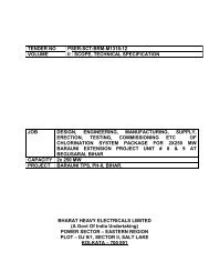
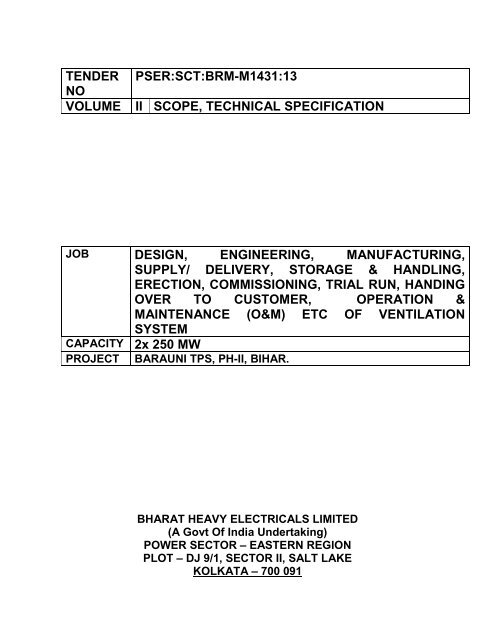
TENDER<br />
NO<br />
VOLUME<br />
PSER:SCT:BRM-M1431:13<br />
<strong>II</strong> SCOPE, TECHNICAL SPECIFICATION<br />
JOB DESIGN, ENGINEERING, MANUFACTURING,<br />
SUPPLY/ DELIVERY, STORAGE & HANDLING,<br />
ERECTION, COMMISSIONING, TRIAL RUN, HANDING<br />
OVER TO CUSTOMER, OPERATION &<br />
MAINTENANCE (O&M) ETC OF VENTILATION<br />
SYSTEM<br />
CAPACITY 2x 250 MW<br />
PROJECT BARAUNI TPS, PH-<strong>II</strong>, BIHAR.<br />
BHARAT HEAVY ELECTRICALS LIMITED<br />
(A Govt Of India Undertaking)<br />
POWER SECTOR – EASTERN REGION<br />
PLOT – DJ 9/1, SECTOR <strong>II</strong>, SALT LAKE<br />
KOLKATA – 700 091
BIHAR STATE ELECTRICITY BOARD<br />
2X250 MW BARAUNI TPS<br />
UNIT # 8 & 9<br />
VOLUME - <strong>II</strong>B & <strong>II</strong>I<br />
TECHNICAL SPECIFICATION<br />
FOR<br />
VENTILATION SYSTEM<br />
SPECIFICATION NO.: - PE-TS-374-554-A001<br />
REV. - 0<br />
OCTOBER 2011<br />
BHARAT HEAVY ELECTRICALS LIMITED<br />
POWER SECTOR<br />
PROJECT ENGINEERING MANAGEMENT<br />
PROJECT ENGIEERING INSTITUTE BUILDING<br />
SECTOR-16A, PLOT NO.-25, NOIDA, INDIA
TITLE 2 x 250 MW BARAUNI TPS SPECIFICATION NO. PE-TS-374-554-A001<br />
INDEX<br />
VENTILATION SYSTEM<br />
VOLUME<br />
SECTION<br />
REV 00 DATE 25.10.2011<br />
SHEET 1 OF 2<br />
VOLUME – <strong>II</strong>B<br />
SECTIONS TITLE SPECIFICATION NO. No. of<br />
Sheets<br />
SECTION-A INTENT OF SPECIFICATIONS PE-TS-374-554-A001 1<br />
SECTION-B PROJECT INFORMATION 2<br />
SECTION-C<br />
SPECIFIC TECHNICAL<br />
REQUIREMENT<br />
TECHNICAL SPECIFICATION<br />
(ELECTRICAL PORTION)<br />
TECHNICAL SPECIFICATION<br />
( C & I PORTION)<br />
ANNEXURES<br />
PE-TS-374-554-A001 15<br />
24<br />
47<br />
i) ANNEXURE-I LIST OF MAKES 3<br />
SECTION-D STANDARD TECHNICAL<br />
SPECIFICATIONS<br />
1. Air Washer PES-554-12 Rev 01 3<br />
Data Sheet-A<br />
PE-TS-374-554-A001 2<br />
Rev0<br />
Data Sheet-C PES-554-12 Rev 01 1<br />
2. Ventilation Fans PES-553-11 Rev02 4<br />
Data Sheet-A Centrigugal PE-TS-374-554-A001 3<br />
fan<br />
Data Sheet-A RE unit PE-TS-374-554-A001 2<br />
3. Low pressure air distribution PES-553-07 Rev 02 6<br />
system<br />
Data Sheet-A<br />
PE-TS-374-554-A001 1<br />
Rev0<br />
Data Sheet-C PES-553-04 Rev 01 1<br />
4. Centrifugal pump PES-554-02-1Rev 01 7<br />
Data Sheet-A<br />
PE-TS-374-554-A001 2<br />
Rev0<br />
Data Sheet-C PES-554-02-1Rev 01 1<br />
5. Filter PES-553-04 Rev 02 3<br />
Data Sheet-A<br />
PE-TS-374-554-A001 1<br />
Rev0<br />
Data Sheet-C PES-553-04 Rev 01 1<br />
6. Insulation PES-553-08 Rev 01 4<br />
Data Sheet-A<br />
PE-TS-374-554-A001 1<br />
Rev0<br />
Data Sheet-C PES-554-13 Rev 01 1<br />
SECTION-E INSPECTION AND TESTING 3
TITLE 2 x 250 MW BARAUNI TPS SPECIFICATION NO. PE-TS-374-554-A001<br />
INDEX<br />
VENTILATION SYSTEM<br />
VOLUME<br />
SECTION<br />
REV 00 DATE 25.10.2011<br />
SHEET 2 OF 2<br />
VOLUME-<strong>II</strong>I<br />
(Data sheet-B and schedules to be furnished by each Bidder along with the Technical Bid.)<br />
SECTIONS TITLE SPECIFICATION NO.<br />
1. Data sheet B for ventilation fans PE-TS-374-554-A001<br />
2. Data sheet B for Low Pressure air Distribution PE-TS-374-554-A001<br />
System<br />
3. Data sheet B for Air Filter PE-TS-374-554-A001<br />
4. Data sheet B for Centrifugal pump PE-TS-374-554-A001<br />
5. Deviation Sheet Part B<br />
6. Deviation Sheet Part C<br />
LIST OF DRGS./ ENCLOSURES<br />
1. TYPICAL SCHEME OF AIR WASHER SYSTEM PE-DG-374-554-A002 R0.<br />
2. TYPICAL SCHEME OF UAF PE-DG-374-554-A003 R0.<br />
3. MAKE UP WATER SCHEME PE-DG-374-554-A005 R0.<br />
4. MAIN EQUIPMENT PLANT LAYOUT PE-DG-374-100-M002 R1.<br />
5. TG HALL EQPT. LAYOUT PLAN AT 0.0 M PE-DG-374-100-M003 R1<br />
6. TG HALL EQPT. LAYOUT PLAN AT 8.5 M PE-DG-374-100-M004 R1<br />
7. TG HALL EQPT. LAYOUT PLAN AT 13.5 M PE-DG-374-100-M005 R1<br />
8. EQPT. LAYOUT PLAN AT 19.0 M & 25.5M (BC PE-DG-374-100-M006 R1<br />
BAY)<br />
9. MAIN PLANT CROSS-SECTION PE-DG-374-100-M007 R1
PEM-6666-0<br />
TITLE SPECIFICATION NO. PE-TS-374-554—A001<br />
2 X 250 MW BARAUNI TPS VOLUME-<strong>II</strong> B<br />
SECTION - A<br />
VENTILATION SYSTEM<br />
INTENT OF SPECIFICATION REV 0 DATE<br />
SHEET 1 OF 1<br />
1.0 Intent of Specification<br />
1.1 This specification covers proper design, fabrication, manufacture, inspection and testing at<br />
manufacturer’s works or at sub vendor’s works, proper packing, transportation to site, freight<br />
and insurance, storage and handling at site, erection and commissioning including trial run<br />
at site for VENTILATION SYSTEM for complete Power plant as per different section of<br />
technical specification for 2 X 250 MW BARAUNI TPS in BEGUSARAI, BIHAR.<br />
1.2 It is not the intent to specify completely herein all details of design and construction of<br />
equipment. However, all the equipments shall conform in all respect to high standards of<br />
engineering, design, workmanship and be capable of performing in continuous commercial<br />
operation up to desired period.<br />
1.3 The general terms and conditions, instructions to bidder and other attachments referred to<br />
else where are made a part of the tender specification. The equipment, materials and works<br />
covered by this specification are subject to all the attachments referred in the specification.<br />
The bidder shall be responsible for and governed by all the requirements stipulated<br />
hereinafter.<br />
1.4 No deviation is permitted in normal case. Deviation if any shall be clearly brought out<br />
otherwise it will be presumed that the bidder’s offer is in line with what has been<br />
stated/asked in this NIT specification.<br />
1.5 In the event of any conflict between the requirements of two clauses of this specification<br />
documents or requirements of different codes and standards specified, the more stringent<br />
requirement as per the interpretation of the owner shall apply.<br />
1.6 It is not the intent to completely specify all details of design and construction herein.<br />
Nevertheless, the equipment and installation shall conform to high standard of engineering,<br />
design and workmanship in all respects and shall be capable of performing in continuous<br />
satisfactory commercial operation in a manner acceptable to the Purchaser.<br />
1.7 The purchaser reserves the right to place separate order for any of the specified items<br />
without assigning any reason whatsoever. The decision of the purchaser in this regard will be<br />
final.
Project Information<br />
2x250 MW Barauni Unit# 8 &9<br />
1.0.0 PROJECT INFORMATION<br />
1. Owner Bihar Electricity Board (BSEB).<br />
2. Project 2 X 250 MW Unit # 8 & 9, Barauni-TPS, Begusarai<br />
3. Owner’s consultant M/s Evonik, Sec-16, Noida<br />
4. Location Town: Barauni, District: Begusarai, State: Bihar<br />
5. Site Existing ash dyke are of about 340 acres<br />
6. FFL/FGL FFL EL+/- 0.0 corresponds to RL 45.50 M above MSL<br />
FGL corresponds to RL 45.00 M above MSL<br />
7. Nearest Airport Patna-115 Kms.<br />
8. Nearest Rail Head Simaria Railway Station on North Eastern railways<br />
9. Access to site The site is at Barauni-Mokama section of National Highway (NH-<br />
31)<br />
10. Metrological data (Refer as under)<br />
Site Meteorological Data:<br />
S.NO. DESCRIPTION DATA<br />
A Latitude N 25 0 23’13.5” to N 25 0 23’54”<br />
B Longitude E 86 0 01’05.1” to E 86 0 01’46.3”<br />
1. Maximum Ambient Air Temperature 35.2° C<br />
2. Minimum Ambient Air Temperature 11.4°C<br />
Dry Bulb Temperatures<br />
Highest recorded :<br />
35.3°.C<br />
Lowest recorded :<br />
12.1° C<br />
Wet Bulb Temperatures<br />
1. Design AMB WBT Minimum – 12.0°.C<br />
Maximum- 29.0°.C<br />
C RELATIVE HUMIDITY<br />
Design AMB WBT Minimum- 26%<br />
Maximum- 98%<br />
Annual Mean 52 %<br />
D RAINFALL<br />
1. Annual Total 1003.4 mm<br />
E WIND DATA<br />
1. Wind Speed 47 m/sec<br />
2. Prevailing Wind Direction East (blowing from)<br />
3. Wind Pressure Minimum 990 hPa.<br />
Maximum 1011.5 hPa.<br />
F SEISMIC COEFFICIENT Zone IV as per IS-1893 Part-I (2002)<br />
Page 1 of 1
Project Information<br />
2x250 MW Barauni Unit# 8 &9<br />
Table 2.3: Coal Analysis<br />
S.No. Parameters Worst Coal Designed Coal<br />
Proximate Analysis (%)<br />
1 Fixed Carbon (FC) % 29.4 29.7<br />
2 Volatile Matter(VM) % 17.7 20.6<br />
3 Moisture % 10.0 8.0<br />
4 Ash% 42.9 41.7<br />
Ultimate Analysis (% by weight)<br />
1 Carbon % 37.66 40.3<br />
2 Hydrogen % 4.08 4.47<br />
3 Sulphur % 0.3 ‐<br />
4 Nitrogen % 1.8 1.89<br />
5 Oxygen (by diff) % 3.26 3.64<br />
6 Moisture % 10 8<br />
7 Ash 42.9 41.7<br />
8 GCV, Kcal/kg 3100 3300<br />
9 Grindability Index (HGI) 55.0 50.0<br />
10 Ash Fusion Temperature 1350 1350<br />
Page 2 of 1
TECHNICAL SPECIFICATION<br />
VENTILATION SYSTEM<br />
2X250 MW BARAUNI TPS, UNIT # 8 & 9<br />
SPECIFICATION NO.PE-TS-374-554-A001<br />
VOLUME <strong>II</strong> B<br />
SECTION - C<br />
REV. 0 DATE NOVEMBER 2011.<br />
SHEET 1 OF 15<br />
SECTION-C<br />
SPECIFIC TECHNICAL REQUIREMENTS
TECHNICAL SPECIFICATION<br />
VENTILATION SYSTEM<br />
2X250 MW BARAUNI TPS, UNIT # 8 & 9<br />
SPECIFICATION NO.PE-TS-374-554-A001<br />
VOLUME <strong>II</strong> B<br />
SECTION - C<br />
REV. 0 DATE NOVEMBER 2011.<br />
SHEET 2 OF 15<br />
1. INTENT<br />
1.1.1 The purpose of this document is to bring out clarity with regard to the following:<br />
a) System description and Basic operation & Control Philosophy<br />
b) Major technical requirements of various items covered under this package<br />
c) Scope, terminal points, exclusion<br />
d) Layout requirement<br />
2. CODES AND STANDARD<br />
2.1.1 All equipment, system and works covered under this specification shall comply with<br />
all currently applicable statutes, regulations and safety codes in the locality where the<br />
equipment will be installed. Also, all equipment shall conform to the latest applicable<br />
Indian or International Standards established to be equivalent or superior to the<br />
Codes and Standards specified in Section-D and listed below. In case the BIDDER<br />
offers equipment conforming to any standards other than those specified in<br />
component specifications, the BIDDER shall furnish copies of standards translated in<br />
English while submitting his proposal.<br />
2.1.2 IS 277: Galvanised Steel Sheets<br />
2.1.3 IS 325: Three phase induction motors<br />
2.1.4 IS 655: Metal Air ducts<br />
2.1.5 IS 7613: Method of testing panel type air-filters for air-conditioning and Ventilation<br />
system.<br />
2.1.6 IS 3588: Electric axial fans<br />
2.1.7 IS 4894: Centrifugal fans<br />
2.1.8 UL 555: Fire dampers<br />
3. SYSTEM DESCRIPTION<br />
3.1.1 Evaporative cooling system by adapting Air washer units (AWU) shall be provided for<br />
the ventilation of various floors of Turbine hall, B-C bay switch gear room and cable<br />
gallery of Turbine building. The cooled & humidified air from air washer unit is<br />
distributed by means of Galvanised sheet steel ducting to the TG building comprising<br />
ground, mezzanine, operating floor and near various heat sources like Turbo<br />
generator, Condenser, Boiler feed pumps, HP and LP heaters etc. In this system<br />
fresh filtered air is drawn through air washers & evaporative cooled before being<br />
supplied to the supply air distribution system. The filtered air while passing through air<br />
washers could be cooled & humidified.<br />
3.1.2 The hot air from the TG hall shall be exhausted by means of roof extractors.<br />
3.1.3 The quantity of air exhausted is kept lower than the quantity of air supplied so that a<br />
little over pressure is maintained inside the TG hall.<br />
3.1.4 With this system the dry bulb temperature within the turbine building shall be<br />
maintained at a temperature not exceeding 38C at all times of the year.<br />
3.1.5 Fire dampers (motor operated) shall be provided in the supply air ducting leading to<br />
all electrical rooms. The operation of these automatic fire dampers shall be<br />
interlocked with the fire alarm system & the operation of these dampers shall also be<br />
possible from the control panel remote manually and automatic fire damper shall<br />
have fire rating of minimum 120 minutes.<br />
3.1.6 For Auxiliary Buildings in various location dry ventilation with supply and / or exhaust<br />
fan is provided. Details of the types of ventilation for each area are furnished in<br />
Clause 4.1.2.
TECHNICAL SPECIFICATION<br />
VENTILATION SYSTEM<br />
2X250 MW BARAUNI TPS, UNIT # 8 & 9<br />
SPECIFICATION NO.PE-TS-374-554-A001<br />
VOLUME <strong>II</strong> B<br />
SECTION - C<br />
REV. 0 DATE NOVEMBER 2011.<br />
SHEET 3 OF 15<br />
3.1.7 Washed & filtered air is supplied from unitary air filtration unit (UAF) to non-AC areas<br />
of ESP & VFD control building like switchgear rooms, cable spreader rooms,MCC<br />
room etc.<br />
4. DESIGN CRITERIA:<br />
4.1 SYSTEM DESIGN CRITERIA:<br />
4.1.1 The outside design conditions considered are as follows:<br />
Summer Monsoon Winter<br />
DBT (°C) 40.7 33.9 8.0<br />
WBT (°C) 23.4 29.0 7.6<br />
4.1.2 The inside design conditions:-<br />
S.No. Area Inside Condition Type of<br />
Ventilation<br />
1. TG Hall & Cable<br />
Spreader room<br />
2. Electrical Rooms<br />
(M.C.C. room,<br />
Switchgear room<br />
in TG Building)<br />
3. All toilets,<br />
pantries.<br />
4. Battery and<br />
battery charger<br />
room<br />
5. Elevator Machine<br />
room<br />
6. Non AC areas of<br />
ESP control<br />
(MCC/switch gear<br />
room )<br />
7. Non AC areas of<br />
ESP control (cable<br />
spreader rooms)<br />
Inside temperature not<br />
exceeding 38C dry bulb<br />
temperatures at all times of<br />
the year.<br />
Inside temperature not<br />
exceeding 38C dry bulb<br />
temperatures at all times of<br />
the year.<br />
Inside temperature not<br />
exceeding 3C above<br />
outside dry bulb<br />
temperature.<br />
Inside temperature not<br />
exceeding 3C above<br />
outside dry bulb<br />
temperature.<br />
Inside temperature not<br />
exceeding 3C above<br />
outside dry bulb<br />
temperature.<br />
Inside temperature not<br />
exceeding 38C dry bulb<br />
temperatures at all times of<br />
the year.<br />
Inside temperature not<br />
exceeding 38C dry bulb<br />
temperatures at all times of<br />
the year.<br />
8. Pump Houses Inside temperature not<br />
exceeding 3C above<br />
outside dry bulb<br />
temperature.<br />
9. Electrical rooms<br />
for all Auxiliary<br />
Inside temperature not<br />
exceeding 3C above<br />
Ventilation with Air<br />
washer &<br />
mechanical<br />
exhaust from roof<br />
extractor units.<br />
Ventilation with Air<br />
washer & exhaust<br />
through gravity<br />
damper.<br />
Mechanical<br />
ventilation with<br />
propeller type<br />
exhaust fan.<br />
Negative<br />
pressurization of 5<br />
mm by means of<br />
axial flow exhaust<br />
fans with<br />
flameproof motors.<br />
Supply air through<br />
axial fan filter unit<br />
and exhaust<br />
through gravity<br />
damper.<br />
Ventilation with<br />
UAF & exhaust<br />
through gravity<br />
damper.<br />
Ventilation with<br />
UAF & exhaust<br />
through gravity<br />
damper.<br />
Mechanical<br />
Exhaust by means<br />
of axial flow<br />
exhaust fans / RE<br />
Unit.<br />
Supply air through<br />
axial fan filter unit<br />
ACPH<br />
6 to 8<br />
10<br />
20<br />
30<br />
15<br />
10<br />
6 to 8<br />
20<br />
20
TECHNICAL SPECIFICATION<br />
VENTILATION SYSTEM<br />
2X250 MW BARAUNI TPS, UNIT # 8 & 9<br />
SPECIFICATION NO.PE-TS-374-554-A001<br />
VOLUME <strong>II</strong> B<br />
SECTION - C<br />
REV. 0 DATE NOVEMBER 2011.<br />
SHEET 4 OF 15<br />
Buildings, i.e.,<br />
associated with<br />
pump houses etc.<br />
10. Compressor<br />
House<br />
outside dry bulb<br />
temperature.<br />
Inside temperature not<br />
exceeding 3C above<br />
outside dry bulb<br />
temperature.<br />
11. DG House Inside temperature not<br />
exceeding 3C above<br />
outside dry bulb<br />
temperature.<br />
12. AC plant room Inside temperature not<br />
exceeding 3C above<br />
outside dry bulb<br />
temperature.<br />
13. Work Shop Inside temperature not<br />
exceeding 3C above<br />
outside dry bulb<br />
temperature.<br />
14. Waterv treatment<br />
plant building (as<br />
applicable)<br />
Inside temperature not<br />
exceeding 3C above<br />
outside dry bulb<br />
temperature.<br />
and exhaust<br />
through gravity<br />
damper.<br />
Supply air through<br />
axial fan filter unit<br />
and exhaust<br />
through axial<br />
exhaust fan.<br />
Mechanical<br />
exhaust by means<br />
of axial flow<br />
exhaust fans<br />
Mechanical<br />
exhaust by means<br />
of axial flow<br />
exhaust fans<br />
Mechanical<br />
exhaust by means<br />
of axial flow<br />
exhaust fans<br />
Mechanical<br />
exhaust by means<br />
of axial flow<br />
exhaust fans<br />
15<br />
25<br />
15<br />
15<br />
15<br />
Note: For ventilation (DRY) System of auxiliary building the ambient mechanical<br />
ventilation system shall be designed to maintain dry bulb temperature not exceeding 3<br />
deg C above ambient dry bulb temperature or based on number of air changes per<br />
hour, which ever results in high air flow rate.<br />
4.1.3 All ventilation equipment's shall be designed for continuous duty & shall operate on<br />
100% fresh air basis.<br />
4.1.4 The ducting shall be sized to have constant friction drop along its length with air<br />
velocity in the ducts normally not exceeding 12 m/sec for ventilation system.<br />
4.1.5 The air washer shall be designed for 90% saturation efficiency.<br />
4.1.6 Efficiency of UAF shall be 70%.<br />
4.1.7 Circulating water capacity for air washer units shall be minimum 1 m3/hr per 1000<br />
m3/hr of air flow while for UAF unit, it shall be minimum 0.6 m3/hr per 1000 m3/hr of<br />
air flow.<br />
5. LAYOUT CONSIDERATIONS<br />
5.1.1 For each Unit 4 nos. Containerised Air Washer Units of capacity 1,30,000 CMH each<br />
are provided. 2 nos. are placed in AB-bay at roof of TG hall of and 2nos. are placed<br />
in BC bay at 25.5M level. Hence for two Units total 8 nos. Air Washer units are<br />
provided.<br />
5.1.2 One (1 no.) UAF (1 x 100%) of 50,000 CMH capacity at 60 mmwc will be provided for<br />
ESP Building of Unit-1 and One (1 no.) UAF (1 x 100%) of 50,000 CMH capacity at<br />
60 mmwc will be provided for ESP Building of Unit-2 and would be located at the roof<br />
of ESP control building.<br />
5.1.3 9 nos. of R.E. units of capacity 40,000 CMH at 15 mmwc each is provided for each<br />
Unit, i.e., 18 nos. for two units mounted on TG hall roof for exhausting the hot &<br />
vitiated air from TG hall. The hot air from cable gallery & switchgear room is taken to<br />
TG hall through gravity dampers.
TECHNICAL SPECIFICATION<br />
VENTILATION SYSTEM<br />
2X250 MW BARAUNI TPS, UNIT # 8 & 9<br />
SPECIFICATION NO.PE-TS-374-554-A001<br />
VOLUME <strong>II</strong> B<br />
SECTION - C<br />
REV. 0 DATE NOVEMBER 2011.<br />
SHEET 5 OF 15<br />
6. EQUIPMENT AND SERVICES TO BE PROVIDED FOR VENTILATION SYSTEM:<br />
6.1 AIR WASHER<br />
6.1.1 Each Air Washer capacity is 1,30,000 CMH and is of double skin sheet metal<br />
containerised type suitable for placement in open area. No separate building / room is<br />
required for the placement of these units. Each air washer comprises of:<br />
6.1.2 Each packaged evaporative coolers shall consists of louvers, pre-filters, air<br />
distribution plates, spray systems, drift eliminators with flooding nozzles, centrifugal<br />
fans located in an sheet metal enclosure with adequate reinforcement. The units shall<br />
be mounted on the outside wall with suitable supporting framework. The unit shall<br />
have an access door for filter, nozzles, pump and fan maintenance.<br />
6.1.3 Double skin panels (inside and outside) shall be fabricated using minimum 0.6 mm<br />
(24 G) galvanized steel, with 25 mm thick polyurethane insulation in between, GSS<br />
channels shall be used as reinforcing to give structural strength. Outside skin shall be<br />
pre plasticised & inside sheet shall be plain GI. Air Washer tank shall be made of<br />
6mm thick MS with epoxy coating. Suitable number of brass screen shall be provided<br />
in the air washer tank to arrest the dirt entering the circulation pump suction. Suction<br />
screen shall be 24 G brass.<br />
6.1.4 Filter sections complete with HDPE filters and efficiency 90% down to 20 microns and<br />
maximum face velocity of 1.75 m/ sec. Inlet louvers and bird screen as applicable.<br />
6.1.5 A spray nozzle system consisting of two banks spray system each connected to<br />
individual headers, louvers, pre filters, air distribution plates, drift eliminators with<br />
flooding nozzles, suction screen, Drain valve, Over flow valve float valve, quick fill<br />
connection with globe valve, make up connection, flow regulating valves for<br />
controlling flow to spray header. Nozzles shall be of Bronze (with chrome plating) /<br />
Brass, pressure across nozzle shall be 1.4 -2.4 Kg. / sq.cm.<br />
6.1.6 Moisture eliminator section.<br />
6.1.7 Fan section complete with backward curved DIDW centrifugal fan mounted on a shaft<br />
with adjustable motor base.<br />
6.1.8 One No. adequately sized TEFC sq. cage induction motor suitable for 415 V, 3<br />
phase, 50 Hz AC supply with drive package comprising fan pulley, motor pulley, V-<br />
belt and belt guard.<br />
6.1.9 Drain piping from the Air Washer up to nearest drain point.<br />
6.1.10 Lot – Controls comprising:<br />
6.1.10.1. Sump level high / low switch for automatic start / stop of pump.<br />
6.1.11 Lot – Serrated rubber pads for vibration isolation<br />
6.1.12 Two (2) nos. (2 x 100 % duty) Back pull out / Horizontal Split Casing type centrifugal<br />
pumps for circulation of water shall be considered. Pump suction shall be provided<br />
with pot strainer with by-pass valves, inlet and outlet pressure gauge. These pumps<br />
are located outside the air washer container.<br />
Ambient air shall be drawn into the air washer unit by the centrifugal fan. Inside the<br />
unit, the air shall pass through the dry panel filter and shall be cooled by evaporative<br />
cooling process (by passing air through spray chamber) and the cooled air shall pass<br />
through the moisture eliminator set & shall be distributed within the service space<br />
thru’ ducts. The hot air from the service space shall be exhausted out through wall /<br />
roof mounted axial flow fans / gravity dampers. The capacity of the exhaust fans<br />
shall be selected so as to maintain a slight positive pressure inside w.r.t. outside. The<br />
capacity of the Roof Exhauster unit shall be selected such that approx. 60% - 70% of<br />
supplied air shall be exhausted.
TECHNICAL SPECIFICATION<br />
VENTILATION SYSTEM<br />
2X250 MW BARAUNI TPS, UNIT # 8 & 9<br />
SPECIFICATION NO.PE-TS-374-554-A001<br />
VOLUME <strong>II</strong> B<br />
SECTION - C<br />
REV. 0 DATE NOVEMBER 2011.<br />
SHEET 6 OF 15<br />
6.2 UAF<br />
6.2.1 Each UAF capacity is 50,000 CMH at 60 mmwc and is of sheet metal type suitable for<br />
placement in open area. No separate building / room is required for the placement of<br />
these units. Each UAF comprises of:<br />
6.2.2 One (1) No. (100% duty) Centrifugal fan backward inclined, SISW type, complete with<br />
electric drive motor, drive Pulleys, V-belt, belt guards, slide rails and other<br />
accessories etc.<br />
6.2.3 Two (2) Nos. (2 x100 % duty) Centrifugal mono-bloc pumps for circulation of water.<br />
Pump system shall be provided with pot strainer with by-pass valves, inlet and outlet<br />
pressure gauge & valves, these pumps are located outside the air washer container &<br />
coarse strainer shall be provided at the outlet of the tank.<br />
6.2.4 A spray nozzle system consisting of single bank spray system connected to header,<br />
Sump complete with makeup connection, overflow connection, drain connection &<br />
water level switch.flow regulating valves for controlling flow to spray header. Nozzles<br />
shall be of Bronze (with chrome plating) / Brass.<br />
6.2.5 Distribution plate and moisture eliminators.<br />
6.2.6 UAF chamber of sheet metal construction with MS tank etc.<br />
6.2.7 Intake louver with frame & screen.<br />
6.2.8 Water repellent type nylon filter complete with fixing frame.<br />
6.2.9 All valves, pipes, nuts & bolts, pipe hangers, supports, internal fittings and supports<br />
including ball float valves for makeup water connection.<br />
6.2.10 Inspection door with ladder and cat walk in the spray chamber.<br />
6.2.11 Drain pipe with siphon, marine light in each section.<br />
6.2.12 Air filters complete with fixing frame.<br />
6.2.13 Sump complete with makeup connection, overflow connection, drain connection &<br />
water level switch.<br />
6.3 CENTRIFUGAL FLOW FAN UNITS<br />
6.3.1 Each centrifugal fan is complete with<br />
6.3.2 Fan impeller (backward curved) with casing & supports.<br />
6.3.3 Electric drive motor. Fan rpm not exceeding 1000rpm and all motor shall be EEF-1 as<br />
per 12615-2004.<br />
6.3.4 Drive Pulleys, V-belt, belt guards, slide rails etc.<br />
6.3.5 Dampers and flexible connection with matching flanges.<br />
6.3.6 Vibration isolators, foundation bolts and nuts. Fan o/l velocity not exceeding 12 m/s.<br />
6.3.7 <strong>Volume</strong> control Damper at the Fan outlet.<br />
6.3.8 Common base frame with spring type vibration isolators.<br />
6.3.9 For fans and blowers continuous motor rating (at 50 Deg.C ambient).<br />
6.3.10 For belt drives the belts shall be sized for 150% of the rated power and their shall be<br />
minimum of two belts per drive.<br />
6.4 WALL MOUNTED AXIAL FLOW FAN / RE UNIT<br />
Each wall mounted axial flow fan is complete with
TECHNICAL SPECIFICATION<br />
VENTILATION SYSTEM<br />
2X250 MW BARAUNI TPS, UNIT # 8 & 9<br />
SPECIFICATION NO.PE-TS-374-554-A001<br />
VOLUME <strong>II</strong> B<br />
SECTION - C<br />
REV. 0 DATE NOVEMBER 2011.<br />
SHEET 7 OF 15<br />
6.4.1 Fan impeller with aerofoil section of cast aluminium alloy & casing/short duct as<br />
required, static & dynamic balancing of impeller.<br />
6.4.2 The speed of fans shall not exceed 960 rpm for fan with impeller diameter above 450<br />
mm and 1400 rpm for fan with impeller diameter 450 mm or less. However for fans<br />
having static pressure of 30 mm WC or above the speed of the fan shall not exceed<br />
1500 rpm for fan with impeller diameter of above 450mm and 2800 rpm for with<br />
impeller diameter of 450 mm or less. The first critical speed of rotating assembly shall<br />
be at least 25% above the operating speed.<br />
6.4.3 Electric drive motor with coupling if any, including motor brackets.<br />
6.4.4 Inlet cone and grouting framework, if any.<br />
6.4.5 Rain protection cowl with bird-screen adjustable damper, vibration isolators, back<br />
draft dampers, filters, supporting arrangement etc. Shall be provided.<br />
6.4.6 Each axial fan comprises of fan, fan motor, i/l & o/l cone (for tube axial), louvered<br />
shutter (exhaust fans) & supporting arrangement.<br />
6.5 ALL SUPPLY / EXHAUST AIR DUCTING<br />
6.5.1 Air distribution from Air Washers and UAF would be done through ducting system,<br />
grilles and diffusers. Ducts shall be made of GI sheets of class 180 as per IS: 277<br />
(i.e., having Zinc coating 200 gm/ m 2 ). The air velocity in the ducts shall not normally<br />
exceed 12 m/sec. for ventilation system. However the air velocity shall be increased<br />
more than 12 m/sec up to 15 m/s., in case of layout constraint to clear the duct. All<br />
ducting shall be designed on equal friction method and fabricated as per IS: 655.<br />
6.5.2 The material thickness of the ducting will be as following considering the industrial<br />
duty conditions<br />
6.5.3 Thickness of rectangle ducts shall be as follows:<br />
Larger Dimension of Ducts<br />
(mm)<br />
Up to 750<br />
Thickness of GI Sheet (mm)<br />
0.63 (24G)<br />
751 to 1500 0.80 (22G)<br />
1501 to 2250 1.00 (20G)<br />
2251 to above 1.25 (18G)<br />
6.5.4 For Battery room areas, where exhaust ducting is required for ventilation, MS ducting<br />
with epoxy painting or fibre glass ducting shall be provided. Further, due to layout<br />
constraint if ventilation duct is required to pass through battery room, then MS ducting<br />
with epoxy paint will be provided for the duct portion inside the battery room.<br />
6.5.5 The diffuser / grills shall be provided as per requirement and shall be powder coated<br />
ms construction for ventilation system.<br />
6.5.6 <strong>Volume</strong> control dampers, guide vane, splitter dampers shall be provided as required.<br />
6.5.7 Supports and hangers including anchor bolts shall be provided as required.<br />
6.5.8 Manually adjustable/back draft type/Gravity type exhaust air dampers shall be<br />
provided as required.<br />
6.5.9 All exposed duct work to the outside shall be provided with Thermal insulation.<br />
Surface preparation & painting to be done before applying insulation.
TECHNICAL SPECIFICATION<br />
VENTILATION SYSTEM<br />
2X250 MW BARAUNI TPS, UNIT # 8 & 9<br />
SPECIFICATION NO.PE-TS-374-554-A001<br />
VOLUME <strong>II</strong> B<br />
SECTION - C<br />
REV. 0 DATE NOVEMBER 2011.<br />
SHEET 8 OF 15<br />
6.6 INSULATION<br />
6.6.1 Thermal insulation shall be provided for the duct exposed to sun / rain only.<br />
6.6.2 Thermal insulation shall be 25mm thick resin bounded fibre glass wool of density 32<br />
kg/m3 with 24G Al cladding.<br />
6.6.2.1. Thermal insulation of the Ventilation duct shall be provided with Finish F-4 which is<br />
elaborated as under:<br />
Step-1: Wrapping of Poly-Bonded Hessain (PBH- to act aas vapour seal) on outer<br />
surface of insulation with 50mm overlap stitching and sealing of overlap with synthetic<br />
adhesive like CPRX or equivalent compound.<br />
Step-2: The surface then shall be wrapped with 19 mm mesh 24 SWG GI wire<br />
netting, butting all the joints and laced down with 22 SWG lacing wire.<br />
Step-3: Sand cement (4:1) plaster shall be applied in two layers totalling to 12.5 mm<br />
thick, te second layer being brought to a smooth finish. A water proofing compound<br />
shall be added to the cement before its application.<br />
Step-4: Application of 3 mm thick coat proofing compound “SHALIKOTE 30” or<br />
equivalent and wrapped with fibre glass RP tissue followed by final coat of 3 mm thick<br />
proofing compound “SHALIKOTE 30” or equivalent over the RP tissue.<br />
6.7 WATER PUMP SETS<br />
6.7.1 Each circulating water pump set for air washer shall comprise of the following<br />
6.7.2 Back pull out / Horizontal Split Casing centrifugal pump of adequate capacity to<br />
match the system requirement for air washer & Back pull out / Split Casing<br />
Centrifugal Pump of adequate capacity to match the system requirement for UAF.<br />
6.7.3 One no. adequately sized TEFC sq. cage induction motor suitable for 415V, 3 phase,<br />
50 Hz AC supply.<br />
6.7.4 One no. Pot type strainer at inlet complete with screen, drain arrangement etc.<br />
6.7.5 150 mm dia. Dial Type pressure gauges one each at suction & discharge side of the<br />
pump set.<br />
6.7.6 Gate valve, one each at suction and Globe valve, one each at discharge side of the<br />
pump set.<br />
6.7.7 One no. non-return (check) valve at discharge side of pump set.<br />
6.7.8 For pumps continuous motor rating ( at 50 Deg.C ambient) shall be at least ten<br />
percent ( 10%) above the max. load demand of the pump in the entire operation<br />
range.<br />
7. CONTROL PHILOSOPHY:<br />
7.1 VENTILATION FAN MOTORS<br />
7.1.1 All ventilation 3 phase fan motors except Air Washer / UAF Units shall be controlled<br />
from Local Starter Panel.<br />
7.1.2 All 240V, 1ph fans (up to 0.25KW motor rating and below ratings) will be operated by<br />
Switches located near the individual fans.<br />
7.2 AIR WASHER / UAF UNITS<br />
7.2.1 Each Air Washer/ system will have one LCP with IP-65 protection located near each<br />
Air Washer/ Unitary Air Filtration unit for it’s control.<br />
7.2.2 AWU/UAF SUMP WATER LEVEL CONTROL
TECHNICAL SPECIFICATION<br />
VENTILATION SYSTEM<br />
2X250 MW BARAUNI TPS, UNIT # 8 & 9<br />
SPECIFICATION NO.PE-TS-374-554-A001<br />
VOLUME <strong>II</strong> B<br />
SECTION - C<br />
REV. 0 DATE NOVEMBER 2011.<br />
SHEET 9 OF 15<br />
7.2.2.1. The water sump of each Air Washer Unit and UAF unit shall be provided with a low<br />
level switch which will initiate an alarm & will stop the pump, in case water level falls<br />
below a pre-determined mark.<br />
7.2.3 Following indications are to be provided for Air Washers and UAF Units in the<br />
respective Local Starter Cum Control Panel:<br />
7.2.3.1. Fan Running.<br />
7.2.3.2. Fan Stop.<br />
7.2.3.3. Pump – 1 Running (For Spray Set Arrangement).<br />
7.2.3.4. Pump – 1 Stop (For Spray Set Arrangement).<br />
7.2.3.5. Pump – 2 Running (For Spray Set Arrangement).<br />
7.2.3.6. Pump – 2 Stop (For Spray Set Arrangement).<br />
7.2.3.7. Fan Motor over Load Trip.<br />
7.2.3.8. Pump - 1 Motor Over Load Trip.<br />
7.2.3.9. Pump - 2 Motors Over Load Trip.<br />
7.2.3.10. Sump Water Level Low.<br />
7.2.4 Provision of alarm (audio-visual) for Trip of any motor & low water level in the sump<br />
shall also be kept in the Local Control Panel.<br />
7.2.5 ELECTRICAL TYPE FIRE DAMPERS<br />
7.2.6 Motorized type electrically operated Fire Dampers in the ventilation supply air ducting<br />
/ fans leading to electrical rooms like various MCC Rooms, Switchgear Rooms, Cable<br />
Spreader Rooms. These dampers shall be operated with the help of signal from<br />
smoke detectors / thermal sensors. Motors shall remain energized in normal condition<br />
to effect opening of dampers. In the event of fire, the motors will be de-energized and<br />
the damper will close due to spring action.<br />
7.2.6.1. In case of fire, all the motorized fire dampers provided in the supply air duct will<br />
close and the relevant fan motors will be tripped at the same time. The signals for<br />
this operation will come from fire alarm panel.<br />
7.2.6.2. In case of fire in the TG Hall or in the electrical rooms. All the supply fans of AWUs<br />
shall be stopped automatically with the sense from Smoke detectors through fire<br />
panels.<br />
8. SPECIFIC REQUIREMENTS<br />
8.1.1 The system shall guarantee to maintain specified inside design conditions.<br />
8.1.2 The air washer shall have minimum 90% saturation efficiency and UAF shall have<br />
minimum 70% saturation efficiency.<br />
8.1.3 All motors shall be suitable for direct-on-line starting. The motors shall be rated to suit<br />
the following:<br />
8.1.3.1. Supply voltage of 415 V ± 10%, 3 phase, 50 ± 5% Hz with a combined voltage and<br />
frequency variation of 10%.<br />
8.1.3.2. Ambient temperature 50 Deg. C for all equipment except roof/wall exhausters and<br />
55 Deg. C for roof/wall exhausters.<br />
8.1.4 In case of fire in TG Hall/area ventilated by Air Washer Unit, signal from Fire Alarm<br />
panel is sent to the Ventilation MCC, tripping the incomer to Ventilation MCC, which<br />
ensures that the Air Washer Fans & RE Units are stopped.
TECHNICAL SPECIFICATION<br />
VENTILATION SYSTEM<br />
2X250 MW BARAUNI TPS, UNIT # 8 & 9<br />
SPECIFICATION NO.PE-TS-374-554-A001<br />
VOLUME <strong>II</strong> B<br />
SECTION - C<br />
REV. 0 DATE NOVEMBER 2011.<br />
SHEET 10 OF 15<br />
9. MATERIALS OF CONSTRUCTION<br />
9.1 CENTRIFUGAL FAN (DIDW / SISW TYPE)<br />
9.1.1 Fan Scroll: MS sheet- 3mm thick for fan dia. up-to 750 mm and 5 mm thick for dia.<br />
above 750 mm as per IS 1079 / IS 2062. .<br />
9.1.2 Fan Casing (side plates & stiffeners): Mild Steel Sheets/plate to IS: 2062 Gr.B / IS:<br />
1079 /Eq. The minimum thickness of casing shall be 3.15 mm.<br />
9.1.3 Impeller: M.S. sheet/plate (IS-2062 Gr.B) (Spray galvanisation Zinc deposit confirm to<br />
class 370 of IS 277)<br />
9.1.4 Impeller hub: CAST ALUMINIUM ALLOY (LM-6)<br />
9.1.5 Impeller back plate blade & shroud: Mild Steel to IS: 2062 Gr.B.<br />
9.1.6 Shaft: EN - 8 or eqv.<br />
9.1.7 Shaft sleeve: EN - 8 or eqv.<br />
9.1.8 Fan Supports, frames and structure: Mild Steel (IS-2062 Gr.B)<br />
9.1.9 Flexible connection at outlet/inlet: Fire resistant type plastic impregnated canvas with<br />
M.S. flange and cleats (3 mm thick).<br />
9.1.10 V Belt (matched sets): ISI marked (Reinforced rubber section to (IS: 4776)<br />
9.1.11 V Pulley: Cast Iron multi-groove to Gr-20 as per IS: 210.<br />
9.1.12 Slide rails: M.S./C.I.<br />
9.1.13 Connection pieces: G.I. according to supplier's design.<br />
9.1.14 Bolts & nuts: Galvanized / MS.<br />
9.1.15 Vibration isolating pads, washers and spring if any: Hard synthetic rubber of<br />
hardness 40 deg. Shore.<br />
9.1.16 Dampers: Heavy Gauge MS (IS-2062 Gr.B) Galvanised.<br />
9.2 AXIAL FAN / RE UNIT<br />
9.2.1 Casing: M.S. sheet – 2 mm thk for fan dia upto 750 mm, 3mm thk for fan dia of 750<br />
mm and above as per IS:1079 / IS:2062 Gr.B. for RE unit 3mm for dia upto 750mm &<br />
5mm for dia above 750mm Spray/ hot galvanised MS sheet to IS 2062 Gr B.<br />
9.2.2 Impeller: Cast Aluminium. (Alloy A-6M, IS-617)<br />
9.2.3 Hub: As per manufacturer std. ( AL- LM6)<br />
9.2.4 Support frame and structure: M.S. of adequate thickness (Galvanized / painted) IS-<br />
2062 Gr.B.<br />
9.2.5 Neoprene rubber pads: As required.<br />
9.2.6 Coned inlet for wall exhausters / supply fans: MS (IS-2062 Gr.B)<br />
9.2.7 Supporting frame for mounting: Required.<br />
9.2.8 Protective screen at inlet: Yes (Min 14 SWG Galvanized wire knitted in 1" square<br />
mesh).<br />
9.2.9 Rain Protection Cowl: Suitably painted after fabrication from MS.<br />
9.2.10 Mounting flange on casing: At inlet and outlet.<br />
9.2.11 Painting / protecting coating – All the MS parts shall be galvanised or protected with<br />
three coats of epoxy paint.
TECHNICAL SPECIFICATION<br />
VENTILATION SYSTEM<br />
2X250 MW BARAUNI TPS, UNIT # 8 & 9<br />
SPECIFICATION NO.PE-TS-374-554-A001<br />
VOLUME <strong>II</strong> B<br />
SECTION - C<br />
REV. 0 DATE NOVEMBER 2011.<br />
SHEET 11 OF 15<br />
9.3 AIR WASHER<br />
9.3.1 Moisture Eliminators plates: 24 SWG Galvanised Sheet (Vertical and brake type) /<br />
100% virgin PVC of minimum finished thickness of 2 mm.<br />
9.3.2 Moisture Eliminator Frame: 22 SWG GI sheets.<br />
9.3.3 Distribution plates: 18 G GSS to have 50% free area.<br />
9.3.4 Tank: MS for sheet metal Air washer (6 mm) thk (Epoxy paint). Min depth -600mm<br />
9.3.5 Casing: Double skin panels (inside and outside) shall be fabricated using minimum<br />
0.6 mm (24 G) galvanized steel, with 25 mm thick polyurethane insulation in between,<br />
GSS channels shall be used as reinforcing to give structural strength. Outside skin<br />
shall be pre plasticised & inside sheet shall be plain GI.<br />
9.3.6 Piping: MS Heavy class (Galvanized) to IS: 1239 Part I or IS: 3589 depending on<br />
size.<br />
9.3.7 Suction Screen Water: Brass (40 mesh size) – 24 G<br />
9.4 UNITARY AIR FILTERATION<br />
9.4.1 Eliminators plates: 24 G Galvanised Sheet (Vertical and 6 Brake type) / 100% virgin<br />
PVC of minimum finished thickness of 2 mm.<br />
9.4.2 Tank: M.S.6 mm thick (Epoxy Paint).<br />
9.4.3 Distribution plates: 18 G GSS to have 50% free area.<br />
9.4.4 Piping: MS Heavy class Galvanised to IS: 1239 Part I / IS 3589 depending on size.<br />
9.4.5 Suction Screen Water: Brass (40 mesh size) – 24 G<br />
9.4.6 Flooding nozzles: Bronze with chrome plating / Brass.<br />
9.4.7 Banks: Single bank type (along the air flow)<br />
9.5 PRE FILTER<br />
9.5.1 Filter Media: Filter Medium: Fibrous material (extruded polyethylene) or felt filter<br />
fabric; Dry type with element of 5 ply construction for Fabric type.<br />
9.5.2 V-fold galvanised wire mesh inter spaced with a flat layer of galvanised wire mesh for<br />
Metallic type pre-filters.<br />
9.5.3 Frame: GI sheet (minimum 18 gauge thick) or Aluminium alloy of (minimum 16<br />
gauge) supported by galvanised steel wire mesh of 10 mm Square with handles.<br />
9.5.4 Suitable aluminium spacers be provided for uniform air flow,<br />
9.5.5 Casing shall be provided with neoprene sponge rubber sealing,<br />
9.5.6 Capable of being cleaned by water flushing.<br />
9.5.7 Density of filter medium shall increases in the direction of air flow in case of metallic<br />
filter.<br />
9.5.8 Efficiency: Average arrestance of 65-80% when tested in accordance with BS:6540 /<br />
ASHARE – 52-76.<br />
9.5.9 Minimum thickness: 50 mm for Fabric type.<br />
9.5.10 Face Velocity: Not more than 2.5 m / sec.<br />
9.5.11 Pressure drop: Initial pressure drop – not to exceed 5.0 mmWC at rated flow. Final<br />
pressure drop – up to 7.5 mmWC.<br />
9.5.12 Location: At the suction of each Air washer unit & at suction of all supply air fans<br />
(Ventilation system)
TECHNICAL SPECIFICATION<br />
VENTILATION SYSTEM<br />
2X250 MW BARAUNI TPS, UNIT # 8 & 9<br />
SPECIFICATION NO.PE-TS-374-554-A001<br />
VOLUME <strong>II</strong> B<br />
SECTION - C<br />
REV. 0 DATE NOVEMBER 2011.<br />
SHEET 12 OF 15<br />
9.5.13 Size – 610 x 610 mm (Approx.)<br />
9.6 FINE FILTER<br />
9.6.1 Construction: By pleating a continuous sheet of filter medium into closely spaced<br />
plates separated by heavy corrugated aluminium spacers.<br />
9.6.2 Frame: Aluminium alloy of (minimum 16 gauge conforming to IS:737) with handles.<br />
9.6.3 A neoprene sponge rubber sealing shall be provided on either face of the filter frame.<br />
9.6.4 Capable of being cleaned by air or water flushing.<br />
9.6.5 Efficiency: Average arrestance of 80-90% when tested in accordance with BS:6540 /<br />
ASHRAE – 52-76.<br />
9.6.6 Minimum thickness: 150mm or 300mm<br />
9.6.7 Face Velocity: Not more than 1.2 m/sec for 150mm not more than 2.4 m/sec for<br />
300mm.<br />
9.6.8 Pressure drop: Initial pressure drop – Not to exceed 10 mmWC at rated flow. Final<br />
pressure drop – up to 25 mmWC.<br />
9.6.9 Location: At the discharge of supply air fans having static pressure of 30 mmWC or<br />
more.<br />
9.6.10 Size -610 x 610 mm(Approx.).<br />
9.6.11 Wire net (Backing mesh): 40 nos / Sq. Inch (min.).<br />
9.7 WATER REPELLENT FILTER FOR UAF<br />
9.7.1 Filter Media: Nylon mesh 4 layers.<br />
9.7.2 Location: Inside the UAF Chamber.<br />
9.8 VALVES:<br />
9.8.1 Valves shall have full sizes port and suitable for horizontal and as well as vertical<br />
installation.<br />
9.8.2 Valves for regulating duty shall be of globe type suitable for controlling throughout its<br />
lift.<br />
9.8.3 Gate, Globe and stop check valves shall have bonnet back seat to facilitate easy<br />
replacement of packing with the valves in service.<br />
9.8.4 All safety / relief valves shall be so constructed that the failure of any part does not<br />
obstruct the free discharge.<br />
9.8.5 Manual gear operators be provided for valves of size 250 NB and above.<br />
9.8.6 All valves with rising stem shall have position indicators.<br />
9.8.7 All valves shall be provided with locking arrangement.<br />
9.8.8 All water line valves shall be of cast iron body for sizes 65 NB and above conforming<br />
to IS: 780 and Gun metal construction for sizes less than 65 NB conforming to IS:<br />
778. Cast iron parts shall conform to IS : 210 Gr. FG 220.<br />
9.9 CENTRIFUGAL PUMP (HORIZONTAL SPLIT CASING / BACK PULL OUT TYPE)<br />
9.9.1 Impeller: Bronze as per Grade IS: 318 Grade 2<br />
9.9.2 Pump shaft: SS 316<br />
9.9.3 Casing: 2% Ni Cast iron to IS: 210 GR. FG-260.
TECHNICAL SPECIFICATION<br />
VENTILATION SYSTEM<br />
2X250 MW BARAUNI TPS, UNIT # 8 & 9<br />
SPECIFICATION NO.PE-TS-374-554-A001<br />
VOLUME <strong>II</strong> B<br />
SECTION - C<br />
REV. 0 DATE NOVEMBER 2011.<br />
SHEET 13 OF 15<br />
9.9.4 Wearing ring: Bronze Grade IS: 318 GR-2.<br />
9.9.5 Shaft Sleeve: SS 316.<br />
9.9.6 Base plate: Carbon steel as per the IS-2062 Gr.B.<br />
9.9.7 Bolt and nuts: M.S. (Galvanised).<br />
9.9.8 Stuffing box Packing: As per manufacturer standard<br />
9.9.9 Pump motor coupling: Pin & bush type.<br />
10. GENERAL<br />
10.1.1 Ventilation Plant Supplier to furnish characteristic curves for all major equipment<br />
offered indicating duty point.<br />
10.1.2 Ventilation Plant Supplier to include the Back wash arrangement of pot strainer with<br />
gate valve, piping etc for the Air Washer.<br />
10.1.3 Ventilation Plant Supplier to include level gauge & level switch for each Air-Washer<br />
tank for alarm & trip of the pumps. Also include one no. Pressure switch for each air<br />
washer pump.<br />
10.1.4 Axial fan shall not exceed 960 rpm for fan with impeller dia above 450 mm and 1400<br />
rpm for fan with impeller dia 450 mm or less. However for fans having static pressure<br />
of 30 mmwc or above the fan shall not exceed 1440 rpm for fan with impeller dia<br />
above 450 mm and 2800 rpm for fan with impeller dia 450 mm or less.<br />
10.1.5 All drawings and documents shall be computer based.<br />
10.1.6 All commissioning spares & consumables for trouble free operation shall be provided.<br />
10.1.7 Quality Requirements in the Technical Specification are indicating minimum<br />
requirements for inspection and testing. Vendor shall note that quality plan is subject<br />
to customer & BHEL approval during detail engineering stage.<br />
10.1.8 Indicative list of makes is enclosed as per annexure however these equipment / items<br />
shall be subject to customer & BHEL approval during detail engineering stage.<br />
10.1.9 Sealing of duct opening, grouting of foundation / foundation bolts etc. Are in the<br />
scope of ventilation plant supplier.<br />
10.1.10 Inserts or any support arrangement for fixing ducting, fans, piping, etc. shall not be<br />
provided by BHEL. Necessary supports may be taken from nearest<br />
structure/walls/roofs/floors etc. By ventilation plant supplier.<br />
10.1.11 Fixing frame works for diffusers and grilles in the scope of ventilation plant supplier.<br />
10.1.12 Anchor fastener shall be used by vendor for fixing duct pipes etc. Wherever<br />
applicable.<br />
10.1.13 Necessary supports and structures / frames etc. as required for supporting the<br />
duct/piping/equipment etc. as lump sum basis is in the scope of ventilation plant<br />
supplier and no unit rates shall be applicable for these items.<br />
10.1.14 Ventilation Plant supplier shall provide motorized valves as required for the auto start<br />
(if applicable) of standby equipment.<br />
10.1.15 Drain piping within room up to the drain point to be provided by the ventilation plant<br />
supplier.<br />
10.1.16 The tools and machine required for erection of equipment shall be arranged by<br />
ventilation plant supplier.<br />
10.1.17 Tools & tackles as required for regular maintenance shall be supplied by ventilation<br />
plant supplier.
TECHNICAL SPECIFICATION<br />
VENTILATION SYSTEM<br />
2X250 MW BARAUNI TPS, UNIT # 8 & 9<br />
SPECIFICATION NO.PE-TS-374-554-A001<br />
VOLUME <strong>II</strong> B<br />
SECTION - C<br />
REV. 0 DATE NOVEMBER 2011.<br />
SHEET 14 OF 15<br />
10.1.18 Ventilation plant supplier to furnish drawings/documents as per the drgs / documents<br />
distribution as per project requirement.<br />
10.1.19 Instruments required for performance testing of various equipment/system of the<br />
package shall be arranged by ventilation plant supplier at site.<br />
10.1.20 Each motor terminal box shall be provided with cable gland and lugs for the size and<br />
type of power and control cable of respective motor.<br />
10.1.21 All electrical equipment shall be suitable for the power supply fault levels and other<br />
climatic conditions indicated in project information/synopsis enclosed.<br />
10.1.22 The bidder’s proposal shall be for equipment in accordance with the Tech.<br />
Specification.<br />
10.1.23 The bidder shall furnish complete Tech. particulars in data sheet and schedules as<br />
specified elsewhere in the specification.<br />
10.1.24 Tender drawings enclosed form the part of specification and the bidder shall check<br />
the space requirements.<br />
10.1.25 Bidder to note that BHEL reserve the right for drg/doc submission through web based<br />
Document Management System. Bidder would be provided access to the DMS for<br />
drg/doc approval and adequate training for the same. Detailed methodology would be<br />
finalized during the kick-off meeting. Bidder to ensure following at their end.<br />
10.1.25.1. Internet explorer version – Minimum Internet Explorer 7<br />
10.1.25.2. Internet speed – 2 mbps (Minimum preferred)<br />
10.1.25.3. Pop ups from our external DMS IP (124.124.36.198) should not be blocked<br />
10.1.25.4. Vendor’s internal proxy setting should not block DMS application’s link<br />
(http://124.124.36.198/wrenchwebaccess/login.aspx).<br />
11. EXCLUSIONS<br />
11.1.1 Items of works listed below are excluded from scope of the Ventilation plant supplier.<br />
11.1.2 Masonry work including construction of foundations for Ventilation equipment (Air<br />
Washers, Centrifugal Fans, RE Units only).<br />
11.1.3 Making of openings for running ducts, pipes, cables, fixing grilles/dampers.<br />
Underground masonry trenches and masonry risers including their covering & water<br />
proofing for ducts, pipes, cables etc.<br />
11.1.4 All cut outs/openings in walls/ceiling for fixing exhaust fans, roof extractor units etc.<br />
11.1.5 Provision of drain traps / points.<br />
11.1.6 For Electrical scope refer electrical scope demarcation matrix elsewhere in the<br />
technical specification.<br />
11.1.7 Lifting & Handling arrangement for ventilation plant for maintenance purpose.<br />
11.1.8 Structure for running the ventilation ducting header outside ‘A’- Row only.<br />
Local push button station / panel for start / stop of AW & UAF units.<br />
12. Drawings & documents required to be submitted by the bidder for technical<br />
evaluation along with their technical offer:<br />
12.1.1 Scope of work along with system description, equipment being supplied including<br />
mandatory spares & commissioning spares.<br />
12.1.2 Bidder to clarify that there is no deviation from the tech specification. If any deviation<br />
is there then same to be indicated separately as per “DEVIATION SHEET: PART B<br />
(TECHNICAL)” enclosed with Technical Specification. Further, in case any deviation<br />
entails any price, then the same shall clearly be indicated as per “DEVIATION
TECHNICAL SPECIFICATION<br />
VENTILATION SYSTEM<br />
2X250 MW BARAUNI TPS, UNIT # 8 & 9<br />
SPECIFICATION NO.PE-TS-374-554-A001<br />
VOLUME <strong>II</strong> B<br />
SECTION - C<br />
REV. 0 DATE NOVEMBER 2011.<br />
SHEET 15 OF 15<br />
SHEET: PART C”. In case the amount is not mentioned in the schedule against any<br />
of the deviations mentioned in Deviation Sheet (part B), it will be taken for granted<br />
that the same does not involve any change in the bid Price.<br />
12.1.3 Bidder shall also note that the deviation in any other form except above is not<br />
acceptable (i.e. in data sheet or other Annexure or elsewhere in the offer) and same<br />
shall not be considered for review/evaluation purpose/comments and it would be<br />
assumed that the system/material/equipment has been offered strictly in line with<br />
specifications/requirements.<br />
12.1.4 Space requirement / layout of Ventilation equipment.<br />
12.1.5 Handling arrangement requirement for maintenance purpose.<br />
12.1.6 Completely filled Data Sheet B of air-conditioning system, motor and other<br />
instruments attached with the Technical Specification.<br />
12.1.7 Quality Plans for the ac equipment, motor, valves, instruments etc, duly signed by the<br />
bidder, to be furnished along with the Technical Offer.<br />
12.1.8 One set of catalogues of equipment offered.<br />
12.1.9 Guaranteed Power Consumption figure shall be furnished in a sealed envelope along<br />
with price bid as per enclosed Guaranteed Power Consumption Figure format<br />
enclosed in the Technical Specification.<br />
12.1.10 Bidder to furnish their compliance to Technical loading and penalty clause for<br />
Guaranteed Power Consumption Figures as per enclosed Guaranteed Power<br />
Consumption Figure format enclosed in the Technical Specification.
TITLE:<br />
ELECTRICAL EQUIPMENT SPECIFICATION<br />
FOR<br />
VENTILATION SYSTEM<br />
2X250 MW BARAUNI TPS<br />
SPECIFICATION NO.<br />
VOLUME NO. :<br />
<strong>II</strong>-B<br />
SECTION: C<br />
REV NO. : 00 DATE: 27/10/2011<br />
SHEET: 1 OF 1<br />
1.0 EQUIPMENT & SERVICES TO BE PROVIDED BY BIDDER:<br />
a) Services and equipment as per “Electrical Scope between BHEL and Vendor”.<br />
b) Any item/work either supply of equipment or erection material which have not been<br />
specifically mentioned but are necessary to complete the work for trouble free and efficient<br />
operation of the plant shall be deemed to be included within the scope of this specification.<br />
The bidder without any extra charge shall provide the same.<br />
c) Supply of mandatory spares as specified in the specifications of mechanical equipment’s.<br />
d) Erection and commissioning spares.<br />
e) Erection & Maintenance tools & tackles.<br />
f) Electrical load requirement for VENTILATION SYSTEM.<br />
g) All equipment shall be suitable for the power supply fault levels and other climatic conditions<br />
mentioned in the enclosed project information.<br />
h) Bidder to furnish list of makes for each equipment at contract stage, which shall be subject<br />
to customer /BHEL approval without any commercial and delivery implications to BHEL.<br />
i) Various drawings, data sheet as per required format, quality plans, calculations, Type test &<br />
Routine test reports &certificates, operation and maintenance manuals, Complete technical<br />
literature with cataloguesetc shall be furnished as specified at contract stage. All documents<br />
shall be subject to customer /BHEL approval without any commercial implications to BHEL.<br />
j) Motor shall meet minimum requirement of motor specification.<br />
k) The sub-vendor list for various electrical items is subject to BHEL/Customer approval without<br />
any commercial implications.<br />
2.0 EQUIPMENT & SERVICES TO BE PROVIDED BY PURCHASER FOR ELECTRICAL &<br />
TERMINAL POINTS:<br />
Refer “Electrical Scope between BHEL and Vendor”.<br />
3.0 DOCUMENTS TO BE SUBMITTED ALONG WITH BID<br />
3.1 Bidder shall confirm total compliance to the electrical specification without any deviation<br />
from the technical/ quality assurance requirements stipulated. In line with this, the bidder<br />
as technical offer shall furnish two signed and stamped copies of the following:<br />
a) A copy of this sheet “Electrical Equipment Specification for AIR CONDITIONING<br />
SYSTEM" and sheet “Electrical Scope between BHEL and Vendor” with bidder’s<br />
signature and company stamp.<br />
b) List of Erection and Commissioning spares.<br />
c) List of Erection & Maintenance tools & tackles.<br />
d) Electrical load requirement.<br />
e) If there is any conflict, customer motor specification will prevail over BHEL motor<br />
specification.<br />
3.2 No technical submittal such as copies of data sheets, drawings, write-up, quality plans,<br />
type test certificates, technical literature, etc, is required during tender stage. Any such<br />
submission even if made, shall not be considered as part of offer.<br />
4.0 LIST OF ENCLOSURES<br />
4.1 Electrical scope sheet between BHEL & Vendor.<br />
4.2 Specification of LV Motors.<br />
4.3 Data Sheet - A for LV Motors.<br />
4.4 Electrical Load Data Format.<br />
4.5 Datasheet-C (to be filled by Vendor)<br />
4.6 QP for LV motors
TITLE :<br />
GENERAL TECHNICAL REQUIREMENTs<br />
FOR<br />
LV MOTORS<br />
SPECIFICATION NO.<br />
PE-SS-999-506-E101<br />
VOLUME NO. : <strong>II</strong>-B<br />
SECTION : D<br />
REV NO. : 00 DATE : 29/08/2005<br />
SHEET : 1 OF 1<br />
GENERAL TECHNICAL REQUIREMENTS<br />
FOR<br />
LV MOTORS<br />
SPECIFICATION NO.: PE-SS-999-506-E101 Rev 00
TITLE :<br />
GENERAL TECHNICAL REQUIREMENTs<br />
FOR<br />
LV MOTORS<br />
SPECIFICATION NO.<br />
PE-SS-999-506-E101<br />
VOLUME NO. : <strong>II</strong>-B<br />
SECTION : D<br />
REV NO. : 00 DATE : 29/08/2005<br />
SHEET : 1 OF 4<br />
1.0 INTENT OF SPECIFIATION<br />
The specification covers the design, materials, constructional features, manufacture, inspection and<br />
testing at manufacturer’s work, and packing of Low voltage (LV) squirrel cage induction motors<br />
along with all accessories for driving auxiliaries in thermal power station.<br />
Motors having a voltage rating of below 1000V are referred to as low voltage (LV) motors.<br />
2.0 CODES AND STANDARDS<br />
Motors shall fully comply with latest edition, including all amendments and revision, of following<br />
codes and standards:<br />
IS:325<br />
IS : 900<br />
IS: 996<br />
IS: 4722<br />
IS: 4691<br />
IS: 4728<br />
IS: 1231<br />
IS: 8789<br />
IS: 13555<br />
IS: 2148<br />
IS: 5571<br />
IS: 12824<br />
IS: 12802<br />
IS: 12065<br />
IS: 12075<br />
Three phase Induction motors<br />
Code of practice for installation and maintenance of induction motors<br />
Single phase small AC and universal motors<br />
Rotating Electrical machines<br />
Degree of Protection provided by enclosures for rotating electrical machines<br />
Terminal marking and direction of rotation rotating electrical machines<br />
Dimensions of three phase foot mounted induction motors<br />
Values of performance characteristics for three phase induction motors<br />
Guide for selection and application of 3-phase A.C. induction motors for<br />
different types of driven equipment<br />
Flame proof enclosures for electrical appliance<br />
Guide for selection of electrical equipment for hazardous areas<br />
Type of duty and classes of rating assigned<br />
Temperature rise measurement for rotating electrical machnines<br />
Permissible limits of noise level for rotating electrical machines<br />
Mechanical vibration of rotating electrical machines<br />
In case of imported motors, motors as per IEC-34 shall also be acceptable.<br />
3.0 DESIGN REQUIREMENTS<br />
3.1 Motors and accessories shall be designed to operate satisfactorily under conditions specified in data<br />
sheet-A and Project Information, including voltage & frequency variation of supply system as defined<br />
in Data sheet-A<br />
3.2 Motors shall be continuously rated at the design ambient temperature specified in Data Sheet-A and<br />
other site conditions specified under Project Information<br />
Motor ratings shall have at least a 15% margin over the continuous maximum demand of the driven<br />
equipment, under entire operating range including voltage & frequency variation specified above.<br />
3.3 Starting Requirements<br />
3.3.1 Motor characteristics such as speed, starting torque, break away torque and starting time shall be<br />
properly co-ordinated with the requirements of driven equipment. The accelerating torque at any<br />
speed with the minimum starting voltage shall be at least 10% higher than that of the driven<br />
equipment.<br />
3.3.2 Motors shall be capable of starting and accelerating the load with direct on line starting without<br />
exceeding acceptable winding temperature.
TITLE :<br />
GENERAL TECHNICAL REQUIREMENTs<br />
FOR<br />
LV MOTORS<br />
SPECIFICATION NO.<br />
PE-SS-999-506-E101<br />
VOLUME NO. : <strong>II</strong>-B<br />
SECTION : D<br />
REV NO. : 00 DATE : 29/08/2005<br />
SHEET : 2 OF 4<br />
The limiting value of voltage at rated frequency under which a motor will successfully start and<br />
accelerate to rated speed with load shall be taken to be a constant value as per Data Sheet - A during<br />
the starting period of motors.<br />
3.3.3 The following frequency of starts shall apply<br />
i) Two starts in succession with the motor being initially at a temperature not exceeding the<br />
rated load temperature.<br />
ii)<br />
iii)<br />
Three equally spread starts in an hour the motor being initially at a temperature not exceeding<br />
the rated load operating temperature. (not to be repeated in the second successive hour)<br />
Motors for coal conveyor and coal crusher application shall be suitable for three consecutive<br />
hot starts followed by one hour interval with maximum twenty starts per day and shall be<br />
suitable for mimimum 20,000 starts during the life time of the motor<br />
3.4 Running Requirements<br />
3.4.1 Motors shall run satisfactorily at a supply voltage of 75% of rated voltage for 5 minutes with full load<br />
without injurious heating to the motor.<br />
3.4.2 Motor shall not stall due to voltage dip in the system causing momentary drop in voltage upto 70% of<br />
the rated voltage for duration of 2 secs.<br />
3.5 Stress During bus Transfer<br />
3.5.1 Motors shall withstand the voltage, heavy inrush transient current, mechanical and torque stress<br />
developed due to the application of 150% of the rated voltage for at least 1 sec. caused due to vector<br />
difference between the motor residual voltage and the incoming supply voltage during occasional auto<br />
bus transfer.<br />
3.5.2 Motor and driven equipment shafts shall be adequately sized to satisfactorily withstand transient<br />
torque under above condition.<br />
3.6 Maximum noise level measured at distance of 1.0 metres from the outline of motor shall not exceed<br />
the values specified in IS 12065.<br />
3.7 The max. vibration velocity or double amplitude of motors vibration as measured at motor bearings<br />
shall be within the limits specified in IS: 12075.<br />
4.0 CONSTRUCTIONAL FEATURES<br />
4.1 Indoor motors shall conform to degree of protection IP: 54 as per IS: 4691. Outdoor or semi-indoor<br />
motors shall conform to degree of protection IP: 55 as per IS: 4691and shall be of weather-proof<br />
construction. Outdoor motors shall be installed under a suitable canopy<br />
4.2 Motors upto 160KW shall have Totally Enclosed Fan Cooled (TEFC) enclosures, the method of<br />
cooling conforming to IC-0141 or IC-0151 of IS: 6362.<br />
Motors rated above 160 KW shall be Closed Air Circuit Air (CACA) cooled<br />
4.3 Motors shall be designed with cooling fans suitable for both directions of rotation.
TITLE :<br />
GENERAL TECHNICAL REQUIREMENTs<br />
FOR<br />
LV MOTORS<br />
SPECIFICATION NO.<br />
PE-SS-999-506-E101<br />
VOLUME NO. : <strong>II</strong>-B<br />
SECTION : D<br />
REV NO. : 00 DATE : 29/08/2005<br />
SHEET : 3 OF 4<br />
4.4. Motors shall not be provided with any electric or pneumatic operated external fan for cooling the<br />
motors.<br />
4.5 Frames shall be designed to avoid collection of moisture and all enclosures shall be provided with<br />
facility for drainage at the lowest point.<br />
4.6 In case Class ‘F’ insulation is provided for LV motors, temperature rise shall be limited to the limits<br />
applicable to Class ‘B’ insulation.<br />
In case of continuous operation at extreme voltage limits the temperature limits specified in table-1 of<br />
IS:325 shall not exceed by more than 10°C.<br />
4.7 Terminals and Terminal Boxes<br />
4.7.1 Terminals, terminal leads, terminal boxes, windings tails and associated equipment shall be suitable<br />
for connection to a supply system having a short circuit level, specified in the Data Sheet-A.<br />
Unless otherwise stated in Data Sheet-A, motors of rating 110 kW and above will be controlled by<br />
circuit breaker and below 110 kW by switch fuse-contactor. The terminal box of motors shall be<br />
designed for the fault current mentioned in data sheet “A”.<br />
4.7.2 unless otherwise specified or approved, phase terminal boxes of horizontal motors shall be positioned<br />
on the left hand side of the motor when viewed from the non-driving end.<br />
4.7.3 Connections shall be such that when the supply leads R, Y & B are connected to motor terminals A B<br />
& C or U, V & W respectively, motor shall rotate in an anticlockwise direction when viewed from the<br />
non-driving end. Where such motors require clockwise rotation, the supply leads R, Y, B will be<br />
connected to motor terminals A, C, B or U W & V respectively.<br />
4.7.4 Permanently attached diagram and instruction plate made preferably of stainless steel shall be<br />
mounted inside terminal box cover giving the connection diagram for the desired direction of rotation<br />
and reverse rotation.<br />
4.7.5 Motor terminals and terminal leads shall be fully insulated with no bar live parts. Adequate space<br />
shall be available inside the terminal box so that no difficulty is encountered for terminating the cable<br />
specified in Data Sheet-A.<br />
4.7.6 Degree of protection for terminal boxes shall be IP 55 as per IS 4691.<br />
4.7.7 Separate terminal boxes shall be provided for space heaters.. If this is not possible in case of LV<br />
motors, the space heater terminals shall be adequately segregated from the main terminals in the main<br />
terminal box. Detachable gland plates with double compression brass glands shall be provided in<br />
terminal boxes.<br />
4.7.8. Phase terminal boxes shall be suitable for 360 degree of rotation in steps of 90 degree for LV motors.<br />
4.7.9 Cable glands and cable lugs as per cable sizes specified in Data Sheet-A shall be included. Cable lugs<br />
shall be of tinned Copper, crimping type.<br />
4.8 Two separate earthing terminals suitable for connecting G.I. or MS strip grounding conductor of size<br />
given in Data Sheet-A shall be provided on opposite sides of motor frame. Each terminal box shall<br />
have a grounding terminal.<br />
4.9 General
TITLE :<br />
GENERAL TECHNICAL REQUIREMENTs<br />
FOR<br />
LV MOTORS<br />
SPECIFICATION NO.<br />
PE-SS-999-506-E101<br />
VOLUME NO. : <strong>II</strong>-B<br />
SECTION : D<br />
REV NO. : 00 DATE : 29/08/2005<br />
SHEET : 4 OF 4<br />
4.9.1 Motors provided for similar drives shall be interchangeable.<br />
4.9.2 Suitable foundation bolts are to be supplied alongwith the motors.<br />
4.9.3 Motors shall be provided with eye bolts, or other means to facilitate safe lifting if the weight is 20Kgs.<br />
and above.<br />
4.9.4 Necessary fitments and accessories shall be provided on motors in accordance with the latest Indian<br />
Electricity rules 1956.<br />
4.9.5 All motors rated above 30 kW shall be provided with space heaters to maintain the motor internal air<br />
temperature above the dew point. Unless otherwise specified, space heaters shall be suitable for a<br />
supply of 240V AC, single phase, 50 Hz.<br />
4.9.6 Name plate with all particulars as per IS: 325 shall be provided<br />
4.9.7 Unless otherwise specified, the colour of finish shall be grey to Shade No. 631 and 632 as per IS:5 for<br />
motors installed indoor and outdoor respectively. The paint shall be epoxy based and shall be suitable<br />
for withstanding specified site conditions.<br />
5.0 INSPECTION AND TESTING<br />
5.1 All materials, components and equipments covered under this specification shall be procured,<br />
manufactured, as per the BHEL standard quality plan No. PED-506-00-Q-006/0 and PED-506-00-Q-<br />
007/2 enclosed with this specification and which shall be complied.<br />
5.2 LV motors of type-tested design shall be provided. Valid type test reports not more than 5 year shall<br />
be furnished. In the absence of these, type tests shall have to be conducted by manufacturer without<br />
any commercial implication to purchaser.<br />
5.3 All motors shall be subjected to routine tests as per IS: 325 and as per BHEL standard quality plan.<br />
5.4 Motors shall also be subjected to additional tests, if any, as mentioned in Data Sheet A.<br />
6.0 DRAWINGS TO BE SUBMITTED AFTER AWARD OF CONTRACT<br />
a) OGA drawing showing the position of terminal boxes, earthing connections etc.<br />
b) Arrangement drawing of terminal boxes.<br />
c) Characteristic curves:<br />
(To be given for motor above 55 kW unless otherwise specified in Data Sheet).<br />
i) Current vs. time at rated voltage and minimum starting voltage.<br />
ii) Speed vs. time at rated voltage and minimum starting voltage.<br />
iii) Torque vs. speed at rated voltage and minimum voltage.<br />
For the motors with solid coupling the above curves i), ii), iii) to be furnished for the<br />
motors coupled with driven equipment. In case motor is coupled with mechanical<br />
equipment by fluid coupling, the above curves shall be furnished with and without<br />
coupling.<br />
iv) Thermal withstand curve under hot and cold conditions at rated<br />
voltage and max. permissible voltage.
TITLE<br />
LV MOTORS<br />
DATA SHEET-A<br />
SPECIFICATION NO.<br />
VOLUME<br />
<strong>II</strong> B<br />
SECTION<br />
D<br />
REV NO. 00 DATE 27/10/2011<br />
SHEET 1 OF 1<br />
1.0 Design ambient temperature : 50 o C<br />
2.0 Maximum acceptable kW rating of LV motor :
TITLE<br />
SPECIFICATION NO.<br />
LV MOTOR<br />
DATA SHEET - C<br />
VOLUME<br />
<strong>II</strong> B<br />
SECTION D<br />
REV NO. 00 DATE<br />
SHEET 1 OF 2<br />
S.<br />
Description<br />
No.<br />
A. General<br />
1 Manufacturer & country of origin<br />
2 Motor type<br />
3 Type of starting<br />
4 Name of the equipment driven by motor & Quantity<br />
5 Maximum Power requirement of driven equipment<br />
6 Rated speed of Driven Equipment<br />
7 Design ambient temperature<br />
B. Design and Performance Data<br />
1 Frame size & type designation<br />
2 Type of duty<br />
3 Rated Voltage<br />
4 Permissible variation for<br />
5 a Voltage<br />
6 b Frequency<br />
7 c) Combined voltage & frequency<br />
8 Rated output at design ambient temp (by resistance method)<br />
9 Synchronous speed & Rated slip<br />
10 Minimum permissible starting voltage<br />
11 Starting time in sec with mechanism coupled<br />
12 a) At rated voltage<br />
13 b) At min starting voltage<br />
14 Locked rotor current as percentage of FLC (including IS tolerance)<br />
15 Torque<br />
a) Starting<br />
b) Maximum<br />
16 Permissible temp rise at rated output over ambient temp & method<br />
17 Noise level at 1.0 m (dB<br />
18 Amplitude of vibration<br />
19 Efficiency & P.F. at rated voltage & frequency<br />
a) At 100% load<br />
c) At 75% load<br />
Data to be filled by successful<br />
bidder<br />
NAME OF VENDOR<br />
NAME SIGNATURE DATE<br />
SEAL<br />
REV.
TITLE<br />
SPECIFICATION NO.<br />
LV MOTOR<br />
DATA SHEET - C<br />
VOLUME<br />
SECTION D<br />
REV NO. 00 DATE<br />
<strong>II</strong> B<br />
SHEET 2 OF 2<br />
S.<br />
No.<br />
c) At starting<br />
Description<br />
Data to be filled by successful<br />
bidder<br />
C. Constructional Features<br />
1 Method of connection of motor driven equipment<br />
2 Applicable Standard<br />
3 DOP of Enclosure<br />
4 Method of cooling<br />
5 Class of insulation<br />
6 Main terminal box<br />
a) Type<br />
b) Power Cable details (Conductor, size, armour/unarmour)<br />
c) Cable Gland & lugs details (Size, type & material)<br />
d) Permissible Fault level ( kArms & duration in sec)<br />
7 Space heater details (Voltage & watts)<br />
8 Flame proof motor details (if applicable)<br />
a) Enclosure<br />
b) suitability for hazardous area<br />
i Zone O / I / <strong>II</strong><br />
ii Group <strong>II</strong>A / <strong>II</strong>B / <strong>II</strong>C<br />
9 No. of Stator winding<br />
10 Winding connection<br />
11 Kind of rotor winding<br />
12 Kind of bearings<br />
13 Direction of rotation when viewed from NDE<br />
14 Paint Shade & type<br />
15 Net weight of motor<br />
16 Outline mounting drawing No (To be enclosed as annexure)<br />
D. Characteristic curves/ drawings<br />
(To be enclosed for motors of rating 55KW)<br />
a) Torque speed characteristic<br />
b) Thermal withstand characteristic<br />
c) Current vs time<br />
d) Speed vs time<br />
NAME OF VENDOR<br />
NAME SIGNATURE DATE<br />
SEAL<br />
REV.
CUSTOMER : PROJECT 2 X 250 MW BARAUNI TPS SPECIFICATION :<br />
TITLE NUMBER :<br />
QUALITY PLAN BIDDER/ : QUALITY PLAN SPECIFICATION<br />
VENDOR NUMBER PED-506-00-Q-006/0 TITLE<br />
SHEET 1 OF 2 SYSTEM ITEM AC ELECT. MOTORS BELOW 75KW (LV) SECTION VOLUME <strong>II</strong>I<br />
SL. COMPONENT/OPERATION CHARACTERISTICS CAT. TYPE/ EXTENT OF REFERENCE ACCEPTANCE FORMAT AGENCY REMARKS<br />
NO. CHECK METHOD OF CHECK DOCUMENT NORM OF RECORD<br />
CHECK P W V<br />
1 2<br />
3 4 5 6 7 8 9 10 11<br />
1.O PAINTING 1.SHADE MA VISUAL SAMPLE MANUFR'S BHEL SPEC. LOG BOOK 3 - -<br />
SPEC/BHEL SAME AS<br />
SPEC./RELEVANT COL.7<br />
STANDARD<br />
2.0 ASSEMBLY 1.WORKMANSHIP MA VISUAL 100% MANUF'S SPEC MANUF'S SPEC -DO- 3 - -<br />
2.DIMENSIONS MA -DO- -DO- MFG. DRG./ MFG. DRG./ -DO- 3 - -<br />
MFG. SPEC. MFG. SPEC.<br />
3.CORRECTNESS MA VISUAL 100% MFG.SPEC./ MFG.SPEC. -DO- 3 - -<br />
COMPLETENESS RELEVANT IS RELEVANT IS<br />
TERMINATIONS/<br />
MARKING/COLOUR<br />
CODE<br />
3.0 TESTS 1.ROUTINE MA -DO- 100% IS-325/ SAME AS TEST 3 2,1 2,1 NOTE -1<br />
TEST INCLUDING BHEL SPEC./ COL.7 REPORT<br />
SPECIAL TEST<br />
DATA SHEET<br />
AS PER BHEL<br />
SPEC.<br />
2.OVERALL MA MEASUREMENT 100% APPROVED APPROVED INSPN. 2 1 -<br />
DIMENSIONS & & DRG/DATA DRG/DATA REPORT<br />
ORIENTATION VISUAL SHEET SHEET<br />
& RELEVANT IS<br />
BHEL PARTICULARS BIDDER/VENDOR<br />
NAME<br />
SIGNATURE<br />
DATE<br />
BIDDER'S/VENDORS COMPANY SEAL
CUSTOMER : PROJECT 2 X 250 MW BARAUNI TPS SPECIFICATION :<br />
QUALITY PLAN TITLE NUMBER :<br />
BIDDER/ : QUALITY PLAN SPECIFICATION :<br />
VENDOR NUMBER PED-506-00-Q-006/0 TITLE :<br />
SHEET 2 OF 2 SYSTEM ITEM AC ELECT. MOTORS BELOW 75KW (LV) SECTION VOLUME <strong>II</strong>I<br />
SL. COMPONENT/OPERATION CHARACTERISTICS CAT. TYPE/ EXTENT OF REFERENCE ACCEPTANCE FORMAT AGENCY REMARKS<br />
NO. CHECK METHOD OF CHECK DOCUMENT NORM OF RECORD<br />
CHECK P W V<br />
1 2<br />
3 4 5 6 7 8 9 10 11<br />
3.NAMEPLATE MA VISUAL 100% IS-325 & IS-325 & INSPN. 3 1 -<br />
DETAILS DATA SHEET DATA SHEET REPORT<br />
NOTES:<br />
1 ROUTINE TESTS ON 100% MOTORS SHALL BE DONE BY THE VENDOR. HOWEVER, BHEL SHALL WITNESS ROUTINE TESTS ON RANDOM SAMPLES. THE<br />
SAMPLING PLAN SHALL BE MUTUALLY AGREED UPON<br />
2 WHERE EVER CUSTOMER IS INVOLVED IN INSPECTION, (1) SHALL MEAN BHEL AND CUSTOMERS BOTH TOGETHER.<br />
3 FOR EXHAUST/VENTILATION FAN MOTORS OF RATING UPTO 1.5KW , ONLY ROUTINE TEST CERTIFICATES SHALL BE FURNISHED FOR SCRUTINY.<br />
BHEL PARTICULARS BIDDER/VENDOR<br />
NAME<br />
SIGNATURE<br />
DATE<br />
BIDDER'S/VENDORS COMPANY SEAL
CUSTOMER : PROJECT 2 X 250 MW BARAUNI TPS SPECIFICATION :<br />
TITLE NUMBER :<br />
QUALITY PLAN BIDDER/ : QUALITY PLAN SPECIFICATION :<br />
VENDOR NUMBER PED-506-00-Q-007/2 TITLE<br />
SHEET 1 OF 9 SYSTEM ITEM: AC ELECT. MOTORS 75KW & ABOVE (LV & MV) SECTION VOLUME <strong>II</strong>I<br />
SL. COMPONENT/OPERATION CHARACTERISTIC CAT. TYPE/ EXTENT OF REFERENCE ACCEPTANCE FORMAT AGENCY REMARKS<br />
NO. CHECK METHOD OF CHECK DOCUMENT NORM OF RECORD<br />
CHECK P W V<br />
1 2 3 4 5 6 7 8 9 10 11<br />
1.0 RAW MATERIAL & BROUGHT<br />
CONTROL<br />
1.1 SHEET STEEL, PLATES, 1.SURFACE MA VISUAL 100% - FREE FROM LOG BOOK 3 - -<br />
SECTION, EYEBOLTS CONDITION BLINKS,<br />
CRACKS,<br />
WAVINESS<br />
ETC<br />
2.DIMENSIONS MA MEASUREMENT SAMPLE MANFR'S MANFR'S -DO- 3 - -<br />
DRG./SPEC DRG./SPEC<br />
3.PROOF LOAD MA MECH. TEST -DO- -DO- -DO- INSPEC. 3 - -<br />
TEST (EYE<br />
REPORT<br />
BOLT)<br />
1.2 HARDWARES 1.SURFACE MA VISUAL 100% FREE FROM -DO- 3 - -<br />
CONDITION<br />
CRACKS, UN-<br />
EVENNESS<br />
ETC.<br />
2.PROPERTY MA VISUAL SAMPLES MANFR'S RELEVENT SUPPLIERS 3 - 2 PROPERTY CLASS<br />
CLASS DRG./SPEC IS/SPEC. TC & LOG MARKING SHALL BE<br />
BOOK<br />
CHECKED BY THE<br />
VENDOR<br />
1.3 CASTING 1.SURFACE MA VISUAL 100% FREE FROM LOG BOOK 3 - -<br />
CONDITION<br />
CRACKS,<br />
BLOW HOLES<br />
ETC.<br />
2.CHEM. & MA CHEM & MECH 1/HEAT NO. MANFR'S RELEVENT SUPPLIER'S 3 - 2 HEAT NO. SHALL BE<br />
PHY. PROP. TEST DRG./SPEC IS/ TC VERIFIED<br />
3.DIMENSIONS MA MEASUREMENT 100% MANUFR'S MANUFR'S LOG BOOK 3 - -<br />
DRG.<br />
DRG.<br />
14 1.4 PAINT & VARNISH 1.MAKE, SHADE, MA VISUAL 100% MANFR'S MANFR'S LOG BOOK 3 - -<br />
SHELF LIFE & CONTINUOUS DRG./SPEC DRG./SPEC<br />
TYPE<br />
BHEL PARTICULARS BIDDER/VENDOR<br />
NAME<br />
SIGNATURE<br />
DATE<br />
BIDDER'S/VENDORS COMPANY SEAL
CUSTOMER : PROJECT 2 X 250 MW BARAUNI TPS SPECIFICATION :<br />
TITLE NUMBER :<br />
QUALITY PLAN BIDDER/ : QUALITY PLAN SPECIFICATION :<br />
VENDOR NUMBER PED-506-00-Q-007/2 TITLE<br />
SHEET 2 OF 9 SYSTEM ITEM: AC ELECT. MOTORS 75KW & ABOVE (LV & MV) SECTION VOLUME <strong>II</strong>I<br />
SL. COMPONENT/OPERATION CHARACTERISTIC CAT. TYPE/ EXTENT OF REFERENCE ACCEPTANCE FORMAT AGENCY REMARKS<br />
NO. CHECK METHOD OF CHECK DOCUMENT NORM OF RECORD<br />
CHECK P W V<br />
1 2<br />
3 4 5 6 7 8 9 10 11<br />
1.5 SHAFT 1. SURFACE MA VISUAL 100% - FREE FROM -DO- 3 - - VENDOR'S APPROVAL<br />
(FORGED OR ROLLED) COND. VISUAL IDENTIFICATION SHALL BE<br />
DEFECTS<br />
MAINTAINED<br />
2. CHEM. & MA CHEM. & 1/HEAT NO. MFG. DRG. RELEVANT SUPPLIER'S 3 - 2<br />
PHYSICAL PHYSICAL OR HEAT SPEC. IS TC<br />
PROPERTIES TESTS TREATMENT<br />
BATCH NO<br />
3. DIMENSIONS MA MEASUREMENT 100% -DO- MANUFR'S LOG BOOK 3 - -<br />
DRG.<br />
4.INTERNAL CR UT -DO- ASTM-A388 MANUFR'S -DO- 3 2 1 FOR DIA OF 55 MM &<br />
FLOWS SPEC. ABOVE<br />
BHEL SPEC.<br />
1.6 SPACE HEATERS, CONNEC- 1. MAKE & MA VISUAL -DO- MANUFR'S MANUFR'S -DO- 3 - -<br />
TORS, TERMINAL BLOCKS, RATING DRG. SPEC. DRG. SPEC.<br />
CABLES, CABLE LUGS,<br />
CARBON BRUSH TEMP.<br />
DETECTORS, RTD, BTD'S<br />
2. PHYSICAL MA -DO- -DO- - NO BREAKAGE -DO- 3 - -<br />
COND.<br />
ON OTHER<br />
PHY. DESIGN<br />
3.DIMENSIONS MA MEASUREMENT SAMPLE MANUFR'S MANUFR'S -DO- 3 - -<br />
(WHEREVER DRG./ SPEC. DRG. / SPEC.<br />
APPLICABLE)<br />
4.PERFORMANCE/ MA TEST 100% -DO- -DO- INSP. 3 - -<br />
CALIBRATION<br />
REPORT<br />
BHEL PARTICULARS BIDDER/VENDOR<br />
NAME<br />
SIGNATURE<br />
DATE<br />
BIDDER'S/VENDORS COMPANY SEAL
CUSTOMER : PROJECT 2 X 250 MW BARAUNI TPS SPECIFICATION :<br />
TITLE NUMBER :<br />
QUALITY PLAN BIDDER/ : QUALITY PLAN SPECIFICATION :<br />
VENDOR NUMBER PED-506-00-Q-007/2 TITLE<br />
SHEET 3 OF 9 SYSTEM ITEM: AC ELECT. MOTORS 75KW & ABOVE (LV & MV) SECTION VOLUME <strong>II</strong>I<br />
SL. COMPONENT/OPERATION CHARACTERISTIC CAT. TYPE/ EXTENT OF REFERENCE ACCEPTANCE FORMAT AGENCY REMARKS<br />
NO. CHECK METHOD OF CHECK DOCUMENT NORM OF RECORD<br />
CHECK P W V<br />
1 2<br />
3 4 5 6 7 8 9 10 11<br />
1.7 OTHER INSULATING 1. SURFACE MA VISUAL 100% - NO VISUAL INSPT. 3 - -<br />
MATERIALS LIKE SLEEVES, COND. DEFECTS REPORT<br />
BINDINGS CORDS, PAPERS,<br />
PRESS BOARDS ETC.<br />
2. OTHER<br />
CHARACTERISTICS MA TEST SAMPLE MANUF'S MANUF'S LOG BOOK 3 - 2<br />
SPEC. SPEC. AND OR<br />
SUPPLIER'S<br />
TC<br />
1.8 SHEET STAMPING 1. SURFACE MA VISUAL 100% - NO VISUAL LOG BOOK 3 - -<br />
(PUNCHED) COND. DEFECTS<br />
(FREE FROM<br />
BURS)<br />
2.DIMENSIONS MA MEASUREMENT SAMPLE MANUFR'S MANUFR'S -DO- 3 - 2 FOR MV MOTOR INSULA-<br />
INCLUDING BURS DRG. . DRG. TION/VARNISH THICKNESS<br />
HEIGHT<br />
SHALL BE MORE THAN<br />
THE BURS HEIGHT<br />
3. ACCEPTANCE MA ELECT. & MECH -DO- MANUF'S RELEVANT SUPPLIER'S 3 - 2<br />
TESTS TESTS SPEC./ IS TC<br />
RELEVANT<br />
IS<br />
1.9 CONDUCTORS 1. SURFACE MA VISUAL 100% - FREE FROM LOG BOOK 3 - -<br />
FINISH<br />
VISUAL<br />
DEFECTS<br />
2.ELECT. PROP, & MA ELECT. & SAMPLES RELEVANT IS/ RELEVANT IS/ SUPPLIERS 3/2 - 2<br />
MECH. PROP MECH.TEST BS OR BS OR TC &<br />
OTHER OTHER VENDOR'S<br />
STANDARDS STANDARDS INSPN.<br />
REPORTS<br />
BHEL PARTICULARS BIDDER/VENDOR<br />
NAME<br />
SIGNATURE<br />
DATE<br />
BIDDER'S/VENDORS COMPANY SEAL
CUSTOMER : PROJECT 2 X 250 MW BARAUNI TPS SPECIFICATION :<br />
TITLE NUMBER :<br />
QUALITY PLAN BIDDER/ : QUALITY PLAN SPECIFICATION :<br />
VENDOR NUMBER PED-506-00-Q-007/2 00 007/2 TITLE<br />
SHEET 4 OF 9 SYSTEM ITEM: AC ELECT. MOTORS 75KW & ABOVE (LV & MV) SECTION VOLUME <strong>II</strong>I<br />
SL. COMPONENT/OPERATION CHARACTERISTIC CAT. TYPE/ EXTENT OF REFERENCE ACCEPTANCE FORMAT AGENCY REMARKS<br />
NO. CHECK METHOD OF CHECK DOCUMENT NORM OF RECORD<br />
CHECK P W V<br />
1 2<br />
3 4 5 6 7 8 9 10 11<br />
3.DIMENSIONS MA MEASUREMENT -DO- -DO- -DO- Log Book 3 - -<br />
1.10 BEARINGS 1.MAKE & TYPE MA VISUAL 100% MANFR'S DRG. MANFR'S DRG. -DO- 3 - -<br />
2.DIMENSIONS MA MEASUREMENT SAMPLE BHEL DATA BHEL DATA -DO- 3 - -<br />
SHEET<br />
SHEET BEARING<br />
MANUF'S<br />
CATALOGUES<br />
3.SURFACE MA VISUAL 100% - FREE FROM -DO- 3 - -<br />
FINISH<br />
VISUAL<br />
DEFECTS<br />
1.11 SLIP RING 1.SURFACE MA VISUAL 100% - -DO- -DO- 3 - -<br />
COND.<br />
2.DIMENSIONS MA MEASUREMENT SAMPLE MANUF'S MANUF'S -DO- 3 - -<br />
DRG<br />
DRG<br />
3.TEMP.WITH- MA ELECT.TEST -DO- MANUF'S MANUF'S -DO- 3 - -<br />
STAND SPEC. SPEC.<br />
CAPACITY<br />
4.HV/IR MA -DO- 100% -DO- -DO- -DO- 3 - -<br />
1.12 OIL SEALS & GASKETS 1.MATERIAL OF MA VISUAL 100% MANUF'S MANUF'S -DO- 3 - -<br />
GASKET DRG/SPECS DRG./ SPECS.<br />
2.SURFACE MA VISUAL 100% - FREE FROM -DO- 3 - -<br />
COND.<br />
VISUAL<br />
DEFECTS<br />
3.DIMENSIONS MA MEASUREMENT SAMPLE MANUF'S MANUF'S -DO- 3 - -<br />
DRG<br />
DRG<br />
BHEL PARTICULARS BIDDER/VENDOR<br />
NAME<br />
SIGNATURE<br />
DATE<br />
BIDDER'S/VENDORS COMPANY SEAL
CUSTOMER : PROJECT 2 X 250 MW BARAUNI TPS SPECIFICATION :<br />
TITLE NUMBER :<br />
QUALITY PLAN BIDDER/ : QUALITY PLAN SPECIFICATION :<br />
VENDOR NUMBER PED-506-00-Q-007/2 TITLE<br />
SHEET 5 OF 9 SYSTEM ITEM: AC ELECT. MOTORS 75KW & ABOVE (LV & MV) SECTION VOLUME <strong>II</strong>I<br />
SL. COMPONENT/OPERATION CHARACTERISTIC CAT. TYPE/ EXTENT OF REFERENCE ACCEPTANCE FORMAT AGENCY REMARKS<br />
NO. CHECK METHOD OF CHECK DOCUMENT NORM OF RECORD<br />
CHECK P W V<br />
1 2<br />
3 4 5 6 7 8 9 10 11<br />
2.0 IN PROCESS<br />
2.1 STATOR FRAME WELDING 1.WORKMANSHIP MA VISUAL 100% -DO- GOOD FINISH LOG BOOK 3 - -<br />
(IN CASE OF FABRICATED & CLEANNESS<br />
STATOR )<br />
2.DIMENSIONS MA MEASUREMENT -DO- MANUF'S MANUF'S -DO- 3 - -<br />
DRG<br />
DRG<br />
2.2 MACHINING 1.FINISH MA VISUAL 100% -DO- GOOD FINISH LOG BOOK 3 - -<br />
2.DIMENSIONS MA MEASUREMENT -DO- MANUF'S MANUF'S -DO- 3 - -<br />
DRG<br />
DRG<br />
3.SHAFT SURFACE MA PT -DO- RELEVENT MANUFR'S -DO- 3 - 1<br />
FLOWS SPEC./ SPEC./<br />
ASTM-E165 BHEL SPEC./<br />
2.3 PAINTING 1.SURFACE MA VISUAL 100% MANFR'S BHEL LOG BOOK 3 - -<br />
PREPARATION SPEC/BHEL SPEC.<br />
SPEC./<br />
SAME AS<br />
RELEVANT COL.7<br />
STAND<br />
2.PAINT THICKNESS MA MEASUREMENT SAMPLE -DO- -DO- -DO- 3 - 2<br />
(BOTHPRIMER&<br />
BY ELCOMETER<br />
FINISH COAT)<br />
3.SHADE MA VISUAL -DO- -DO- -DO- Log Book 3 - -<br />
4.ADHESION MA CROSS -DO- -DO- -DO- Log Book 3 - -<br />
CUTTING &<br />
TAPE TEST<br />
BHEL PARTICULARS BIDDER/VENDOR<br />
NAME<br />
SIGNATURE<br />
DATE<br />
BIDDER'S/VENDORS COMPANY SEAL
CUSTOMER : PROJECT 2 X 250 MW BARAUNI TPS SPECIFICATION :<br />
TITLE NUMBER :<br />
QUALITY PLAN BIDDER/ : QUALITY PLAN SPECIFICATION :<br />
VENDOR NUMBER PED-506-00-Q-007/2 00 007/2 TITLE<br />
SHEET 6 OF 9 SYSTEM ITEM: AC ELECT. MOTORS 75KW & ABOVE (LV & MV) SECTION VOLUME <strong>II</strong>I<br />
SL. COMPONENT/OPERATION CHARACTERISTIC CAT. TYPE/ EXTENT OF REFERENCE ACCEPTANCE FORMAT AGENCY REMARKS<br />
NO. CHECK METHOD OF CHECK DOCUMENT NORM OF RECORD<br />
CHECK P W V<br />
1 2<br />
3 4 5 6 7 8 9 10 11<br />
2.4 SHEET STACKING 1.COMPLETENESS MA MEASUREMENT SAMPLE MANUFR'S MANUFR'S Log Book 3 - -<br />
SPEC.<br />
SPEC.<br />
2.COMPRESSION MA MEASUREMENT 100% -DO- -DO- Log Book 3 - -<br />
& TIGHTENING<br />
3.CORE LOSS & MA ELECT.TEST -DO- -DO- -DO- Log Book 3 - 2 (FOR MOTORS OF 2MW<br />
HOTOPOT<br />
AND ABOVE)<br />
2.5 WINDING 1.COMPLETENESS CR VISUAL 100% MANUFR'S MANUFR'S Log Book 3 - -<br />
SPEC./BHEL SPEC./BHEL<br />
SPEC.<br />
SPEC.<br />
2.CLEANLINESS CR -DO- -DO- -DO- -DO- Log Book 3 - -<br />
3.IR-HV-IR CR ELECT. TEST -DO- -DO- -DO- Log Book 3 - -<br />
4.RESISTANCE CR -DO- -DO- -DO- -DO- Log Book 3 - 2<br />
5.INTERTURN CR -DO- -DO- -DO- -DO- Log Book 3 2 -<br />
INSULATION<br />
6.SURGE WITH CR -DO- -DO- -DO- -DO- Log Book 3 2 1 FOR MV MOTOR<br />
STAND AND<br />
TAN. DELTA<br />
TEST<br />
2.6 IMPREGNATION 1.VISCOSCITY MA PHY. TEST AT STARTING -DO- -DO- Log Book 3 - -<br />
2.TEMP. MA PROCESS CONTINUOUS -DO- -DO- Log Book 3 - -<br />
PRESSURE<br />
CHECK<br />
VACCUM<br />
3.NO. OF DIPS MA -DO- -DO- -DO- -DO- Log Book 3 - 2 THREE DIPS TO BE<br />
GIVEN<br />
BHEL PARTICULARS BIDDER/VENDOR<br />
NAME<br />
SIGNATURE<br />
DATE<br />
BIDDER'S/VENDORS COMPANY SEAL
CUSTOMER : PROJECT 2 X 250 MW BARAUNI TPS SPECIFICATION :<br />
TITLE NUMBER :<br />
QUALITY PLAN BIDDER/ : QUALITY PLAN SPECIFICATION :<br />
VENDOR NUMBER PED-506-00-Q-007/2 TITLE<br />
SHEET 7 OF 9 SYSTEM ITEM: AC ELECT. MOTORS 75KW & ABOVE (LV & MV) SECTION VOLUME <strong>II</strong>I<br />
SL. COMPONENT/OPERATION CHARACTERISTIC CAT. TYPE/ EXTENT OF REFERENCE ACCEPTANCE FORMAT AGENCY REMARKS<br />
NO. CHECK METHOD OF CHECK DOCUMENT NORM OF RECORD<br />
CHECK P W V<br />
1 2<br />
3 4 5 6 7 8 9 10 11<br />
4.DURATION MA -DO- -DO- -DO- -DO- Log Book 3 - 2<br />
2.7 COMPLETE STATOR 1.COMPACTNESS MA VISUAL 100% -DO- -DO- Log Book 3 - -<br />
ASSEMBLY<br />
& CLEANLINESS<br />
2.8 BRAZING/COMPRESSION 1.COMPLETENESS CR -DO- -DO- -DO- -DO- Log Book 3 - -<br />
JOINT<br />
2.SOUNDNESS CR MALLET TEST -DO- -DO- -DO- Log Book 3 - -<br />
& MV TEST<br />
3.HV MA ELECT. TEST -DO- -DO- -DO- Log Book 3 - -<br />
2.9 COMPLETE ROTOR 1.RESIDUAL CR DYN. BALANCE -DO- MFG SPEC./ MFG. DWG. Log Book 3 2 1 VERIFICATION FOR MV<br />
ASSEMBLY UNBALANCE ISO 1940 MOTOR ONLY<br />
2.SOUNDNESS CR ELECT. -DO- MFG. SPEC. MFG. SPEC. Log Book 3 2 -<br />
OF DIE<br />
(GROWLER<br />
CASTING<br />
TEST)<br />
2.10 ASSEMBLY 1.ALIGNMENT MA MEAS. -DO- -DO- -DO- Log Book 3 - -<br />
2.WORKMANSHIP MA VISUAL -DO- -DO- -DO- Log Book 3 - -<br />
3.AXIAL PLAY MA MEAS. -DO- -DO- -DO- Log Book 3 - 2<br />
4.DIMENSIONS MA -DO- -DO- MFG.DRG./ MFG. DRG/ Log Book 3 - -<br />
MFG SPEC.<br />
RELEVANT<br />
IS<br />
5.CORRECTNESS, MA VISUAL 100% MFG SPEC. MFG SPEC. Log Book 3 - -<br />
COMPLETENESS RELEVANT RELEVANT<br />
TERMINATIONS/ IS IS<br />
MARKING/<br />
COLOUR CODE<br />
BHEL PARTICULARS BIDDER/VENDOR<br />
NAME<br />
SIGNATURE<br />
DATE<br />
BIDDER'S/VENDORS COMPANY SEAL
CUSTOMER : PROJECT 2 X 250 MW BARAUNI TPS SPECIFICATION :<br />
TITLE NUMBER :<br />
QUALITY PLAN BIDDER/ : QUALITY PLAN SPECIFICATION :<br />
VENDOR NUMBER PED-506-00-Q-007/2 00 007/2 TITLE<br />
SHEET 8 OF 9 SYSTEM ITEM: AC ELECT. MOTORS 75KW & ABOVE (LV & MV) SECTION VOLUME <strong>II</strong>I<br />
SL. COMPONENT/OPERATION CHARACTERISTIC CAT. TYPE/ EXTENT OF REFERENCE ACCEPTANCE FORMAT AGENCY REMARKS<br />
NO. CHECK METHOD OF CHECK DOCUMENT NORM OF RECORD<br />
CHECK P W V<br />
1 2<br />
3 4 5 6 7 8 9 10 11<br />
3.0 TESTS 1.TYPE TESTS MA ELECT.TEST 1/TYPE/SIZE IS-325/ IS-325/ TEST 3 1 1,2 NOTE - 1<br />
INCLUDING BHEL SPEC./ BHEL SPEC./ REPORT<br />
SPECIAL DATA SHEET DATA SHEET<br />
TESTS AS PER<br />
BHEL SPEC.<br />
2.ROUTINE MA -DO- 100% -DO- -DO- -DO- 3 1,2 1,2 NOTE - 2<br />
TESTS INCLUDING<br />
SPECIAL TEST<br />
AS PER BHEL<br />
SPEC.<br />
3.VIBRATION MA -DO- 100% IS-12075 IS-12075 -DO- 3 1,2 -<br />
4.OVERALL MA MEASUREMENT 100% APPROVED APPROVED INSPC. 3 2,1 -<br />
DIMENSIONS & VISUAL DRG/DATA DRG/DATA REPORT<br />
AND ORIENTATION SHEET SHEET &<br />
RELEVANT IS<br />
5.DEGREE OF MA ELECT. & 1/TYPE/ RELEVANT IS BHEL SPEC. TC 3 - 2,1 TC FROM AN<br />
PROTECTION MECH. TEST SIZE AND DATA INDEPENDENT<br />
SHEET<br />
LABORATORY NOTE-3<br />
6.NAMEPLATE MA VISUAL 100% IS-325 & IS-325 & INSPC. 3 2,1 -<br />
DETAILS DATA SHEET DATA SHEET REPORT<br />
7.EXPLOSION MA EXPLOSION 1/TYPE IS-3682 IS-3682 TC 3 - 2,1 NOTE-3<br />
FLAME PROOF FLAME PROOF IS-8239 IS-8239<br />
NESS (IF TEST IS-8240 IS-8240<br />
SPECIFIED)<br />
8.PAINT SHADE, MA VISUAL & SAMPLE BHEL SPEC. BHEL SPEC. TC 3 2,1 - SAMPLING PLAN TO BE<br />
THICKNESS MEASUREMENT & DATA & DATA DECIDED BY INSPECTION<br />
& FINISH BY ELKOMETER SHEET SHEET AGENCY<br />
BHEL PARTICULARS BIDDER/VENDOR<br />
NAME<br />
SIGNATURE<br />
DATE<br />
BIDDER'S/VENDORS COMPANY SEAL
CUSTOMER : PROJECT 2 X 250 MW BARAUNI TPS SPECIFICATION :<br />
TITLE NUMBER :<br />
QUALITY PLAN BIDDER/ : QUALITY PLAN SPECIFICATION :<br />
VENDOR NUMBER PED-506-00-Q-007/2 TITLE<br />
SHEET 9 OF 9 SYSTEM ITEM: AC ELECT. MOTORS 75KW & ABOVE (LV & MV) SECTION VOLUME <strong>II</strong>I<br />
SL. COMPONENT/OPERATION CHARACTERISTIC CAT. TYPE/ EXTENT OF REFERENCE ACCEPTANCE FORMAT AGENCY REMARKS<br />
NO. CHECK METHOD OF CHECK DOCUMENT NORM OF RECORD<br />
CHECK P W V<br />
1 2<br />
3 4 5 6 7 8 9 10 11<br />
NOTES:<br />
1 DEPENDING UPON THE SIZE AND CRITICALLY, WITNESSING BY BHEL SHALL BE DECIDED.<br />
2 ROUTINE TESTS ON 100% MOTORS SHALL BE DONE BY THE VENDOR. HOWEVER, BHEL SHALL WITNESS ROUTINE TESTS ON RANDOM SAMPLES.<br />
THE SAMPLING PLAN SHALL BE MUTUALLY AGREED UPON.<br />
3 IN CASE TEST CERTIFICATES FOR THESE TESTS ON SIMILAR TYPE, SIZE AND DESIGN OF MOTOR FROM INDEPENDENT LABORATORY ARE AVAILABLE,<br />
THESE TEST MAY NOT BE REPEATED<br />
THESE TEST MAY NOT BE REPEATED.<br />
4 WHEREVER CUSTOMER IS INVOLVED IN INSPECTION WITH THE CUSTOMERS, AGENCY (1) SHALL<br />
MEAN BHEL AND CUSTOMERS BOTH TOGETHER.<br />
BHEL PARTICULARS BIDDER/VENDOR<br />
NAME<br />
SIGNATURE<br />
DATE<br />
BIDDER'S/VENDORS COMPANY SEAL
LOAD TITLE<br />
RATING (KW / A)<br />
NAME<br />
PLATE<br />
MAX.<br />
CONT.<br />
DEMAND<br />
(MCR)<br />
UNIT (U)/STN (S)<br />
Nos.<br />
RUNNING<br />
STANDBY<br />
VOLTAGE CODE*<br />
FEEDER CODE**<br />
EMER. LOAD (Y)<br />
CONT.(C)/ INTT.(I)<br />
STARTING TIME<br />
>5 SEC (Y)<br />
LOCATION<br />
BOARD<br />
NO.<br />
SIZE<br />
CODE<br />
CABLE<br />
NOs<br />
BLOCK CABLE<br />
DRG. No.<br />
CONTROL<br />
CODE<br />
REMARKS<br />
LOAD No.<br />
1 2 3 4 5 6 7 8 9 10 11 12 13 14 15 16 17 18 19<br />
NOTES:<br />
1. COLUMN 1 TO 12 & 18 SHALL BE FILLED BY THE REQUISITIONER (ORIGINATING AGENCY); REMAINING COLUMNS ARE TO BE FILLED UP BY PEM (ELECTRICAL)<br />
2. ABBREVIATIONS : * VOLTAGE CODE (7):- (ac) A=11 KV, B=6.6 KV, C=3.3 KV, D=415 V, E=240 V (1 PH), F=110 V (cc): G=220 V, H=110 V, J=48 V, K=+24V, L=-24 V<br />
LOAD DATA<br />
(ELECTRICAL)<br />
: ** FEEDER CODE (8):- U=UNIDIRECTIONAL STARTER, B=BI-DIRECTIONAL STARTER, S=SUPPLY FEEDER, D=SUPPLY FEEDER (CONTACTER CONTROLLED)<br />
JOB NO. 374 ORIGINATING AGENCY PEM (ELECTRICAL)<br />
PROJECT TITLE 2X250 MW BARAUNI TPS NAME DATA FILLED UP ON<br />
SYSTEM / S VENTILATION SYSTEM SIGN. DATA ENTERED ON<br />
DEPTT. / SECTION ELECTRICAL SHEET 1 OF 1 REV. 00 DE’S SIGN. & DATE
ANNEXURE-I<br />
SUB-VENDOR LIST<br />
The list of approved make of the LT Motors are as mentioned below:<br />
S.No. LIST OF LT MOTORS<br />
1. BHARAT BIJLEE LTD.<br />
2. CROMPTON GREAVES<br />
3. ASEA BROWN BOVERI<br />
4. KIRLOSKAR ELECTRIC CO LTD.<br />
5. NGEF<br />
6. SIEMENS<br />
7. MARATHON<br />
8. GE-POWER<br />
9. RAJINDRA ELECT INDUSTRIES<br />
10. LAXMI HYDRAULICS PVT. LTD<br />
However, the final list of makes for the LT Motors is subjected to BHEL/Customer<br />
approval, during contract stage, without any commercial implications.
ELECTRICAL SCOPE BETWEEN BHEL AND VENDOR<br />
PACKAGE : VENTILATION SYSTEM<br />
PROJECT : 2X250 MW BARAUNI TPS (UNIT- 8 & 9)<br />
REV : 0 DATE : 27.10.11<br />
S.NO DETAILS SCOPE<br />
SUPPLY<br />
SCOPE E&C<br />
REMARKS<br />
1 415V MCC BHEL BHEL 1. 415 V AC/240 V AC supply shall be provided by BHEL based on load<br />
data provided by vendor at contract stage for all equipment supplied by<br />
vendor as part of contract including power supply equipment (battery<br />
charger etc) required for the PLC/control panel (as applicable) for the<br />
system supplied by vendor.<br />
2. Interposing relays (RE 302 of Jyoti make or equivalent), if required for<br />
PLC and microprocessor based systems, shall be provided by BHEL in<br />
MCCs. Requirement of these relays shall be furnished by vendor during<br />
detailed engineering stage.<br />
2 Local Push Button Station (for motors) BHEL BHEL Located near the motor.<br />
3 Power cables, control cables and screened control cables<br />
for<br />
a) both end equipment in BHEL’s scope<br />
b) both end equipment in vendor’s scope<br />
c) one end equipment in vendor’s scope<br />
BHEL<br />
BHEL<br />
BHEL<br />
BHEL<br />
Vendor<br />
Vendor<br />
1. Sizes and quantity of cables required shall be informed by vendor at<br />
contract stage (based on inputs provided by BHEL). Finalisation of cable<br />
sizes shall be done by BHEL. Vendor shall provide lugs & glands<br />
accordingly.<br />
2. Laying of cables by BHEL except for cabling in vendor scope.<br />
3. Termination at BHEL equipment terminals by BHEL.<br />
4. Termination at Vendor equipment terminals by Vendor.<br />
4 Any special type of cable like compensating, co-axial, Vendor Vendor<br />
prefab, MICC, fibre optical etc.<br />
5 Cable trays, accessories & cable trays supporting system BHEL BHEL<br />
6 Cable glands and lugs for equipments supplied by Vendor Vendor Vendor 1. Double compression Ni-Cr plated brass cable glands<br />
2. Solder less crimping type heavy duty tinned copper lugs for power<br />
cables<br />
3. Solder less crimping type heavy duty copper lugs for control cables.<br />
7 Conduit and conduit accessories for cabling between<br />
equipments supplied by vendor<br />
8 Lighting BHEL BHEL<br />
Vendor Vendor Conduits shall be medium duty, hot dip galvanised cold rolled mild steel<br />
rigid conduit as per IS: 9537. Makes of conduits shall be subject to<br />
customer/ BHEL approval at contract stage.
ELECTRICAL SCOPE BETWEEN BHEL AND VENDOR<br />
PACKAGE : VENTILATION SYSTEM<br />
PROJECT : 2X250 MW BARAUNI TPS (UNIT- 8 & 9)<br />
REV : 0 DATE : 27.10.11<br />
S.NO DETAILS SCOPE<br />
SUPPLY<br />
SCOPE E&C<br />
REMARKS<br />
9 Equipment grounding & lightning protection BHEL BHEL<br />
10 Below grade grounding BHEL BHEL<br />
11 LT Motors with base plate and foundation hardware Vendor Vendor Makes shall be subject to customer/ BHEL approval at contract stage.<br />
12 Mandatory spares Vendor - Vendor to quote as per specification.<br />
13 Recommended O & M spares, E & C spares, erection & Vendor - As per specification<br />
maintenance tools & tackle.<br />
14 Any other equipment/material/service required for<br />
completeness of system but not specified above (to<br />
ensure trouble free and efficient operation of the system).<br />
Vendor Vendor<br />
15 a) Input cable schedules (C & I)<br />
b) Cable interconnection details for above<br />
c) Cable block diagram<br />
Vendor<br />
Vendor<br />
Vendor<br />
-<br />
-<br />
-<br />
Cable listing for C & I systems for vendor supplied equipment shall be<br />
furnished during detail engineering by vendor in soft copies in the BHEL<br />
cable schedule format.<br />
16 Equipment layout drawings Vendor - For ensuring cabling requirements are met, vendor shall furnish layout<br />
drawings (both in print form as well as in AUTOCAD) of the complete plant<br />
(including electrical area) indicating location and identification of all<br />
equipments requiring cabling, and shall incorporate cable trays routing<br />
details marked on the drawing as per PEM interface comments. Electrical<br />
equipment layout drawing shall be to BHEL approval.<br />
17 Electrical Equipment GA drawing Vendor - For necessary interface review.<br />
NOTES:<br />
1. Make of all electrical equipments/items supplied shall be reputed make & shall be subject to approval of BHEL/customer after award of contract.<br />
2. All QPs shall be subject to approval of BHEL/customer after award of contract without any commercial implication.
1 x 250 MW DURGAPUR<br />
2 X 250 MW BARAUNI TPS<br />
CONTROL & INSTRUMENTATION<br />
FOR<br />
VENTILATION SYSTEM<br />
Rev-01 REV 00
FORM NO. PEM-6666-0<br />
SPECIFICATION FOR<br />
CONTROL & INSTRUMENTATION FOR AUX<br />
PACKAGES<br />
SPECIFICATION NO.:<br />
VOLUME <strong>II</strong> B<br />
SUB SECTION D1<br />
REV. NO. DATE :<br />
SHEET<br />
OF<br />
GENERAL REQUIREMENT<br />
1.0 Bidder shall provide complete and independent control & instrumentation system with all<br />
accessories, auxiliaries and associated equipments for the safe, efficient and reliable operation of<br />
auxiliary systems<br />
2.0 The quantity of instruments for auxiliary system shall be as per tender P &ID wherever provided<br />
of the respective system as a minimum, for bidding purpose. However, Bidder shall also include<br />
in his proposal all the instruments and devices that are needed for the completeness of the plant<br />
auxiliary system/ equipment supplied by the bidder, even if the same is not specifically appearing<br />
in the P & ID. During detail engineering if any additional instruments are required for safe &<br />
reliable operation of plant, bidder shall supply the same without any price implication.<br />
3.0 Measuring instruments/equipment and subsystems offered by the bidder shall be from reputed<br />
experienced manufacturers of specified type and range of equipment, whose guaranteed and<br />
trouble free operation has been proven. Further all the instruments shall be of proven reliability,<br />
accuracy, and acceptable international standards and shall be subject to employer’s approval. All<br />
instrumentation equipment and accessories under this specification shall be furnished as per<br />
technical specification, ranges, makes/ numbers as approved by the employer’ during detail<br />
engineering<br />
4.0 The necessary root valves, impulse piping, drain cocks, gauge-zeroing cocks, valve manifold and<br />
all the other accessories required for mounting/ erection of these local instruments shall be<br />
furnished, even if not specifically asked for, on as required basis. The contacts of equipment<br />
mounted instruments; sensors, switches etc for external connection including spare contacts shall<br />
be wired out to suitably located junction boxes.
VOLUME <strong>II</strong>B<br />
SUB SHEET SECTION<br />
REV. NO. 00<br />
SPECIFIC REQUIRMENTS: -<br />
1. The Control for AC system shall be realized in DDC Relay based control control system system( (in vendor in vendor scope) scope)<br />
For detailed specification refer VOLUME - <strong>II</strong> - A HVAC spec. Refer drive control philosophy.<br />
2. The valve actuator shall be without integral starter.<br />
Refer drive control philosophy.<br />
3. All instruments shall be terminated on JB/LCP in field and both Instrument<br />
and JB/LCP is in vendor scope.<br />
4. For scope of cables, refer electrical section of specification.<br />
5.<br />
The solenoid valves shall have limit switches for Open / Close feedback<br />
6. The junction boxes for termination of Instruments / Actuator LS / Solenoid valve LS and any other<br />
local Panel or Remote I/O Panel required are in bidder scope.<br />
7. Vendor shall furnish all C&I related engineering documents mentioned in next page during detail<br />
engineering stage.<br />
8. Refer Drive control philosophy appended at the last of this document for signal<br />
exchange between various drives and LCP.
DOCUMENTS TO BE SUBMITTED DURING DETAIL ENGINEERING<br />
SL NO DWG NO DESCRIPTION CATEGORY<br />
1 PE-V9-356-145-I950 LOCAL CONTROL PANEL DATA SHEET A<br />
2 PE-V9-356-145-I951 WIRING DIAGRAM A<br />
PE-V9-356-145-I952 PANEL EXTERNAL GA DRAWING (INCLUDING FOUNDATION<br />
3<br />
DETAILS & FLOOR CUT-OUT)<br />
A<br />
4 PE-V9-356-145-I953 PANEL INTERNAL GA DRAWING A<br />
5 PE-V9-356-145-I954 PANEL FRONT VIEW DRAWING A<br />
6 PE-V9-356-145-I955 LIST OF HARDWIRED SIGNAL EXCHANGE WITH DDCMIS A<br />
7 PE-V9-356-145-I956 BILL OF MATERIAL I<br />
8 PE-V9-356-145-I957 LOCAL CONTROL PANEL QUALITY PLAN A<br />
9 PE-V9-356-145-I958 RELAY BASED PANEL O & M MANUAL I<br />
A<br />
I<br />
APPROVAL<br />
INFORMATION
FORM NO. PEM-6666-0<br />
SPECIFICATION FOR<br />
LOCAL PANELS<br />
SPECIFICATION NO.: PES – 145 – 054A<br />
VOLUME <strong>II</strong> B<br />
SECTION D<br />
REV. NO. 02 DATE : 22-02-2008<br />
SHEET 1 OF 5<br />
1.0 SCOPE<br />
This specification covers the Design, Manufacture, Inspection and Testing at the manufacturer’s works,<br />
proper packing for transportation and delivery to site of Local Panels required for control and monitoring<br />
of the Auxiliary Plant & Equipment.<br />
2.0 CODES AND STANDARDS<br />
2.1 All the equipments specified herein shall comply with the requirements of the latest issue of the relevant<br />
National and International standards.<br />
2.2 As a minimum requirement, the following standards shall be complied with:<br />
a) IS-6005 : 1970 : Code of practice for phosphating of iron and steel.<br />
b) IS-5 : 1978 : Colours for ready mixed paints and enamels.<br />
c) IS-1248:1983 : Direct Acting Indicating Instruments.<br />
d) IS-13947 (Part-<strong>II</strong>I):1993 : Rotary Cam Switches.<br />
e) IS-6875:1973 : Auxiliary relays.<br />
f) IS-8828:1993 : Circuit breaker for household and similar installations.<br />
g) IS-13947 (Part-I):1993 : Low Voltage switchgear & control gear : Part-I (General Rules)<br />
h) NFPA-496:1974 : Purged & Pressurised Enclosure for Electrical Equipment in<br />
Hazardous Locations.<br />
3.0 TECHNICAL REQUIREMENTS<br />
3.1 Panel Construction<br />
3.1.1 The local panels shall house the secondary instruments, annunciation system, Single loop controller,<br />
Control switches / push buttons, indicating lamps, relays, timers and other devices required for<br />
operation and monitoring of the equipment locally.<br />
3.1.2 The panels shall be of free standing type either welded construction on angle iron (minimum section of<br />
50 x 50 x 4 mm) structure or folded construction by sheet metal formation depending upon the<br />
equipments to be mounted on it. The panels shall be robustly built and stiffners as necessary shall be<br />
provided.<br />
3.1.3 The panel shall be suitably reinforced to ensure adequate support for all instruments mounted thereon.<br />
All welds on exposed panel surfaces shall be ground smooth.<br />
3.1.4 The salient features of construction shall be:<br />
Sheet material: Cold rolled sheet steel<br />
Frame thickness: Not less than 3.0mm<br />
Enclosure thickness: Not less than 2.5 mm for load bearing sections (Mounted with instruments),<br />
1.6 mm for doors and Not less than 2.0 mm for others<br />
Panel Height: Not less than 2365 mm<br />
Gland plate thickness: 3.0mm<br />
Base channel: ISMC 100 with anti-vibration mounting & foundation bolts.<br />
3.1.5 The panel shall be provided with rear doors with integral lockable handle. The door when locked shall<br />
be held at minimum three places.The door width shall not be more than 550mm.The doors shall be<br />
provided with suitable stiffners to prevent buckling. The handle shall be on the right side of the door.<br />
The door shall be removable type with concealed hinges to facilitate maintenance work. Suitable<br />
pocket inside the door shall be provided for keeping the drawings / documents.<br />
[[[[[[[[[[[[[[[[[[[[[[[[[[[<br />
3.1.6 Suitable neoprene gasket shall be provided on all doors and removable covers. Suitable ventilation<br />
louvers shall be provided at bottom and top of the doors covered with removable wire mesh.
FORM NO. PEM-6666-0<br />
SPECIFICATION FOR<br />
LOCAL PANELS<br />
SPECIFICATION NO.: PES – 145 – 054A<br />
VOLUME <strong>II</strong> B<br />
SECTION D<br />
REV. NO. 02 DATE : 22-02-2008<br />
SHEET 2 OF 5<br />
3.1.7 The class of protection shall be in accordance with IP-42 unless otherwise specified in the data sheet –<br />
A (No. PES-145-54A-DS1-0).<br />
3.1.8 All steel surfaces shall be cleaned by sand / pellet blasting, treated for pickling, degreasing and<br />
phosphating etc. by seven tank method. The panel shall have a high quality finish and appearance.<br />
The panel shall be painted with two coats of primer followed by two coats of epoxy / synthetic enamel<br />
based final paint of color shade and finish as given in data sheet-A (No. PES-145-54A-DS1-0).<br />
Minimum thickness of the paint shall be 85 microns for external paint and 70 microns for internal paint.<br />
3.1.9 The cable glands of the required size and type as given in data sheet-A (No. PES-145-54A-DS1-0)<br />
shall be supplied alongwith the Panel.<br />
3.1.10 All operable and indicating devices shall be mounted on the front of the panel while aux. Relays / timers<br />
MCBs etc. required for realization of control logics shall be mounted on a mounting plate inside the<br />
panel. Auxiliary relays and timers etc. shall be grouped according to the control function.<br />
No operable or indicating devices shall be mounted below 750 mm and above 1800 mm (w.r.t. finished<br />
ground level). The devices shall be located in such a way so as to ensure easy access for operation /<br />
maintenance.<br />
3.1.11 Single / dual control power supply feeders of voltage class as specified in data sheet-A (No. PES-145-<br />
54A-DS1-0) shall be provided by the purchaser. In case redundant power supply feeders are provided<br />
then auto changeover unit shall be mounted on the panel are in the panel supplier’s scope. Where DC<br />
control power supply is specified an additional 240V, 50 Hz AC supply feeder for powering of space<br />
heater and lighting shall be provided by the purchaser. Suitable arrangement shall be provided inside<br />
the panel to receive and terminate the power supply feeder(s). For this purpose MCBs of suitable<br />
current rating shall be provided by the vendor. A supervisory relay along with a pilot lamp to indicate<br />
control supply ‘ON’ shall be provided on the panel. Any other power supply required for the operation<br />
of the devices mounted in the panel shall be arranged by the vendor.<br />
3.1.12 The internal wiring shall be carried out with 1100 volt grade PVC insulated copper multi strand wire /<br />
flexible of 1.5mm2 size. AC & DC wires shall be kept separate from each other. Separate coloured<br />
wires to be used for AC and DC circuits. All wires shall be properly numbered and identified with<br />
ferrules as per the Control scheme / wiring diagram. Wires shall be routed and run through PVC<br />
troughs.<br />
3.1.13 Terminal blocks shall be clip on type, 1100 volts grade. Separate terminal blocks shall be used for AC<br />
& DC circuits. The terminals shall be suitable for terminating 0.5 mm2 to 2.5mm2 external cables. The<br />
terminal for ammeters shall be provided with removable links for shorting CTs. Each terminal strip shall<br />
be provided with identification strip. The terminal shall not be mounted below 250 mm height from<br />
finished floor. The panel shall have ten (10) percent spare terminal.<br />
3.1.14 The interior of each panel shall be suitably illuminated through fluorescent lamps operable on 240V 50<br />
Hz AC power supply through panel door switch. A 15 Amp. 3-pin Power receptacle shall be provided.<br />
3.1.15 Suitable space heaters operable on 240 Volts 50 Hz AC power system shall be provided at the panel<br />
bottom. These shall be designed to maintain the panel temperature five (5) deg. C above the ambient<br />
temperature during maintenance shutdown. Suitable isolating and control devices comprising of MCB,<br />
thermostat etc. shall be provided for the space heater.<br />
3.1.16 The panel shall be provided with a copper earth bus of 25 x 6 mm size running throughout the width of<br />
the panel. It shall be terminated internally with 10 mm bolts at extreme ends for connection to; main<br />
station earth. The panel mounted equipments / devices shall be connected to earth bus through green<br />
coloured PVC insulated stranded copper conductor of 2.5 mm2 size.<br />
3.1.17 Local Panel shall be provided with main name plate of 150 mm x 40 mm size having inscription of 20<br />
mm height. The individual devices on the panels shall be as provided with separate name plate with<br />
inscription of 3 mm height. The instrument / devices shall be provided with stick on label plates inside<br />
the panel. The material of the main and individual labels shall be three (3) ply 3 mm thick Traffolyte<br />
Sheet / 2 mm Anodised Aluminium Plate. The inscription shall be with white letters on black<br />
background on traffolyte sheet. The labels shall be fixed by self tapping non-rusting screws.
FORM NO. PEM-6666-0<br />
SPECIFICATION FOR<br />
LOCAL PANELS<br />
SPECIFICATION NO.: PES – 145 – 054A<br />
VOLUME <strong>II</strong> B<br />
SECTION D<br />
REV. NO. 02 DATE : 22-02-2008<br />
SHEET 3 OF 5<br />
3.2 Hazardous Area Panel Requirement<br />
3.2.1 The Local Panel located in hazardous area shall be pressurized as per NFPA-496 requirements to<br />
render it non-hazardous. Alarms shall be provided for local and remote annunciation when<br />
pressurisation falls below 2.5 mm of water column. Protection shall be of type Z of NFPA-496. It shall<br />
not be possible to switch ON the power of purged section unless it is purged as per the<br />
recommendation of NFPA-496. Vendor must provide a protective device on the panel to protect the<br />
panel from over pressurisation.<br />
3.2.2 Vendor shall supply pressurisation kit consisting of valves, restriction orifices, dual filter regulation,<br />
pressure gauges, pressure switches, rotameter etc. Pressurisation kit shall be surface mounting on a<br />
metal board and located outside the local panel. Pressurisation kit shall further consist of solenoid<br />
valve flow switch, timer blow off safety device etc., so as to make purging fully automatic. However<br />
final start shall be manual. Panel protection against over pressure to be provided as per NFPA-496.<br />
3.2.3 Pressurised local control panel pressurization kit assembly design shall provide minimum leakage flow<br />
through the Local Control Panel. Panel venting shall be as per NFPA-496.<br />
3.2.4 All components in the local panel like indicating instruments, push buttons switches, lamps etc., which<br />
are required to be energized without panel pressurization or before completion of purge cycle shall be<br />
explosion proof as per NEMA-7 & suitable for area classification.<br />
3.2.5 All push buttons etc. requiring frequent operation during machine running shall have good positive<br />
sealing. Weatherproof housing or cover to be provided wherever necessary. Vendor shall provide<br />
pressurisation bypass switch outside explosion proof enclosure of pressurized panel with lamp<br />
indication. This shall be used only during maintenance. All hinges, screws, other non-painted metallic<br />
parts shall be of stainless steel material.<br />
3.2.6 Provision to switch off manually all types of power shall be provided in the panel. In addition, it shall<br />
also be possible to switch off power circuits / components which are powered from motor control centre<br />
or control room manually in case of pressurization failure. All such cables from MCC and main control<br />
room shall be terminated in explosion proof boxes (NEMA-7).<br />
3.3 Control & Monitoring devices<br />
3.3.1 Instruments like Indicators, recorders, single loop controllers etc. as applicable and specified elsewhere<br />
for the plant / equipment shall be supplied and mounted on the panel.<br />
3.3.2 Alarm Annunciator System<br />
It shall be solid state discrete facia type having a sequence of ISA-S18.1A or as specified, opaque facia<br />
windows of 70 mm x 50 mm size, having two (2) lamps per window, and hooter of 10W, and provision<br />
for repeat group alarm at remote. The annunciator shall be provided with ten (10) percent spare<br />
windows or minimum two (2) windows along with electronics.<br />
3.3.3 Relays<br />
The relays shall be electromagnetic type suitable for specified control supply. Its contact configuration<br />
and rating shall be suitable for the specified control function. However minimum contact rating shall be<br />
5 Amp AC & 2 Amp DC as applicable. There shall be ten (10) percent spare contacts.<br />
3.3.4 Timers<br />
The timers shall be electronic type suitable for specified control supply. Its contact configuration and<br />
rating shall be suitable for the specified control function. However, minimum contact rating shall be 5<br />
Amp AC & 2 Amp DC as applicable.<br />
3.3.5 Control / Selector Switches<br />
Switches shall be Rotary Cam type with minimum of 5 Amps AC & 2 Amp DC continuous current rating.<br />
Selector switches shall be stay put type while control switches shall be spring-return-to-neutral type.<br />
Contact configuration and rating shall be as per the control function requirement. The switches shall be<br />
lockable type wherever specified. Each switch shall be provided with engraved plates indicating the<br />
switch position / functions.
FORM NO. PEM-6666-0<br />
SPECIFICATION FOR<br />
LOCAL PANELS<br />
SPECIFICATION NO.: PES – 145 – 054A<br />
VOLUME <strong>II</strong> B<br />
SECTION D<br />
REV. NO. 02 DATE : 22-02-2008<br />
SHEET 4 OF 5<br />
3.3.6 Push Buttons / Indicating Lights<br />
The push buttons shall be momentary action self-resetting type, however stop P.B. for unidirectional<br />
drives shall be provided with manual reset facility. Its contact configuration & rating shall be as required<br />
for the control function but minimum 2 NO + 2 NC of 5 Amp. AC rating. It shall have round coloured<br />
projecting tab and engraved escutcheon plate / inscription plate. Colour coding of push buttons shall be<br />
as under:<br />
RED Motor OFF / Valve CLOSE YELLOW Alarm acknowledge.<br />
GREEN Motor ON / Valve OPEN BLACK Lamp test<br />
Indicating lights shall be suitable for direct connections across specified power supplies. It shall be<br />
fitted with built in resistance to prevent circuit tripping on shorting of lamp filament. It shall be fitted with<br />
LED cluster type lamp replaceable from front.<br />
GREEN Motor OFF / Valve CLOSED condition AMBER Motor tripped condition.<br />
RED Motor ON / Valve OPEN condition WHITE Normal / healthy condition<br />
3.3.7 Ammeters<br />
Ammeter shall be 96 x 96 mm size, 90 deg. deflection, 1.5% accuracy, 1 Amp. CT operated or with<br />
4-20mA input and Flush mounting type as called for in the data sheet-A (No. PES-145-54A-DS1-0).<br />
Ammeters for motors shall have six (6) times folded scale at upper end to enable motor starting current<br />
indication.<br />
3.3.8 Miniature Circuit Breaker (MCB)<br />
These shall be instantaneous magnetic trip type for short circuit in addition to current time inverse<br />
delayed thermal trip feature for over current protection. The housing of MCB shall be made of nonignitable,<br />
high impact material. It shall have minimum short circuit rating of 9 KA for AC Voltages and 4<br />
KA for DC Voltages.<br />
3.3.9 Makes of various instruments / devices shall be as given below<br />
1. Alarm Annunciators : Procon / <strong>II</strong>C<br />
2. Ammeters : AEP / IMP<br />
3. Control / Selector Switches : Alsthom / Kaycee / Siemens / L&T<br />
4. Push Buttons / Indicating Lamps : Siemens / L&T / Teknic / Alsthom<br />
5. Auxiliary Relays : Jyoti / Siemens / L&T / OEN<br />
6. Timers : L&T / Alsthom / Bhartiya Cutler Hammer<br />
7. MCBs : S&S Power Engg. / Indo Asian / MDS<br />
8. Terminal Blocks : Jyoti / Elmex<br />
4.0 TESTING AND INSPECTION<br />
4.1 The bidder shall adopt suitable quality assurance program to ensure that the equipments<br />
offered will meet the specification requirements in full.<br />
4.2 BHEL’s standard Quality Plan for LCP is enclosed with the specification. The bidder shall furnish<br />
his acceptance to BHEL’s QP and submit the signed and stamped copy of QP along with the offer.<br />
4.3 The vendor shall conduct the following tests as a minimum requirement:<br />
4.3.1 Routine Tests<br />
1. High Voltage (H.V.)<br />
2. Insulation Resistance (I.R.)<br />
3. Functional<br />
4.3.2 Type Tests<br />
1. Enclosure Class Test
FORM NO. PEM-6666-0<br />
SPECIFICATION FOR<br />
LOCAL PANELS<br />
SPECIFICATION NO.: PES – 145 – 054A<br />
VOLUME <strong>II</strong> B<br />
SECTION D<br />
REV. NO. 02 DATE : 22-02-2008<br />
SHEET 5 OF 5<br />
5.0 SPARES AND CONSUMABLES<br />
5.1 Commissioning Spares and consumables<br />
The bidder shall supply all commissioning spares and consumables ‘as required’ during Start-up, as<br />
part of the main equipment supply.<br />
5.2. Mandatory Spares<br />
The bidder shall offer alongwith main offer, the Mandatory Spares as specified elsewhere in the<br />
specification. The Mandatory Spares offered shall be of the same make and type as the main<br />
equipment.<br />
5.3. Recommended Spares<br />
The bidder shall furnish a list of Recommended Spares indicating the normal service<br />
expectancy period and frequency of replacement; quantities recommended for 3 years operation<br />
alongwith unit rate against each item to enable BHEL/BHEL’s Customer to place a separate order<br />
later, if required.<br />
6.0 DRAWINGS AND DOCUMENTS<br />
6.1 The bidder shall furnish the following documents in required number of copies along with the bid :<br />
1. Data Sheet no. PES-145-54A-DS1-0<br />
2. General Arrangement Drawing.<br />
3. Catalogue and technical information for instruments and devices.<br />
4. Quality Plan.<br />
6.2 The vendor shall furnish the following documents in required number as agreed after the award of<br />
contract:<br />
1. Data Shee No. PES-145-54A-DS2-0<br />
2. GA Drawing indicating layout of instruments, construction details, foundation details, cable gland<br />
plate alongwith cable glands and all details mentioned in this specification.<br />
3. Control Schematic Diagram along with grouping of different terminals for various functions.<br />
4. Catalogue and technical information for instruments and devices with selected options clearly<br />
marked.<br />
5. O&M Manuals.<br />
6. “As Built” Drawing.<br />
7. CDs.<br />
7.0 MARKING AND PACKING<br />
7.1 Panel with all instruments / devices mounted on it shall be suitably packed & protected for the entire<br />
period of despatch, storage and erection against impact, abrasion, corrossion, incidental damage due<br />
to vermin, sunlight, high temperature, rain moisture, humidity, dust, sea-water spray (where applicable)<br />
as well as rough handling and delays in Transit and storage in open.<br />
8.0 APPLICABLE DATA SHEET FORMS<br />
This document shall be read with one or more of the following data sheet forms :<br />
- Data sheet A&B for Local Panels : Data sheet no. PES-145-54A-DS1-0<br />
- Data sheet C for Local Panels : Data sheet no. PES-145-54A-DS2-0
FORM NO. PEM-6666-0<br />
TAG No. …………. Qty.................<br />
DATA SHEET FOR LOCAL PANELS<br />
Data Sheet A & B<br />
DATA SHEET-A FOR LOCAL PANEL<br />
(TO BE FILLED BY PURCHASER)<br />
SPECIFICATION NO.:<br />
VOLUME<br />
SECTION<br />
REV. NO.<br />
DATE:<br />
SHEET 1 OF 2<br />
Data Sheet No.: PE-DC-999-145-I054A<br />
DATA SHEET-B<br />
(TO BE FILLED-UP BY<br />
BIDDER)<br />
GENERAL<br />
MANUFACTURER<br />
CONSTRUCTION<br />
FOLDED<br />
(As per requirement)<br />
WELDED<br />
ENCLOSURE SHEET THICKNESS<br />
FRONT<br />
OTHER<br />
DOOR<br />
2.5 mm<br />
2.0 mm<br />
1.6 mm<br />
TECHNICAL<br />
INPUT POWER SUPPLY<br />
240V 50 Hz AC<br />
415V 3 PHASE<br />
220V DC<br />
<br />
NO. OF FEEDERS ONE TWO<br />
CONTROL SUPPLY<br />
110V AC<br />
220V DC<br />
(As per requirement)<br />
220V AC<br />
<br />
ALARM ANNUNCIATOR WINDOW<br />
(EXCLUDING SPARES)<br />
PAINT TYPE<br />
PANEL COLOUR (EXTERNAL)<br />
______NOS. (AS REQUIRED)<br />
EPOXY ENAMEL<br />
EPOXY POWDER COATED<br />
LIGHT GREY (Shade 631 IS-5)<br />
OPALINE GREEN (Shade 275) <br />
FINISH<br />
PANEL COLOUR (INTERNAL)<br />
FINISH<br />
CLASS OF PROTECTION<br />
CONTROL HARDWARE<br />
MATT<br />
GLOSSY<br />
WHITE<br />
OFF WHITE<br />
MATT<br />
GLOSSY<br />
IP-42<br />
<br />
RELAY BASED<br />
SEMI GLOSSY<br />
CREAM<br />
SEMI GLOSSY<br />
FOUNDATION ARRANGEMENT<br />
FOUNDATION BOLTS ANCHOR<br />
FASTENERS<br />
WEIGHT OF PANEL (Kg.)<br />
PANEL TYPE<br />
PRESSURISED<br />
As per Requirement<br />
UNPRESSURISED<br />
CABLE GLAND<br />
SINGLE COMPRESSION<br />
DOUBLE COMPRESSION<br />
AAMETER (TYPE OF INPUT) 1 Amp CT 4-20 mA<br />
PREPARED BY CHECKED BY APPROVED BY COMPANY SEAL<br />
NAME NAME<br />
SIGNATURE<br />
SIGNATURE<br />
DATE<br />
DATE
FORM NO. PEM-6666-0<br />
TAG No. …………. Qty.................<br />
DATA SHEET FOR LOCAL PANELS<br />
Data Sheet C<br />
SPECIFICATION NO.:<br />
VOLUME<br />
SECTION<br />
REV. NO.<br />
DATE:<br />
SHEET 1 OF 2<br />
Data Sheet No.: PES-145A-DS1-0<br />
DATA SHEET-C FOR LOCAL PANEL<br />
(TO BE FILLED BY CONTRACTOR AFTER AWARD OF CONTRACT)<br />
GENERAL<br />
MANUFACTURER<br />
CONSTRUCTION<br />
FRONT<br />
ENCLOSURE SHEET THICKNESS<br />
OTHER<br />
DOOR<br />
TECHNICAL<br />
INPUT POWER SUPPLY<br />
NO. OF FEEDERS<br />
CONTROL SUPPLY<br />
ALARM ANNUNCIATOR WINDOW<br />
(EXCLUDING SPARES)<br />
PAINT TYPE<br />
PANEL COLOUR (EXTERNAL)<br />
FINISH<br />
PANEL COLOUR (INTERNAL)<br />
FINISH<br />
CLASS OF PROTECTION<br />
CONTROL HARDWARE<br />
FOUNDATION ARRANGEMENT<br />
WEIGHT OF PANEL (Kg.)<br />
PANEL TYPE<br />
CABLE GLAND<br />
AAMETER (TYPE OF INPUT)<br />
PREPARED BY CHECKED BY APPROVED BY COMPANY SEAL<br />
NAME NAME<br />
SIGNATURE<br />
DATE<br />
SIGNATURE<br />
DATE
PEM :: C&I<br />
Sl.<br />
No.<br />
Component /<br />
operation<br />
Characteristics Checked<br />
STANDARD QUALITY PLAN<br />
FOR<br />
LOCAL CONTROL PANEL<br />
*<br />
Cate<br />
gory<br />
Type/Method<br />
of<br />
Check<br />
Extent<br />
of<br />
Check<br />
Reference<br />
documents<br />
Acceptance<br />
Norms<br />
STD QUALITY PLAN NO.: PE-QP-999-145-I056<br />
VOLUME <strong>II</strong>B<br />
SECTION D<br />
REV. NO. 01 DATE: 22-02-2008<br />
SHEET 1 OF 7<br />
Format<br />
of<br />
Agency $<br />
Records P W V<br />
Remarks<br />
INCOMING<br />
1.0 Sheet Steel (CRCA &<br />
HR)<br />
1. Chemical Composition MA Chemical<br />
analysis<br />
Sample IS:1079<br />
IS:513<br />
IS:1079<br />
IS:513<br />
Test<br />
Certificate<br />
3 --- 2<br />
2. Bend Test CR Mech. test Sample IS:1079<br />
IS:513<br />
IS:1079<br />
IS:513<br />
Log Book 2 --- ---<br />
3. Surface finish MA Visual 100% Factory<br />
Standard /<br />
Sample<br />
4. Waviness MA Visual 100% Factory<br />
Standard<br />
Factory<br />
Standard /<br />
Log Book 2 --- ---<br />
Sample<br />
No Waviness Log Book 2 --- ---<br />
5. Thickness MA Measurement 100% BHEL Spec. BHEL Spec. Log Book 2 --- ---<br />
6. Mill marking MA Visual 100% Factory<br />
Standard<br />
Factory<br />
Standard<br />
Log Book 2 --- 1<br />
2.0 Flats / Angles /<br />
Channels<br />
1. Dimensions MA Measurement Sample IS:2062 IS:2062 Log Book 2 --- ---<br />
2. Surface Defects MA Visual 100% Factory<br />
Standard /<br />
Sample<br />
Factory<br />
Standard /<br />
Sample<br />
Log Book 2 --- ---<br />
3. Straightness MA Measurement 100% Factory Std. Factory Std. Log Book 2 --- ---<br />
4. Mill marking MA Visual 100% IS:2062 IS:2062 Log Book 2 --- 1<br />
3.0 Cables / Wires 1. Visual / Surface defects MA Visual 100% BHEL Spec.<br />
and IS:1554 or<br />
IS:694<br />
BHEL Spec.<br />
and IS:1554 or<br />
IS:694<br />
Log Book 2 --- ---<br />
2. IR and HV MA Electrical 100% BHEL Spec.<br />
and IS:1554 or<br />
IS:694<br />
BHEL Spec.<br />
and IS:1554 or<br />
IS:694<br />
Log Book 2 --- ---<br />
LEGEND: * CR - Critical characteristics<br />
P - Agency Performing the Test. 1 - BHEL<br />
MA - Major characteristics W - Agency Witnessing the Test. 2 - Vendor<br />
MI - Minor characteristics V - Agency Verifying the Test. 3 - Sub-vendor<br />
$
PEM :: C&I<br />
Sl.<br />
No.<br />
Component /<br />
operation<br />
Characteristics Checked<br />
3. Conductor<br />
a) Resistance<br />
b) Size<br />
c) Sheet colour<br />
STANDARD QUALITY PLAN<br />
FOR<br />
LOCAL CONTROL PANEL<br />
*<br />
Cate<br />
gory<br />
MA<br />
MA<br />
MA<br />
Type/Method<br />
of<br />
Check<br />
Electrical<br />
Measurement<br />
Visual<br />
Extent<br />
of<br />
Check<br />
100%<br />
100%<br />
100%<br />
Reference<br />
documents<br />
BHEL Spec.<br />
and IS:1554 or<br />
IS:694<br />
Acceptance<br />
Norms<br />
BHEL Spec.<br />
and IS:1554 or<br />
IS:694<br />
STD QUALITY PLAN NO.: PE-QP-999-145-I056<br />
VOLUME <strong>II</strong>B<br />
SECTION D<br />
REV. NO. 01 DATE: 22-02-2008<br />
SHEET 2 OF 7<br />
Format<br />
of<br />
Agency $<br />
Records P W V<br />
Log Book 2 --- ---<br />
Remarks<br />
4. Type / Routine Test<br />
Certificates<br />
MA Verification 100% BHEL Spec.<br />
and IS:1554 or<br />
IS:694<br />
BHEL Spec.<br />
and IS:1554 or<br />
IS:694<br />
Log Book 3 --- 2<br />
Electrical<br />
Components like<br />
Annunciator<br />
Transformers<br />
Lamps<br />
Switches<br />
PBs<br />
Contactors<br />
Relays<br />
Timers<br />
Space Heaters<br />
Thermostat<br />
4.0 1. Verification at make and<br />
Type<br />
2. Verification of Test<br />
Certificates<br />
3. Operation / Functional<br />
check<br />
CR Visual Sample BHEL Spec.<br />
and BOM<br />
CR Scrutiny of<br />
Type / Routine<br />
T.Cs.<br />
CR Electrical Sample+<br />
100%@<br />
BHEL Spec.<br />
and BOM<br />
Log Book 2 --- ---<br />
100% Relevant IS Relevant IS Log Book 2 --- ---<br />
Relevant Indian<br />
Std & Catalogue<br />
4. I.R. MA Electrical 100% Relevant Indian<br />
Std & Catalogue<br />
Indicating meters etc. 5. H.V. MA Electrical 100% Relevant Indian<br />
Std & Catalogue<br />
Relevant Indian<br />
Std & Catalogue<br />
Relevant Indian<br />
Std & Catalogue<br />
Relevant Indian<br />
Std & Catalogue<br />
Log Book 2 --- --- + for relay &<br />
contactors<br />
only<br />
Log Book 2 --- --- @ for all<br />
components<br />
except relays<br />
& contactors.<br />
Log Book 2 --- ---<br />
6. Calibration MA Electrical 100% Relevant Indian<br />
Std & Catalogue<br />
Relevant Indian<br />
Std & Catalogue<br />
Log Book 2 --- 1<br />
7. Pick up / Drop off Voltage MA Electrical 100% Relevant Indian<br />
Std & Catalogue<br />
Relevant Indian<br />
Std & Catalogue<br />
Log Book 2 --- ---<br />
LEGEND: * CR - Critical characteristics<br />
P - Agency Performing the Test. 1 - BHEL<br />
MA - Major characteristics W - Agency Witnessing the Test. 2 - Vendor<br />
MI - Minor characteristics V - Agency Verifying the Test. 3 - Sub-vendor<br />
$
PEM :: C&I<br />
Sl.<br />
No.<br />
Component /<br />
operation<br />
Characteristics Checked<br />
STANDARD QUALITY PLAN<br />
FOR<br />
LOCAL CONTROL PANEL<br />
*<br />
Cate<br />
gory<br />
Type/Method<br />
of<br />
Check<br />
Extent<br />
of<br />
Check<br />
Reference<br />
documents<br />
5.0 1. Verification of Type / Make MA Visual Sample BHEL Spec. &<br />
Mfrs. Catalogue<br />
Misc. Components<br />
like Gaskets,<br />
Terminal Blocks etc.<br />
2. Surface defects MA Visual Sample BHEL Spec. &<br />
Mfrs. Catalogue<br />
Acceptance<br />
Norms<br />
BHEL Spec. &<br />
Mfrs. Catalogue<br />
BHEL Spec. &<br />
Mfrs. Catalogue<br />
STD QUALITY PLAN NO.: PE-QP-999-145-I056<br />
VOLUME <strong>II</strong>B<br />
SECTION D<br />
REV. NO. 01 DATE: 22-02-2008<br />
SHEET 3 OF 7<br />
Format<br />
of<br />
Agency $<br />
Records P W V<br />
Log Book 2 --- ---<br />
Log Book 2 --- ---<br />
Remarks<br />
3. IR / HV on Terminal Blocks MA Electrical Sample BHEL Spec. &<br />
Mfrs. Catalogue<br />
BHEL Spec. &<br />
Mfrs. Catalogue<br />
Log Book 2 --- ---<br />
IN PROCESS<br />
6.0 Blanking / Bending /<br />
Forming<br />
1. Dimensions MI Measurement 100% Approved Mfr.<br />
drgs.<br />
Approved Mfr.<br />
drgs.<br />
Log Book 2 --- ---<br />
2. Surface defects after<br />
bending<br />
MA Visual 100% Factory<br />
Standard<br />
Factory<br />
Standard<br />
Log Book 2 --- ---<br />
7.0 Nibbling / Punching 1. Cutout Sizes MI Measurement 100% Approved Mfr.<br />
drgs.<br />
Approved Mfr.<br />
drgs.<br />
Log Book 2 --- ---<br />
2. Deburring MA Visual 100% Approved Mfr.<br />
drgs.<br />
Approved Mfr.<br />
drgs.<br />
Log Book 2 --- ---<br />
ASSEMBLY<br />
8.0 Frame Assembly &<br />
Sheet fixing<br />
1. Dimensions MA Measurement 100% Approved drg. /<br />
Mfr. Standards<br />
Approved drg. /<br />
Mfr. Standards<br />
Log Book 2 --- 2<br />
2. Alignment MA Measurement 100% Approved drg. /<br />
Mfr. Standards<br />
Approved drg. /<br />
Mfr. Standards<br />
Log Book 2 --- 2<br />
3. Welding Quality MA Visual 100% Approved drg. /<br />
Mfr. Standards<br />
Approved drg. /<br />
Mfr. Standards<br />
Log Book 2 --- 2<br />
4. Surface defects MA Visual 100% Approved drg. /<br />
Mfr. Standards<br />
Approved drg. /<br />
Mfr. Standards<br />
Log Book 2 --- 2<br />
LEGEND: * CR - Critical characteristics<br />
P - Agency Performing the Test. 1 - BHEL<br />
MA - Major characteristics W - Agency Witnessing the Test. 2 - Vendor<br />
MI - Minor characteristics V - Agency Verifying the Test. 3 - Sub-vendor<br />
$
PEM :: C&I<br />
Sl.<br />
No.<br />
Component /<br />
operation<br />
Characteristics Checked<br />
STANDARD QUALITY PLAN<br />
FOR<br />
LOCAL CONTROL PANEL<br />
*<br />
Cate<br />
gory<br />
Type/Method<br />
of<br />
Check<br />
Extent<br />
of<br />
Check<br />
Reference<br />
documents<br />
Acceptance<br />
Norms<br />
STD QUALITY PLAN NO.: PE-QP-999-145-I056<br />
VOLUME <strong>II</strong>B<br />
SECTION D<br />
REV. NO. 01 DATE: 22-02-2008<br />
SHEET 4 OF 7<br />
Format<br />
of<br />
Agency $<br />
Records P W V<br />
Remarks<br />
9.0 Pre-treatment and<br />
Painting<br />
1. Pretreatment Process MA Visual 100% Factory<br />
Standard &<br />
IS: 6005<br />
Factory<br />
Standard &<br />
IS: 6005<br />
Log Book 2 --- 1<br />
2. Process parameters like<br />
bath temp. concentration<br />
etc.<br />
MA Measurement Periodic Factory<br />
Standard &<br />
IS: 6005<br />
Factory<br />
Standard &<br />
IS: 6005<br />
Log Book 2 --- 1<br />
3. Dipping / Removal Time MA Measurement 100% Factory<br />
Standard &<br />
IS: 6005<br />
Factory<br />
Standard &<br />
IS: 6005<br />
Log Book 2 --- 1<br />
4. Surface quality after every<br />
dip<br />
MA Visual 100% Factory<br />
Standard &<br />
IS: 6005<br />
Factory<br />
Standard &<br />
IS: 6005<br />
Log Book 2 --- 1<br />
5. Primer after phosphating MA Visual,<br />
Thickness<br />
100% Factory<br />
Standard &<br />
IS: 6005<br />
Factory<br />
Standard &<br />
IS: 6005<br />
Log Book 2 --- 1<br />
6. Putty Application &<br />
Rubbing after primer<br />
MA Visual 100% Factory<br />
Standard &<br />
IS: 6005<br />
Factory<br />
Standard &<br />
IS: 6005<br />
Log Book 2 --- 1<br />
7. Paint first coat MA Visual,<br />
Thickness<br />
8. Putty Application and<br />
Rubbing after first coat of<br />
paint<br />
9. Paint second coat MA Visual,<br />
Thickness,<br />
Scratch test<br />
Colour<br />
adhesion<br />
100% Factory<br />
Standard &<br />
IS: 6005<br />
MA Visual 100% Factory<br />
Standard &<br />
IS: 6005<br />
100% Factory<br />
Standard &<br />
IS: 6005<br />
Factory<br />
Standard &<br />
IS: 6005<br />
Factory<br />
Standard &<br />
IS: 6005<br />
Factory<br />
Standard &<br />
IS: 6005<br />
Log Book 2 --- 1<br />
Log Book 2 --- 1<br />
Log Book 2 --- 1<br />
LEGEND: * CR - Critical characteristics<br />
P - Agency Performing the Test. 1 - BHEL<br />
MA - Major characteristics W - Agency Witnessing the Test. 2 - Vendor<br />
MI - Minor characteristics V - Agency Verifying the Test. 3 - Sub-vendor<br />
$
PEM :: C&I<br />
Sl.<br />
No.<br />
Component /<br />
operation<br />
Characteristics Checked<br />
STANDARD QUALITY PLAN<br />
FOR<br />
LOCAL CONTROL PANEL<br />
*<br />
Cate<br />
gory<br />
Type/Method<br />
of<br />
Check<br />
Extent<br />
of<br />
Check<br />
Reference<br />
documents<br />
Acceptance<br />
Norms<br />
STD QUALITY PLAN NO.: PE-QP-999-145-I056<br />
VOLUME <strong>II</strong>B<br />
SECTION D<br />
REV. NO. 01 DATE: 22-02-2008<br />
SHEET 5 OF 7<br />
Format<br />
of<br />
Agency $<br />
Records P W V<br />
Remarks<br />
10. Panel Wiring 1. Wiring Layout MA Visual 100% Approved drgs.<br />
& Specs.<br />
2. Wiring Termination<br />
(Crimped Lugs)<br />
MA Visual 100% Approved drgs.<br />
& Specs.<br />
Approved drgs.<br />
& Specs.<br />
Approved drgs.<br />
& Specs.<br />
Log Book 2 --- ---<br />
Log Book 2 --- ---<br />
3. Ferrule numbers MA Visual 100% Approved drgs.<br />
& Specs.<br />
Approved drgs.<br />
& Specs.<br />
Log Book 2 --- ---<br />
4. Colour of wiring MA Visual 100% Approved drgs.<br />
& Specs.<br />
Approved drgs.<br />
& Specs.<br />
Log Book 2 --- 1<br />
5. Size of Conductor MA Measurement 100% Approved drgs.<br />
& Specs.<br />
Approved drgs.<br />
& Specs.<br />
Log Book 2 --- 1<br />
11. Component Mounting 1. Correct components MA Visual 100% Approved drgs.,<br />
Specs. & BOM<br />
Approved drgs.,<br />
Specs. & BOM<br />
Log Book 2 --- ---<br />
2. Fixing MA Visual 100% Approved drgs.,<br />
Specs. & BOM<br />
Approved drgs.,<br />
Specs. & BOM<br />
Log Book 2 --- ---<br />
FINAL<br />
12. Final Inspection 1. Workmanship MA Visual 100% Factory<br />
Standard<br />
Factory<br />
Standard<br />
Inspection<br />
Report<br />
2 1 1<br />
2. Component layout<br />
(neatness, accessibility &<br />
safety) Mounting / Proper<br />
fixing of all components<br />
3. Components identification<br />
Marking / Name plates<br />
MA Visual 100% BHEL approved<br />
drg. / Spec.<br />
MA Visual 100% BHEL approved<br />
drg. / Spec.<br />
BHEL approved<br />
drg. / Spec.<br />
BHEL approved<br />
drg. / Spec.<br />
Inspection<br />
Report<br />
Inspection<br />
Report<br />
2 1 1<br />
2 1 1<br />
At Random<br />
by BHEL,<br />
based on<br />
100 %<br />
internal test<br />
reports by<br />
Mfr.<br />
LEGEND: * CR - Critical characteristics<br />
P - Agency Performing the Test. 1 - BHEL<br />
MA - Major characteristics W - Agency Witnessing the Test. 2 - Vendor<br />
MI - Minor characteristics V - Agency Verifying the Test. 3 - Sub-vendor<br />
$
PEM :: C&I<br />
Sl.<br />
No.<br />
Component /<br />
operation<br />
Characteristics Checked<br />
STANDARD QUALITY PLAN<br />
FOR<br />
LOCAL CONTROL PANEL<br />
*<br />
Cate<br />
gory<br />
Type/Method<br />
of<br />
Check<br />
Extent<br />
of<br />
Check<br />
Reference<br />
documents<br />
5. Dimensions MA Measurement 100% BHEL approved<br />
drg. / Spec.,<br />
BOM<br />
Acceptance<br />
Norms<br />
BHEL approved<br />
drg. / Spec.,<br />
BOM<br />
STD QUALITY PLAN NO.: PE-QP-999-145-I056<br />
VOLUME <strong>II</strong>B<br />
SECTION D<br />
REV. NO. 01 DATE: 22-02-2008<br />
SHEET 6 OF 7<br />
Format<br />
of<br />
Agency $<br />
Records P W V<br />
Inspection<br />
Report<br />
2 1 1<br />
Remarks<br />
6. Door functioning MA Functional 100% BHEL approved<br />
drg. / Spec.<br />
BHEL approved<br />
drg. / Spec.<br />
Inspection<br />
Report<br />
2 1 1<br />
7. Paint Shade CR Visual 100% BHEL approved<br />
drg. / Spec.<br />
BHEL approved<br />
drg. / Spec.<br />
Inspection<br />
Report<br />
2 1 1<br />
8. Paint Thickness CR Measurement 100% BHEL approved<br />
drg. / Spec.<br />
BHEL approved<br />
drg. / Spec.<br />
Inspection<br />
Report<br />
2 1 1<br />
9. Workmanship of Gaskets MA Visual 100% Factory<br />
Standard<br />
10. Wiring Layout MA Visual 100% BHEL approved<br />
drg.<br />
11. Wire Termination MA Pulling<br />
manually<br />
Factory<br />
Standard<br />
BHEL approved<br />
drg.<br />
Inspection<br />
Report<br />
Inspection<br />
Report<br />
Sample ----- Firm termination Inspection<br />
Report<br />
2 1 1<br />
2 1 1<br />
2 1 1<br />
At Random<br />
by BHEL,<br />
based on<br />
100 %<br />
internal test<br />
reports by<br />
Mfr.<br />
12. Continuity MA Electrical 100% ----- Continuity OK Inspection<br />
Report<br />
2 1 1<br />
LEGEND: * CR - Critical characteristics<br />
P - Agency Performing the Test. 1 - BHEL<br />
MA - Major characteristics W - Agency Witnessing the Test. 2 - Vendor<br />
MI - Minor characteristics V - Agency Verifying the Test. 3 - Sub-vendor<br />
$
PEM :: C&I<br />
Sl.<br />
No.<br />
Component /<br />
operation<br />
Characteristics Checked<br />
STANDARD QUALITY PLAN<br />
FOR<br />
LOCAL CONTROL PANEL<br />
*<br />
Cate<br />
gory<br />
Type/Method<br />
of<br />
Check<br />
Extent<br />
of<br />
Check<br />
Reference<br />
documents<br />
Acceptance<br />
Norms<br />
STD QUALITY PLAN NO.: PE-QP-999-145-I056<br />
VOLUME <strong>II</strong>B<br />
SECTION D<br />
REV. NO. 01 DATE: 22-02-2008<br />
SHEET 7 OF 7<br />
Format<br />
of<br />
Agency $<br />
Records P W V<br />
Remarks<br />
13. TYPE TEST Degree of Protection CR Mech.<br />
Protection<br />
Sample BHEL approved<br />
spec., drg<br />
relevant IS-<br />
13947 Part-1,<br />
IS-2148.<br />
BHEL approved<br />
spec., drg<br />
relevant IS-<br />
13947 Part-1,<br />
IS-2148.<br />
Type Test<br />
Certificate<br />
3 --- 1<br />
14 ROUTINE TEST IR before & after HV Test CR Electrical 100% BHEL approved<br />
spec., drg., BOM<br />
& relevant IS.<br />
BHEL approved<br />
spec., drg., BOM<br />
& relevant IS.<br />
Test Report 2 1 1<br />
15 FUCTIONAL TEST 1. Control Logic Operation CR Electrical 100% BHEL approved<br />
spec. / drg.<br />
BHEL approved<br />
spec. / drg.<br />
Inspection<br />
Report<br />
2 1 1<br />
2. Instrument Calibratio CR Electrical 10% BHEL approved<br />
spec. / drg.<br />
BHEL approved<br />
spec. / drg.<br />
Inspection<br />
Report<br />
2 1 1<br />
3. Temperature rise CR Electrical 100% BHEL approved<br />
spec/drg. &<br />
relevant IS.<br />
BHEL approved<br />
spec/drg &<br />
relevant IS.<br />
Inspection<br />
Report<br />
2 1 1<br />
LEGEND: * CR - Critical characteristics<br />
P - Agency Performing the Test. 1 - BHEL<br />
MA - Major characteristics W - Agency Witnessing the Test. 2 - Vendor<br />
MI - Minor characteristics V - Agency Verifying the Test. 3 - Sub-vendor<br />
$
2 x 250 MW BARAUNI TPS<br />
VENTILATION SYSTEM<br />
BHEL Doc. No: PE-DC-374-554-A001<br />
REV<br />
DATE 25.10.2011<br />
SHEET 1 OF 2<br />
ANNEXURE-I<br />
LIST OF MAKES
Description<br />
2 x 250 MW BARAUNI TPS<br />
VENTILATION SYSTEM<br />
BHEL Doc. No: PE-DC-374-554-A001<br />
REV<br />
DATE 25.10.2011<br />
SHEET 2 OF 2<br />
Makes<br />
1. Air Washer* C.Doctor / Blue Star / Voltas / Hyderabad Pollution Controls / SK<br />
System / Advance Ventilation / Draft Air / Sterling & Wilson / Roots<br />
cooling System.<br />
2. Centrifugal Fan Marathon / Flakt / CB Doctor / Hyderabad Pollution / Krugger / SK<br />
System / Advance Ventilation / Patel Air Flow / Draft Air / Nicotra /<br />
Draft Air<br />
3. Induction Motors (LT) Siemens / ABB / Kirloskar / Bharat Bijlee / CGL/KEC / Marathon<br />
4. Centrifugal Water pump Kirloskar / Best & Crompton / Jyoti / KSB / Worthington / Mather &<br />
Platt / Beacon Weir<br />
5. Air Filters Purolator / Ucomech / John Fowler / FMI / Anfilco / Spectrum /<br />
Puromatic<br />
6. Axial Flows Fans Marathon / Flakt / CB Doctor/ Hyderabad Pollution/ SK System /<br />
Advance Ventilation / Patel Air Flow / Kruger / Nicotra / Draft Air<br />
7. Insulation Material FGP / Lloyds / Basf / Mettur-Beardshell / UP Twiga / Owens Corning<br />
8. GUN METAL VALVES A.V. VALVES LIMITED / LEADER VALVES LTD. / SANT VALVES<br />
PVT. LTD. / Surya Valves and Instruments Manufacturing Company,<br />
Chennai / VALTECH INDUSTRIES, MUMBAI.<br />
9. CAST IRON<br />
GATE/GLOBE/NRV/SAF<br />
ETY RELIEF VALVES<br />
10. Gate/Globe/NR Valves<br />
(forged Steel/Cast Steel)<br />
AKSONS MECH. ENTERPRISES / A.V. VALVES LIMITED /<br />
FLUIDLINE VALVES COMPANY PRIVATE LTD.,MUMBAI /<br />
FEDERAL HARDWARE ENGINEERING CO PTE LTD.,SINGAPORE<br />
/ G.M.DALUI & SONS PVT.LTD. / H.SARKER &COMPANY /<br />
KIRLOSKAR BROTHERS LTD. / LEADER VALVES LTD. / Surya<br />
Valves and Instruments Manufacturing Company, Chennai/ VENUS<br />
PUMP & ENGG. WORKS.<br />
AKSONS MECH ENTERPRISES / A.V. VALVES LIMITED /<br />
BABCOCK BORSIG ESPANA, S.A. / B.D.K.ENGINEERING<br />
INDUSTRIES LTD./FOURESSENGG.INDIA LTD. /<br />
FLUIDLINEVALVES COMPANY PRIVATE LTD.,MUMBAI /<br />
FEDERAL HARDWARE ENGINEERING CO PTE LTD.,SINGAPORE<br />
/ WEIR VALVES & CONTROLS M.E. / KIRLOSKAR BROTHERS<br />
LTD. / KSB PUMPS LTD. / LEADER VALVES LTD. / NITON VALVE<br />
INDUSTRIES PRIVATE LTD / NSSL LIMITED / OSWAL<br />
INDUSTRIES LTD / SAKHI ENGINEERS PVT.LTD. /<br />
STEELSTRONG VALVES (I) PVT.LTD. MUMBAI / Surya Valves and<br />
Instruments Manufacturing Company, Chennai / VENUS PUMP &<br />
ENGG. WORKS / VALTECH INDUSTRIES, MUMBAI.<br />
11. Piping Tata / Jindal / SAIL/BST.<br />
12. GI Sheets for Ducting SAIL / TISCO/ Jindal<br />
13. Pressure Gauges Bells / General Instrument / AN Instruments/Manometer, Mumbai.<br />
14. Temperature Gauges Bells / General Instruments / AN Instruments<br />
15. Level Gauge Sigma / Levcon / Toshniwal / Technomatic / GeneralInstruments /<br />
Chemtrols / Telaco/SBEM, Pune/V, Automat Mumbai.<br />
16. Pressure Switches Bells / Switzer / Danfoss / Indfoss / General Instruments.<br />
17. Level Switch Levcon / D.K. Enterprises/ SBEM, Pune/V, Automat Mumbai.<br />
18. Fire Damper Carryaire / TSC / Ravistar
2 x 250 MW BARAUNI TPS<br />
VENTILATION SYSTEM<br />
BHEL Doc. No: PE-DC-374-554-A001<br />
REV<br />
DATE 25.10.2011<br />
SHEET 2 OF 2<br />
19. Pot Strainer Multitex / Greaves Cotton / Otoklin / Grand Prix / Jaypee / Gujarat<br />
Otofilt / Sant / C Doctor<br />
Note: Designed by C.Doctor / Blue Star / Voltas / Hyderabad Pollution Controls / SK System /<br />
Advance Ventilation / Draft Air / Sterling & Wilson / Roots cooling System and fabricated by their<br />
approved fabricators.<br />
Above makes are subject to Customer / BHEL approval during detailed engineering stage.
TECHNICAL SPECIFICATION<br />
AIR WASHER<br />
SPECIFICATION NO.PES-554-12<br />
VOLUME <strong>II</strong> B<br />
SECTION D<br />
REV. 01 DATE: 04.12.1996<br />
SHEET 1 OF 3<br />
SECTION-D<br />
AIR WASHER
TECHNICAL SPECIFICATION<br />
AIR WASHER<br />
SPECIFICATION NO.PES-554-12<br />
VOLUME <strong>II</strong> B<br />
SECTION D<br />
REV. 02 DATE: 19.06.2007<br />
SHEET 2 OF 3<br />
1. GENERAL<br />
1.1.1 This specification covers the design, manufacture, construction features, installation,<br />
commissioning and conducting performance test at site.<br />
2. CODES AND STANDARDS<br />
The design/manufacture and performance of air washer shall comply with all currently<br />
applicable statutes, regulations and safety codes in the locality where the air washer<br />
is installed. The equipments shall also conform to the requirements of the latest<br />
editions of applicable Indian/British/US standards. Nothing in this specification shall<br />
be construed to relieve the vendor of this responsibility. In particular the equipments<br />
shall conform to the latest editions of the following standards:-<br />
2.1.1 IS:277: Galvanised steel sheets<br />
2.1.2 IS:1239: Mild steel tubes<br />
2.1.3 IS: 2062:<br />
3. DESIGN/CONSTRUCTION FEATURES<br />
3.1 GENERAL<br />
3.1.1 The air washer shall be designed for max. air velocity of 2.8M/sec. Circulating water<br />
quantity shall be 1.0 CMH for every 1000 CMH of air flow, unless otherwise stated in<br />
data sheet A. The minimum saturating efficiency of air washer shall not be less than<br />
90% Minimum length of air washer shall be 2500 mm.<br />
3.2 TANK (SUMP)<br />
3.2.1 The air washer tank shall either be masonry or metallic construction as specified in<br />
data sheet A. Masonry tank shall be provided by purchaser whereas metallic tank<br />
shall be of welded construction, fabricated from not less than 6mm thick MS plates,<br />
and inside, outside surfaces shall be provided with anti corrosive paint (Zinc sprayed<br />
to coating thickness of 75 micron min.).<br />
3.2.2 The air washer tank shall have a minimum depth of 600mm and tank construction<br />
shall be such that the suction screen can be replaced while the air washer is under<br />
operation. The inlet and outlet ends of tank shall be suitably constructed to<br />
accommodate distribution plates and eliminator plates.<br />
3.3 DISTRIBUTION PLATE<br />
3.3.1 The distribution plate shall be fabricated from minimum 18 gauge thick GSS and shall<br />
have minimum 50% free area. The angles used for supports shall be galvanised.<br />
3.3.2 The distribution plate shall be built up of number of sections for easy handling.<br />
3.4 HEADERS AND STAND PIPE<br />
3.4.1 The air washer shall be of two bank construction (one cross flow and other unit flow).<br />
The piping up to and including 100mm dia meter shall be of galvanised steel and<br />
above 100mm dia shall be black steel (subsequently spray galvanized to coating<br />
thickness as per approved TDS). All piping shall be adequately supported.<br />
3.5 SPRAY NOZZLES<br />
3.5.1 Spray nozzles shall be made of HDP (High density polyethylene) and shall be self<br />
cleaning type. The nozzles shall be designed to produce fine atomised spray and<br />
shall be spaced to give, uniform coverage of the air washer section. The pressure<br />
drop through the nozzle shall be in the range of 1.4 kg/cm2 g to 2.4 Kg/cm2g
TECHNICAL SPECIFICATION<br />
AIR WASHER<br />
SPECIFICATION NO.PES-554-12<br />
VOLUME <strong>II</strong> B<br />
SECTION D<br />
REV. 02 DATE: 19.06.2007<br />
SHEET 3 OF 3<br />
3.6 ELIMINATOR PLATE<br />
3.6.1 Eliminator plate shall be fabricated from 22 gauge thick GSS (Zinc coating thickness<br />
as per approved TDS).The eliminator section shall have minimum 6 bends. Spacer<br />
bars, tie rods and supports shall be of galvanised steel construction. Eliminator box<br />
shall be complete with suitable drop tray and drain pipe.<br />
3.7 SUCTION SCREENS<br />
3.7.1 Suitable no. of suction screens shall be provided by vendor and one set of spare<br />
screens shall be furnished along with each air washer.<br />
3.8 INSPECTION DOOR AND MARINE LIGHT<br />
3.8.1 Air tight inspection door of 600x700mm, metallic construction shall be provided. The<br />
air washer shall be equipped with marine light as required.<br />
3.9 MAKE UP, DRAIN AND QUICK FILL CONNECTION<br />
3.9.1 The air washer shall be provided with quick fill and make up connection. The quick fill<br />
valve shall be a globe valve. Float valve for making connection shall be backed up by<br />
a gate valve. Drain connections complete with isolating valves shall be provided for<br />
both suction and main tank. Over-flow pipe shall be provided for main tank and shall<br />
be connected to drain pipe, before the isolating valve or drain. In case of masonry<br />
tanks suitable pipe pieces with stiffener plates shall be provided by Vendor for use<br />
during casting of masonry tank.
PEM-6666-0<br />
TITLE SPECIFICATION NO. PE-TS-374-554-A001<br />
AIR WASHER VOLUME <strong>II</strong>-B<br />
DATA SHEET - A SECTION D<br />
REV 00 DATE<br />
SHEET 1 OF 2<br />
S.No. DESCRIPTION DETAILS<br />
GENERAL<br />
1. Designation Air washers for power house building.<br />
2. Nos. required Eight (8) Nos. each of 1, 30,000 M 3 /hr capacity<br />
of<br />
Sheet Metal type for power house bldg.<br />
3. Service Evaporative Cooling of TG Hall & electrical<br />
bay<br />
4. Location As per section-C/ Tender Layout Drg.<br />
DESIGN DATA<br />
5. Type Sheet metal type, as per schedule of Ventilation<br />
system.<br />
6. Capacity M3/hr 1,30,000 M 3 /hr at 70 mm WC each.<br />
7. Inlet air temperature (Refer design data.)<br />
8. Saturation Efficiency To achieve saturation efficiency of 90% (min).<br />
9. Allowable Pressure drop through 2.4 Kg/cm2 (g) max.<br />
Spray nozzle<br />
9. Pressure drop across 15 to 20 mm WG.<br />
Spray chamber<br />
MATERIALS<br />
11. Moisture Eliminators plates 24 SWG Galvanized Sheet (Vertical and brake<br />
type)./ 100% Virgin PVC of minimum finished<br />
thickness of 2 mm.<br />
12. Moisture Eliminators Frame 22 SWG G.I. Sheets.<br />
13. Distribution plates 18 G GSS to have 50% free area.<br />
14. Tank MS<br />
15. Casing Black M.S. (10 SWG min.)<br />
16. Louvers 20 G GSS sheet & frame of 18 G galvanized<br />
steel angle. Louvers with Bird screen of<br />
galvanized wire mesh of 10 mm square.<br />
17. Piping MS Heavy Class Galvanized to IS: 1239 Part<br />
I, OR IS –3589 depending upon size.<br />
18. Suction Screen Water Brass (40 mesh size 2 nos for each air washer)<br />
19. Spray nozzles Brass/Bronze with chrome plating or suitable<br />
plastic material (Nylon/Polymer) and shall be<br />
self cleaning type.<br />
20. Flooding Nozzles Nylon/Polymer.
PEM-6666-0<br />
TITLE SPECIFICATION NO. PE-TS-374-554-A001<br />
AIR WASHER VOLUME <strong>II</strong>-B<br />
DATA SHEET - A SECTION D<br />
REV 00 DATE<br />
SHEET 2 OF 2<br />
21. Banks Two spray banks each connected to individual<br />
header<br />
EQUIPMENT SELECTION CRITERIA<br />
22. Face Velocity through louver. Not to exceed 2.5 m/s<br />
20. Max. Pressure drop Not to exceed 6.5 mm Wg when clean<br />
21. Saturation efficiency Not less than 90%.<br />
22. Face velocity of air Not to exceed 2.5 m/s.<br />
through spray chamber.<br />
23. Allowable pressure drop 15 to 20 mm Wg.<br />
for washing chamber.<br />
NOTE:<br />
1) All parts coming in contact with moisture for air washer shall be spray galvanized/epoxy painted<br />
(2 coat of rust preventing epoxy primer & 2 coat of finished paint from both sides.)<br />
2) Moisture eliminator shall have bends at 30 Degree with the direction of air flow & shall have<br />
effectively hooked edges for traping the water.
PEM-6666-0<br />
TITLE SPECIFICATION NO. PES-554-12<br />
STANDARD TECHNICAL SPECIFICATION VOLUME <strong>II</strong>-B<br />
AIR WASHER SECTION D<br />
REV 01 DATE 04-12-1996<br />
SHEET 1 OF 1<br />
DATA SHEET -C<br />
DATA TO BE FURNISHED BY VENDOR AFTER AWARD OF CONTRACT<br />
1. Performance curve for air washer<br />
2. GA drg.<br />
3. Foundation drag. weight, dynamic loading etc.<br />
4. O&M manual
TECHNICAL SPECIFICATION<br />
VENTILATION FANS<br />
SPECIFICATION NO.PES-553-11<br />
VOLUME <strong>II</strong> B<br />
SECTION D<br />
REV. 02 DATE: 19.06.2007<br />
SHEET 1 OF 4<br />
SECTION-D<br />
VENTILATION FANS
TECHNICAL SPECIFICATION<br />
VENTILATION FANS<br />
SPECIFICATION NO.PES-553-11<br />
VOLUME <strong>II</strong> B<br />
SECTION D<br />
REV. 02 DATE: 19.06.2007<br />
SHEET 2 OF 4<br />
1. GENERAL<br />
This specification covers the design, manufacture, testing of performance at<br />
manufacturer’s/sub-contractors works, delivery at site, handling at site, erection and<br />
commissioning of ventilation fans.<br />
2. CODE AND STANDARDS<br />
The design, manufacture and performance of equipment shall comply with all<br />
currently applicable statutes, regulations and safety codes in the locality where it is to<br />
be installed. The equipment shall conform to latest edition of applicable Indian Standards<br />
or their equivalent standards. Nothing in this specification shall be construed to<br />
relieve the vendor of this responsibility. In particular the equipment shall conform to<br />
the latest editions of the Following standards.<br />
2.1.1 IS:4894 -Centrifugal fans<br />
2.1.2 IS:3588 -Electric Axial Flow fans<br />
2.1.3 IS:2312 -Propeller type A.C. ventilation fans<br />
2.1.4 IS-3963 -Roof extractor units<br />
2.1.5 BS:848 -Method of performance test for fans.<br />
2.1.6 AMCA publication 99 standards handbook<br />
2.1.7 AMCA standard 210, Test code for air moving devices.<br />
3. DESIGN AND CONSTRUCTION<br />
3.1 THE ENCLOSED DATA SHEET A GIVES THE NECESSARY DETAILS FOR<br />
CENTRIFUGAL/AXIAL/ROOF EXTRACTOR UNITS ETC.<br />
3.2 WELDING PROCESS AND WELDERS EMPLOYED FOR FABRICATION SHALL<br />
BE QUALIFIED AS PER ASME SEC. IX<br />
3.3 CASING<br />
3.3.1 The centrifugal fans casing shall be of welded construction fabricated with heavy<br />
gauge material (min 3 mm) with flanges (min. 5 mm) on inlet and out let side for<br />
direct connection and shall be rigidly reinforced and supported by structural angles.<br />
The seams shall be permanently sealed airtight. Horizontal Split casings shall be<br />
provided on large size fans. Casing drain (at bottom) with threaded plug/ with valve<br />
shall be provided, as required. All mounting/ connecting holes shall be drilled off<br />
centre.<br />
3.3.2 The axial flow casing for supply fans/roof extractors shall be of heavy gauge<br />
construction (min 3 mm) properly reinforced for rigidity and shall be complete with<br />
suitable supports. Access doors with suitable locking arrangement shall be provided<br />
in the casing for easy access to the motor and impeller. External junction box/<br />
Terminal box on casing with IP-55 protection shall be provided, if required. Wiring for<br />
motor from external junction box/ Terminal box shall be through flexible conduit.<br />
3.3.3 Suitable motor brackets designed for rigid mounting of motors, shall be provided for<br />
roof extractors and wall mounted exhaust/ supply fans.<br />
3.4 IMPELLER<br />
3.4.1 Centrifugal fan impeller shall have die formed, aerofoil or laminar blades welded to<br />
the rim and back plate and shall have non-overloading, self cleaning characteristics.<br />
Rim shall be spun to have smooth contour. If required, intermediate stiffening rings
TECHNICAL SPECIFICATION<br />
VENTILATION FANS<br />
SPECIFICATION NO.PES-553-11<br />
VOLUME <strong>II</strong> B<br />
SECTION D<br />
REV. 02 DATE: 19.06.2007<br />
SHEET 3 OF 4<br />
shall be provided. Shaft sleeves shall be furnished, if specified. The impeller, pulley<br />
and shaft sleeve shall be secured to the shaft by key and/or nuts (threaded opposite<br />
to direction of rotation of impeller). The impeller shall be statically and dynamically<br />
balanced.<br />
3.4.2 The axial fan impeller shall be of high efficiency aerofoil design. The blades shall be<br />
mounted on a streamlined hub and the impeller shall be mounted directly on the<br />
motor shaft. Impeller shall be in one piece however; fabricated blades will be<br />
acceptable up to 450 mm impeller diameter. Final assembled fan motor shall be<br />
statically and dynamically balanced.<br />
3.4.3 Roof ventilator impeller may either be centrifugal or axial type. Backward inclined<br />
blades shall be provided for centrifugal impellers. Blades may be die-formed or cast.<br />
Axial flow impeller shall be directly mounted to motor shaft whereas centrifugal<br />
impeller may either be direct-driven or belt-driven. The shaft of belt-driven centrifugal<br />
fan shall be solid cold rolled carbon steel, ground and polished. However, direct<br />
mounted impellers are preferred.<br />
3.5 BEARINGS:<br />
3.5.1 The centrifugal fan bearing may be ball, roller or sleeve bearings of self-aligning<br />
heavy duty type with adequate capacity and life. Make of Bearings to be specified.<br />
Bearings shall be oil/grease lubricated and provided with fittings for lubrication from<br />
outside and shall be located in easily accessible position to facilitate maintenance.<br />
3.6 INLET CONES AND GUARDS<br />
3.6.1 Centrifugal fans inlet shall be spun to have a smooth contour. Inlet screen, if<br />
provided, shall be galvanised wire mesh of 25 mm square with wire thickness of min.<br />
1.5 mm.<br />
3.6.2 Inlet cone, outlet bell and suitably designed guards shall be provided.<br />
3.7 GUIDE VANES:<br />
3.7.1 In case of vane axial fans guide vanes shall be provided on discharge side.<br />
3.8 BASE PLATE AND VIBRATION ISOLATORS<br />
3.8.1 Base plate and vibration isolators, which may be double deflection rubber in shear or<br />
rubber in compression type or spring type shall be provided. With each fan rubber<br />
bushes, washers wherever needed for vibration isolator in sufficient nos. shall be<br />
included, as required, to ensure isolation of foundation from vibration of equipment.<br />
For roof ventilators suitable mounting arrangement shall be provided such that there<br />
is no ingress of rain water into the building.<br />
3.9 HOOD AND COWL<br />
3.9.1 Roof exhaustors shall be provided with hinge type hood providing easy access to<br />
motor and impeller. Weather proof lockable type disconnect switch shall be provided<br />
such that hood can open only when the disconnect switch is in’off’ position. On larger<br />
size of roof ventilators hoods may be of split construction. 15 mm mesh galvanised<br />
bird screen shall be provided.<br />
3.9.2 Rain protection cowls shall be designed to suit wall exhausters/supply fans for<br />
protecting fans from rain. The cowls shall be provided with bird screen of heavy<br />
gauge expanded metal netting.
TECHNICAL SPECIFICATION<br />
VENTILATION FANS<br />
SPECIFICATION NO.PES-553-11<br />
VOLUME <strong>II</strong> B<br />
SECTION D<br />
REV. 02 DATE: 19.06.2007<br />
SHEET 4 OF 4<br />
3.10 SPEED<br />
3.10.1 The speed of axial flow fans/roof ventilators shall not exceed 960 RPM for impeller<br />
dia exceeding 450 mm and shall not be greater than 1440 with impeller dia less than<br />
450 mm.<br />
4. MOTORS<br />
Drive motors shall be of totally enclosed type, suitable for horizontal/vertical mounting<br />
as applicable and shall comply with the requirments of the specifications furnished<br />
elsewhere for motors.<br />
5. ACCESSORIES<br />
Accessories as specified in Data sheet-A and as required for satisfactory trouble free<br />
& safe operation of fans shall be provided.<br />
TESTING AND INSPECTION<br />
List of TCs arranged as per Approved Quality Plan shall be furnished along with copy of TCs at the<br />
time of inspection by BHEL<br />
‣ Visual inspection of sheets/plates, angles, channels etc. – Pitting, lamination in sheets/ plates,<br />
angles and channels shall be avoided.- visual inspection by main contractor of BHEL.<br />
‣ Sheets/ Plates - Test certificate shall be furnished for physical and chemical properties for<br />
sheets / plates- for review by BHEL<br />
‣ Shaft: Mechanical and chemical-– review by BHEL<br />
‣ Motors (of approved make): Routine TC ,FLP TC if applicable<br />
‣ Workmanship and dimensional check as per manufacturing drg. and approved Drgs.- by main<br />
contractor of BHEL.- Shall be checked by BHEL/ Customer during final inspection.<br />
‣ Balancing of impellers- Dynamic balancing certificates shall be furnished –grade 6.3 or better<br />
to ISO-1940. Balancing weights shall be positively locked/ welded to avoid loosening. -<br />
witness by manufacturer - TC to be furnished for review by BHEL(consisting of weight of<br />
impeller, radius of correction and balancing rpm). For spare impellers Dynamic Balancing<br />
shall be witnessed by BHEL.<br />
‣ Performance test of one Centrifugal fan or Axial Fan /per type/per size as per applicable<br />
standard – by BHEL.<br />
‣ Centrifugal/ Axial fans 100% run tested by main contractor of BHEL. Run test by<br />
BHEL/Customer may be at random or 100%- Vibration shall be within satisfactory zone of VDI<br />
2056 (group- G ) machines when measured on bearing housing and noise level
PEM-6666-0<br />
TITLE<br />
CENTRIFUGAL FAN VOLUME <strong>II</strong>-B<br />
DATA SHEET - A SECTION D<br />
No. Particulars Data<br />
1 General Information<br />
SPECIFICATION NO. PE-TS-374-554-A001<br />
REV 00 DATE<br />
SHEET 1 OF 3<br />
1.1 Fan Designation/application. Refer schedule of Ventilation system/<br />
Air washers & UAF Units.<br />
1.2 Nos. required/capacity a) Total 8 Nos. fans for 8 nos. Air<br />
Washer having 1, 30,000 CMH<br />
capacity and 70 mmwc st. pr.for each<br />
Air-washer unit. For (TG- area)<br />
b) One (1) nos. Cent. Fans having<br />
50,000 CMH capacity and 60<br />
mmwc st. pr. for 1 no. UAF unit for<br />
ESP Bldg. vent. System.<br />
1.3 Location Refer layout drg. Attached.<br />
2.0 Design Data<br />
2.1 Type DIDW for Air Washer and SISW for<br />
UAF<br />
2.2 Type of blades backward curved<br />
2.3 Arrangement To suit application as per layout.<br />
2.4 Discharge direction To suit application as per layout.<br />
2.5 Duty Continuous<br />
2.6 Capacity at site (Cubic Meter/hr) & static pressure. 1,30,000 M 3 /Hr at 70 mmWC.<br />
50, 000 M 3 /Hr at60 mmWC.<br />
2.7 Suction pressure (mm Wg) As per system requirement.<br />
2.8 Fluid Atmospheric Air.<br />
2.9 Suction Temperature Refer weather data attached.<br />
2.10 Suction humidity Refer weather data attached.<br />
3.0 Materials<br />
3.1 Fan Scroll Heavy Gauge Mild Steet to IS: 2062<br />
with galvanised<br />
3.2 Fan Casing (side plates & stiffeners) Heavy Gauge Mild Steet to IS: 2062 /<br />
IS: 1079 / Eq. Minimum 3 mm thick<br />
casing.<br />
3.3 Impeller Mild Steel/plate to IS: 2062<br />
3.4 Impeller hub Mild Steet/plate to IS: 2062
PEM-6666-0<br />
TITLE<br />
SPECIFICATION NO. PE-TS-374-554-A001<br />
CENTRIFUGAL FAN VOLUME <strong>II</strong>-B<br />
DATA SHEET - A SECTION D<br />
REV 00 DATE<br />
SHEET 2 OF 3<br />
3.5 Impeller back plate blade & shroud Mild Steet to IS: 2062 / IS: 1079 / Eq.<br />
3.6 a) Shaft EN-8 or eqv.<br />
b) Shaft sleeve -do-<br />
3.7 Support frame and structure. Mild Steet to IS: 2062<br />
3.8 Flexible connection at outlet Fire resistant type plastic impregnated<br />
canvas with MS Flanges and cleats (3mm thick).<br />
3.9 V Belt ISI marked (Reinforced rubber section to IS:<br />
4776)<br />
3.10 V Pulley Cast Iron multi groove to grade FG 20 as per<br />
IS: 210. Having taper lock type<br />
3.11 Slide rails M.S./C.I.<br />
3.12 Connection pieces G.I. according to supplier’s design<br />
3.13 Bolts & nuts M.S. Galvanized / Epoxy painted.<br />
3.14 Vibration isolating pads, washers and spring Hard synthetic rubber<br />
if any.<br />
4.0 ACCESSORIES<br />
4.1 Common base plate Required.<br />
4.2 Anchor bolts -do-<br />
4.3 Vibration Isolators Hard synthetic rubber<br />
4.4 V-belt pulleys -do-<br />
4.5 V-belts Reinforced rubber of appropriate section<br />
4.6 Belt guard Required.<br />
4.7 Outlet damper Required(M.S. Heavy Gauge)<br />
4.8 Inlet guard Required.<br />
4.9 Inlet Vane (variable) Not required.<br />
4.10 Drain valve Required.<br />
4.11 Acoustic silencers Not required.<br />
5.0 Motor<br />
5.1 Motor by Bidder<br />
5.2 Starter by BHEL<br />
6.0 Painting of fans including base frame Galvanized / epoxy painting (as per<br />
Section-C & painting specifications)
PEM-6666-0<br />
TITLE<br />
SPECIFICATION NO. PE-TS-374-554-A001<br />
CENTRIFUGAL FAN VOLUME <strong>II</strong>-B<br />
DATA SHEET - A SECTION D<br />
REV 00 DATE<br />
SHEET 3 OF 3<br />
NOTE:<br />
1) Motors shall have 15 % margin on duty power point.<br />
2) Fan shall be designed to operate with in 9% and 25% of system throttling line.<br />
3) Opposed Multiple louvers damper shall be provided at fan outlet.Louvres shall be of 2 mm thick<br />
MS (galvanized). Casing shall be of 3.15 mm thick MS (galvanized).
PEM-6666-0<br />
TITLE SPECIFICATION NO. PE-TS-374-554-A001<br />
Ventilation Fan (R.E.Unit) VOLUME <strong>II</strong>-B<br />
DATA SHEET - A SECTION D<br />
REV 00 DATE :<br />
SHEET 1 OF 2<br />
General Information<br />
1) Designation Roof extractor Units for areas as per<br />
schedule of ventilation system.<br />
2) Nos. required As per schedule.<br />
3) Service Continuous<br />
4) Location Roof of respective areas.<br />
5) Area As per schedule<br />
Design Data<br />
6) Type axial flow type.<br />
7) Air delivery capacity as per schedule of ventilation system.<br />
8) Fluid Atmospheric Air.<br />
9) Temperature 50 Deg. C<br />
10) Static Pressure required As per Section’C’ schedule of<br />
ventilation system.<br />
11) Outlet air velocity Not more than 12 m/sec.<br />
Materials<br />
12) Casing/cowl/hood M.S. Sheet to IS: 2062 /IS: 1079/Eq.<br />
13) Impeller Cast A1uminium alloy to A-6M IS-617<br />
Grade LM6<br />
14) Support frame and structure. M.S. of adequate thickness (IS-2062).<br />
ACCESSORIES<br />
15) Vibration isolating pads yes.<br />
16) Base frame for mounting yes.<br />
17) Wire Guard at inlet. Yes.<br />
18) Disconnect switch Yes.<br />
19) Gravity damper at outlet Yes<br />
Motor<br />
20) Motor by Bidder<br />
21) Starter by Bidder
PEM-6666-0<br />
TITLE SPECIFICATION NO. PE-TS-374-554-A001<br />
Ventilation Fan (R.E.Unit) VOLUME <strong>II</strong>-B<br />
DATA SHEET - A SECTION D<br />
REV 00 DATE :<br />
SHEET 2 OF 2<br />
22) Type of motor Conforming to IS: 325 latest/as per<br />
specification.<br />
23) Free delivery test Yes.<br />
24) Performance test at specified duty point. Yes<br />
25) Speed Not more than 1500 RPM<br />
NOTE:<br />
1. Motors shall have 15% on duty power Point.
TECHNICAL SPECIFICATION<br />
LOW PRESSURE AIR DISTRIBUTION<br />
SYSTEM<br />
SPECIFICATION NO.PES-553-07<br />
VOLUME <strong>II</strong> B<br />
SECTION D<br />
REV. 02 DATE: 11.04.2007<br />
SHEET 1 OF 6<br />
SECTION-D<br />
LOW PRESSURE AIR DISTRIBUTION SYSTEM
TECHNICAL SPECIFICATION<br />
LOW PRESSURE AIR DISTRIBUTION<br />
SYSTEM<br />
SPECIFICATION NO.PES-553-07<br />
VOLUME <strong>II</strong> B<br />
SECTION D<br />
REV. 02 DATE: 11.04.2007<br />
SHEET 2 OF 6<br />
1. GENERAL<br />
This specification covers the design, manufacture, construction features, installation,<br />
inspection testing and air balancing of air distribution system upto a total pressure of<br />
95mm w.g. The specification is intended to cover the air distribution for airconditioning<br />
system and ventilation system not involving localised exhaust.<br />
2. CODES AND STANDARDS<br />
2.1.1 The design, construction and performance of complete system shall conform to all<br />
currently applicable stuatues, regulations, safety codes in the locality where the<br />
equipment are to installed.<br />
2.1.2 Unless specified otherwise the equipments shall generally conform to latest<br />
applicable Indian Standards. Nothing in this specification shall be construed to relieve<br />
the vendor of this responsibility. In particular the equipment shall generally conform to<br />
latest editions by the following standards:-<br />
a) IS: 655 - Specifications for metal air ducts<br />
b) IS:277 - Specifications for galvanised steel sheets<br />
c) IS:737 - Specification for wrought aluminium and aluminium<br />
alloy sheet and strip.<br />
3. MATERIAL<br />
3.1.1 Metal air ducts shall be either of galvanised steel sheets or aluminium sheets, as<br />
indicated in data sheet-A.<br />
3.1.2 The rolled steel sheets before galvanising shall be properly annealed or normalised<br />
so as to allow fabrication of ducts without developing cracks. Zinc coating on the steel<br />
shall be as per IS 277 Gr. 275 / as specified in Data Sheet A.<br />
3.1.3 The aluminium sheets shall be of grade S1C or NS3 and shall be suitable for duct<br />
fabrication work as per IS-737 latest.<br />
4. CONSTRUCTION/FABRICATION<br />
The thickness of sheets, the type of bracing and other fabrication details shall<br />
generally conform to requirements given hereunder unless specified otherwise in data<br />
sheet A and/or indicated on drawings.<br />
4.1 RECTANGULAR DUCTS<br />
4.1.1<br />
S.No. Max Side Sheet<br />
Thickness<br />
(mm) (mm)<br />
GI Al<br />
a) Up to 600 0.63<br />
(24G)<br />
Type of transverse<br />
Joint connections<br />
0.80 S-drive, pocket or bar slips or<br />
flanged joints on 2.5m centres<br />
None<br />
Bracings<br />
b) 601 to 750 0.63<br />
(24G)<br />
c) 751 to 1000 0.80<br />
(22G)<br />
0.80 S-drive, 25mm pocket or<br />
25mm bar slips or flanged<br />
joints on 2.5m centres<br />
1.00 S-drive, 25mm pocket or<br />
25mm bar slips or flanged<br />
joints on 2.5m centres<br />
25x25x3 mm MS<br />
angles, 1.2m from<br />
joints<br />
25x25x3 mm MS<br />
angles, 1.2m from<br />
joints
TECHNICAL SPECIFICATION<br />
LOW PRESSURE AIR DISTRIBUTION<br />
SYSTEM<br />
SPECIFICATION NO.PES-553-07<br />
VOLUME <strong>II</strong> B<br />
SECTION D<br />
REV. 02 DATE: 11.04.2007<br />
SHEET 3 OF 6<br />
d) 1001 to1500 0.80<br />
(22G)<br />
e) 1501 to2250 1.00<br />
(20G)<br />
f) 2251 & above 1.25<br />
(18G)<br />
1.00 40x40x3mm MS angle, flanged<br />
connections or 40mm pocket<br />
or40mm bar slips with<br />
35x3mm bar reinforcing on<br />
2.5m centres<br />
1.50 40x40x3mm MS angle, flanged<br />
connections or 40mm pocket<br />
or40mm bar slips, 1M<br />
maximum centres, with<br />
35x3mm bar reinforcing<br />
1.80 50x50x3mm MS<br />
angles,connections or 40mm<br />
pocket or 40 mm bar slips, 1M<br />
maximum centres with<br />
35x3mm bar reinforcing.<br />
40x40x3 mm MS<br />
angles, 1.2m from<br />
joints<br />
40x40x3 mm<br />
diagonal angles or<br />
40x40x3mm<br />
angles, 600mm<br />
from joints<br />
50x50x3mm<br />
diagonal angles or<br />
50x50x3mm<br />
angles 600 mm<br />
from joints.<br />
g) No bracing is required if transverse joints are less than 600mm apart<br />
h) For ducts larger than 2250mm, special handling and supporting methods shall be<br />
provided as per the approval of Purchaser<br />
4.1.2 All rectangular ducts having either dimension larger than 450mm shall be cross<br />
broken except these ducts which are insulated with sand cement plaster. Air outlet<br />
connections on ducts need not be cross broken.<br />
4.1.3 The seams on duct cones shall be of Pittsburgh type. Longitudinal seams shall be<br />
smooth inside the ducts.<br />
4.1.4 The flanges used for transverse joints shall be joined together with GI bolts (grade<br />
4.6) and nuts spaced at 125mm centres as per following:<br />
a) Upto 1000mm - 6 mm dia GI bolts<br />
b) 1001 to 1500 - 8 mm dia GI bolts<br />
c) 1501 and above - 10mm dia GI bolts<br />
4.1.5 The MS angle flanges shall be connected to ducts with rivets at approx. 100mm<br />
centres. The flanged joints shall have 6mm thick felt packing stuck to flanges with<br />
shellac varnish. The holes in the felt packing shall be burnt through. The ducts are to<br />
be tapped 6mm across the MS flanges.<br />
4.1.6 MS angles used for bracings shall be tack welded to the ducts or rivetted at 125mm<br />
centres, as applicable.<br />
4.2 ROUND DUCTS<br />
4.2.1<br />
S.No. Duct dia-mm Sheet<br />
Reinforcing<br />
Thickness<br />
(mm)<br />
GI<br />
(mm)<br />
Al<br />
a) Up to 150 0.63 0.80 None<br />
(24G)<br />
b) 151 to 600 0.80 1.00 None<br />
(22G)<br />
c) 601 to 1000 1.00 1.50 40x40x3mm girth MS<br />
(20G)<br />
d) 1001 to1250 1.00 1.50 40x40x3mm girth MS angles at 2.0 meter centres
TECHNICAL SPECIFICATION<br />
LOW PRESSURE AIR DISTRIBUTION<br />
SYSTEM<br />
SPECIFICATION NO.PES-553-07<br />
VOLUME <strong>II</strong> B<br />
SECTION D<br />
REV. 02 DATE: 11.04.2007<br />
SHEET 4 OF 6<br />
(20G)<br />
e) 1251 & above 1.25<br />
(18G)<br />
1.80 40x40x3mm girth MS angles at 1.2m centres<br />
4.2.2 The seams on round ducts may be continuously welded or grooved longitudinal<br />
seam. In case of welding of GI sheet, zinc rich paint shall be applied on the welded<br />
zone.<br />
4.2.3 Round ducts shall either be joined by welding or the ducts shall be swedged 40mm<br />
from the ends such that larger end will butt against the swedge and is held in place<br />
with sheet metal screws.<br />
4.3 DUCT SUPPORTS<br />
Unless specified otherwise on drawings, rectangular ducts with larger side of<br />
2250mm or above shall be supported by 15mm MS rods and 50x50x3mm and MS<br />
angles while those below 2250 mm shall be supported by 10mm MS rods and all<br />
angles shall be given a coat of primer paint. The duct supports shall be at a distance<br />
not exceeding 1800mm. The MS rods shall be fixed to MS angle cleats, which in turn<br />
are fixed to ceiling slab by suitable anchor fasteners. All anchor fasteners, MS angle<br />
cleats, coach screws, hooks and other supporting material required shall be provided<br />
by vendor.<br />
However, If ducts are thermally insulated, the MS angles and supports shall not be in<br />
direct contact with ducts, for which purpose wooden pieces/ Resin bonded fibre glass<br />
sheets (50 mm thick) shall be used in between.<br />
4.4 FLEXIBLE CONNECTIONS<br />
Wherever the sheet metal ducts connects to intake or discharge of fan units a flexible<br />
connection of at least 150mm width made by closely woven double layer Fire<br />
resistant or canvas shall be provided. The same shall be attached to angle iron<br />
frames on equipment and to similar frame on duct or casing by means of a steel band<br />
9r (or) collar fitting over the end of the flexible connection and bolted through angle<br />
iron frame so as to clamp securely between the band and the angle frame.<br />
4.5 TRANSFORMATIONS AND BREACHES<br />
All curves, bends, offsets and other transformations shall be made for easy and<br />
noiseless flow of air. The throat of every branch duct shall be sized to have a velocity<br />
not exceeding that in the main duct to which the branch is connected.<br />
4.6 CAULKING<br />
Wherever duct passes through wall, the opening between masonary and duct<br />
work shall be neatly caulked or sealed to prevent movement of air from one space<br />
to adjoin by space with a rated fire resistant material.<br />
4.7 EASEMENT<br />
Normally pipe hangers, light fitting rods etc. shall not be allowed to pass through the<br />
ducts. Wherever, It becomes absolutely essential to pass these hangers/rods etc.<br />
Through the ducts, prior approval of purchaser shall be taken and light streamlines<br />
easement around the same shall be provided to maintain smooth air flow.<br />
4.8 ACCESS DOORS<br />
Access doors shall be provided in ducts, plenums etc. on both sides to allow access<br />
and servicing of equipment viz. pipes, dampers, coils, valves, heaters etc.<br />
All access doors shall be adequately sized and lined suitably with felt to prevent air<br />
leakage. The doors shall be of built-up construction, structurally strong and shall have
TECHNICAL SPECIFICATION<br />
LOW PRESSURE AIR DISTRIBUTION<br />
SYSTEM<br />
SPECIFICATION NO.PES-553-07<br />
VOLUME <strong>II</strong> B<br />
SECTION D<br />
REV. 02 DATE: 11.04.2007<br />
SHEET 5 OF 6<br />
at least two hinges each, and shall be with two rust proof window sash locks of<br />
approved type. All doors shall be so set as to flush with outer finish of duct insulation<br />
etc.<br />
4.9 DAMPERS AND SPLITTERS<br />
4.9.1 Dampers and splitters shall be provided at suitable points for proportional volume<br />
control of the system. Splitters and dampers shall be made of minimum 18 gauge<br />
GSS of quadrant type with locking device mounted outside the duct at accessible<br />
location.<br />
4.9.2 Fire Dampers<br />
Fire dampers/fire doors shall be provided as specified in Data Sheet -A and shall<br />
be installed at locations indicated on drawings and/or as required/approved by<br />
purchaser, including all openings in passage of duct work through fire walls and floors<br />
etc. The fire damper shall be of electrical type with damper motor actuated by thermal<br />
sensor or fusible link type.<br />
4.9.3 Gravity operated back draft dampers shall be provided to ensure pressurisation of<br />
rooms as specified. These dampers shall be designed such as not to allow infiltration<br />
of outside air while forced exit of air shall be achieved through this damper. The<br />
louvres shall be freely mounted on spindles to allow the dampers to open with the<br />
pressure developed by the fan. The dampers shall be provided with flange at inlet.<br />
4.9.4 Vanes<br />
Unless otherwise shown in the drawings all elbows shall be such that the throat<br />
radius is 75% of the duct width. In case throat radius is smaller, suitable single<br />
thickness vanes of approved details shall be provided.<br />
4.9.5 Flashing<br />
For the ducts penetrating roofs or outside walls, provision of flashing shall be made<br />
by the ducting vendor.<br />
4.10 DIFFUSERS AND GRILLS<br />
The type and quantity of diffusers and grills is indicated on enclosed drawings/data<br />
sheet A. The size/quantity of diffusers/ grills indicated in the drawing/data sheet is<br />
indicative and is for vendor’s reference purpose only. Vendor shall ensure that the<br />
diffusers/grills offered are of requisite capacity, throw and terminal velocity. The<br />
pressure drop and noise levels shall be as per data sheet. A enclosed. The<br />
diffusers/grills shall be approved by purchaser.<br />
Unless specified otherwise the diffusers/grills shall be of mild steel land painted with<br />
two coats of primer paint. Supply air grills shall be complete with volume control<br />
dampers. Supply air grills shall be double deflection type while Return Air grills can be<br />
single deflection type. Ceiling outlets/diffusers shall have volume control dampers,<br />
fixed grids and blanking baffles. All volume control dampers shall be operated by a<br />
key from the front of grills/diffusers.<br />
Suitable vanes shall be provided in duct collars to have uniform air distribution. Blankoff<br />
baffles wherever required, shall also be provided.<br />
4.11 PLENUMS AND RA BOXING<br />
All plenum chambers and/or connections to fans, dampers etc. shall be constructed in<br />
18 gauge GI sheet. supported on 40x40x6mm MS angle frames. All vertical angles<br />
shall be riveted at appox. 125mm. centres to the casing. Suitable caulking compound<br />
(Pecora or equivalent) shall be inserted between the base of the angle and all<br />
masonary construction to which angles are fastened.
TECHNICAL SPECIFICATION<br />
LOW PRESSURE AIR DISTRIBUTION<br />
SYSTEM<br />
SPECIFICATION NO.PES-553-07<br />
VOLUME <strong>II</strong> B<br />
SECTION D<br />
REV. 02 DATE: 11.04.2007<br />
SHEET 6 OF 6<br />
Return air boxing requirements if any are indicated in data sheet-A and the same<br />
shall be provided by vendor. The return air box shall be fabricated out of GI sheets<br />
shall be insulated with 25mm thick fibre-glass.<br />
4.12 ACCOUSTIC LINING<br />
The ducts shall be lined acoustically from inside as given in data- sheet A and/or<br />
section C of the specification.<br />
4.13 PAINTING<br />
Wherever specified the ducts shall be painted or lined with suitable anti-corrosive<br />
paint/ lining as per approval of purchaser. In particular the ducts coming in contact<br />
with acid fumes shall be epoxy coated, inside and outside.<br />
4.14 THERMAL INSULATION<br />
Thermal insulation shall be as per data sheet - A and the insulation shall conform to<br />
enclosed spec. no. PES-553-08.<br />
5. INSPECTION AND TESTING<br />
5.1 INSPECTION & TESTING DURING FABRICATION–BY MAIN VENDOR<br />
5.1.1 Visual inspection of GI sheets and angles, channels etc. – dents, black spots,<br />
chipping of zinc coating, white dust on galvanised sheets shall be avoided. Pitting ,<br />
lamination in angles and channels shall be avoided.- visual inspection by Main<br />
Vendor.<br />
5.1.2 Galvanised sheets - Test certificate shall be furnished for visual check, coating<br />
thickness, adhesion test, sheet thickness, uniformity of coating –review of TC by<br />
BHEL/Customer<br />
5.1.3 Check for dimensions & mass as per latest IS-277.<br />
5.1.4 Check for defect, twists, ungalvanised spots as per IS-2629.<br />
5.1.5 Bend test & wrapping test as per IS-277.<br />
5.1.6 Zinc coating test on samples as per IS-6745.<br />
5.2 INSPECTION & TESTING AT SITE.<br />
5.2.1 The duct branches, elbows etc. shall be inspected and the joints and connections etc,<br />
are to be checked before they are assembled in position.<br />
5.2.2 After completion, all duct systems shall be checked and tested for air leakage,<br />
tightness, velocity, pressure drop, vibration and noise etc.<br />
6. BALANCING<br />
6.1.1 The entire air distribution system shall be balanced by vendor to supply the air<br />
quantities as required in various rooms so as to maintain the requisite temperature<br />
and air flow in the conditioned spaces. The final balance of air quantities through<br />
each grill/diffuser etc. shall be recorded and submitted to purchaser for approval.<br />
Proper steps shall be taken to have a uniform temperature in all enclosures, with<br />
utmost care for noise level to be within tolerance limit<br />
6.1.2 All instruments required for testing/balancing etc. of the air distribution system shall<br />
be provided by vendor.
PEM-6666-0<br />
TITLE<br />
Low Pressure Air Distribution System VOLUME <strong>II</strong>-B<br />
DATA SHEET - A SECTION D<br />
SPECIFICATION NO. PE-TS-374-554-A001<br />
REV 00 DATE<br />
SHEET 1 OF 1<br />
1) General (List of areas) As per schedule/tender drgs of<br />
Ventilation system.<br />
2) i) GSS Duct Work<br />
a) Type GSS (Zinc coating 180 gm/sq.m)<br />
d) 1.25 mm thk ducting Bidder to estimate as per<br />
Drawings/sketch<br />
e) 1.0 mm thk ducting Separately for Ventilation system.<br />
f) Any other size (area wise)<br />
ii) Battery Room ducting.<br />
MS with epoxy painting on both sides.<br />
3) Special painting MS Ducts in Battery Room to be epoxy<br />
painted. Both interior & exterior)<br />
4) Thermal Insulation Required in duct for vent. System<br />
exposed to Sun only (furnished by<br />
Cement sand plaster)<br />
5) SA grilles (for each size) (SQ.M) To suit airflow as per schedule/tender<br />
drgs.<br />
6) Exhaust Gravity/Manual relief dampers (for each -dosize<br />
& to maintain a slight positive pressure inside.)<br />
a) Frame 1.6mm M.S.<br />
b) Louver 0.8mm Al.<br />
NOTE:<br />
1) Ducting shall be as per IS-655 standard.<br />
2) Opposed blade type volume control damper (gang operated) shall be provided at each supply air grilles.<br />
3) Bidder to provide suitable gasketing at each duct flange.(Asbestos shall not be used).<br />
4) Supply Air Grills shall have 2 (two) set of adjustable louvres.<br />
5) Bidder to indicate unit rates for variable items like ducting, grilles with & without volume control<br />
damper, gravity damper, thermal insulation, etc.<br />
6) Grilles, frames & louvres shall be of at least 18 SWG sheet and 20 SWG MS respectively.<br />
6) Fire damper shall be solenoid operated in accordance with NFPA. The solenoid shall be charged during<br />
open condition and shall be de-energising to close.<br />
7) Access door in ducting system shall be provided as required.<br />
8) MS Angle (painted) shall be used only as duct supports.<br />
9) Velocity thru duct shall not exceed 12 M/sec for Ventilation system.<br />
10) All exhaust/return air grilles shall have one set of louvres in the front or thick rat-proof wire net guards.
PEM-6666-0<br />
TITLE SPECIFICATION NO. PES-553-04<br />
STANDARD TECHNICAL SPECIFICATION VOLUME <strong>II</strong>-B<br />
LOW PRESSURE AIR DISTRIBUTION SYSTEM SECTION D<br />
REV 01 DATE 04-12-1996<br />
SHEET 1 OF 1<br />
DATA SHEET - C<br />
Data to be furnished by vendor after the award of contract.<br />
1. Fabrication drawings of ducts and grilles, louvers, dampers, etc, including typical details of grilles<br />
dampers etc.<br />
2. Test certificates in line with scope of inspection.<br />
3. Other dimensional drawings & documents as may be required by purchaser for better<br />
understanding of the system & for preparation of operation, maintenance & instruction manual.
PEM-6666-0<br />
TITLE SPECIFICATION NO. PES-554-02-1<br />
STANDARD TECHNICAL SPECIFICATION VOLUME <strong>II</strong>-B<br />
CENTRIFUGAL PUMPS SECTION D<br />
REV 01 DATE 15-03-2011<br />
SHEET 1 OF 7<br />
1.0 GENERAL<br />
This specification covers the design, material, constructional features, manufacture, assembly,<br />
inspection and testing at manufacturer’s of his subcontractor’s works, suitable painting requirements<br />
of centrifugal pumps and drives complete with all accessories as specified hereinafter.<br />
2.0 CODES AND STANDARDS<br />
2.1 The design, manufacture, inspection, testing & performance of the pumps as specified hereinafter,<br />
shall comply with the requirements of the latest revision of the following standards as indicated<br />
below (as applicable):<br />
a) IS-1520 :Horizontal centrifugal pumps for clear, cold and fresh water<br />
b) IS-5120 :Technical requirements - Rotodynamic special purpose pump<br />
c) IS-1710 :Vertical turbine pumps for clear, cold and fresh water<br />
d) Hydraulic Institute Standards of USA<br />
e) BS - 599 :Method of testing Pumps<br />
f) PTC - ‘6’ :Centrifugal Pumps Power test code<br />
g) API - 610<br />
Wherever standards for certain aspects materials etc., not mentioned, the same shall be as per the<br />
applicable Indian or International standards.<br />
2.2 In case of any conflict between the above codes/standards and this specification, the later shall<br />
prevail and in case of any further conflict in this matter, the decision of Purchaser’s engineer shall be<br />
final and binding.<br />
3.0 DESIGN REQUIREMENTS<br />
3.1 The pumps shall be of heavy duty suitable for long periods of uninterrupted service and shall be<br />
standard product of the manufacturer thoroughly proven for satisfactory performance and reliability<br />
3.2 The materials of construction of various components shall be as indicated under Data Sheet-A and<br />
where not specified to the applicable Indian/British/American standards.<br />
3.3 All pressure containing components including the pump casing, nozzles and stuffing box housing<br />
shall be designed, fabricated and tested in accordance with applicable Indian standards if not<br />
specified otherwise.<br />
3.4 The pump shall be suitable for handling the fluid as specified in Data Sheet-A<br />
4.0 CONSTRUCTIONAL FEATURES<br />
4.1 Pump Casing<br />
4.1.1 Pump casing may be axially or radially split or barrel type construction as specified in the pump data<br />
specification sheet. The casing shall be designed to withstand the maximum pressure developed by<br />
the pump at the pumping temperature.<br />
4.1.2 Pump casing shall be provided with adequate number of vent and priming connections with valves,<br />
unless the pump is made self venting & priming. Casing drain, as required, shall be provided<br />
complete with drain valves.
PEM-6666-0<br />
TITLE SPECIFICATION NO. PES-554-02-1<br />
STANDARD TECHNICAL SPECIFICATION VOLUME <strong>II</strong>-B<br />
CENTRIFUGAL PUMPS SECTION D<br />
REV 01 DATE 15-03-2011<br />
SHEET 2 OF 7<br />
4.1.3 Pump shall preferably be of such construction that it is possible to service the internals of the pump<br />
without disturbing suction and discharge piping connections.<br />
4.1.4 Under certain conditions, the pump casing nozzles will be subjected to reactions from external<br />
piping. Pump design must ensure that the nozzles are capable of withstanding external reactions not<br />
less than those specified in API-610.<br />
4.2 Impeller<br />
Unless specifically indicated under Data Sheet-A enclosed, the pump impellers shall be of closed<br />
vane type. The impellers shall be secured to the shaft and shall be retained against circumferential<br />
movement by keying, pinning or lock rings. Impellers shall be statically and dynamically balanced<br />
individually. The assembled rotor shall be dynamically balanced and checked for eccentricity.<br />
4.3 Wearing Ring<br />
Renewable wearing rings for the casing and/or the impellers and renewable shaft sleeves, shall be<br />
provided for all pumps. Length of the shaft sleeves must extend beyond the outer faces of gland<br />
packing or seal and plate so as to distinguish between the leakage between shaft & shaft sleeve and<br />
that past the seals/gland.<br />
4.4 Shaft<br />
Shaft size selected shall take into consideration the critical speed which shall be away from the<br />
operating speed as recommended in applicable Code/Standard. The critical speed shall also be at least<br />
10% away from runway speed.<br />
4.5 Bearings<br />
Bearings and hydraulic devices (if provided for balancing axial thrust) of adequate design shall be<br />
furnished for taking the entire pump load arising from all probable conditions of continuous<br />
operation throughout its Range of Operation and also at the shut off condition. The bearing shall be<br />
designed on the basis of 20,000 working hrs minimum for the load corresponding to the duty point.<br />
Proper lubricating arrangement for the bearings shall be provided. The design shall be such that the<br />
bearing-lubricating element does not contaminate the liquid being pumped. Where there is a<br />
possibility of liquid entering the bearing, suitable arrangement in the form of deflectors or otherwise<br />
shall be provided ahead of bearing assembly. Bearings shall be easily accessible without disturbing<br />
the pump assembly.<br />
4.6 Stuffing Boxes<br />
Packed type stuffing boxes of adequate depth with lantern rings shall be provided to minimize the<br />
leakage. In all cases where the pump suction is below atmospheric pressure, the shaft packing shall<br />
be sealed by the liquid pumped by tapping off from the pump discharge itself and all pipes, valves,<br />
fittings etc., required for this shall be furnished by the manufacturer.<br />
4.7 Shaft Couplings<br />
The pumps shall be directly coupled to their drives through heavy duty flexible coupling. Suitable<br />
coupling guards shall be provided along with the coupling. The pump and its drive motor shall be<br />
mounted on a common base plate.<br />
4.8 Base Plate and sole Plate
PEM-6666-0<br />
TITLE SPECIFICATION NO. PES-554-02-1<br />
STANDARD TECHNICAL SPECIFICATION VOLUME <strong>II</strong>-B<br />
CENTRIFUGAL PUMPS SECTION D<br />
REV 01 DATE 15-03-2011<br />
SHEET 3 OF 7<br />
Unless otherwise stated the data specification sheet, a common base plate mounting both for the<br />
pump and drive shall be furnished. The base plate shall be of rigid construction, suitably ribbed and<br />
reinforced. Base plate and pump supports shall be so constructed and the pumping unit so mounted as<br />
to minimize misalignment caused by mechanical forces such as normal piping strain, hydraulic<br />
piping thrust, etc. Suitable drain taps and drip lip shall be provided.<br />
If required in the data specification sheet, steel sole plates shall be provided, below the base plate.<br />
4.9 Prime Mover<br />
The drive motor selected shall conform to the requirements of the enclosed motor specifications.<br />
4.10 Lifting arrangement<br />
Each pump and motor shall incorporate suitable lifting attachments e.g. lifting lugs or eye bolts etc.,<br />
to facilitate erection and maintenance.<br />
5.0 Performance Requirements<br />
5.1 The pump shall be designed to have best efficiency at the specified duty point. The pump set shall be<br />
suitable for continuous operation at any point within the Range of Operation as stipulated in the data<br />
specification sheets.<br />
5.2 Pump shall have a continuously rising head capacity characteristics from the specified duty point<br />
towards shut off point, the maximum being at shut off. Power capacity characteristic will be nonoverloading<br />
type i.e. 110% of the design flow the power required to drive the pump will be<br />
practically the same as that at the design flow.<br />
5.3 Wherever specified in data sheet, pumps of each category shall be suitable for parallel operation. The<br />
head vs capacity, input power vs. capacity characteristics, etc., shall match to ensure equal load<br />
sharing and trouble free operation throughout the range.<br />
5.4 The pump motor set shall be designed in such a way that there is no damage due to the reverse flow<br />
through the pump which may occur due to any malfunction of the system.<br />
6.0 Drive Rating<br />
6.1 The power rating of the drive shall be selected such that a minimum margin of 15% is available over<br />
the pump input power required at the rated duty point. However, the drive rating shall not be less<br />
than the maximum power requirement at any point within the ‘Range of Operation’ specified.<br />
6.2 In cases where parallel operation of the pumps are specified the actual drive rating is to be selected<br />
by the bidder considering overloading of the pumps in the event of tripping of one of the operating<br />
pumps.<br />
6.3 The bidder under this specification shall assume full responsibility in the operation of the pump and<br />
the drive as one unit.<br />
7.0 SCOPE OF INSPECTION AND TESTING
PEM-6666-0<br />
TITLE SPECIFICATION NO. PES-554-02-1<br />
STANDARD TECHNICAL SPECIFICATION VOLUME <strong>II</strong>-B<br />
CENTRIFUGAL PUMPS SECTION D<br />
REV 01 DATE 15-03-2011<br />
SHEET 4 OF 7<br />
7.1 Castings<br />
7.1.1 Witnessing pouring and thereafter physical testing of castings of ‘Critical’ nature such as casings,<br />
impellers, diffusers.<br />
7.1.2 Identification and correlation with test reports for all tests as per the relevant material specifications<br />
for castings of ‘Major’ nature such as suction bell, discharge elbow, stuffing box, gland, wearing<br />
rings, shaft sleeves etc.<br />
7.1.3 Foundry’s conformity certificate for castings of ‘Minor’ nature such as base plates, covers etc.<br />
7.1.4 Verification of neat treatment charts (as applicable)<br />
Note: Casting effects shall not be filled by any method until an unless approved by BHEL/their<br />
customer<br />
7.2 Forgings and<br />
7.2.1 Identification and correlation with mill test certificates for all tests as per the relevant specifications<br />
for important forgings like casings, stage bodies, diffusers, shaft material.<br />
7.2.2 Verification of neat treatment charts (time temperature) (as applicable).<br />
7.3 Fabricated items<br />
7.3.1 Identification and correlation with mill test certificates for material of items such as discharge<br />
bellows, column pipes etc.<br />
7.3.2 Approval of welding procedure specifications and qualifications of weld procedures and personnel.<br />
7.3.3 Dye penetrant tests of weldment as per ASTM E-165 and acceptance norm as per ASME<br />
Sec.V<strong>II</strong>I, Div.1, Appendix 8<br />
7.3.4 Verification of heat treatment charts (time temperature), (as applicable)<br />
7.3.5 Hydro test as per para 7.5.1 below.<br />
Note: For para 7.1.2, 7.2.1 and 7.3.1 above; in case correlating test certificates are not available,<br />
material shall be identified by BHEL and physical tests conducted by the supplier in the presence of<br />
BHEL<br />
7.4 In process Inspection and Testing<br />
7.4.1 Dye penetrant testing after machining for impellers including vanes, pump shaft, diffusers as per<br />
applicable code; in absence of which, as per ASTM E - 165. No defect shall be permitted on moving<br />
parts. On static parts acceptance norms are as per ASME Sec.<strong>II</strong>I NB 2546.<br />
7.4.2 Ultrasonic testing of dynamic duty component, i.e. pump shafts (50mm dia and above) and static duty<br />
forgings i.e. Barrel, casting (15mm and above wall thickness) as per applicable code, in absence of<br />
which as per ASTM E388 and acceptance norms as stipulated hereunder.<br />
7.4.3 Acceptance norms for UT for dynamic duty components. the following defects are unacceptable :
PEM-6666-0<br />
TITLE SPECIFICATION NO. PES-554-02-1<br />
STANDARD TECHNICAL SPECIFICATION VOLUME <strong>II</strong>-B<br />
CENTRIFUGAL PUMPS SECTION D<br />
REV 01 DATE 15-03-2011<br />
SHEET 5 OF 7<br />
a) Cracks, flakes, seams and laps<br />
b) Defects giving indications longer than that from a 4mm equivalent flaw.<br />
c) Group of defects with maximum indications less than that from a 4mm equivalent flaw,<br />
which cannot be separated at testing sensitivity, if the back echo is reduced to<br />
less than 50%.<br />
d) Defects giving indications of 2 to 4mm dia. equivalent flaw separated by distance less than<br />
four times the size of the larger of the adjacent flaw.<br />
7.4.4 For static duty components - as per NB 2542.2 of ASME Sec. <strong>II</strong>I.<br />
7.4.5 Hydro tests of all pressure parts such as casings, column pipes, discharge elbows etc., at two times<br />
duty point pressure or 1.5 time shut off pressure, whichever is higher for 30 min., without any<br />
leakage.<br />
Note : In case the pump is required to boost certain pressure, the inlet pressure head shall also be<br />
taken into consideration to compute test pressures.<br />
7.4.6 Static and dynamic balancing of individual impellers and also assembled rotors as per V.D.I. 2060 Q<br />
6.3 or ISO 1940 G 6.3.<br />
7.5 Performance Test<br />
7.5.1 Pump testing with unit supply motor as per specifications and acceptance norms cited elsewhere, in<br />
absence of which as per IS 5120 latest edition. Performance shall be checked for minimum of 7<br />
points (including shut off head and over load) following characteristics shall be checked:<br />
Capacity V/s Head<br />
Capacity V/s Power absorbed by pump<br />
Capacity V/s pump efficiency<br />
Note : For pump of fire protection system, performance test shall be conducted up to 150% of rated<br />
capacity<br />
7.5.2 NPSH test in case specifically mentioned elsewhere<br />
7.5.3 Vibration and noise level measurement. Acceptance norms shall be as per manufacturers standards.<br />
7.5.4 Overall dimensions as per GA drawings<br />
7.5.5 Examination after selective opening up after running for pumps operating at speed over 1800 rpm<br />
and capacity exceeding 68M3/hr.<br />
7.5.6 Painting and packing as per technical specification.<br />
7.6 Test at site
PEM-6666-0<br />
TITLE SPECIFICATION NO. PES-554-02-1<br />
STANDARD TECHNICAL SPECIFICATION VOLUME <strong>II</strong>-B<br />
CENTRIFUGAL PUMPS SECTION D<br />
REV 01 DATE 15-03-2011<br />
SHEET 6 OF 7<br />
The pumps will be tested at site by the purchaser to verify their performance. If the pumps fail to<br />
operate smoothly or within the required performance all such deficiencies shall be rectified by the<br />
manufacturer by making suitable alternatives in the pump set and additional tests required to show<br />
the effect of such alterations shall be performed by him.<br />
7.7 Performance Guarantee<br />
The vendor shall guarantee the material and workmanship of all components as well as the operation<br />
of the pump as per requirement of this specification.<br />
The vendor shall also guarantee for each pump the total dynamic head at the specified rated capacity<br />
and also corresponding efficiency, brake horse power and shut off head.<br />
8.0 CLEANING, PROTECTION & PAINTING<br />
Before shipment of the equipment to be supplied under this specification the necessary cleaning,<br />
flushing etc., as per manufacturers standard shall be done to remove all dirts, scales etc. Shop coats of<br />
rust inhibiting paints, lacquers etc., shall be applied to various parts as necessary. Flanges, inlet and<br />
outlet pipe, etc shall be protected.<br />
9.0 DRAWINGS, TECHNICAL DOCUMENTS AND OTHER INFORMATION REQUIRED WITH<br />
THE PROPOSAL<br />
9.1 Fully dimensioned outline GA drawings of the pump motor assembly unit for each type and size<br />
offered. This drawing should include:-<br />
i) Foundation base plate and sole plate details as applicable<br />
ii)<br />
iii)<br />
Civil foundation and anchor bolts details and loading data<br />
Minimum submergence required for the pump (if applicable)<br />
9.2 Cross sectional drawing of the equipment showing the details of assembly of components and their<br />
material of construction with standard applicable codes.<br />
9.3 Performance characteristics (Discharge capacity vs head, BHP and efficiency of the pumps.<br />
9.4 Motor speed torque curve superimposed on pump speed torque curve. Required NPSH of pump.<br />
9.5 Experience list about the supply and successful operation of similar pumps for similar application.<br />
9.6 A comprehensive write up or brochure on the details of manufacturing and testing facilities in the<br />
shop of the manufacturer.<br />
9.7 Quality plan for the equipment being offered, in BHEL format as practiced in the manufacturer’s<br />
works and Field Quality Plan for receipt, storage erection, commissioning & testing at site.<br />
9.8 Data sheet-B with all the particulars filled in.<br />
10.0 DRAWINGS AND DATA AFTER AWARD OF CONTRACT
PEM-6666-0<br />
TITLE SPECIFICATION NO. PES-554-02-1<br />
STANDARD TECHNICAL SPECIFICATION VOLUME <strong>II</strong>-B<br />
CENTRIFUGAL PUMPS SECTION D<br />
REV 01 DATE 15-03-2011<br />
SHEET 7 OF 7<br />
The vendor shall furnish the drawings and other technical documents as required in Data Sheet-C<br />
enclosed with this specification<br />
10.1 MANUFACTURERS NAME AND TAG. PLATES<br />
Each pump shall have a permanently attached brass/metal tag on the body indicating the following<br />
information both in Hindi and English.<br />
a) Manufacturer’s name and trade mark<br />
b) Design Capacity and Head<br />
c) Design<br />
d) Purchaser’s tag no. as furnished during the contract. The purchaser’s tag no. will be<br />
indicated by the Purchaser on the drawing submitted for approval by the vendor.
PEM-6666-0<br />
TITLE SPECIFICATION NO. PE-TS-374-554-A001<br />
Centrifugal Pumps VOLUME <strong>II</strong>-B<br />
DATA SHEET - A SECTION D<br />
REV 00 DATE<br />
SHEET 1 OF 2<br />
S.No. DESCRIPTION DETAILS<br />
1) Designation Air washer Pumps.<br />
2) Type Horizontal Centrifugal Type.<br />
3) Quantity As per section-C<br />
4) Installation On floating type foundation inside Air Washer<br />
Room<br />
5) Fluid to be handled Filtered Water.<br />
6) Temperature of Fluid To suit.<br />
7) Capacity Cum/Hr TDH at To suit system requirements however head shall<br />
Not be less than 35 MWC.<br />
8) Duty ————Continuous (24Hr./day)————-<br />
9) Suction condition ————Flooded—————-<br />
10) Type of drive Direct (flexible coupling)<br />
11) Type of prime mover LV Ac Motor.<br />
12) Maximum speed Not more than 1500 RPM<br />
13) Type of lubrication Grease Lubrication<br />
MATERIALS OF CONSTRUCTION<br />
S.No. DESCRIPTION DETAILS<br />
a) Impeller Bronze<br />
b) Pump Shaft Carbon Steel C-45, IS-1570 or class-IV, IS-<br />
1875<br />
c) Casing Cast Iron, grade-20, IS- 210<br />
d) Wearing ring Bronze<br />
e) Shaft Sleeve Bronze<br />
f) Base Plate/frame Cast Iron to Grade FG-200 IS-210/fabricated<br />
Mild steel<br />
g) Counter Flanges Mild Steel<br />
h) Stuffing box bush Deep Bronze packing to be renewable with<br />
Case.<br />
i) Stuffing box gland Flexible graphite or PTFE (Asbestos shall not<br />
be used)<br />
j) Pump Motor Coupling Pin & Bush type (Flexible)<br />
k) Bolt and Nuts MS
PEM-6666-0<br />
TITLE SPECIFICATION NO. PE-TS-374-554-A001<br />
Centrifugal Pumps VOLUME <strong>II</strong>-B<br />
DATA SHEET - A SECTION D<br />
REV 00 DATE<br />
SHEET 2 OF 2<br />
15) ACCESSORIES REQUIRED<br />
The following accessories shall be provided by the bidder for each pump.<br />
a) Priming funnel Yes<br />
b) Drain piping upto Yes<br />
Common drain point.<br />
c) Vent Yes<br />
d) Suction & Discharge Yes<br />
Pressure gauges<br />
e) Companion flanges Yes<br />
f) Common base plate Yes<br />
g) Suction strainer. Yes<br />
h) Isolating valve. Yes<br />
i) NRV at pump outlet at inlet/outlet Yes<br />
j) Any special requirements Yes<br />
k) Inspection & Testing Yes
PEM-6666-0<br />
TITLE SPECIFICATION NO. PES-554-02-1<br />
STANDARD TECHNICAL SPECIFICATION VOLUME <strong>II</strong>-B<br />
CENTRIFUGAL PUMPS SECTION D<br />
REV 01 DATE 04-12-1996<br />
SHEET 1 OF 1<br />
DATA SHEET - C<br />
DRAWINGS/DOCUMENTS TO BE FURNISHED BY VENDOR AFTER THE AWARD OF<br />
CONTRACT.<br />
1. Certified GA drawings of pump motor assembly weights, crane<br />
2. Detailed cross sectional drawings of the pump and motor assembly and all equipment & accessories<br />
supplied under the this specification along with details of material of construction with applicable<br />
standard codes.<br />
3. Foundation drawings with details of foundation pocket indicating static as well as dynamic load and<br />
other data with dimensions.<br />
4. Certified characteristics curves (discharge capacity vs. head, BHP and efficiency) of each type of<br />
pump and motor.<br />
5. Material and other test certificates as required by the application clauses of this specification.<br />
6. Motor speed torque curves super imposed on pump speed torque curves.<br />
7. Quality plan along with complete details of testing and inspection requirements of centrifugal pumps<br />
in BHEL format. Vendor shall also furnish Field Quality Plan.<br />
8. Installation , operation and maintenance manual.<br />
9. Other drawings and data, if necessary.
TECHNICAL SPECIFICATION<br />
AIR FILTER<br />
SPECIFICATION NO.PES-553-04<br />
VOLUME <strong>II</strong> B<br />
SECTION D<br />
REV. 02 DATE: 19.06.2007<br />
SHEET 1 OF 3<br />
SECTION-D<br />
AIR FILTER
TECHNICAL SPECIFICATION<br />
AIR FILTER<br />
SPECIFICATION NO.PES-553-04<br />
VOLUME <strong>II</strong> B<br />
SECTION D<br />
REV. 02 DATE: 19.06.2007<br />
SHEET 2 OF 3<br />
1. GENERAL<br />
This specification covers the design, manufacture, inspection and testing at<br />
manufacturer’s work or his sub-contractor’s works of Air filters to be used for airconditioning<br />
and ventilation system:<br />
2. CODES AND STANDARDS<br />
3. GENERAL<br />
This design, manufacture and performance of AIR FILTERS shall comply with all<br />
currently applicable statutes, regulation and safety codes in the locality where the<br />
equipment will be installed. The equipment shall also conform to latest applicable<br />
Indian/British/USA standards. Nothing in this specification shall be construed to<br />
relieve the vendor of this responsibility. The following standards, in particular, shall be<br />
applicable for certified ratings of filters and for conducting performance test, if<br />
required.<br />
a) BS EN - 779 -Methods of test for air filters used in air conditioning and general<br />
ventilation.<br />
The enclosed Data sheet A gives the type and other particulars of filters required.<br />
3.1 POLY FIBRE AIR FILTERS<br />
Filtering media shall consist of a suitable fibrous material (e.g. polyethylene extruded<br />
sections coir etc.) packed into a 20 gauges GSS framework, complete with handles<br />
etc. The filter element shall be supported by galvanised steel wire mesh of 10mm. sq.<br />
on either side, Velocity across the filters shall not exceed 2.5 M/sec. Average<br />
efficiency Em (%) shall be >/= 80 as per BS EN - 779..<br />
3.2 DRY FABRIC AIR FILTERS<br />
Filter element shall be pressed felt filter fabric or suitable material recommended by<br />
the manufacturer, stitched on to galvanised wire gauge support and crimped to form<br />
deep folds. Suitable aluminium spacers shall be provided to ensure uniform<br />
distribution of air flow through filters. Filter casing shall be provided with neoprene<br />
sponge rubber sealing, The filter shall have Average efficiency Em (%) of >/= 95 as<br />
per BS EN - 779.<br />
3.3 PANEL TYPE METALLIC FILTERS (DRY/VISCOUS)<br />
Filter shall consist of V-fold galvanised wire mesh interspaced with flat layers of<br />
galvanised wire mesh. The density of media shall increase in the direction of air flow.<br />
Edges of wire mesh shall be suitably hemmed to prevent abrasion during handling.<br />
The media shall be supported on either side by galvanised expanded metal casing.<br />
The framework shall be at least 18 gauge GSS. Filter shall be either dry or wetted<br />
type as per data sheet=A. The oil shall be mineral oil of approved quality and make.<br />
As a the filter frame made of Aluminium alloy conforming to IS:737 can be considered<br />
unless use of aluminium is prohibited otherwise due to site conditions being<br />
saline/corrosive.<br />
All filters shall be capable of being cleaned of their accumulated dust by tap water<br />
flushing. The dry metallic filter shall have Average arrestance Am (%) shall be >/= 90.<br />
However oil wetted air filters shall have Average Efficiency Em (%) >/= 90 as per BS<br />
EN - 779..<br />
3.4 AUTOMATIC CLEANING FILTERS<br />
This shall consist of a filter mat and drop eliminator, driven by a suitably rated geared
TECHNICAL SPECIFICATION<br />
AIR FILTER<br />
SPECIFICATION NO.PES-553-04<br />
VOLUME <strong>II</strong> B<br />
SECTION D<br />
REV. 02 DATE: 19.06.2007<br />
SHEET 3 OF 3<br />
motor unit being supported on a steel framework. The filter mat shall consist of an<br />
endless steel wire mat insets of steel mesh held between an upper & a lower shall<br />
drop eliminator shall consist of an endles steel wire without insets of steel mesh. The<br />
unit shall include a suitable oil pump, gladge raking mechanism and sludge container<br />
and tensioning device. Pressure drop shall be limited to 0.5 / mm WG when clean &<br />
10 mm when dirty. Air velocity across filter shall not exceed 3M/sec.<br />
3.5 ABSOLUTE FILTERS (HEPA)<br />
Filters shall be constructed by pleating a continuous sheet of filter medium into<br />
closely spaced pleats separated by heavy corrugated aluminium spacers. They shall<br />
be individually tested and certified to have an efficiency of not less than 99.97% when<br />
tested with 0.3 micron dioctyphalate smoke as per IS:2831. The clean filter initial<br />
static pressure drop shall not be greater than 25mm WC at rated capacity. A<br />
neoprene sponge rubber sealing shall be provided on either face of filter frame.<br />
3.6 WATER REPELLANT NYLON FILTERS<br />
This shall be constructed of water repellent nylon fabric with continuous water<br />
spraying on it from a header for keeping it clean. Efficiency of this filter shall be 85%<br />
down to 10 microns. This filter shall be used for unitary air filtration system only.<br />
4. INSPECTION & TESTING<br />
The scope of inspection for air filters shall be as below:<br />
List of TCs arranged as per Approved Quality Plan shall be furnished along with copy<br />
of TCs at the time of inspection by BHEL.<br />
4.1.1 Dimensional inspection of frame & filter media – TC from Manufacturer- review by<br />
BHEL/Customer.<br />
4.1.2 Witnessing by BHEL/Customer of type tests on one per type per size air filters for the<br />
following properties.<br />
a) Gravimetric efficiency.<br />
b) Pressure drop in clean & dirty (choked - %age to be specified ) condition.<br />
c) Efficiency as per BS EN - 779.<br />
4.1.3 Verification of type test certificates for similar type & size of filters for sodium flame<br />
test as per BS-3928 (if applicable- refer data sheet) - by BHEL/Customer
PEM-6666-0<br />
TITLE SPECIFICATION NO. PE-TS-274-554-A001<br />
AIR FILTER VOLUME <strong>II</strong>-B<br />
DATA SHEET - A SECTION D<br />
REV 00 DATE 23.02.2007<br />
SHEET 1 OF 1<br />
Description<br />
Data<br />
1) General<br />
1.1 Service Ventilation system .<br />
1.2 Location Main power house bldg. & Blower room of both<br />
the unit.<br />
1.3 Nos. Refer Section ‘C’ of Specification.<br />
1.4 Total air flow/type Refer Section ‘C’ of Specification.<br />
1.5 Temperature As per project information.<br />
1.6 Relative Humidity 100%<br />
1.7 Gas Composition Atmospheric Air (Dusty) as prevalent in power<br />
station.<br />
1.8 Filter Media Synthetic non woven<br />
1.9 Efficiency Average arrestance efficiency of 65-80 % for Dry<br />
panel filter (pre-filters) and average arrestance<br />
efficiency of 80-90 % for fine filters.<br />
1.10 Allowable pressure drop 2.5 mm & 6.5 mm in clean and dirty condition<br />
respectively for dry panel filters (pre filters).<br />
12 mm in clean condition for fine filters.<br />
1.11 Frame Work 18 G, GSS.<br />
1.12 Mounting Ladder Type M.S Angles (galvanised)<br />
1.13 Size 600 x 600 mm<br />
Note:-<br />
1) Face velocity of air across the filters shall not exceed 2.5 m/sec.<br />
g:\maux\saub\patalgan\fil’a’.doc
PEM-6666-0<br />
TITLE SPECIFICATION NO. PES-553-04<br />
STANDARD TECHNICAL SPECIFICATION VOLUME <strong>II</strong>-B<br />
AIR FILTERS SECTION D<br />
REV 01 DATE 04-12-1996<br />
SHEET 1 OF 1<br />
DATA SHEET - C<br />
Data to be furnished by vendor after award of contract<br />
1. GA Drawing<br />
2. Drawing showing material/construction detail<br />
3. Installation and\service manual<br />
4. Rating curves/charts<br />
5. Test certificates<br />
6. Elect. diagrams (when automatic cleaning type)
TECHNICAL SPECIFICATION<br />
THERMAL INSULATION FOR COLD<br />
SURFACES<br />
SPECIFICATION NO.PES-553-08<br />
VOLUME <strong>II</strong> B<br />
SECTION D<br />
REV. 01 DATE: 04.12.1996<br />
SHEET 1 OF 4<br />
SECTION-D<br />
THERMAL INSULATION FOR COLD SURFACES
TECHNICAL SPECIFICATION<br />
THERMAL INSULATION FOR COLD<br />
SURFACES<br />
SPECIFICATION NO.PES-553-08<br />
VOLUME <strong>II</strong> B<br />
SECTION D<br />
REV. 01 DATE: 04.12.1996<br />
SHEET 2 OF 4<br />
1. SCOPE<br />
This specification covers design, manufacture, testing at manufacturers works,<br />
supply, application & finishing of insulation for cold piping, air conditioning ducting &<br />
equipment for low temperature service.<br />
2. CODES & STANDARDS<br />
The design, manufacture and performance of materials covered under this<br />
specification shall comply with all currently applicable statues, regulations & safety<br />
codes in the locality where the equipment/material are to be installed. The material<br />
shall also conform to the latest applicable Indian/British/American codes & standards.<br />
Nothing in this specification shall be construed to relieve the vendor of his<br />
responsibility. In particular, the material shall conform to the latest editions of the<br />
following standards :-<br />
2.1.1 IS:3069 : Glossary of terms & symbols & units relating to thermal insulation<br />
materials.<br />
2.1.2 IS:4671 : Expanded polystyrene for thermal insulation purposes.<br />
2.1.3 IS:3677 : Mineral wool for thermal insulation<br />
2.1.4 IS:8183 : Resin bonded mineral wool<br />
2.1.5 IS:702<br />
3. DESIGN REQUIREMENTS<br />
3.1.1 The insulating material as well as protective covering shall be new & unused, noncorrosive,<br />
vermin/rodent proof and shall be guaranteed to withstand continuously &<br />
without deterioration the maximum/minimum temperatures to which they may be<br />
subjected to, under specified site conditions.<br />
3.1.2 The insulation material must be light weight, strong, free from shots & coarse fibre &<br />
shall provide high insulation efficiency at low weight & coat. It should be nonhygroscopic<br />
& should not rot. It shall not settle or shake down even when subjected<br />
to prolonged vibrations.<br />
3.1.3 The insulation material, density and thickness etc. Shall be as specified in DATA<br />
SHEET A.<br />
4. APPLICATION DETAILS<br />
4.1.1 The surface to be insulated shall be thoroughly cleaned and allowed to dry.<br />
Pressure/hydrostatic tests, if any, shall be carried out before application of insulation.<br />
4.1.2 A layer of solvent free, anticorrosive paint shall be applied & allowed to dry.<br />
4.1.3 Hot industrial bitumen of grade 85/40 or 85/25 conforming to latest IS:702 shall be<br />
uniformly applied @ 1.5 kg/sq.m on the surface to be insulated. A similar layer shall<br />
also be applied on the inside surface & edges of the insulation. A suitable cold<br />
adhesive compound may also be used in place of bitumen.<br />
4.1.4 Insulation in the form of pipe sections/rolls slabs of specified density & thickness shall<br />
be stuck to the coated surface with joints staggered & well butted & secured. The<br />
adjoining sections shall be tightly pressed together. All the joints shall be sealed with<br />
bitumen/equivalent adhesive. Voids if any shall be packed with suitably cut pieces of<br />
insulation material.<br />
4.1.5 In case of double layer application both circumferential & longitudinal joints shall be<br />
suitably staggered.
TECHNICAL SPECIFICATION<br />
THERMAL INSULATION FOR COLD<br />
SURFACES<br />
SPECIFICATION NO.PES-553-08<br />
VOLUME <strong>II</strong> B<br />
SECTION D<br />
REV. 01 DATE: 04.12.1996<br />
SHEET 3 OF 4<br />
5. VAPOR SEALING & INSULATION FINISH<br />
The insulation shall be treated for vapor sealing & weather proofing & finished as<br />
specified in DATA SHEET A The acceptable types of finishes are outlined below:-<br />
5.1 FINISHING SYSTEM I: EXTERNAL INSULATION WITH PLASTER FINISH<br />
5.1.1 A thick vapor seal of hot bitumen @ 2.5 kg/Sqm shall be applied on the outer surface<br />
of insulation & allowed to dry.<br />
5.1.2 The surface shall then be wrapped with 20mm (3/4"_ hexagonal mesh of 24 SWG GI<br />
wire, butting all the joints & laced down with 22 SWG GI lacing wire.<br />
5.1.3 12.5mm (1/2 inch) thick sand cement plaster in the ratio of (1:1) shall be applied in<br />
two layers, the second layer being brought to a smooth finish. A water proofing<br />
compound shall be added to the cement before its application.<br />
5.2 FINISH SYSTEM <strong>II</strong>: EXTERNAL INSULATION WITH PLASTER FINISH OVER<br />
POLYTHENE.<br />
5.2.1 The insulation shall be covered with 500 g polythene/polythene bonded Hessians<br />
(PBH) with 50mm overlap on longitudinal & circumferential joints. Overlaps shall be<br />
sealed with synthetic adhesive in case o-f polythene & liberal coat of bitumen in case<br />
of PBH:<br />
5.2.2 The surface shall then be wrapped with 20mm (3/4") mesh of 24 SWG GI wire butting<br />
all the joints & laced down with 22 SWG GI lacing wire.<br />
5.2.3 12.5mm thick (1/2 inch) sand cement plaster in ratio of(4:1) shall be applied in two<br />
layers, the second layer being brought to a smooth & even finish similarly as<br />
described above.<br />
5.3 FINISH <strong>II</strong>I:EXTERNAL INSULATION WITH SHEET METAL FINISH<br />
5.3.1 The insulation shall be covered with 500g polythene with 50mm overlaps at joints<br />
which shall be sealed with synthetic adhesive or equivalent compound.<br />
5.3.2 The polythene shall be covered with 24 gauge GI/aluminum sheet<br />
5.3.3 25mm wide x 22 SWG GI/aluminum peripheral straps shall be fixed over the<br />
GI/aluminum sheet at 300mm centres to secure.<br />
5.4 FINISH IV: EXTERNAL INSULATION WITH PLASTER & WATER PROOFING<br />
COMPOUND<br />
For ducts & piping exposed to atmosphere, the finish shall be as follows:<br />
5.4.1 A thick vapor seal of hot bitumen at 2.05 kg/sq.m shall be applied on the outer<br />
surface of insulation & allowed to dry.<br />
5.4.2 The surface shall then be wrapped with 20mm (32/4") hexagonal mesh of 24 SWG GI<br />
Wire butting all the joints & laced down with 223 SWG GI lacing wire.<br />
5.4.3 12.5mm thick (1/*2 inch) sand cement plaster in ratio of (4:1) shall be applied in two<br />
layers, the second layer being brought to a smooth finish with water proofing<br />
compound added to the cement.<br />
5.4.4 3mm (1/8") thick coat of water proofing compound shall be applied & wrapped with<br />
fibre glass RP tissue. A final coat of 3mm thick water proofing compound shall then<br />
be applied over the fiberglass RP tissue & allowed to dry. Alternatively, in place of<br />
water proofing as desired above, tar felt type 3 grade 1 of IS 1322 with joints<br />
overlapped by 75mm shall be fixed & sealed with bitumen & over this 24 SWG. 25mm<br />
hexagonal GI mesh shall be fixed with 22 swig. GI lacing wire & finally bitumen paint<br />
shall be applied over wire netting.
TECHNICAL SPECIFICATION<br />
THERMAL INSULATION FOR COLD<br />
SURFACES<br />
SPECIFICATION NO.PES-553-08<br />
VOLUME <strong>II</strong> B<br />
SECTION D<br />
REV. 01 DATE: 04.12.1996<br />
SHEET 4 OF 4<br />
6. INSULATION OF PUMPS & VALVES<br />
For all inspection covers & hatches on equipment, pump casing & valve bodies,<br />
flanges etc. the insulation shall be applied such as to facilitate removal with minimum<br />
damage to the insulation. This shall be achieved by encasing the insulation in 22<br />
gauge aluminum sheet metal boxes, which shall be bolted together around the<br />
equipment to permit easy removal & replacement. Proper care shall be taken to<br />
maintain continuity of vapor seal between the static & removable partitions of the<br />
insulation.<br />
The tenderer may offer thickness of insulation & finishes other than that specified in<br />
DATA SHEET A. However, calculations/reasons in support of alternative proposal<br />
shall be furnished for purchaser’s approval.<br />
7. INSPECTION & TESTING (REFER SPEC. NO - PES-553.00)<br />
8. PAINTING<br />
All necessary tests, as required to ensure that the material supplied conform to the<br />
requirements of applicable codes & standards, shall be carried out at manufacturer’s<br />
works & test certificates including these for material/accessories shall be furnished for<br />
purchasers approval.<br />
8.1.1 Pipe work having insulation & cladding shall be provided with color identification for<br />
the fluids handled and for indicating direction of flow.<br />
8.1.2 Equipment surfaces having insulation and cladding shall also have identification<br />
numbers and any other relevant data provided on the insulated surface.<br />
8.1.3 All painting for insulated surfaces shall conform to the requirement specified<br />
elsewhere.
PEM-6666-0<br />
TITLE SPECIFICATION NO. PE-TS-374-554-A001.<br />
INSULATION VOLUME <strong>II</strong>-B<br />
DATA SHEET - A SECTION D<br />
REV 00 DATE :<br />
SHEET 1 OF 1<br />
INSULATION MATERIAL :<br />
Insulation Code Thermal Conductivity<br />
MW/cm 0 C<br />
Density<br />
Kg/m 3<br />
Resin bonded mineral wool / glass<br />
wool<br />
IS:8183 0.49 at 50 0 C At least 24<br />
(For Thermal Insulation)<br />
48 for Acoustic insulation<br />
Mineral Wool Pipe Section<br />
(min. Gr.2)<br />
IS:9842 0.43 at 50 0 C At least 81<br />
Expanded Polystyrene IS:4671 0.37 at 50 0 C At least 15<br />
TYPE OF INSULATION :<br />
S.No. Surface Insulation Material Insulation Form Thickness (mm)<br />
i) Supply & Return air duct<br />
for air-conditioning system<br />
Resin bonded Glass Wool<br />
(IS:8183)<br />
Roll / Slab 50<br />
ii) Refrigerant Piping a) Expanded Polystyrene<br />
or<br />
b) Mineral Wool<br />
Pipe Section<br />
Pipe Section<br />
75<br />
75<br />
iii)<br />
AHU drain pipe<br />
(Suction & Liquid line)<br />
a) Expanded Polystyrene<br />
or<br />
b) Mineral Wool<br />
Pipe Section<br />
Pipe Section<br />
25<br />
25<br />
iv) AHU casing and<br />
condensate pan<br />
a) Expanded Polystyrene<br />
or<br />
b) Mineral Wool<br />
Slabs<br />
Slabs<br />
25<br />
25<br />
v) Chilled water piping,<br />
valves & specialties<br />
a) Expanded Polystyrene<br />
or<br />
b) Mineral Wool<br />
Pipe Section<br />
Pipe Section<br />
75<br />
75<br />
vi) Chiller a) Expanded Polystyrene<br />
or<br />
b) Mineral Wool<br />
Slabs<br />
Slabs<br />
100<br />
100<br />
vii) Chilled Water Pumps<br />
a) Expanded Polystyrene<br />
or<br />
b) Mineral Wool<br />
Slabs<br />
Slabs<br />
50<br />
50<br />
viii) Expansion tank with pipe<br />
a) Expanded Polystyrene<br />
or<br />
b) Mineral Wool<br />
Slabs/Pipe Section<br />
Slabs/Pipe Section<br />
50<br />
50<br />
ix) Acoustic insulation of Duct Glass Wool Slab 25
PEM-6666-0<br />
TITLE SPECIFICATION NO. PES-554-13<br />
STANDARD TECHNICAL SPECIFICATION<br />
THERMAL INSULATION<br />
SHEET OF 1 1<br />
VOLUME - <strong>II</strong>-B<br />
SECTION - D<br />
REV 01 DATE 15-03-2011<br />
Data to be furnished after award of contract<br />
DATA SHEET - C<br />
1.0 Final version of data sheet ‘B’ incorporating changes if any along with design data.<br />
2.0 Test certificates/reports giving result of insulation to ensure conformance to applicable codes &<br />
standards & in particular the following:-<br />
i/ Thermal conductivity test<br />
ii/<br />
iii/<br />
iv/<br />
Sound absorption coefficient test<br />
Corrosion test<br />
Sulphur content, moisture content, shot content, moisture absorption etc.<br />
v/ Compressive strength & cross breaking strength test<br />
3.0. Sketches/technical literature/sectional drgs. indicating insulation materials finish and method of application<br />
etc.<br />
4.0 Manual dealing with safety aspects & instructions for combating fire arising out of insulation work<br />
5.0 Instructions on maintenance of insulation work.
PEM-6666-0<br />
TITLE SPECIFICATION NO. PE-TS-374-554-A001<br />
VOLUME<br />
VENTILATION SYSTEM<br />
SECTION - E<br />
INSPECTION AND TESTING REV 00<br />
1.00.00 INSPECTION AND TESTING<br />
1.01.00 Inspection and Tests during Manufacture.<br />
SHEET 1 OF 2<br />
1.01.01 The method and techniques to be used by the Bidder for the control of quality during<br />
manufacture of all plant and equipment shall be agreed with the Owner prior to the<br />
Award of Contract.<br />
1.01.02 The Owner’s general requirements with respect to quality control and the required<br />
shop tests are set out elsewhere in this specification.<br />
1.01.03 Before any item of plant or equipment leaves its place of manufacture the Owner<br />
shall be given the option of witnessing inspections and tests for compliance with the<br />
specification and related standards.<br />
1.01.04 Advance notice shall be given to the Owner as agreed in the Contract, prior to the<br />
stage of manufacture being reached, and the piece of plant must be held at this<br />
stage until the Owner has inspected the piece, or has advised in writing that<br />
inspection is waived. If having consulted the Owner and given reasonable notice in<br />
writing of the date on which the piece of plant will be available for inspection, the<br />
Owner does not attend the Bidder may proceed with manufacture having forwarded<br />
to the Owner duly certified copies of his own inspection and test results.<br />
The owner’s representative shall have at all reasonable times access to bidder’s or<br />
his sub-vendor’s premises and shall have power to inspect/ examine materials and<br />
workmanship or equipment under manufacture.<br />
The Bidder shall forthwith forward to the engineer duly certified copies of the Test<br />
Certificates in six copies (one to the Purchaser and five to the Consulting Engineer)<br />
for approval. Further nine (9) copies of Shop Test Certificates shall be bound with<br />
Instruction Manuals referred to elsewhere.<br />
For electrical equipment, routine tests as per relevant IS spec are to be carried out<br />
on all equipment. Type tests are also to be carried out on selected equipment as<br />
detailed in the specs of concerned electrical equipment.<br />
1.01.05 Under no circumstances any repair or welding of castings be carried out without the<br />
consent of the Engineer. Proof of the effectiveness of each repair by radiographic<br />
and/or other non-destructive testing technique, shall be provided to the Engineer.<br />
1.01.06 All the individual and assembled rotating parts shall be statically and dynamically<br />
balanced in the works.<br />
Where accurate alignment is necessary for component parts of machinery normally<br />
assembled on site, the Bidder shall allow for trial assembly prior to despatch from<br />
place of manufacture.<br />
1.01.07 All materials used for the manufacture of equipment covered under this specification shall be<br />
of tested quality. Relevant test certificates shall be made available to the Purchaser.<br />
The certificates shall include tests for mechanical properties and chemical analysis of<br />
representative material. Equipment or parts coming under any statutory Regulations<br />
shall be certified by a Competent Authority under the regulations in the specified<br />
format.
PEM-6666-0<br />
TITLE SPECIFICATION NO. PE-TS-374-554-A001<br />
VOLUME<br />
VENTILATION SYSTEM<br />
SECTION - E<br />
INSPECTION AND TESTING REV 00<br />
SHEET 2 OF 2<br />
1.01.08 All pressure parts connected to pumping main shall be subjected to hydraulic testing<br />
at a pressure of 150% of shut-off head for a period not less than one hour. Other<br />
parts shall be tested for one and half times the maximum operating pressure, for a<br />
period not less than one hour.<br />
1.01.09 All necessary non-destructive examinations shall be performed to meet the<br />
applicable code requirements.<br />
1.01.10 All welding procedures adopted for performing welding work shall be qualified in<br />
accordance with the requirements of Section-IX of ASME code or IBR as applicable.<br />
All welded joints for pressure parts shall be tested by liquid penetrant examination<br />
according to the method outlined in ASME Boiler and Pressure Vessel code.<br />
Radiography, magnetic particle examination magnuflux and ultrasonic testing shall<br />
be employed wherever necessary/ recommended by the applicable code. At least<br />
10% of all major but welding joints shall be radiographed unless otherwise stipulated.<br />
Statutory payments in respect of IBR approvals including inspection shall be made<br />
by the bidder. Bidder’s scope shall include to preparation of all necessary<br />
documents, co-ordination and follow-up for above approval. Owner shall only forward<br />
assistance/endorsement of documents /design /drawings /reports/records to be<br />
submitted for approval as stipulated/ required by Statutory Authorities till registration<br />
of the unit and clearance for commercial operation.<br />
1.02.00 Performance Tests at Site<br />
1.02.01 The full requirements for testing the system shall be agreed between the Owner and<br />
the Bidder prior to Award of Contract. The completely erected System shall be<br />
tested by the Bidder on site under normal operating conditions. The Bidder shall<br />
also ensure the correct performance of the System under abnormal conditions, i.e.<br />
the correct working of the various emergency and safety devices, interlocks, etc.<br />
1.02.02 The Bidder shall provide complete details of his normal procedures for testing, for the<br />
quality of erection and for the performance of the erected plant. These tests shall<br />
include site pressure test on all erected pipe work to demonstrate the quality of the<br />
piping and the adequacy of joints made at site.<br />
1.02.03 The Bidder shall furnish the quality procedures to be adopted for assuring quality<br />
from the receipt of material at site, during storage, erection, pre-commissioning to<br />
tests on completion and commissioning of the complete system/equipment.<br />
1.03.00 For details of specific tests required on individual equipment refer to respective<br />
section of this specification.<br />
All Statutory testing / clearance is in Bidder’s scope including payment of all fees, etc.<br />
as required
BHARAT HEAVY ELECTRICALS LIMITED<br />
CORPORATE QUALITY ASSURANCE<br />
PROJECT:<br />
VENDOR :<br />
SYSTEM :<br />
ITEM :<br />
SL COMPONENT /OPERATION CHARACTERISTICS CATEGORY TYPE /METHOD EXTENT REFERENCE ACCEPTANCE FORMAT AGENCY REMARKS<br />
CHECKED<br />
NO OPERATIONS OF CHECK OF CHECK DOCUMENTS NORMS OF RECORD P W V<br />
1 2 3 4 5 6 7 8 9 10<br />
11<br />
Legend: 1. BHEL 2. Vendor 3. Sub-Vendor<br />
QP No CQS/SQP/31 Signature Date<br />
Rev<br />
Name<br />
Page No 1 of 1 Party<br />
Customer/Consultant Bhel Vendor
Title 2X250 MW BARAUNI TPS<br />
Spec. No.: PE-TS-374-554-A001<br />
VENTILATION FANS (AXIAL FLOW) <strong>Volume</strong> <strong>II</strong>I Part<br />
DATA SHEET ‘B’ Sheet 1 of 2<br />
SL.NO. ITEM UNIT PARTICULARS<br />
1. Manufacturer --<br />
2. Model No. --<br />
3. Nos. offered --<br />
4. Area --<br />
5. Specific weight of air at temp. Kg/M 3<br />
6. Static pressure at rated speed MMWG<br />
7. Total pressure at rated speed MMWG<br />
8. Outlet velocity of air M/sec<br />
9. Rated speed RPM<br />
10. Critical speed of fan shaft & impeller assembly RPM<br />
11. Tip speed M/sec<br />
12. Impeller dia MM<br />
13. No. of blades --<br />
14. Pitch angle Degree<br />
15. Efficiency at rated speed %<br />
16. Fan power at rated speed KW<br />
17. Recommended/selected motor KW<br />
18. Material of impeller & thickness and code<br />
conference<br />
19. Material of casing & thickness and code<br />
conference<br />
20. Material of casing & shaft and diameter code<br />
conference<br />
MM<br />
MM<br />
MM<br />
21. Type of bearing & material<br />
22. Type of drive & manufacturer<br />
23. Percentage reduction in capacity of fan when<br />
any of the following are added<br />
a) Inlet cone or bell<br />
b) Outlet cone<br />
c) Louver shutter<br />
Name of Bidder / Vendor<br />
Project<br />
Revision No. 0 1 2 3 4 5<br />
Signature of Bidder / Vendor /<br />
Authorised Representative<br />
Date<br />
%<br />
%
Title 2X250 MW BARAUNI TPS<br />
Spec. No.: PE-TS-374-554-A001<br />
VENTILATION FANS (AXIAL FLOW) <strong>Volume</strong> <strong>II</strong>I Part<br />
DATA SHEET ‘B’ Sheet 2 of 2<br />
d) Wall cowl<br />
e) Wire mesh guard<br />
24. Motor data<br />
a) Voltage, phase, frequency<br />
b) Rated KW<br />
c) Type of enclosure<br />
d) Type of insulation<br />
e) Motor design ambient of temp.<br />
%<br />
%<br />
%<br />
V/ph/HZ<br />
KW<br />
--<br />
--<br />
°C<br />
25. Motor data sheet B as per spec. PES-5-6-02<br />
furnished<br />
Yes / No<br />
26. Fan statically & dynamically balanced Yes / No<br />
27. Weight of fan/motor/base drive Kg<br />
28. Fan sound pressure level at 3 impeller dia from<br />
center of fan inlet/outlet (with ref. To 10 5 N/M 2 )<br />
Db (A)<br />
29. Performance curves enclosed Yes / No<br />
Name of Bidder / Vendor<br />
Project<br />
Revision No. 0 1 2 3 4 5<br />
Signature of Bidder / Vendor /<br />
Authorised Representative<br />
Date
1<br />
TITLE : 2X250 MW BARAUNI TPS Spec. No.: PE-TS-374-554-A001.<br />
LOW PRESSURE AIR DISTRIBUTION <strong>Volume</strong> - <strong>II</strong>I Part<br />
SYSTEM<br />
DATA SHEET ‘B’ Sheet 1 of 2<br />
S.NO ITEM UNIT PARTICULARS<br />
1.0 Material & code conformance of duct sheets --<br />
2.0 Zinc coating/class as per IS-277 gms/m 2<br />
3.0 Any deviation from specification requirements for<br />
Yes/No<br />
construction & fabrication<br />
4.0 Following accessories included Yes/No<br />
4.1 Branch dampers Yes/No<br />
4.2 Fire dampers Yes/No<br />
4.3 Guide vanes Yes/No<br />
4.4 Duct supports Yes/No<br />
5.0 Qty. of duct sheets included<br />
18G sheet M 2<br />
20G sheet M 2<br />
Any other size M 2<br />
6.0 Qty. of supply air grilles & diffusers included M 2<br />
7.0 Qty. of return air duct work, if any M 2<br />
8.0 Thermal insulation<br />
8.1 Type/make/thickness mm<br />
8.2 Qty.included<br />
9.0 Acoustics insulation M 2<br />
9.1 Type/make/thickness MM<br />
9.2 Qty.included M 2<br />
10.0 Any deviation from inspection & testing<br />
requirements<br />
11.0 Pressure drop across<br />
i. Supply air diffusers<br />
ii. Supply air grilles<br />
12.0 Velocity at outlet<br />
i. Grilles<br />
ii. Diffusers<br />
13.0 Throw of<br />
i. Grilles<br />
ii. Diffusers<br />
Mm WG<br />
Mm WG<br />
M / sec<br />
M / sec<br />
M<br />
M<br />
Yes/No<br />
Name of Bidder / Vendor<br />
PROJECT NAME<br />
Revision No. 0 1 2 3 4 5<br />
Signature of Bidder / Vendor /<br />
Authorised Representative<br />
Date
Title- 2X250 MW BARAUNI TPS<br />
Spec. No.: PE-TS-374-554-A001<br />
AIR FILTER <strong>Volume</strong> <strong>II</strong>I Part<br />
DATA SHEET ‘B’ Sheet 1 of 1<br />
S.NO ITEM UNIT PARTICULARS<br />
1. Manufacture --<br />
2. Model No. --<br />
3. Type --<br />
4. Size mmxmm<br />
xmm<br />
5. Rating M 3 /hr<br />
6. Nos. --<br />
7. Efficiency Microns<br />
8. Test method --<br />
9. Press drop at clean conditions Mm wg<br />
10. Press drop at dirty conditions Mm wg<br />
11. Filter media --<br />
12. Whether cleanable --<br />
13. Material of frame --<br />
14. Weight of filter Kg<br />
15. Mounting frame work --<br />
Name of Bidder / Vendor<br />
Project<br />
Revision No. 0 1 2 3 4 5<br />
Signature of Bidder / Vendor /<br />
Authorised Representative<br />
Date
Title 2X250 MW BARAUNI TPS Spec. No.: PE-TS-374-554-A001<br />
CENTRIFUGAL PUMP <strong>Volume</strong> <strong>II</strong>I Part<br />
DATA SHEET ‘B’ Sheet 1 of 3<br />
SL.NO. ITEM UNIT PARTICULARS<br />
1. Manufacturer’s name<br />
2. Designation of pump<br />
3. Model No.<br />
4. Type of pump<br />
5. Nos. provided<br />
6. Capacity M 3 /hr<br />
7. TDH at rated capacity MWC<br />
8. No. of stages --<br />
9. Shut off head with discharge valve fully closed MWC<br />
10. Pump rated speed RPM<br />
11. NBSH required MWC<br />
12. Pump efficiency at duty point %<br />
13. Power required at pump Shaft at duty point KW<br />
14. Maximum power required at any operating point KW<br />
15. Motor rated capacity KW<br />
16. Material of construction & code conformance<br />
i. Casing<br />
ii. Shaft<br />
iii. Impeller<br />
iv. Bearings<br />
v. Wearing ring<br />
vi. Shaft sleeve<br />
vii. Stuffing box packing<br />
viii. Base plate<br />
ix. Pump motor coupling<br />
x. Counter flanges<br />
xi. Bolts &nuts<br />
xii. Stuffing box bush<br />
xiii. Stuffing box gland<br />
--<br />
--<br />
--<br />
--<br />
--<br />
17. Drilling standard for flanges/ counter flanges --<br />
18. Bearing (type & nos. provided per set) --<br />
19. Method of lubrication of bearings --<br />
Name of Bidder / Vendor<br />
Project<br />
Revision No. 0 1 2 3 4 5<br />
Signature of Bidder / Vendor /<br />
Authorised Representative<br />
Date
Title 2X250 MW BARAUNI TPS Spec. No.: PE-TS-374-554-A001<br />
CENTRIFUGAL PUMP <strong>Volume</strong> <strong>II</strong>I Part<br />
DATA SHEET ‘B’ Sheet 2 of 3<br />
20. Type of shaft sealing arrangement --<br />
21. Coupling (type)<br />
22. Coupling guard provided? -- Yes/No<br />
23. Method of fastening impeller to shaft --<br />
24. Base plates, foundation bolts and hardwares<br />
Provided?<br />
25. Lifting lugs, eye bolts etc. provided for each<br />
pump drive set.<br />
26. Counter flanges with nuts, bolts and gaskets<br />
provided?<br />
-- Yes/No<br />
-- Yes/No<br />
-- Yes/No<br />
27. Direction of rotation --<br />
28. Maximum allowable particle size --<br />
29. Dimension<br />
29.1 Pump/motor<br />
Length<br />
Width<br />
Height<br />
mm<br />
mm<br />
mm<br />
29.2 Length and width of base plate mmxmm<br />
29.3 Suction dia mm<br />
29.4 Discharge dia mm<br />
30. Weights<br />
30.1. Completely assembled pump and drive motor Kg<br />
30.2 Weight of pump only Kg<br />
30.3 Weight of motor Kg<br />
30.4 Maximum weight to be handled during erection<br />
and maintenance<br />
Kg<br />
30.5 Total shipping weight Kg<br />
31. Testing<br />
31.1 Hydrostatic test pressure Kg/cm 2<br />
(g)<br />
Name of Bidder / Vendor<br />
Project<br />
Revision No. 0 1 2 3 4 5<br />
Signature of Bidder / Vendor /<br />
Authorised Representative<br />
Date
Title 2X250 MW BARAUNI TPS Spec. No.: PE-TS-374-554-A001<br />
CENTRIFUGAL PUMP <strong>Volume</strong> <strong>II</strong>I Part<br />
DATA SHEET ‘B’ Sheet 3 of 3<br />
31.2 Duration of test Hr<br />
31.3 Testing and inspection provided as per<br />
purchaser’s requirement<br />
-- Yes/no<br />
32. Painting details<br />
Painting details would be furnished to the<br />
successful bidder during contract stage.<br />
Name of Bidder / Vendor<br />
Project<br />
Revision No. 0 1 2 3 4 5<br />
Signature of Bidder / Vendor /<br />
Authorised Representative<br />
Date
DEVIATION SHEET : PART-B<br />
(TECHNICAL)<br />
If the proposal has got any deviation from the stipulations of “General Specification and Technical<br />
Specification”, (<strong>Volume</strong>-<strong>II</strong>) the Bidder shall tabulate the same with full particulars quoting the<br />
relevant clause/clauses. Vague reference such as “See Covering letter”, etc. are not acceptable.<br />
Compliance with the specification will be taken for granted in absence of any departure from any<br />
of the clauses of the “General Specification and Technical Specification” if it is not mentioned in<br />
this Schedule. The price implications for the deviations shall be indicated in Deviation sheet part<br />
C. Add more sheets, if necessary.<br />
Clause No.<br />
Deviation, if any<br />
SEAL OF COMPANY<br />
Signature : .....................<br />
Name : .....................<br />
Designation
DEVIATION SHEET PART - C<br />
Against each and every deviation from the Technical Specification as enumerated in the<br />
Deviation Sheet (Part-B), the amount by which the bid price will thereby be increased or<br />
decreased be intimated clause by clause in this Schedule. In case the amount is not<br />
mentioned in the Schedule against any of the deviations mentioned in Deviation Sheet<br />
(Part-B), it will be taken for granted that the same does not involve any change in the Bid<br />
Price.<br />
Clause No. Deviation, if any Amount by which the Bid Price will change<br />
Increase (Rs.)<br />
Decrease (Rs.)<br />
SEAL OF COMPANY<br />
Signature : .......................<br />
Name : .......................<br />
Designation : .......................