SERIES 650 installation guide - Janus International
SERIES 650 installation guide - Janus International
SERIES 650 installation guide - Janus International

Create successful ePaper yourself
Turn your PDF publications into a flip-book with our unique Google optimized e-Paper software.
JANUS INTERNATIONAL<br />
1 866 562 2580<br />
w w w . j a n u s i n t l . c o m<br />
CAUTION<br />
Use proper lifting equipment and correct<br />
lifting procedures to avoid damage or injury.<br />
WARNING!<br />
A rolling door is a large heavy object that moves<br />
with the help of springs under extreme tension and<br />
electric motors. Moving objects, springs under<br />
tension and electric motors can cause serious injuries<br />
or death. For your safety and the safety of others,<br />
follow these instructions.<br />
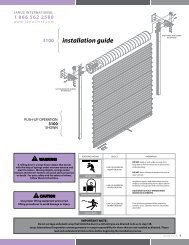
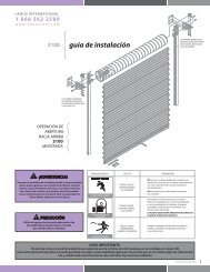
<strong>SERIES</strong> <strong>650</strong><br />
<strong>installation</strong> <strong>guide</strong><br />
IMPORTANT NOTE:<br />
Do not cut tape and plastic wrap that holds the door<br />
in a roll until you are directed to do so in step 6B.<br />
<strong>Janus</strong> <strong>International</strong> Corporation cannot guarantee<br />
or accept responsibility for doors that are not<br />
installed as directed. Please read and understand all<br />
instructions before beginning the <strong>installation</strong><br />
process.<br />
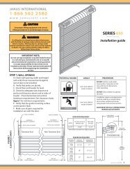
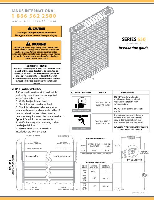
STEP 1: WALL OPENING<br />
A. Check wall opening width and height<br />
and verify these measurements against<br />
size of door to be installed.<br />
B. Verify that jambs are plumb.<br />
C. Check floor and header for level.<br />
D. Check for adequate side clearance at<br />
jambs and clearance above and at sides of<br />
header. Check horizontal and vertical<br />
headroom requirements. See clearance charts<br />
figure 1 for minimum requirements.<br />
E. Verify that the <strong>guide</strong> mounting surface<br />
on the jamb is flush.<br />
F. Make sure all parts required for<br />
<strong>installation</strong> are with the door.<br />
POTENTIAL HAZARD<br />
EXTREME SPRING TENSION<br />
MOVING DOOR<br />
EFFECT<br />
CAN CAUSE SERIOUS<br />
INJURY OR DEATH<br />
CAN CAUSE SERIOUS<br />
INJURY OR DEATH<br />
PREVENTION<br />
DO NOT stand or walk under<br />
moving door. Keep door in full<br />
view and free of obstructions<br />
while operating.<br />
DO NOT allow children to operate<br />
the door.<br />
Installation, repairs and adjustments<br />
must be made by a trained rolling<br />
service door systems technician<br />
using proper tools and instructions.<br />
DOOR MUST BE FULLY OPENED WHEN<br />
MAKING ADJUSTMENTS<br />
EDGE OF OPENING<br />
EDGE OF OPENING<br />
SIDE ROOM REQUIRED*<br />
HORIZONTAL<br />
HEADROOM<br />
FIGURE 1<br />
CLEARANCE CHARTS<br />
OUTSIDE OF<br />
BRACKET CLEARANCE<br />
END OF AXLE CLEARANCE<br />
Tensioner End<br />
OUTSIDE OF<br />
BRACKET CLEARANCE<br />
END OF AXLE CLEARANCE<br />
Non-Tensioner End<br />
GUIDE<br />
OUTSIDE OF EACH<br />
BRACKET LEG<br />
EACH END<br />
OF AXLE<br />
2-1/4” 3-3/8” 3-1/4”<br />
*Dimensions are taken from edge of opening<br />
OPENING<br />
HEIGHT<br />
THRU<br />
7’-4”<br />
OVER<br />
7’-4”<br />
THRU<br />
8’-8”<br />
HEADROOM REQUIRED<br />
VERTICAL<br />
HEADROOM<br />
15-1/2”<br />
16”<br />
HORIZONTAL<br />
HEADROOM<br />
17”<br />
17-1/2”<br />
TENSIONER END<br />
VERTICAL<br />
HEADROOM<br />
WALL<br />
OPENING<br />
HEIGHT<br />
BACK OF<br />
GUIDE CLEARANCE<br />
BACK OF<br />
GUIDE CLEARANCE<br />
OVER<br />
8’-8”<br />
THRU<br />
10’ -0”<br />
17”<br />
18-1/4”<br />
revised 7/28/09 1
STEP 2: POSITION DOOR AND PARTS<br />
A. Make sure floor is clean in order to prevent damage to curtain.<br />
B. On inside of building, place left <strong>guide</strong> on floor perpendicular to opening with <strong>guide</strong> bottom close to the<br />
left jamb and the top toward inside of building. Do the same with the right <strong>guide</strong> to the right jamb. See<br />
figure 2.<br />
C. Place door on floor at top of and between <strong>guide</strong>s. Rotate door as necessary to locate bottom bar against<br />
floor. See figures 2 and 3.<br />
D. Distribute hardware parts to appropriate areas.<br />
TENSIONER BRACKET<br />
NOTCH<br />
GUIDE<br />
RIGHT<br />
GUIDE<br />
DOOR<br />
LEFT<br />
GUIDE<br />
LOCKING<br />
TAB<br />
FLANGE ON<br />
TENSIONER<br />
PAWL<br />
OPENING<br />
BEGINNING BOTTOM<br />
BAR POSITION<br />
FLOOR<br />
TENSIONER<br />
RATCHET<br />
WHEEL<br />
FIGURE 2<br />
DOOR POSITION ON FLOOR<br />
FIGURE 3<br />
GUIDE TO BRACKET INSTALLATION<br />
NOTE: Brackets, tensioner, spring(s) and curtain mounted latch are pre-assembled to the<br />
door at the factory. Do not remove.<br />
STEP 3: GUIDES TO BRACKETS INSTALLATION<br />
A. At tensioner end of door, lift flange on tensioner pawl until end of the pawl clears the tensioner ratchet<br />
wheel. Rotate bracket in order to position short leg end upward. Release flange on pawl and allow end<br />
to engage with the nearest tooth on the ratchet wheel. See figure 3.<br />
B. Bring top end of <strong>guide</strong> in alignment with bracket and insert hooks on bracket into slots in <strong>guide</strong>.<br />
C. Slide bracket and <strong>guide</strong> together until locking tab in <strong>guide</strong> fully engages notch in bracket.<br />
D. If locking tab does not fully engage with bracket notch, use a hammer and punch to bend tab into<br />
bracket notch.<br />
E. Repeat steps 3B through 3D for non-tension bracket and <strong>guide</strong>. The bracket will require being held in<br />
position.<br />
WARNING!<br />
Locking tab in <strong>guide</strong> must fully engage with notch in bracket. Failure to do so may allow the door to<br />
fall during <strong>installation</strong>, which can cause serious injury or death and/or damage to door.<br />
NOTE: For opening heights over 8'-8", clamp bottom of brackets to <strong>guide</strong>s with locking pliers in order<br />
to ensure rigidity of top of <strong>guide</strong> while lifting. Remove pliers after securing brackets to jambs.<br />
2"<br />
2"<br />
2"<br />
3 -1/2"Min.<br />
2"<br />
2"<br />
2"<br />
FIGURE 4<br />
UNIVERSAL<br />
MOUNT<br />
GUIDES<br />
1-1/2"<br />
FIGURE 5<br />
LIP<br />
DETAIL<br />
2<br />
WOOD JAMBS<br />
USING 1/4-10 X 1" LAG<br />
revised 7/28/09<br />
CONCRETE/MASONRY JAMBS<br />
USING 1/4" X 1-3/4" WEDGE-BOLT<br />
STEEL JAMBS<br />
USING 1/4-14 X 1" TEKS<br />
RAIN LIP DETAIL
STEP 4: LIFTING DOOR ASSEMBLY<br />
A. Move door and <strong>guide</strong> assemblies toward wall opening with bottom<br />
of <strong>guide</strong>s resting next to jambs.<br />
B. Lift door assembly evenly, pivoting around bottom of <strong>guide</strong>s. See figure 6.<br />
WARNING!<br />
Two installers are required to lift door assembly into position<br />
against jambs. The <strong>guide</strong>s are not designed to support the door<br />
weight during a one man <strong>installation</strong>. Attempting <strong>installation</strong> with<br />
only one installer can result in serious injury and/or damage to door.<br />
Do not leave door unattended until it is securely attached to jambs.<br />
O<br />
P<br />
E<br />
N<br />
I<br />
N<br />
G<br />
FLOOR<br />
FIGURE 6<br />
STEP 5: GUIDES AND BRACKETS TO JAMB<br />
LIFTING DOOR ASSEMBLY<br />
A. Attach brackets and <strong>guide</strong>s to jambs using fasteners shown in table 1.<br />
B. The <strong>guide</strong>s should be mounted centered about the opening and spaced curtain width + 1" apart measured<br />
from back of <strong>guide</strong> to back of <strong>guide</strong>. See figure 7. Both <strong>guide</strong>s must be plumb.<br />
C. The appropriate fastener must be installed at each hole location in brackets and <strong>guide</strong>s. See table 1.<br />
TABLE 1: Wall Fasteners included for jamb attachment of Brackets and Guides.<br />
ITEM JAMB FASTENERS<br />
Brackets Concrete or Filled Block 1/4" x 1-3/4” Powers Wedge-Bolt<br />
Steel-Structural<br />
1/4”-14 x 1” TEKS Screw<br />
and<br />
Steel-Rollup Frame 1/4”-14 x 7/8” Stitch TEKS Screw<br />
Guides<br />
Wood<br />
1/4”-10 x 1” Lag Screw<br />
DRILL SIZE<br />
Powers 01314<br />
None<br />
None<br />
None<br />
EDGE OF OPENING<br />
2"<br />
WARNING!<br />
Door can fall if both brackets are not securely fastened to the jambs.<br />
All fasteners attaching brackets to jambs must fit securely into a<br />
structural member or surface. If door falls, serious injury or death<br />
and/or damage to door can result.<br />
2"<br />
CURTAIN WIDTH + 1"<br />
FASTENER LOCATION<br />
FOR ALL JAMBS<br />
NOTE:<br />
Welding of <strong>guide</strong>s to the jambs is not recommended.<br />
FIGURE 7<br />
DOOR CROSS SECTION<br />
STEP 6: SETTING INITIAL SPRING TENSION<br />
A. Rotate door 1-1/2 revolutions in the direction that would send the bottom bar down through the <strong>guide</strong>s.<br />
B. While firmly holding the door at the bottom bar, cut the tape and plastic wrap that holds the door in a<br />
coil. Direct the bottom bar down into the <strong>guide</strong>s, stopping just past the head stop area and hold securely<br />
through completion of step 7.<br />
WARNING!<br />
Extreme spring tension can cause serious injury or death. Installation, repairs and adjustments must be made by a<br />
trained rolling service door systems technician using proper tools and instructions.<br />
Door must be fully opened when making adjustments.<br />
revised 7/28/09 3
STEP 7: HEAD STOPS<br />
A. Slide head stop from inside of each <strong>guide</strong>. See figure 8.<br />
B. Secure each head stop to <strong>guide</strong> with 1/4-20 x 1/2” thread cutting type F hex screw.<br />
DOOR CURTAIN<br />
FIGURE 8<br />
HEAD STOP<br />
FIGURE 9<br />
OPTIONAL<br />
BOTTOM BAR<br />
MOUNTED<br />
SLIDE LOCKS<br />
HEX BOLT<br />
1/4 20 X 1”<br />
BOTTOM BAR<br />
ANGLE<br />
ASTRAGAL<br />
HEX NUT 5/16 - 18<br />
SLIDE LOCK<br />
STEP PLATE<br />
NYLON INSERT NUT<br />
1/4 - 20<br />
FLAT WASHER 1/4”<br />
STEP 8:<br />
DOOR STOP CLIPS, HANDLE(S) AND PULL ROPE<br />
A. Install stop clip at each end on inside of bottom<br />
bar using existing single 1/4-20 x 5/8"<br />
carriage bolt and nut. See figure 10.<br />
B. Install handle(s) on outside of bottom<br />
bar using 1/4-20 x 5/8“ carriage bolts<br />
and nuts.<br />
C. Install rope in one of the holes at the<br />
center of the horizontal leg of the<br />
bottom bar angle.<br />
OPTIONAL: BOTTOM BAR MOUNTED SLIDE LOCKS.<br />
See figure 9 for <strong>installation</strong>.<br />
FIGURE 10<br />
DOOR STOP<br />
CLIP<br />
DOOR CURTAIN<br />
HEX BOLT<br />
1/4 20 X 1”<br />
HANDLE<br />
BOTTOM BAR<br />
ANGLE<br />
ASTRAGAL<br />
DOOR STOP CLIP<br />
NYLON INSERT NUT<br />
1/4 20<br />
STEP 9: CHECK DOOR OPERATION<br />
A. Lower and raise the door to test the door balance.<br />
B. If door is easy to close, but hard to open; increase spring tension.<br />
C. If door is hard to close, but easy to open; decrease spring tension.<br />
STEP 10: ADJUST SPRING TENSION<br />
A. Place 3/8" diameter winding bar in tensioner ratchet wheel. See figure 11.<br />
B. Rotate winding bar in the down direction to increase spring tension. Each engagement of a tooth equals 1/8 turn.<br />
C. To decrease spring tension, pull down slightly on winding bar until pawl disengages tooth. Lift flange on<br />
pawl and move winding bar up until past the pawl/tooth engagement. Allow pawl to rest on ratchet wheel<br />
and continue moving winding bar up until the pawl is fully engaged with the tooth.<br />
D. Remove winding bar and operate door.<br />
LESS<br />
E. Repeat steps 10A through 10D as necessary.<br />
TENSION<br />
FLANGE ON<br />
TENSIONER<br />
PAWL<br />
WARNING!<br />
DOOR MUST BE FULLY OPENED<br />
WHEN MAKING ADJUSTMENTS.<br />
TENSIONER<br />
BRACKET<br />
WARNING!<br />
Installation of door stop clips are required. Failure to properly install clips can cause the door curtain<br />
to travel beyond the <strong>guide</strong>s resulting in door damage and or personal injury.<br />
TENSIONER<br />
RATCHET WHEEL<br />
MORE<br />
TENSION<br />
WINDING BAR<br />
3/8" DIAMETER<br />
FIGURE 11<br />
ADJUST<br />
SPRING<br />
TENSION<br />
4<br />
revised 7/28/09<br />
NOTE: Latch slide slot in the <strong>guide</strong> may require adjusting after door <strong>installation</strong><br />
due to variances in manufacturing and/or site conditions.