Glidermatic⢠- Janus International
Glidermatic⢠- Janus International
Glidermatic⢠- Janus International

Create successful ePaper yourself
Turn your PDF publications into a flip-book with our unique Google optimized e-Paper software.
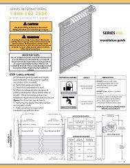
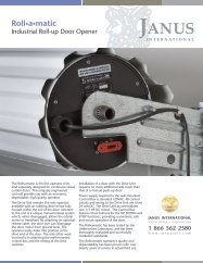
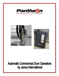
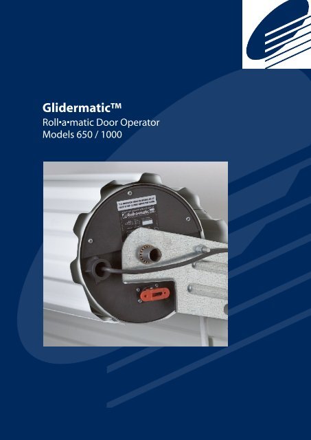
Glidermatic<br />
Roll•a•matic Door Operator<br />
Models 650 / 1000
Glidermatic<br />
Roll•a•matic Door Operator<br />
Models 650 / 1000<br />
Important Safety Instructions<br />
• DO NOT operate unless the door is completely visible and clear of obstructions including children,<br />
persons, vehicles or other objects. SEVERE PERSONAL INJURY, property damage or even DEATH<br />
may result if this warning is not followed<br />
• DO NOT operate the door if children or persons are near the opening. Children must always be<br />
supervised when near the door at all times the operator is in use<br />
• DO NOT allow children to operate the door. SEVERE PERSONAL INJURY, property damage or even<br />
DEATH may result if this warning is not followed.<br />
• The SAFETY REVERSING function should be tested on a monthly basis to ensure it is set correctly and<br />
the door will reverse on its downward motion when an obstruction is encountered. If this function does<br />
not operate DISCONTINUE USE and contact a qualified service technician.<br />
• If additional SAFETY is required, it is STRONGLY recommended that a Photo Electric Cell or Sensing<br />
Edge device be installed. It is mandatory that such devices be used in conjunction with radio control<br />
units or when momentary contact on close function is enabled.<br />
• When the Automatic Close function or Radio Transmitters are being used, a Sensing Edge or Photo<br />
Electric Cell must be correctly fitted and tested on a regular basis. If SAFETY features do not operate<br />
correctly, DISCONTINUE USE and contact a qualified service technician.<br />
• When possible activate the manual release only when the door is closed. Weak or broken springs may<br />
allow the door to fall rapidly, causing SEVERE INJURY or even DEATH. In all cases stand clear of the<br />
door. In the event that the door appears to fall, a qualified service technician will be required to adjust<br />
the spring tension.<br />
• Install the control unit on the same side of the door as the drive unit with an uninterrupted view of the<br />
door and opening. The control unit should be installed in a suitable location to ensure it is protected<br />
from the elements. Under NO CIRCUMSTANCES should the unit be exposed to water.<br />
• When installing the operator on an existing door, ensure it is good operating order. Ensure the<br />
springs are not weak or broken and the door is free of sticking or binding. Contact a qualified service<br />
technician for attention to any of these issues.<br />
• If any wiring is damaged, it MUST BE replaced by a qualified service technician in accordance with<br />
the NATIONAL ELECTRIC CODE and the manufacturer’s detail.<br />
• Ensure the door is completely open before proceeding through the doorway.<br />
User Manual 1
Glidermatic<br />
Roll•a•matic Door Operator<br />
Models 650 / 1000<br />
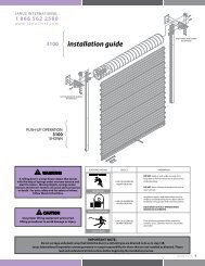
Drive Unit<br />
Exploded Parts Diagram<br />
1. Low voltage DC motor<br />
2. Main drive gear<br />
3. Drum wheel<br />
4. Open and close limit switches<br />
5. Cam Gears<br />
6. Manual release lever<br />
7. Drive unit plate<br />
8. Adaptor<br />
9. Slip ring bushing<br />
10. Ring Gear<br />
11. Cam cover<br />
2<br />
1<br />
3<br />
8<br />
11<br />
5<br />
9<br />
7<br />
4 10<br />
6<br />
This manual refers to settings and connections to be performed on the DRIVE UNIT and CONTROL<br />
UNIT, not the installation of the door<br />
User Manual 2
Glidermatic<br />
Roll•a•matic Door Operator<br />
Models 650 / 1000<br />
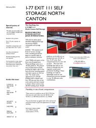
Control Unit<br />
The CONTROL UNIT is best mounted on the same side as the drive unit with an uninterrupted view of<br />
the door.<br />
It is essential that the CONTROL UNIT be securely attached to the wall or structure involved through the<br />
four mounting holes provided.<br />
Connect the CONTROL UNIT to a 115-volt single phase AC 2.0 AMP power source, being sure to follow<br />
local wiring codes, or National Electric Code where applicable<br />
Suitable rigid conduit should be used to protect all wiring, and be securely fixed<br />
Ensure the unit is properly grounded using the grounding post (green lead) in the splice connection area.<br />
Splice connection area<br />
Access for<br />
main power<br />
115VAC<br />
Connect drive unit wiring to<br />
terminal J6,<br />
Access wiring through strain<br />
relief bushing.<br />
Mounting<br />
Holes<br />
J6<br />
Circuit breaker<br />
Strain Relief Bushing<br />
During normal operating<br />
conditions a current draw of<br />
2 amps is expected.<br />
Caution:<br />
Attach the WARNING LABEL adjacent to<br />
the control unit<br />
User Manual 3
Glidermatic<br />
Roll•a•matic Door Operator<br />
Models 650 / 1000<br />
Handing of the Operator (Check Setting)<br />
All 650 Series Operators as standard factory issue, are configured to Right Hand operation when<br />
viewed from the inside looking outward. Ensure jumper setting is correct prior to operation<br />
Caution:<br />
Always disconnect power to unit BEFORE making these setting changes.<br />
1. The 650 Series Operator is for Right Hand<br />
operation only - when viewed from inside<br />
looking outwards<br />
2. Ensure Jumper JP6 is set for Right Hand<br />
operation (RH) according to the diagram<br />
L/H<br />
JP6<br />
DRIVE<br />
R/H<br />
User Manual 4
Glidermatic<br />
Roll•a•matic Door Operator<br />
Models 650 / 1000<br />
Manual Operation<br />
In the event of power failure or situations where manual operation of the door is required.<br />
Manual operation is activated by use of the Manual Release Lever. Activating the Manual<br />
Release Lever will automatically disconnect electrical power to the motor. The motor will not<br />
operate unless the lever is fully engaged in the electric operation position.<br />
Manual<br />
Release Lever<br />
Electric Operation<br />
Manual Operation<br />
When normal electric operation is required, return the lever to the Electric Operation<br />
position. Engage the spring loaded release pin by carefully moving the door in either direction<br />
until pin engagement is noted and the unit is locked in position<br />
WARNING:<br />
When possible activate the manual release only when the door is closed. Weak<br />
or broken springs may allow the door to fall rapidly, causing severe injury or even<br />
death. In all cases stand clear of the door. In the event that the door appears to fall<br />
a qualified service technician will be required to adjust the spring tension<br />
User Manual 5
Glidermatic<br />
Roll•a•matic Door Operator<br />
Models 650 / 1000<br />
Door Travel Adjustment<br />
The door travel limit is determined by rotation of cams in the drive unit. The cams are driven by a gear<br />
mechanism and activate a limit switch at the desired position.<br />
• The inner cam determines the closed position.<br />
• The outer cam determines the open position.<br />
Caution:<br />
To adjust<br />
• Set door to manual operation using the manual release lever<br />
(Refer to Manual Operation on page 5)<br />
• Remove the cam cover on the drive unit to gain access to the<br />
internal cams<br />
• Loosen cam gear screws (x3)<br />
Closing - inner cam<br />
• To set the closing position, manually lower the door to the<br />
required closed position observing the direction of rotation of the<br />
inner most cam<br />
• Rotate the inner cam in the direction observed until it activates<br />
the inner limit switch<br />
Opening - outer cam<br />
• To set the opening height, manually raise the door to the<br />
desired open position (ensure the bottom bar is short of<br />
contacting the head stop), observing the direction of rotation of<br />
the outer cam<br />
• Rotate the outer cam in the direction observed until it activates<br />
the outer limit switch<br />
To complete<br />
• Tighten the cam gear screws (x3)<br />
• Return manual release lever to electric operation position<br />
• Carefully move the door in either direction until pin engagement<br />
is noted and the unit is locked into position (Refer to Manual<br />
Operation on page 5)<br />
• Reinstall the cam cover after operating door electrically and<br />
verifying limits of door travel.<br />
Care should be taken to ensure the lever arms on the limit switch are not obstructed by the rotation of<br />
the gearing.<br />
The motorized travel of the door is directly controlled by the Cam adjustment<br />
settings. Please ensure the required door travel is correctly set.<br />
User Manual 6
Glidermatic<br />
Roll•a•matic Door Operator<br />
Models 650 / 1000<br />
Push Button Operation<br />
All control units as standard issue are configured to operate with push button operation featuring momentary<br />
contact to open and constant contact to close, as such:<br />
Momentary Contact to Open<br />
UP<br />
A single press will operate the door in the upward direction.<br />
Constant Contact to Close<br />
DOWN<br />
Continuous pressure needs to be applied to the down button to<br />
drive the door downward (Hold to run). Releasing this button will stop the door.<br />
STOP/RESET<br />
Pressing this button will STOP the door<br />
Caution:<br />
Always disconnect power to unit BEFORE making any setting changes.<br />
Momentary Contact to Close<br />
It is possible to convert the push button operation to Momentary<br />
Contact to Close from Constant Contact to Close.<br />
This will enable a single press of the down button to close the door.<br />
To enable this, move jumper on JP4 Latch terminal from OFF to<br />
ON<br />
When enabling momentary contact closing operation it is essential that a supplementary safety device such<br />
as a Sensing Edge or Photo Electric Cell be fitted to prevent injury or entrapment. Once enabled for<br />
momentary contact on close - the unit will not operate unless a supplementary safety device is fitted and the<br />
jumpers at JP3 and JP5 set accordingly. Refer to pages 9 and 10.<br />
User Manual 7
Glidermatic<br />
Roll•a•matic Door Operator<br />
Models 650 / 1000<br />
Safety Reversing<br />
An inherent safety feature of the Glidermatic operator is the overload function. This ensures that a closing<br />
door will stop and reverse its motion if an obstruction is encountered<br />
Caution:<br />
Always disconnect power to unit BEFORE making any setting changes.<br />
Torque Setting<br />
The Glidermatic operator is designed to stop and reverse its<br />
downward operation if it encounters an obstruction. This is set by<br />
adjusting JP1 to the lowest current that will allow the door to close<br />
during normal operation.<br />
Start by testing with the jumper JP1 set at 4. If the door will not<br />
close, proceed testing with JP1 set at 3. Continue setting JP1<br />
until the door will completely close.<br />
The current settings are:<br />
1. 5.5 amps (largest door)<br />
2. 4.5 amps<br />
3. 3.5 amps<br />
4. 2.5 amps (smallest door)<br />
The overload function should be tested on a regular monthly basis to ensure the door will reverse on<br />
its downward motion when an obstruction is encountered. If this function does not operate discontinue<br />
use and contact a qualified service technician.<br />
User Manual 8
Glidermatic<br />
Roll•a•matic Door Operator<br />
Models 650 / 1000<br />
Photo Electric Cell Wiring<br />
Consult the installation instructions supplied by manufacturer of the Photo Electric Cell and determine<br />
whether the contacts are normally open (N/O) or normally closed (N/C).<br />
Caution:<br />
Always disconnect power to unit BEFORE making any setting changes.<br />
Connect the two wires from the<br />
Photo Electric Cell receiver<br />
output terminals to the terminals<br />
marked PCELL on wiring<br />
terminal J5.<br />
N/C<br />
N/O<br />
OFF<br />
MOVE<br />
N/C<br />
N/O<br />
OFF<br />
If the Photo Electric Cell<br />
output uses normally open<br />
contacts, move jumper on JP5<br />
from OFF to N/O.<br />
TO<br />
If the Photo Electric Cell<br />
output terminals feature<br />
normally closed contacts,<br />
move jumper on JP5 from OFF<br />
to N/C.<br />
N/C<br />
N/O<br />
OFF<br />
TO<br />
Photo Electric Cells are recommended as a supplementary safety system. If required, 12 or 24 VDC<br />
power may be sourced from terminals 5 & 6 of J3. Ensure jumper JP2 is configured to match required<br />
voltage of photo electric cell. Refer to page 11.<br />
User Manual 9
Glidermatic<br />
Roll•a•matic Door Operator<br />
Models 650 / 1000<br />
Sensing Edge Wiring<br />
Consult the installation instructions supplied by manufacturer of the Sensing Edge device and determine<br />
whether the contacts are normally open (N/O) or normally closed (N/C) .<br />
Caution:<br />
Always disconnect power to unit BEFORE making any setting changes.<br />
Connect the two wires from<br />
the Sensing Edge terminals<br />
marked EDGE on terminal block<br />
J5.<br />
N/C<br />
N/O<br />
OFF<br />
MOVE<br />
N/C<br />
N/O<br />
OFF<br />
If the Sensing Edge contacts<br />
are normally open, move<br />
jumper on JP3 from OFF to<br />
N/O.<br />
TO<br />
If the Sensing Edge features<br />
normally closed contacts,<br />
move jumper on JP3 from OFF<br />
to N/C.<br />
N/C<br />
N/O<br />
OFF<br />
TO<br />
Sensing Edge devices are recommended as a supplementary safety system. If required, 12 or 24<br />
VDC power may be sourced from terminals 5 & 6 of J3. Ensure jumper JP2 is configured to match<br />
required voltage of sensing edge. Refer to page 11.<br />
User Manual 10
Glidermatic<br />
Roll•a•matic Door Operator<br />
Models 650 / 1000<br />
Radio Control Wiring<br />
In order to operate the door with a wireless remote, an independent Radio Control Unit may be installed<br />
and connected to the Glidermatic control unit.<br />
Caution:<br />
Always disconnect power to unit BEFORE making any setting changes.<br />
Power to the receiver is supplied from terminals<br />
5 & 6 of J3<br />
5 is +v, 6 is ground<br />
Ensure Jumper JP2 is configured to match<br />
required voltage of radio control receiver.<br />
(5, 12 or 24VDC)<br />
Ground<br />
+V<br />
Single (Up/Down)<br />
STOP<br />
DOWN<br />
UP<br />
Single (Up/Down) Output Type<br />
Receiver<br />
Connect output of receiver to terminal 4 of J3<br />
Open/Close/Stop Type Receiver<br />
Connect terminals Up, Down and<br />
Stop of Radio Control Receiver to<br />
1, 2 & 3 respectively<br />
Ensure the jumper JP4 Latch terminal is set to ON<br />
Edge jumper JP3 is set to N/O or N/C<br />
Pcell jumper JP5 is set to N/O or N/C<br />
In accordance with the instructions supplied by the<br />
manufacturer of the supplementary safety system<br />
It is essential that a supplementary safety device such as a Sensing Edge or Photo Electric Cell<br />
be fitted when radio control unit is installed to prevent injury or entrapment<br />
Once any radio receiver unit is connected the unit will not operate unless a supplementary safety<br />
device is fitted and the jumpers at JP3 and JP5 set accordingly. Refer to pages 9 and 10.<br />
User Manual 11
Glidermatic<br />
Roll•a•matic Door Operator<br />
Models 650 / 1000<br />
Radio Control Wiring<br />
There are several popular Radio control receivers that may be connected to the Glidermatic control<br />
unit. The wiring configuration for some of these units is highlighted below.<br />
Receiver<br />
Circuit Board<br />
3<br />
2<br />
1<br />
4<br />
5<br />
6<br />
3<br />
2<br />
1<br />
4<br />
5<br />
6<br />
3<br />
2<br />
1<br />
4<br />
5<br />
6<br />
3<br />
2<br />
1<br />
4<br />
5<br />
6<br />
Consult the installation instructions supplied by the manufacturer of the radio control unit being installed<br />
for further detail including the coding of hand transmitters<br />
User Manual 12
Glidermatic<br />
Roll•a•matic Door Operator<br />
Models 650 / 1000<br />
Automatic Close Function<br />
The Glidermatic operator can be configured to automatically close the door after a prescribed period of<br />
time up to 12 minutes<br />
Caution:<br />
Always disconnect power to unit BEFORE making any setting changes.<br />
Enable Automatic Close (JP4)<br />
To enable the Automatic Close Function, move Jumper on JP4<br />
A/C terminal from OFF to ON<br />
Adjust timer<br />
Timer can be adjusted using the potentiometer A/CLOSE to<br />
achieve a maximum time delay of 12 minutes<br />
Once enabled for automatic close - the unit will not operate unless a supplementary saftey device is<br />
fitted and the jumpers at JP3 and or JP5 set accordingly. Refer to pages 9 and 10.<br />
User Manual 13