Appendix D - Data Sheets Of Key Components
Appendix D - Data Sheets Of Key Components
Appendix D - Data Sheets Of Key Components

You also want an ePaper? Increase the reach of your titles
YUMPU automatically turns print PDFs into web optimized ePapers that Google loves.
<strong>Appendix</strong> D - <strong>Data</strong> <strong>Sheets</strong> <strong>Of</strong> <strong>Key</strong> <strong>Components</strong><br />
• E2580 EML Agere<br />
Application Notes<br />
• LTC1923 TEC controller Linear Technology<br />
Application Notes<br />
• HY6330 Laser Diode Driver Hytek<br />
• MAX525 Digital to Analog Converter Maxim<br />
• ADS7841 Analog to Digital Converter Burr Brown Products (TI)<br />
• MAX 487 RS422 Transceiver Maxim
Application Note<br />
May 2000<br />
E2580 EML with Intergral Driver IC: Pin Definitions and Operation<br />
Introduction<br />
Agere Systems Inc.'s E2580 series Electroabsorption Modulated Isolated Laser Module (EM-ILM or EML)<br />
offers an integrated modulator and CW laser in a single semiconductor chip, and an integral driver IC in the<br />
same package.<br />
This application note is intended to offer guidance on the pin functions and the voltage levels required by the<br />
driver IC. For general guidance in setup and operation of EML devices, refer to the Electroabsorptive Modulated<br />
Laser (EML): Setup and Optimization Technical Note (TN00-008OPTO). For additional information on the wavelength<br />
stability of 2.5 Gbits/s and 10 Gbits/s EML devices over temperature, refer to the technical note, Use of<br />
EML Devices In DWDM Applications (TN00-012OPTO).<br />
Pin Definitions and Operation<br />
As indicated in the block diagram below, the E2580 device has 13 pins on one side of the package that are dedicated<br />
to the required dc and control components, and a single, small-profile, Glibert GPO connector on the<br />
other side for the RF signal. Pins 6 to 11 interface to the integral driver IC, which in turn controls the modulator<br />
functions. Pins 1 and 2 connect the thermistor, pin 3 connects the CW laser section, pins 4 and 5 connect the<br />
monitor photodiode, and pins 12 and 13 connect the thermoelectric cooler.<br />
13. TEC–<br />
TEC<br />
12. TEC+<br />
RF INPUT<br />
DRIVER<br />
IN<br />
GND<br />
OUT<br />
11. VSS<br />
10. DCA<br />
9. OA<br />
8. NC<br />
7. NC<br />
6. VEA<br />
5. BACK DET+<br />
4. BACK DET–<br />
3. LASER+<br />
2. THERM<br />
1. THERM<br />
LASER–, CASE<br />
1-1098(F)<br />
Figure 1. Block Diagram of the E2580 10 Gbits/s EML Package with<br />
Driver IC and Output Amplitude/Cross Point Control Circuits
E2580 EML with Integral Driver IC:<br />
Pin Definitions and Operation<br />
Application Note<br />
May 2000<br />
Pin Definitions and Operation (continued)<br />
Table 1. Pin Definitions and Operation<br />
PIn<br />
Number<br />
Symbol<br />
Description<br />
13 TEC(–) Thermoelectric Cooler (–).<br />
12 TEC(+) Thermoelectric Cooler (+).<br />
11 VSS Voltage Supply to the IC. The operating voltage range is –5.0 V to –5.5 V.<br />
10 DCA Duty Cycle Adjust. The input range is ~ –3.6 V to –3.8 V. At ~ –3.6 V, the<br />
pulse width is reduced to a minimum value of 70%. At ~ –3.8 V, the pulse<br />
width is a maximum at 130%. Typically, around –3.7 V, the pulse width is<br />
100%, which corresponds to a normal duty cycle and 50% eye crossing for<br />
the electrical drive pattern. This will produce lower eye crossings in the optical<br />
pattern for an EML device because of the nonlinear extinction (light output<br />
vs. modulation voltage) characteristic. This input can be used to increase<br />
the crossings slightly for optimal performance.<br />
9 OA Output Amplitude Adjust. The input range is ~ –4.2 V to –4.8 V. Minimum<br />
drive amplitude to the modulator (~ 2 Vp-p) is achieved at –4.8 V. Maximum<br />
drive (~ 3 Vp-p) is attained at –4.2 V. This input can be used to adjust the<br />
extinction ratio in the optical output.<br />
8 NC/DCM No Connect/Duty Cycle Monitor. This pin is reserved for the duty cycle<br />
monitor function and may be available in future transponder versions. Currently,<br />
this functionality is not available on the driver ICs that are used in<br />
E2560. It will be NC, (no connect) on initial models.<br />
7 NC/PCM No Connect/Peak Current Monitor. This pin is reserved for the peak current<br />
monitor function. As with the duty cycle monitor, it is not yet available on<br />
the driver ICs used. It will be NC (no connect) on initial models<br />
6 VEA Modulator <strong>Of</strong>fset. This pin controls the on-state bias voltage applied to the<br />
modulator. The input voltage ranges from –3.0 V to –5.0 V. At –5.0 V, there is<br />
no applied offset to the modulator, i.e., the on-state should be close to 0.0 V<br />
(excluding the effects of modulator photocurrent). At –3.0 V, the maximum<br />
offset is applied to the modulator, which would correspond to an on-state<br />
voltage of –1.0 V. The absolute minimum off-state is –3.4 V for the driver IC.<br />
Therefore, tuning the offset to more negative value at a fixed output amplitude<br />
will eventually result in clipping on the low end and a reduction in the<br />
drive amplitude. For example, if a package is set up for 2.5 Vp-p output<br />
amplitude, it may be tuned down for offset to –0.9 V maximum before amplitude<br />
clipping would normally occur. At –1.0 V offset, the maximum driver<br />
amplitude would be reduced to 2.4 Vp-p.<br />
5 Back Det(+) Back Detector (+) (Cathode).<br />
4 Back Det(–) Back Detector (–) (Anode).<br />
3 Laser(+) Laser (+) (Anode).<br />
2 Therm Thermistor Connect.<br />
1 Therm/Laser(–)/Case Thermistor/Laser (–)/Case.This pin offers a combined thermistor, laser CW<br />
section cathode (–) and case ground (for the RF signal). This is a modification<br />
on earlier models and has been introduced to offer optimum RF performance.<br />
— RFIN RF Input. The RF signal is applied to the Gilbert GPO connector. Via this<br />
connection, the driver IC requires an input voltage in the range 0.5 V to 1.0 V<br />
(peak to peak) for optimum performance. The RF path is optimized for a<br />
nominal input impedance of 50 Ω.<br />
2 Agere Systems Inc.
Application Note<br />
May 2000<br />
E2580 EML with Integral Driver IC:<br />
Pin Definitions and Operation<br />
Pin Definitions and Operation (continued)<br />
(CASE)<br />
REF<br />
IN<br />
OUT<br />
DCA<br />
VSS OA VEA<br />
Figure 2. Driver IC Block Diagram<br />
1-1011(F)<br />
IN<br />
(GPO)<br />
CROSS<br />
POINT<br />
CONTROL<br />
CIRCUIT<br />
7.5 kΩ<br />
3.8 kΩ 3.8 kΩ<br />
GND<br />
1ST STAGE<br />
SOURCE<br />
FOLLOWER<br />
1ST STAGE<br />
DIFFERENTIAL<br />
AMPLIFIER<br />
40 Ω 40 Ω<br />
10 kΩ<br />
VARIABLE<br />
RESISTOR<br />
REF<br />
DCA<br />
10 Ω 10 Ω 10 Ω 10 Ω<br />
1.3 kΩ<br />
VSS<br />
DRIVER IC<br />
1.2 kΩ 1.2 kΩ<br />
VSS<br />
SUPPLY<br />
VOLTAGE<br />
Figure 3. Cross Point Control Circuit Example<br />
1-1100(F)<br />
Agere Systems Inc. 3
E2580 EML with Integral Driver IC:<br />
Pin Definitions and Operation<br />
Application Note<br />
May 2000<br />
Pin Definitions and Operation (continued)<br />
OUTPUT<br />
AMPLITUDE<br />
CONTROL<br />
CIRCUIT<br />
GND<br />
DRIVER IC<br />
GND<br />
CURRENT SOURCE FET<br />
OF OUTPUT DIFFERENTIAL<br />
AMPLIFIER<br />
VARIABLE<br />
RESISTOR<br />
OA<br />
VSS<br />
SUPPLY<br />
VOLTAGE<br />
Figure 4. Output Amplitude Control Circuit Example (10 Gbits/s EA Driver IC)<br />
1-1099(F)<br />
Recommended Start-Point Conditions<br />
With the appropriate control circuits in place, as described above, the following starting point (i.e., prior to any tuning)<br />
values are suggested for the dc bias parameters in the IC.<br />
Table 2. Recommended Start-point Conditions for dc Bias Parameters in the IC*<br />
Parameter Symbol Value<br />
Duty Cycle Adjust DCA –3.7 ± 0.1 V<br />
Modulation <strong>Of</strong>fset VEA –3.5 ± 0.3 V<br />
Output Amplitude OA –4.6 ± 0.2 V<br />
* The information offered here is recommended as a time-saving condition and further adjustment may be necessary to achieve the desired performance,<br />
as described in Table 1.<br />
Summary<br />
In conjunction with the technical note describing general setup and optimization of the EML device, the user should<br />
now be in a position to design the interface to the E2580 package, and, subsequently, to optimize its performance<br />
to meet the individual system requirements.<br />
4 Agere Systems Inc.
Application Note<br />
May 2000<br />
E2580 EML with Integral Driver IC:<br />
Pin Definitions and Operation<br />
<strong>Appendix</strong><br />
RISE TIME = 37 ps, FALL TIME = 40 ps.<br />
1-1102(F)<br />
Figure 5. E2580xx Eye Pattern (Example)<br />
E–04<br />
E–05<br />
PENALTY @ 50 km = 0.3 dB<br />
PENALTY @ 88.5 km = 1.0 dB<br />
E–06<br />
E–07<br />
0 km<br />
50 km<br />
88.5 km<br />
E–08<br />
E–09<br />
E–10<br />
E–11<br />
–23 –22 –21 –20 –19 –18 –17 –16 –15<br />
RECEIVED POWER<br />
1-1097(F)<br />
Figure 6. E2581xx BER Performance (Example)<br />
Agere Systems Inc. 5
For additional information, contact your Agere Systems Account Manager or the following:<br />
INTERNET: http://www.agere.com<br />
E-MAIL: docmaster@agere.com<br />
N. AMERICA: Agere Systems Inc., 555 Union Boulevard, Room 30L-15P-BA, Allentown, PA 18109-3286<br />
1-800-372-2447, FAX 610-712-4106 (In CANADA: 1-800-553-2448, FAX 610-712-4106)<br />
ASIA: Agere Systems Hong Kong Ltd., Suites 3201 & 3210-12, 32/F, Tower 2, The Gateway, Harbour City, Kowloon<br />
Tel. (852) 3129-2000, FAX (852) 3129-2020<br />
CHINA: (86) 21-5047-1212 (Shanghai), (86) 10-6522-5566 (Beijing), (86) 755-695-7224 (Shenzhen)<br />
JAPAN: (81) 3-5421-1600 (Tokyo), KOREA: (82) 2-767-1850 (Seoul), SINGAPORE: (65) 778-8833, TAIWAN: (886) 2-2725-5858 (Taipei)<br />
EUROPE: Tel. (44) 7000 624624, FAX (44) 1344 488 045<br />
Agere Systems Inc. reserves the right to make changes to the product(s) or information contained herein without notice. No liability is assumed as a result of their use or application.<br />
Copyright © 2001 Agere Systems Inc.<br />
All Rights Reserved<br />
May 2000<br />
AP00-023OPTO
Technical Note<br />
August 2000<br />
Using Electroabsorbtive Modulated Laser Modules<br />
in Dense WDM Applications<br />
Introduction<br />
The information offered here is intended to serve as a guide in the use and optimization of Agere Systems Inc.’<br />
E2500 series of 2.5 Gbits/s and 10 Gbits/s Electroabsorptive Modulated Isolated Laser Module (EM-ILM, or<br />
EML) in dense wave-division multiplexing (DWDM) systems, where performance over temperature and, in particular,<br />
wavelength aging over life need to be characterized and understood. Use of the device without the introduction<br />
of a wavelength-locking element is discussed. Use of wavelength stabilized devices (e.g., Agere<br />
Systems’ C488/489-Type transmitters that employ an integrated wavelength locker) are not covered by this document.<br />
For general notes on the use of EML devices in long and ultralong haul transmission applications, refer to the<br />
Electroabsorption Modulated Laser (EML): Set-up and Optimization Technical Note, TN00-008OPTO.<br />
In DWDM systems, the use of laser devices tuned to specific wavelengths places specific constraints on the<br />
wavelength stability of those devices, both as a function of time and environmental conditions, particularly temperature.<br />
The available wavelength space between the chosen channels will be apportioned among the various<br />
components in the system by the system designer. In particular, the optical MUX and deMUX components, to<br />
the extent that they require their own wavelength drift budget over temperature and life, can leave only a small<br />
region in which the laser wavelength can drift or age before an overall system end-of-life condition is reached.<br />
Agere has extensively characterized wavelength stability over temperature and over life for a variety of source<br />
products. The EML device has been particularly well characterized and the results presented here are intended<br />
to assist the system designer in incorporating the EML into leading-edge DWDM designs.
Using Electroabsorbtive Modulated Laser Modules<br />
in Dense WDM Applications<br />
Technical Note<br />
August 2000<br />
Contributions to Wavelength Change<br />
(Drift) of EML Sources<br />
This document examines six critical aspects of device<br />
and system performance that need to be considered<br />
when establishing the budget for changes in wavelength<br />
for a component or system, including:<br />
■<br />
■<br />
■<br />
■<br />
■<br />
■<br />
Change in wavelength with case temperature variation<br />
(λ vs. TCASE)<br />
Change in wavelength with CW drive current to the<br />
DFB section (λ vs. IDFB)<br />
Change in wavelength owing to short-term changes<br />
in the EML chip temperature (λ vs. TCHIP)<br />
Aging of the thermistor<br />
Change in wavelength under environmental stress<br />
conditions<br />
Wavelength aging of the EML module<br />
Change in Wavelength with Case Temperature<br />
Variation (λ vs. TCASE)<br />
Although EML devices are temperature controlled by a<br />
thermoelectric cooler, all cooled optical sources are<br />
subject to some change in wavelength as the ambient<br />
or case temperature is varied. In particular, thermal<br />
crosstalk between the EML chip and the thermistor,<br />
and other aspects of the thermal design of the package,<br />
contribute to the overall stability performance. Figure<br />
1 shows the typical wavelength vs. case<br />
temperature performance of the EML, using twelve<br />
devices chosen at random.<br />
CHANGE IN WAVELENGTH<br />
(REF: 20 °C)/pm<br />
20<br />
15<br />
10<br />
5<br />
0<br />
–5<br />
–10<br />
–15<br />
0 10 20 30 40 50 60 70 80<br />
CASE TEMPERATURE (°C)<br />
Figure 1. EML Wavelength vs. Case Temperature (2.5 Gbits/s and 10 Gbits/s EML)<br />
1-1110(F)<br />
From these and other results, a worst-case change in case temperature of ±15 pm is guaranteed for the operating<br />
case temperature range 0 °C to 70 °C.<br />
2 Agere Systems Inc.
Technical Note<br />
August 2000<br />
Using Electroabsorbtive Modulated Laser Modules<br />
in Dense WDM Applications<br />
Change in Wavelength with CW Drive<br />
Current to the DFB Section (λ vs. IDFB)<br />
Due to the increased thermal load in the CW section as<br />
the drive current is increased, a small, corresponding<br />
increase in wavelength is observed. Figure 2 presents<br />
data showing typical wavelength vs. DFB current and<br />
indicates a worst-case value dλ/dIDFB of<br />
Using Electroabsorbtive Modulated Laser Modules<br />
in Dense WDM Applications<br />
Technical Note<br />
August 2000<br />
Change in Wavelength Owing to Short-<br />
Term Changes in EML Chip Temperature<br />
(λ vs. TCHIP)<br />
This is an additional contribution to the change in temperature<br />
of the EML chip, and depends on the integrity<br />
of the feedback loop that controls the thermoelectric<br />
cooler (TEC). Most TEC control loops are capable of<br />
controlling the chip temperature to one- or two-tenths<br />
of 1 °C. Once the system designer has identified any<br />
temperature variation owing to this cause, the data in<br />
Figure 3 may be used to identify the resulting change in<br />
wavelength.<br />
The two curves shown in Figure 3 represent modulator<br />
bias conditions of 0 V, and a typical nominal modulator<br />
bias condition of pkg-avg.<br />
The results indicate a median coefficient, dλ/dTCHIP, of<br />
0.85 A/°C, or 85 pm/°C, with a worst-case (+3 σ) value<br />
of 106 pm/°C.<br />
Note: The wavelength-aging predictions, discussed in<br />
the section on Wavelength Aging of the EML<br />
Module, page 7, include an assumed value of<br />
±0.25 °C for short-term changes in chip temperature.<br />
Therefore, there is no need to include any<br />
allowance for this reason where the results of the<br />
wavelength-aging simulation will be used, unless<br />
the predicted temperature change exceeds<br />
±0.25 °C.<br />
°<br />
TEMPERATURE COEFFICIENT OF WAVELENGTH (A/°C)<br />
1.00<br />
0.95<br />
0.90<br />
0.85<br />
0.80<br />
0.75<br />
0.70<br />
1% 2% 5% 10% 20% 30% 40% 50% 60% 70% 80% 90% 95% 98%<br />
0 V<br />
PKG-AVG<br />
N = 34, MEDIAN (PKG-AVG) = 0.85, SIGMA = 0.07<br />
N = 34, MEDIAN (0V) = 0.85, SIGMA = 0.06<br />
–2 –1 0 1 2<br />
Figure 3. Distribution of EML Wavelength vs. (Chip) Temperature<br />
1-1112(F)<br />
4 Agere Systems Inc.
Technical Note<br />
August 2000<br />
Using Electroabsorbtive Modulated Laser Modules<br />
in Dense WDM Applications<br />
Aging of the Thermistor<br />
Figure 4 presents data showing the measured aging of<br />
the thermistor resistance under stress conditions at<br />
125 °C for 1000 hours. A median resistance change of<br />
0.28% with a log normal dispersion of 1.0 is observed.<br />
For most applications, therefore, the results indicate<br />
that thermistor aging is negligible in terms of overall<br />
device performance.<br />
THERMISTOR AGING DATA<br />
–2 –1 0 1 2<br />
DELTA R @ 25 °C (%)<br />
10.00<br />
5.00<br />
1.00<br />
0.50<br />
0.10<br />
0.05<br />
MEDIAN = 0.1456, SDEV = 0.9982 100 HRS<br />
MEDIAN = 0.1892, SDEV = 0.9982 250 HRS<br />
MEDIAN = 0.2412, SDEV = 0.9982 500 HRS<br />
MEDIAN = 0.2799, SDEV = 0.9982 1000 HRS<br />
10.00<br />
5.00<br />
1.00<br />
0.50<br />
0.10<br />
0.05<br />
0.01<br />
0.01<br />
2 5 10 20 30 40 50 60 70 80 90 95 98<br />
PERCENT UNDER NORMAL PROBABILITY PLOT<br />
Figure 4. Thermistor Accelerated Aging Under Stress Conditions<br />
1-1113(F)<br />
Agere Systems Inc. 5
Using Electroabsorbtive Modulated Laser Modules<br />
in Dense WDM Applications<br />
Technical Note<br />
August 2000<br />
Change in Wavelength Under Environmental<br />
Stress Conditions<br />
The following findings, Figure 5a and Figure 5b, are the<br />
result of characterization of package performance,<br />
showing change in wavelength during temperature<br />
cycling and high-temperature soak at an ambient temperature<br />
of 85 °C. They are provided for information<br />
only, to indicate wavelength stability performance under<br />
worst-case qualification stress conditions. Since normal<br />
operation will take place in a far more stable environment,<br />
where temperatures are typically
Technical Note<br />
August 2000<br />
Using Electroabsorbtive Modulated Laser Modules<br />
in Dense WDM Applications<br />
Wavelength Aging of the EML Module<br />
Agere has extensively characterized the wavelengthaging<br />
performance of the EML and other laser devices.<br />
The magnitude and mechanisms of wavelength aging<br />
are very well understood. In the case of the EML, all<br />
aging of the modulation section is found to be negligible,<br />
and the CW (DFB) section effectively contributes all<br />
the efficiency and wavelength change over life. The<br />
wavelength aging is thus similar in nature and magnitude<br />
to that observed on Ageres’ stand-alone CW and<br />
direct-modulated DFB lasers, since the chip structures<br />
are similar. In both cases, the total aging is extremely<br />
low, such that the changes are not easy to measure<br />
accurately.<br />
The procedure used to measure wavelength aging<br />
involves a test of the entire EML package under stress<br />
conditions at a case temperature of 100 °C and a CW<br />
drive current of 200 mA, with a bias voltage to the modulator<br />
of –3 V. Figure 6a shows an example of four<br />
(from a total of 200) devices, during testing to 600<br />
hours under these conditions.<br />
All devices tested show the same behavior. These<br />
results and additional characterization isolate two<br />
observable aging mechanisms. One is due to an initial,<br />
nonbias-activated transient, the other is the result of a<br />
long-term, repeatable, small bias-activated aging.<br />
Nonbias-Activated Transient<br />
An initial, nonbias-activated transient, resulting in a<br />
shift to the red, or higher wavelengths is due to packaging<br />
effects, in particular the relaxation of stresses<br />
induced during bonding of the EML chip to its substrate.<br />
Further experiments have revealed that at normal<br />
operating temperatures (
Using Electroabsorbtive Modulated Laser Modules<br />
in Dense WDM Applications<br />
Technical Note<br />
August 2000<br />
Wavelength Aging of the EML Module<br />
(continued)<br />
Long-Term, Bias-Activated Aging<br />
Long-term, repeatable, and small bias-activated aging<br />
to the blue, or lower, wavelengths is a result of the<br />
decrease in effective refractive index that occurs as the<br />
free carrier concentration increases over life, and is<br />
consistent with the classical DFB device aging mechanism.<br />
Note that Figure 6a shows aging under conditions of<br />
constant current. When operating under constant<br />
power, as described on page 3, the effect of increasing<br />
drive current over life (required to maintain constant<br />
output power from the EML as the CW section ages<br />
over life) adds an additional, very small shift to the<br />
longer wavelengths (red), which opposes the blue shift<br />
observed. The simulation that follows accounts for this<br />
change and so the results presented are representative<br />
of conditions of constant power rather than constant<br />
current.<br />
Simulated Analysis<br />
The distribution of observed changes for mechanisms<br />
described here has been characterized separately and<br />
in combination. An activation energy (0.68 eV) has<br />
been calculated from the available data, and a simulation<br />
performed using a Monte Carlo analysis, which<br />
predicts the total wavelength shift under constant power<br />
over 15 years of operation, at a nominal temperature of<br />
25 °C.<br />
Items included in the simulation are the following:<br />
■<br />
■<br />
■<br />
■<br />
The nonbias-activated red transient and long-term<br />
blue aging.<br />
The nonbias-activated transient is described by the<br />
lognormal distribution referred to in the preceding<br />
section with µ = 15 pm, σ = 0.4.<br />
Ohmic heating due to bias current increase over life,<br />
for constant power operation.<br />
Short-term wavelength drifts due to chip temperature<br />
variations, modelled by a uniform distribution in temperature<br />
variations of ±0.25 °C, as described in the<br />
section on Change in Wavelength Owing to Short-<br />
Term Changes in EML Chip Temperature, page 3.<br />
Not included in the simulation is any allowance for<br />
wavelength variation with case temperature<br />
(dλ/dTCASE), for which an additional allowance of up to<br />
±15 pm should be made, as described in the section,<br />
Change in Wavelength with Case Temperature Variation,<br />
page 2. It is left to the system designer to determine<br />
the allowance to be made for this factor, since the<br />
actual temperature profile can vary substantially from<br />
system to system, depending on the individual application.<br />
1%<br />
2%<br />
5%<br />
10%<br />
20%<br />
30%<br />
40%<br />
50%<br />
60%<br />
70%<br />
80%<br />
90%<br />
95%<br />
99%<br />
150<br />
150<br />
100<br />
100<br />
WAVELENGTH DRIFT IN pm (15 YRS/25 °C)<br />
50<br />
0<br />
–50<br />
–100<br />
–150<br />
–200<br />
–250<br />
–300<br />
–350<br />
[±80 pm] [±100 pm]<br />
50<br />
0<br />
–50<br />
–100<br />
–150<br />
–200<br />
–250<br />
–300<br />
–350<br />
–400<br />
–400<br />
–450<br />
–450<br />
–4 –2 0 2 4<br />
QUANTITIES OF STANDARD NORMAL<br />
1-1117 (F)<br />
Figure 6b. Simulated Wavelength Shift of EML at 25 °C, Constant Power, Over 15 Yrs.<br />
8 Agere Systems Inc.
Technical Note<br />
August 2000<br />
Using Electroabsorbtive Modulated Laser Modules<br />
in Dense WDM Applications<br />
Wavelength Aging of the EML Module<br />
(continued)<br />
Simulated Analysis (continued)<br />
Summary and Conclusion<br />
Table 1. Summary of <strong>Key</strong> Coefficients and Stability<br />
Performance<br />
Also shown is some arbitrary criteria for a system<br />
employing 100 GHz ITU channel spacing, where an<br />
allowable wavelength shift of ±100 pm and ±80 pm total<br />
are assumed. In fact, the allowable shift before an endof-life<br />
condition is reached will vary from system to system,<br />
according to the factors discussed elsewhere in<br />
this document. The values shown are chosen, from<br />
experience, as an example that could represent a typical<br />
system.<br />
Parameter<br />
1. Wavelength Variation<br />
with Case Temperature<br />
2. Wavelength Variation<br />
with DFB Current<br />
3. Wavelength Variation<br />
with Chip Temperature<br />
Value/Comments<br />
±15 pm max is assured<br />
from 0 to 70 °C.<br />
For additional information, contact your Agere Systems Account Manager or the following:<br />
INTERNET: http://www.agere.com<br />
E-MAIL: docmaster@agere.com<br />
N. AMERICA: Agere Systems Inc., 555 Union Boulevard, Room 30L-15P-BA, Allentown, PA 18109-3286<br />
1-800-372-2447, FAX 610-712-4106 (In CANADA: 1-800-553-2448, FAX 610-712-4106)<br />
ASIA: Agere Systems Hong Kong Ltd., Suites 3201 & 3210-12, 32/F, Tower 2, The Gateway, Harbour City, Kowloon<br />
Tel. (852) 3129-2000, FAX (852) 3129-2020<br />
CHINA: (86) 21-5047-1212 (Shanghai), (86) 10-6522-5566 (Beijing), (86) 755-695-7224 (Shenzhen)<br />
JAPAN: (81) 3-5421-1600 (Tokyo), KOREA: (82) 2-767-1850 (Seoul), SINGAPORE: (65) 778-8833, TAIWAN: (886) 2-2725-5858 (Taipei)<br />
EUROPE: Tel. (44) 7000 624624, FAX (44) 1344 488 045<br />
Agere Systems Inc. reserves the right to make changes to the product(s) or information contained herein without notice. No liability is assumed as a result of their use or application.<br />
Copyright © 2001 Agere Systems Inc.<br />
All Rights Reserved<br />
August 2000<br />
TN00-012OPTO
Technical Note<br />
May 2000<br />
Electroabsorptive Modulated Laser (EML):<br />
Setup and Optimization<br />
Introduction<br />
The Agere Systems Inc. E2500 series Electroabsorptive<br />
Modulated Isolated Laser Module (EM-ILM or<br />
EML) combines an integrated modulator and CW<br />
laser in a single semiconductor chip, providing a compact<br />
and cost-effective solution for extended-reach<br />
transmission up to and beyond 600 km at 2.5 Gbits/s.<br />
Products for<br />
10 Gbits/s operation, including a version with an integral<br />
driver IC, are also available.<br />
In most applications, the EML can replace external<br />
optical modulators, such as LiNbO3 Mach-Zendertype<br />
devices, and offers space-saving, economy, and<br />
ease-of-use among its advantages. The information<br />
offered here is intended to acquaint the user with the<br />
primary features and characteristics of the EML<br />
device as well as the steps required to optimize its<br />
performance in long-reach systems.<br />
Operating at 1.5 µm wavelength, and offering discrete<br />
wavelengths in the 1.5 µm region selected to the ITU-<br />
T grid, the EML chip is supplied in an ultrastable,<br />
industry-standard package, with thermoelectric<br />
cooler and optical isolation.<br />
The module meets the intent of the Bellcore TA-TSY-<br />
000468 qualification standard, and is extremely reliable,<br />
offering a median lifetime of approximately 50<br />
years under typical operating conditions.<br />
To ensure that sufficient optical power reaches the<br />
receiver, the EML is typically coupled with several<br />
erbium-doped fiber amplifiers (EDFAs), such as<br />
Agere’s 1724-Type. The standard 2.5 Gbits/s EML<br />
product is specified for use up to 360 km (E2505-<br />
Type) and 600 km (E2502-Type). Agere’s 10 Gbits/s<br />
EML product is available as E2560-Type (40 km, without<br />
integral driver IC) and E2580-Type (40 km, with<br />
integral driver IC). Longer span lengths at 10 Gbits/s<br />
are also addressed with E2561-Type (60 km, without<br />
IC) and E2581-Type (80 km, with IC).<br />
Other related products are Agere’s LG1626DXC<br />
modulator driver for operation at 2.5 Gbits/s, and a<br />
range of PIN- and APD-based receiver products for<br />
high-speed applications at 2.5 Gbits/s and 10 Gbits/s.
Electroabsorptive Modulated Laser (EML):<br />
Setup and Optimization<br />
Technical Note<br />
May 2000<br />
Typical Performance<br />
The key feature that distinguishes the EML from<br />
directly modulated laser devices is its extremely low<br />
chirp. The chirp, or variation in wavelength during a<br />
sequence of optical bits, is typically less than 0.02 nm,<br />
or 0.2 Å, from peak to peak (zero to one) for 2.5 Gbits/<br />
s, 360 km devices, and even lower for devices used at<br />
>600 km. This enables transmission over extremely<br />
long distances in optical fiber with a minimum amount<br />
of chromatic dispersion.<br />
Figure 1 shows an example of an E2502-Type device<br />
operating with low dispersion penalty in a system application<br />
at 2.5 Gbits/s and up to distances greater than<br />
1000 km. Note that at 328 km, the dispersion penalty is<br />
negative. This is an intentional feature that is discussed<br />
in detail in the following information.<br />
The emitted wavelength of the device increases with<br />
increasing chip temperature with a median coefficient,<br />
dλ/dT, of 0.085 nm/°C. Each delivered device is accompanied<br />
by a record of the thermistor resistance for the<br />
set-temperature that corresponds to the specific ITU<br />
wavelength.<br />
For an in-depth description of the typical performance<br />
of the EML over temperature in dense wavelength-division<br />
multiplexing (DWDM) systems, and its typical<br />
wavelength aging characteristics, please refer to the<br />
Use of Electroabsorptive Modulated Laser Devices in<br />
Dense WDM Applications Technical Note (TN00-<br />
012OPTO).<br />
Also documented with each device is a value for the<br />
forward current in the distributed-feedback (DFB) section,<br />
in which the rated power is achieved. If the rated<br />
power is achieved at a forward current of 50 mA or less,<br />
then 50 mA is the value used for the other parameter<br />
testing. Operating the DFB section at a forward current<br />
of less than 50 mA, or greater than 100 mA, is not recommended.<br />
The reason for the minimum limit is that<br />
the relaxation oscillation frequency of the device at<br />
< 50 mA will be reduced into a region where the chirp<br />
performance of the device will be adversely affected.<br />
In general, the chirp improves with increasing DFB current.<br />
The noise performance (RIN) also improves and,<br />
of course, the power output of the device increases.<br />
The extinction ratio degrades slowly with increasing<br />
DFB current.<br />
1 –05<br />
1 –07<br />
TEST CONDITIONS<br />
IBIAS (LASER) = 75 mA<br />
VBIAS (MOD) = –1.0 V<br />
VPP (MOD) = 2.0 V<br />
WORD LENGTH (2 23 – 1)<br />
1 –06 –29<br />
1 –08<br />
1 –09<br />
1 –10<br />
1 –11<br />
0 km<br />
328 km<br />
681 km<br />
930 km<br />
1026 km<br />
1110 km<br />
1 –12 –38 –37 –36 –35 –34 –33 –32 –31 –30 –28<br />
Figure 1. Example of an EML in System Performance<br />
1-1019 (F)<br />
2 Agere Systems Inc.
Technical Note<br />
May 2000<br />
Electroabsorptive Modulated Laser (EML):<br />
Setup and Optimization<br />
Setup and Tuning<br />
1. Using the value provided for the thermistor resistance,<br />
and with the DFB current set at 75 mA, and<br />
zero bias voltage applied to the modulator, measure<br />
and record the wavelength and optical power.<br />
2. Referring to Figure 2 if necessary, adjust the voltages<br />
applied to the modulation section to the values shown<br />
in Table 1.<br />
3. Adjust VON (with Vp-p constant) by up to 0.2 V from<br />
the values stated above, as a coarse power control.<br />
Adjust the DFB current as a fine power control, and<br />
fine-tune the wavelength by adjusting the operating<br />
temperature if required.<br />
4. Adjust the eye crossover to between 30% and 50%<br />
of the optical power, where allowed by the EA driver.<br />
OPTICAL 1<br />
TRANSMISSIVITY OR LIGHT OUTPUT<br />
OUTPUT<br />
OPTICAL<br />
SIGNAL<br />
VOFF VMOD VON 0 V<br />
OPTICAL 0<br />
e.g., –3 V<br />
e.g., –0.3 V<br />
Vp-p = Vp-p – VOFF<br />
ELECTRICAL 0<br />
APPLIED ELECTRICAL SIGNAL<br />
ELECTRICAL 1<br />
Figure 2. Light Versus Applied Voltage (Transfer) Characteristic of the Modulator<br />
Table 1. On-State and Peak Voltage Adjustments for EMLs.<br />
Pin Number On-State (one) Voltage (VON) Peak-to-Peak Voltage (Vp-p)<br />
600 km @ 2.5 Gbits/s/E2502xx –0.3 V 2.0 V*<br />
360 km @ 2.5 Gbits/s/E2505xx –0.3 V 2.0 V*<br />
10 Gbits/s/ E256xx or E258xx –0.5 V 2.0 V †<br />
* Or higher, as required to achieve the minimum desired extinction ratio.<br />
† For the 10 Gbits/s version with integral driver IC, refer also to the E2580 EML with Integral Driver IC: Pin Definitions and Operation Application<br />
Note (AP00-023OPTO).<br />
Agere Systems Inc. 3
Electroabsorptive Modulated Laser (EML):<br />
Setup and Optimization<br />
Technical Note<br />
May 2000<br />
Further Optimization: Chirp, Pulse Clipping,<br />
and Linear Pulse Compression<br />
Further improvements in performance can be achieved<br />
by optimizing the applied voltage to the modulator for<br />
the specific application. As may be seen in Figure 2,<br />
reducing the on-state voltage (i.e., the voltage level corresponding<br />
to the electrical one), while typically offering<br />
the benefit of reducing the dispersion penalty, also<br />
reduces the output power. The optimum trade-off<br />
between the two will depend on the system design. For<br />
example, in a system where the EML is followed immediately<br />
by a booster EDFA, power is not at a premium,<br />
and system dispersion can be further improved by<br />
reducing the on-state voltage from the values shown in<br />
Table 1. Operating the modulator with a positive onstate<br />
voltage is not recommended because it adversely<br />
affects the dispersion performance.<br />
A specific safeguard is recommended with respect to<br />
the on-state voltage. The EML is subject to a self-biasing<br />
(photocurrent) mechanism, which means that if the<br />
on-state voltage is not controlled, particularly if the dc<br />
component of the modulator drive is left floating, the<br />
value of the on-state voltage can inadvertently be<br />
allowed to become positive. It is important that this is<br />
avoided, preferably using a control circuit as shown in<br />
<strong>Appendix</strong> A.<br />
To make further adjustments in the available parameter<br />
space, it is necessary to understand some additional<br />
characteristics of the Agere EML design.<br />
Figures 3A—3D show four modulation scenarios for the<br />
EML modulator. In each case, an electrical signal is<br />
applied to the X axis (modulation voltage) and an optical<br />
signal is produced on the Y axis (light output), as<br />
introduced in Figure 2.<br />
Figure 3A describes an ideal situation in which the<br />
applied electrical signal from the driver is perfect, i.e., it<br />
contains no noise or distortion components. The onstate<br />
voltage is zero, representing a nominal chirp<br />
value, and the electrical signal is translated into a perfect<br />
optical signal.<br />
Figure 3B represents a more realistic example in which<br />
the incoming electrical signal from the driver is imperfect,<br />
and the on-state voltage has been reduced from<br />
0 V to some negative value in order to reduce chirp.<br />
The output optical signal faithfully reproduces the<br />
incoming electrical signal, including all noise and distortion<br />
elements. Note in particular that the on-state<br />
bias voltage corresponds to a part of the characteristic<br />
in which the slope (dL/dV) is high, meaning that noise<br />
elements in the electrical one are accurately reproduced<br />
optically. In this example, the EML is satisfying<br />
its minimum performance requirement.<br />
Figure 3A. EML with Perfect Applied<br />
Electrical<br />
.<br />
Signal<br />
Figure 3B. EML with Imperfect Applied<br />
Electrical Signal<br />
Figure 3C. EML with Optimized Impedance<br />
Figure 3D. EML with Modified Transfer<br />
Characteristics<br />
Figure 3. Chirp, Impedance Matching, and Modulator Design in the EML<br />
1-1017 (F)<br />
4 Agere Systems Inc.
Technical Note<br />
May 2000<br />
Electroabsorptive Modulated Laser (EML):<br />
Setup and Optimization<br />
Further Optimization: Chirp, Pulse Clipping<br />
and Linear Pulse Compression<br />
(continued)<br />
Figure 3C shows the result of optimization of the<br />
impedance in the EML package. Optimization is<br />
straightforward to ensure that the device behaves as a<br />
50 ¾ impedance in the on and off states. However, the<br />
impedance of the modulation section in any EML<br />
design will fall significantly during the transition from an<br />
electrical one to an electrical zero, or vice versa. This<br />
can present problems when interfacing to a driver that<br />
is designed to assume a 50 ¾ load at all times, and can<br />
be partially or wholly responsible for a poor electrical<br />
input signal, such as that shown in Figure 3B.<br />
In the E2500-Type EML package, the problem is<br />
addressed by using an optimized combination of<br />
capacitance and induction, which ensures the effective<br />
impedance remains as close as possible to 50 ¾<br />
throughout the transition between states.<br />
Figure 3D shows an additional design feature of the<br />
current design that will be used further in future design<br />
iterations of the modulator. Since the on-state voltage<br />
for long-reach applications can be reduced to control<br />
the chirp, the one state can occur in a region of the<br />
transfer characteristic where the slope (dL/dV) is high,<br />
as outlined in the discussion of Figure 3B.<br />
.<br />
By modifying the shape of the transfer characteristic as<br />
shown, the one state for reduced chirp will correspond<br />
to an area of greatly reduced dL/dV, with the result that<br />
noise or distortion components on the optical one state<br />
will be clipped or suppressed. This clipping feature can<br />
minimize the effect of an imperfect incoming electrical<br />
signal.<br />
Therefore, and to review, in making further adjustments<br />
to those described in the Setup and Tuning Proposal<br />
section, it should be noted that:<br />
■<br />
■<br />
The trade-off between chirp and output power can<br />
be optimized by adjusting on-state bias voltage while<br />
maintaining a constant peak-to-peak modulation<br />
voltage. Increasing DFB current can improve both<br />
chirp and RIN, at the expense of extinction ratio.<br />
When reducing the on-state bias voltage in order to<br />
reduce chirp, care should be taken to examine the<br />
incoming electrical signal, since this action will also<br />
reduce the inherent clipping effect of the modulator.<br />
Referring back to the results presented in Figure 1, the<br />
reason why adjusting on-state bias voltage can result<br />
not only in reduced dispersion penalty but in negative<br />
dispersion penalty as well can be explained by referring<br />
to Figure 4 below.<br />
VDC<br />
VON-STATE<br />
–1.75 V –0.75 V<br />
∆λ<br />
–1.50 V<br />
–0.50 V<br />
PULSE<br />
HEIGHT<br />
–1.00 V<br />
0.00 V<br />
FIBER<br />
–0.75 V<br />
+0.25 V<br />
TIME<br />
TIME<br />
ELECTRICAL<br />
PULSE<br />
OFF<br />
ON<br />
1-1016 (F)<br />
Figure 4. Linear Pulse Compression<br />
Agere Systems Inc. 5
Electroabsorptive Modulated Laser (EML):<br />
Setup and Optimization<br />
Technical Note<br />
May 2000<br />
Further Optimization: Chirp, Pulse Clipping<br />
and Linear Pulse Compression (continued)<br />
The results presented on the first graph show chirp, λ∆,<br />
as a function of time during the applied electrical pulse.<br />
They are actual measurements of the E2500-Type<br />
device. As the on-state is varied while the midpoint<br />
modulation voltage, Vdc, is adjusted in order to maintain<br />
a constant peak-to-peak modulation voltage of 2 V,<br />
the chirp of the leading edge of the pulse changes relative<br />
to the trailing edge of the pulse.<br />
Consider the cases at VON-STATE = 0 V and –0.5 V. In the<br />
first case, the net chirp at the leading edge of the pulse<br />
is negative, or blue, compared to the chirp at the trailing<br />
edge. Therefore, the leading edge of the pulse will<br />
travel more quickly in the optical fiber because light at<br />
lower wavelengths (higher frequencies) travels more<br />
quickly in standard fiber than light at higher wavelengths.<br />
The pulse, therefore, will broaden in time as it<br />
travels along the fiber, and the net result will be a positive<br />
dispersion penalty.<br />
In the second case, at VON-STATE = –0.5 V, the converse<br />
happens. The net chirp at the leading edge becomes<br />
positive with respect to the trailing edge, the leading<br />
edge travels more slowly in fiber than the trailing edge,<br />
and the pulse is compressed as it travels through the<br />
fiber. The net result is a negative dispersion penalty.<br />
The examples at VON-STATE = –0.75 V and +0.25 V show<br />
what occurs at the extremes of each case. At –0.75 V,<br />
the negative chirp becomes so pronounced that the<br />
leading edge of the pulse is overtaken by the trailing<br />
edge. The optical pulse collapses in the fiber and the<br />
dispersion penalty again becomes positive. At +0.25 V,<br />
extreme positive chirp at the trailing edge simply leads<br />
to excessive pulse broadening, and the resulting dispersion<br />
penalty in the system is high.<br />
Figure 5 offers a practical demonstration of the effect<br />
described above, in a simple system simulation.<br />
In this example, a device chosen at random is used to<br />
transmit a pseudorandom bit sequence in 300 km of<br />
fiber, using several EDFAs and Agere’s standard<br />
2.5 Gbits/s receiver (1319-Type), limiting amplifier, and<br />
clock and data recovery. An optical filter is used at the<br />
receiver.<br />
As the on-state bias, VON, is varied, it can be seen that<br />
through linear pulse compression, the dispersion penalty<br />
goes from ~2 dB at 0 V to a negative value at<br />
–0.3 V. As VON is reduced further, the dispersion penalty<br />
again becomes positive.<br />
BIT ERROR RATE<br />
1 –2<br />
1 –3<br />
1 –4<br />
1 –5<br />
1 –6<br />
1 –7<br />
1 –8<br />
1 –9<br />
1 –10<br />
VON = 0 V, NO FIBER<br />
VON = 0 V, 300 km<br />
VON = –0.3 V, 300 km<br />
VON = –0.5 V, 300 km<br />
VON = –0.7 V, 300 km<br />
1 –11 –40 –39 –38 –37 –36 –35 –34 –33 –32 –31<br />
1-1015 (F)<br />
RECEIVED POWER (dBM)<br />
Figure 5. Dispersion Penalty Versus Modulator On-State Voltage for the E2505xx EML<br />
6 Agere Systems Inc.
Technical Note<br />
May 2000<br />
Electroabsorptive Modulated Laser (EML):<br />
Setup and Optimization<br />
Conclusion<br />
The user should now be equipped to optimize the performance of the EML in a variety of digital system applications.<br />
By adjusting the bias and modulation voltages as recommended, optical linear pulse compression and dispersion,<br />
pulse clipping, optical output power, and extinction ratio can all be controlled. Additional adjustments in<br />
chirp, RIN, and extinction ratio can be achieved by optimizing the DFB current.<br />
For further information on the use of EMLs in DWDM systems, and in particular, for details of device performance<br />
over case and chip temperature ranges, and typical wavelength aging performance over life, refer to the forthcoming<br />
Use of Electroabsorptive Modulated Laser Devices in Dense WDM Applications Technical Note.<br />
<strong>Appendix</strong> A<br />
500 mV/div<br />
80 ps/div<br />
Figure 6. Typical Optical Eye Diagram<br />
1-1015 (F)<br />
Agere Systems Inc. 7
Electroabsorptive Modulated Laser (EML):<br />
Setup and Optimization<br />
Technical Note<br />
May 2000<br />
<strong>Appendix</strong> A (continued)<br />
VSS = –5.2 V<br />
0.1 µF<br />
5 kΩ<br />
DATA<br />
IN Zo = 50 Ω<br />
VIN<br />
0.047 µF<br />
VIN(OPTIONAL)<br />
VTH(OPTIONAL)<br />
VTH<br />
1<br />
2<br />
3<br />
4<br />
5<br />
6<br />
VSS1<br />
BYPASS<br />
VSS1<br />
VOLTAGE<br />
DIVIDER<br />
VMOD<br />
CURRENT<br />
SENSE<br />
VSS3<br />
CURRENT<br />
SENSE<br />
VSS2<br />
24 23 22 21 20 19<br />
18<br />
LG1626DXC<br />
MODULATOR<br />
DRIVER<br />
17<br />
16<br />
15<br />
14<br />
13<br />
7 8 9 10 11 12<br />
VDC-ADJ VOLTAGE<br />
DIVIDER<br />
VOUT-dc<br />
VOUT<br />
0.1 µF<br />
Zo = 50 Ω 0.047 µF<br />
1.2 µH<br />
100 µH<br />
10 µH<br />
Zo = 50 Ω<br />
INPUT<br />
8<br />
9<br />
10<br />
11<br />
12<br />
13<br />
14<br />
E2500<br />
EM-ILM<br />
7<br />
6<br />
5<br />
4<br />
3<br />
2<br />
1<br />
dc<br />
SUPPLY<br />
+2 V<br />
MAX<br />
DMM<br />
BG2P5<br />
MK<br />
MK<br />
50 Ω<br />
LM4040<br />
1 kΩ 1 kΩ<br />
MOD_E<br />
VSS = –5.2 V<br />
Figure 7. Typical Optical Evaluation of the LG1626DXC and E2500-Type EM-ILM*<br />
* Suggested inductors:<br />
Coilcraft † , 1.2 µH, part No.1008LS-122XKBC; 10 µH, part No. 1008LS-103XKBC; 100 µH, part No. 90-37.<br />
National Semiconductor ‡ , bandgap reference LM4040.<br />
† Coilcraft is a registered trademark of Coilcraft Inc.<br />
‡ National Semiconductor is a registered trademark of National Semiconductor Corp.<br />
1-1020 (F)<br />
For additional information, contact your Agere Systems Account Manager or the following:<br />
INTERNET: http://www.agere.com<br />
E-MAIL: docmaster@agere.com<br />
N. AMERICA: Agere Systems Inc., 555 Union Boulevard, Room 30L-15P-BA, Allentown, PA 18109-3286<br />
1-800-372-2447, FAX 610-712-4106 (In CANADA: 1-800-553-2448, FAX 610-712-4106)<br />
ASIA: Agere Systems Hong Kong Ltd., Suites 3201 & 3210-12, 32/F, Tower 2, The Gateway, Harbour City, Kowloon<br />
Tel. (852) 3129-2000, FAX (852) 3129-2020<br />
CHINA: (86) 21-5047-1212 (Shanghai), (86) 10-6522-5566 (Beijing), (86) 755-695-7224 (Shenzhen)<br />
JAPAN: (81) 3-5421-1600 (Tokyo), KOREA: (82) 2-767-1850 (Seoul), SINGAPORE: (65) 778-8833, TAIWAN: (886) 2-2725-5858 (Taipei)<br />
EUROPE: Tel. (44) 7000 624624, FAX (44) 1344 488 045<br />
Agere Systems Inc. reserves the right to make changes to the product(s) or information contained herein without notice. No liability is assumed as a result of their use or application.<br />
Copyright © 2001 Agere Systems Inc.<br />
All Rights Reserved<br />
May 2000<br />
TN00-008OPTO
FEATURES<br />
■ High Efficiency, Low Noise Topology<br />
■ Adjustable Output Slew Rate Reduces EMI<br />
■ Full-Bridge Controller for Bidirectional<br />
Current Control<br />
■ Adjustable Pulse-by-Pulse Bidirectional TEC<br />
Current Limit<br />
■ Open/Shorted Thermistor Indication<br />
■ TEC Voltage Clamping<br />
■ TEC Current, Voltage and Heat/Cool Status Outputs<br />
■ Low Current Shutdown: I Q = 10µA<br />
■ Adjustable/Synchronizable Oscillator Frequency<br />
Reduces Filter Component Size and System Noise<br />
■ 2.5V Reference Voltage Output<br />
APPLICATIO S<br />
U<br />
■<br />
■<br />
■<br />
Laser-Based Fiber Optic Links<br />
Medical Instruments<br />
CPU Temperature Regulators<br />
, LTC and LT are registered trademarks of Linear Technology Corporation.<br />
LTC1923<br />
High Efficiency Thermoelectric<br />
Cooler Controller<br />
DESCRIPTIO<br />
U<br />
Final Electrical Specifications<br />
July 2001<br />
The LTC ® 1923 is a pulse width modulator intended for<br />
thermoelectric cooler (TEC) or heater applications requiring<br />
either unidirectional or bidirectional drive circuits. All<br />
of the necessary control circuitry and two sets of complementary<br />
output drivers are integrated into the LTC1923 to<br />
drive a full bridge, providing an efficient means of bidirectional<br />
current flow to the TEC. An accurate temperature<br />
control loop to stabilize the temperature of a laser diode<br />
system is easily achieved with the addition of just a few<br />
external components. Typical temperature setpoint accuracy<br />
of 0.1°C is achievable with the LTC1923. Adding an<br />
instrumentation amplifier front end allows setpoint stability<br />
approaching 0.01°C.<br />
The part features independent adjustable heating and<br />
cooling pulse-by-pulse current limit, current soft-start for<br />
controlled start-up, output slew rate control to reduce<br />
system noise, differential current sense and voltage amplifiers<br />
and a host of auxiliary circuits to protect the laser<br />
and provide redundant system monitoring. The LTC1923<br />
is available in a 28-lead narrow SSOP package.<br />
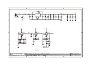
TYPICAL APPLICATIO<br />
U<br />
Laser Temperature Control Loop Achieving Setpoint Stability Approaching 0.01°C<br />
10k<br />
0.1%<br />
10k<br />
NTC<br />
TMP<br />
CMD<br />
REF<br />
LTC1658<br />
V OUT<br />
100k<br />
C1, C2: TAIYO YUDEN JMK325BJ226MM-T (X7R)<br />
L1, L2: CDRH6D2B-220MC<br />
*MNA, MPA: SILICONIX Si9801<br />
**MNB, MPB: SILICONIX Si9801<br />
+<br />
REF<br />
LTC2053<br />
A = 10<br />
–<br />
10M<br />
4.7µF<br />
82k<br />
V DD<br />
V REF<br />
R ILIM2<br />
1µF<br />
R ILIM1<br />
1<br />
2<br />
3<br />
4<br />
5<br />
6<br />
7<br />
8<br />
9<br />
10<br />
11<br />
12<br />
13<br />
14<br />
PLLLPF<br />
R SLEW<br />
SDSYNC<br />
CNTRL<br />
EAOUT<br />
FB<br />
LTC1923<br />
AGND<br />
SS<br />
I LIM<br />
V SET<br />
FAULT<br />
V THRM<br />
H/C<br />
V TEC<br />
28<br />
R T<br />
27<br />
C T<br />
26<br />
V REF<br />
25<br />
PDRVB<br />
24<br />
NDRVB<br />
23<br />
V DD<br />
22<br />
PGND<br />
21<br />
NDRVA<br />
20<br />
PDRVA<br />
19<br />
CS +<br />
18<br />
CS –<br />
17<br />
I TEC<br />
16<br />
TEC +<br />
15<br />
TEC –<br />
V REF<br />
1µF<br />
330pF<br />
10k<br />
1µF<br />
MPA*<br />
L1<br />
10µH<br />
C1<br />
MNB** 22µF<br />
3<br />
4<br />
1<br />
2<br />
R S<br />
V DD<br />
TEC<br />
10µF<br />
+<br />
1923 TA01<br />
47µF<br />
L2<br />
10µH<br />
C2<br />
22µF<br />
MPB**<br />
MNA*<br />
Information furnished by Linear Technology Corporation is believed to be accurate and reliable.<br />
However, no responsibility is assumed for its use. Linear Technology Corporation makes no representation<br />
that the interconnection of its circuits as described herein will not infringe on existing patent rights.<br />
1
LTC1923<br />
ABSOLUTE AXI U RATI GS<br />
(Note 1)<br />
W W W<br />
V DD to GND................................................. –0.3V to 6V<br />
SDSYNC, R SLEW ......................................... –0.3V to 6V<br />
FB, CNTRL, V THRM , I LIM .............................. –0.3V to 6V<br />
CS + , CS – , TEC + , TEC – .................................–0.3V to 6V<br />
FAULT, H/C ................................................. –0.3V to 6V<br />
Operating Temperature Range (Note 2) .. –40°C to 85°C<br />
Storage Temperature Range ................. –65°C to 125°C<br />
Lead Temperature (Soldering, 10 sec).................. 300°C<br />
U<br />
U U W<br />
PACKAGE/ORDER I FOR ATIO<br />
PLLLPF 1<br />
R SLEW 2<br />
SDSYNC 3<br />
CNTRL 4<br />
EAOUT 5<br />
FB 6<br />
AGND 7<br />
SS 8<br />
I LIM 9<br />
V SET 10<br />
FAULT 11<br />
V THRM 12<br />
H/C 13<br />
V TEC 14<br />
TOP VIEW<br />
28 R T<br />
27 C T<br />
26 V REF<br />
25 PDRV B<br />
24 NDRV B<br />
23 V DD<br />
22 PGND<br />
21 NDRV A<br />
20 PDRV A<br />
19 CS +<br />
18 CS –<br />
17 I TEC<br />
16 TEC +<br />
15 TEC –<br />
ORDER PART<br />
NUMBER<br />
LTC1923EGN<br />
GN PACKAGE<br />
28-LEAD PLASTIC SSOP<br />
T JMAX = 125°C, θ JA = 120°C/W<br />
Consult LTC Marketing for parts specified with wider operating temperature<br />
ranges.<br />
ELECTRICAL CHARACTERISTICS<br />
The ● denotes specifications which apply over the full operating temperature range, otherwise specifications are T A = 25°C.<br />
V DD = 5V, R SLEW = V DD , SDSYNC = V DD , R T = 10k, C T = 330pF unless otherwise noted.<br />
SYMBOL PARAMETER CONDITIONS MIN TYP MAX UNITS<br />
Input Supply<br />
UVLO Undervoltage Lockout Low to High Threshold ● 2.6 2.7 V<br />
UVHYST Hysteresis High to Low ● 50 130 mV<br />
I DD Operating Supply Current No Output Load, Outputs Not Switching 2 4 mA<br />
I DDSHDN Shutdown I DD SDSYNC = 0V 10 25 µA<br />
SHDNTH Shutdown Threshold Measured at PDRVA, PDRVB 0.3 0.8 1.4 V<br />
Reference<br />
V REF Reference Output Voltage No Load 2.462 2.5 2.538 V<br />
● 2.450 2.550 V<br />
V REFGD V REF Good Threshold V REF Rising Threshold ● 2.25 2.45 V<br />
LDREG Load Regulation I LOAD = –1mA to –10mA 10 25 mV<br />
LINEREG Line Regulation V DD = 2.7V to 5.5V 5 20 mV<br />
V REFISC Short-Circuit Current V REF = 0V 10 20 mA<br />
Oscillator and Phase-Locked Loop<br />
f OSCI Initial Oscillator Frequency R T = 10k, C T = 330pF 190 225 260 kHz<br />
f OSC Frequency Variation V DD = 2.7V to 5V ● 165 225 270 kHz<br />
OSCPK C T Ramp Peak 1.4 1.5 1.6 V<br />
OSCVLY C T Ramp Valley 0.4 0.5 0.6 V<br />
C TICH C T Charge Current C T = 0.3V, R T = 10k –150 µA<br />
2
ELECTRICAL CHARACTERISTICS<br />
The ● denotes specifications which apply over the full operating temperature range, otherwise specifications are T A = 25°C.<br />
V DD = 5V, R SLEW = V DD , SDSYNC = V DD , R T = 10k, C T = 330pF unless otherwise noted.<br />
LTC1923<br />
SYMBOL PARAMETER CONDITIONS MIN TYP MAX UNITS<br />
C TIDIS C T Discharge Current C T = 1.8V, R T = 10k 150 µA<br />
PLLGAIN Gain from PLLLPF to R T –1.1 –0.9 –0.7 V/V<br />
I PLLLPF<br />
Phase Detector Output Current<br />
Sinking f SYNC < f OSC 12 µA<br />
Sourcing f SYNC > f OSC –12 µA<br />
MSTTH Master Threshold On PLLLPF Pin Measured at SDSYNC Pin V DD – 0.7 V DD – 0.4 V<br />
SDDLY Shutdown Delay to Output 20 45 µs<br />
Error Amplifier<br />
V OS Input <strong>Of</strong>fset Voltage EAOUT = 1V, V CM = 2.5V –18 18 mV<br />
AOL Open-Loop Gain EAOUT = 0.45V to 1.55V, CNTRL = 2.5V 80 dB<br />
V CM Common Mode Input Range EAOUT = 1V 0.2 V DD + 0.2 V<br />
I IB FB and CNTRL Input Bias Currents FB = CNTRL = 1.25 –100 100 nA<br />
V OH Output High I LOAD = –100µA 1.65 V<br />
V OL Output Low I LOAD = 100µA 0.3 0.45 V<br />
I SOURCE Sourcing Current EAOUT = 1V, FB = 1V, CNTRL = 2V –1.5 –0.5 mA<br />
I SINK Sinking Current EAOUT = 1V, FB = 1V, CNTRL = 0V 1 2 mA<br />
GBW Gain-Bandwidth Product f = 100kHz (Note 3) 2 MHz<br />
Current Sense Amplifier<br />
ACS Amplifier Gain 10 V/V<br />
CSOFF Amplifier <strong>Of</strong>fset –15 –2 10 mV<br />
I TECH Output High Voltage I LOAD = –50µA V DD – 0.2 V DD – 0.1 V<br />
I TECL Output Low Voltage I LOAD = 50µA 0.1 0.2 V<br />
f3dB –3dB Frequency (Note 3) 500 kHz<br />
I LIMTH Current Limit Threshold Measured at CS + , CS – ● 125 145 165 mV<br />
I LIMDLY Current Limit Delay to Output 300 450 ns<br />
SSI CHG Soft-Start Charge Current SS = 0.75V –2.5 –1.5 –0.5 µA<br />
SSI LIM Soft-Start Current Limit Threshold SS = 0.5V, Measured at CS + , CS – 50 70 90 mV<br />
I LIM I LIM Current Limit Threshold I LIM = 0.5V, Measured at CS + , CS – 50 70 90 mV<br />
TEC Voltage Amplifier<br />
ATEC Amplifier Gain 0.98 1 1.02 V/V<br />
TECOFF Amplifier <strong>Of</strong>fset Measured at V TEC , V CM = 2.5V –7 mV<br />
TECCMR Common Mode Rejection 0.1V < V CM < 4.9V 60 dB<br />
V TECH Output High Voltage I LOAD = –50µA 4.7 4.9 V<br />
V TECL Output Low Voltage I LOAD = 50µA 0.1 0.3 V<br />
f3dB –3dB Frequency (Note 3) 1 MHz<br />
Output Drivers<br />
OUTH Output High Voltage I OUT = –100mA 4 4.5 V<br />
OUTL Output Low Voltage I OUT = 100mA 0.7 1.2 V<br />
t RISE Output Rise Time C LOAD = 1nF 20 ns<br />
t FALL Output Fall Time C LOAD = 1nF 20 ns<br />
t rSLEW Output Rise Time C LOAD = 1nF, R SLEW = 10k 20 ns<br />
t fSLEW Output Fall Time C LOAD = 1nF, R SLEW = 10k 20 ns<br />
t rSLEW Output Rise Time C LOAD = 1nF, R SLEW = 100k 90 ns<br />
3
LTC1923<br />
ELECTRICAL CHARACTERISTICS<br />
The ● denotes specifications which apply over the full operating temperature range, otherwise specifications are T A = 25°C.<br />
V DD = 5V, R SLEW = V DD , SDSYNC = 5V, R T = 10k, C T = 330pF unless otherwise noted.<br />
SYMBOL PARAMETER CONDITIONS MIN TYP MAX UNITS<br />
t fSLEW Output Slew Fall Time C LOAD = 1nF, R SLEW = 100k 90 ns<br />
SLEWVT R SLEW Disable Threshold 2.75 V<br />
DLY Output Dead Time R T = 10k 90 ns<br />
Fault<br />
OPENTH Open Thermistor Threshold V SET = 5V, Measured with Respect to V SET –350 mV<br />
SHRTTH Shorted Thermistor Threshold V SET = 5V, Measured with Respect to GND 0.975 V<br />
FLTV Fault Output Low Voltage 1mA Into FAULT, During Fault 150 300 mV<br />
Direction Comparator<br />
DIRH Low-to-High Threshold TEC – = 2.5V, Measured with Respect to TEC – 50 mV<br />
Sensed When H/C Toggles Low<br />
DIRL High-to-Low Threshold TEC – = 2.5V, Measured with Respect to TEC – –50 mV<br />
Sensed When H/C Toggles High<br />
HCV H/C Output Low Voltage 1mA Into Pin, TEC + = 2.7V, TEC – = 2.5V 150 300 mV<br />
Note 1: Absolute Maximum Ratings are those values beyond which the life<br />
of a device may be impaired.<br />
Note 2: The LTC1923E is guaranteed to meet specifications from 0°C to<br />
70°C. Specifications over the –40°C to 85°C operating temperature range<br />
are assured by design, characterization and correlation with statistical<br />
process controls.<br />
Note 3: Guaranteed by design, not tested in production.<br />
TYPICAL PERFOR A CE CHARACTERISTICS<br />
OSCILLATOR FREQUENCY (kHz)<br />
265<br />
245<br />
225<br />
205<br />
185<br />
165<br />
–50<br />
UW<br />
Oscillator Frequency<br />
vs Temperature Oscillator Frequency vs R T V REF vs Temperature<br />
–20 10 40 70<br />
TEMPERATURE (°C)<br />
100 130<br />
OSCILLATOR FREQUENCY (kHz)<br />
1800<br />
1600<br />
1400<br />
1200<br />
1000<br />
800<br />
600<br />
400<br />
200<br />
0<br />
5<br />
C T = 68pF<br />
C T = 330pF<br />
C T = 150pF<br />
V DD = 2.75V, 5V<br />
T A = 25°C<br />
10 15<br />
20<br />
R T (kΩ)<br />
V REF (V)<br />
2.510<br />
2.505<br />
2.500<br />
2.495<br />
2.490<br />
2.485<br />
–50 –20 10 40 70 100 130<br />
TEMPERATURE (°C)<br />
1923 G01<br />
1923 G02<br />
1923 G03<br />
4
LTC1923<br />
TYPICAL PERFOR A CE CHARACTERISTICS<br />
UW<br />
V REF (V)<br />
2.515<br />
2.510<br />
2.505<br />
2.500<br />
2.495<br />
2.490<br />
2.485<br />
V REF vs I REF for Different<br />
Temperatures<br />
T A = 25°C<br />
T A = 125°C<br />
DEAD TIME (ns)<br />
150<br />
125<br />
100<br />
75<br />
Output Dead Time vs R T<br />
T A = 25°C<br />
V DD = 2.7V<br />
V DD = 5V<br />
RISE TIME (ns)<br />
Output Rise/Fall Time vs R SLEW<br />
250<br />
T A = 25°C<br />
200<br />
150<br />
100<br />
2.480<br />
2.475<br />
T A = –50°C<br />
50<br />
50<br />
2.470<br />
0<br />
5 10<br />
15<br />
I REF (mA)<br />
25<br />
5<br />
7.5 10 12.5<br />
R T (kΩ)<br />
15<br />
0<br />
0<br />
100 200 300<br />
R SLEW (kΩ)<br />
1923 G04<br />
1923 G05<br />
1923 G06<br />
ERROR AMPLIFIER V IO (mV)<br />
1.5<br />
1.0<br />
0.5<br />
0<br />
–0.5<br />
–1.0<br />
–50<br />
Error Amplifier <strong>Of</strong>fset Voltage<br />
vs Temperature<br />
–20 10 40 70<br />
TEMPERATURE (°C)<br />
100 130<br />
1923 G07<br />
OPEN THERMISTOR THRESHOLD (V)<br />
4.60<br />
4.59<br />
4.58<br />
4.57<br />
4.56<br />
4.55<br />
–50<br />
Open Thermistor Threshold<br />
vs Temperature<br />
V SET = 5V<br />
–20 10 40 70<br />
TEMPERATURE (°C)<br />
100 130<br />
1923 G08<br />
SHORTED THERMISTOR THRESHOLD (V)<br />
1.00<br />
0.99<br />
0.98<br />
0.97<br />
0.96<br />
0.95<br />
–50<br />
Shorted Thermistor Threshold<br />
vs Temperature<br />
V SET = 5V<br />
–20 10 40 70<br />
TEMPERATURE (°C)<br />
100 130<br />
1923 G09<br />
Current Limit Threshold<br />
vs Temperature<br />
System Power Loss<br />
vs TEC Current<br />
TEC Clamp Voltage<br />
vs Temperature<br />
CURRENT LIMIT THRESHOLD (mV)<br />
165<br />
160<br />
155<br />
150<br />
145<br />
140<br />
135<br />
130<br />
POWER LOSS (W)<br />
0.7<br />
0.6<br />
0.5<br />
0.4<br />
0.3<br />
0.2<br />
0.1<br />
T A = 25°C<br />
V DD = 5V<br />
V DD = 3.3V<br />
TEC CLAMP VOLTAGE (V)<br />
2.550<br />
2.530<br />
2.510<br />
2.490<br />
2.470<br />
125<br />
–50<br />
–20 10 40 70 100<br />
TEMPERATURE (°C)<br />
130<br />
0<br />
0<br />
0.5 1<br />
TEC CURRENT (A)<br />
2.450<br />
–50<br />
–20 10 40 70 100<br />
TEMPERATURE (°C)<br />
130<br />
1923 G10<br />
1923 G11<br />
1923 G12<br />
5
LTC1923<br />
TYPICAL PERFOR A CE CHARACTERISTICS<br />
UW<br />
Long-Term Cooling Mode Stability Measured in Environment that Steps 20 Degrees Above Ambient<br />
Every Hour. <strong>Data</strong> Shows Resulting 0.008°C Peak-to-Peak Variation, Indicating Thermal Gain of 2500.<br />
0.0025°C Baseline Tilt Over Plot Length Derives From Varying Ambient Temperature<br />
Identical Test Conditions as Above, Except in Heating Mode. TEC’s Higher Heating Mode Efficiency<br />
Results in Higher Thermal Gain. 0.002°C Peak-to-Peak Variation Is 4x Stability Improvement. Baseline<br />
Tilt, Just Detectable, Shows Similar 4x Improvement vs Above<br />
6
PI FU CTIO S<br />
U U U<br />
PLLLPF (Pin 1): This pin serves as the lowpass filter for<br />
the phase-locked loop when the part is being synchronized.<br />
The average voltage on this pin equally alters both<br />
the oscillator charge and discharge currents, thereby<br />
changing the frequency of operation. Bringing the voltage<br />
on this pin above V DD – 0.4V signifies that the part will be<br />
used as the synchronization master. This allows multiple<br />
devices on the same board to be operated at the same<br />
frequency. The SDSYNC pin will be pulled low during each<br />
C T charging cycle to facilitate synchronization.<br />
R SLEW (Pin 2): Placing a resistor from this pin to AGND<br />
sets the voltage slew rate of the output driver pins. The<br />
minimum resistor value is 10k and the maximum value is<br />
300k. Slew rate limiting can be disabled by tying this pin<br />
to V DD , allowing the outputs to transition at their maximum<br />
rate.<br />
SDSYNC (Pin 3): This pin can be used to disable the IC,<br />
synchronize the internal oscillator or be the master to<br />
synchronize other devices. Grounding this pin will disable<br />
all internal circuitry and cause NDRVA and NDRVB to be<br />
forced low and PDRVA and PDRVB to be forced to V DD .<br />
EAOUT will be forced low. FAULT will also be asserted low<br />
indicating a fault condition. The pin can be pulled low for<br />
up to 20µs without triggering the shutdown circuitry. The<br />
part can either be slaved to an external clock or can be used<br />
as the master (see Applications Information for a more<br />
detailed explanantion).<br />
CNTRL (Pin 4): Noninverting Input to the Error Amplifier.<br />
EAOUT (Pin 5): Output of the Error Amplifier. The loop<br />
compensation network is connected between this pin and<br />
FB. The voltage on this pin is the input to the PWM<br />
comparator and commands anywhere between 0% and<br />
100% duty cycle to control the temperature of the temperature<br />
sense element.<br />
FB (Pin 6): The Inverting Input to the Error Amplifier. This<br />
input is connected to EAOUT through a compensating<br />
feedback network.<br />
AGND (Pin 7): Signal Ground. All voltages are measured<br />
with respect to AGND. Bypass V DD and V REF with low ESR<br />
capacitors to the ground plane near this pin.<br />
LTC1923<br />
SS (Pin 8): The TEC current can be soft-started by adding<br />
a capacitor from this pin to ground. This capacitor will be<br />
charged by a 1.5µA current source. This pin connects to one<br />
of the inverting inputs of the current limit comparator and<br />
allows the TEC current to be linearly ramped up from zero.<br />
The voltage on this pin must be greater than 1.5V to allow<br />
the open/shorted thermistor window comparitor to signal<br />
a fault.<br />
I LIM (Pin 9): A voltage divider from V REF to this pin sets the<br />
current limit threshold for the TEC. If the voltage on this pin<br />
is set higher than 1V, then I LIM = 150mV/R S as that is the<br />
internal current limit comparator level. If the voltage on<br />
this pin is set less than 1V, the current limit value where the<br />
comparator trips is:<br />
I LIM = [0.15 • R ILIM1 • V REF ]/[(R ILIM1 + R ILIM2 ) • R S ]<br />
V SET (Pin 10): This is the input for the setpoint reference<br />
of the temperature sense element divider network or<br />
bridge. This pin must be connected to the bias source for<br />
the thermistor divider network.<br />
FAULT (Pin 11): Open-drain output that indicates by<br />
pulling low when the voltage on V THRM is outside the<br />
specified window, the part is in shutdown, undervoltage<br />
lockout (UVLO), or the reference is not good. When the<br />
voltage on V THRM is outside the specified window, it<br />
signifies that the thermistor impedance is out of its acceptable<br />
range. This signal can be used to flag a microcontroller<br />
to shut the system down or used to disconnect power from<br />
the bridge. See Applications Information for using this<br />
signal for redundant protection.<br />
V THRM (Pin 12): Voltage Across the Thermistor. If the<br />
voltage on this pin is outside the range between 350mV<br />
below V SET and 0.2 • V SET , the FAULT pin will be asserted<br />
(and latched) low indicating that the thermistor temperature<br />
has moved outside the acceptable range.<br />
H/C (Pin 13): This open-drain output provides the direction<br />
information of the TEC current flow. If TEC + is greater<br />
than TEC – , which typically corresponds to the system<br />
cooling, this output will be a logic low. If the opposite is the<br />
case, this pin will pull to a logic high.<br />
7
LTC1923<br />
PI FU CTIO S<br />
U U U<br />
V TEC (Pin 14): Output of the differential TEC voltage<br />
amplifier equal to the magnitude of the voltage across the<br />
TEC.<br />
TEC – (Pin 15): Inverting Input to the Differential TEC<br />
Voltage Amplifier. This amplifier has a fixed gain of 1 with<br />
its output being the voltage across the TEC with respect to<br />
AGND. This input, along with TEC + , signifies whether the<br />
TEC is heating or cooling the laser as indicated by the H/C<br />
pin.<br />
TEC + (Pin 16): Noninverting Input to the Differential TEC<br />
Voltage Amplifier.<br />
I TEC (Pin 17): Output of the Differential Current Sense<br />
Amplifier. The voltage on this pin is approximately equal to<br />
10 • I TEC • R S , where I TEC is the thermoelectric cooler<br />
current and R S is the sense resistor used to sense this<br />
current. This voltage represents only the magnitude of the<br />
current and provides no direction information. Current<br />
limit occurs when the voltage on this pin exceeds the<br />
lesser of 1.5 times the voltage on SS, 1.5 times the voltage<br />
on I LIM or 1.5V. When this condition is present, the pair of<br />
outputs, which are presently conducting, are immediately<br />
turned off. The current limit condition is cleared when the<br />
C T pin reaches the next corresponding peak or valley (see<br />
Current Limit section).<br />
CS – (Pin 18): Inverting Input to the Differential Current<br />
Sense Amplifier.<br />
CS + (Pin 19): Noninverting Input of the Differential Current<br />
Sense Amplifier. The amplifier has a fixed gain of 10.<br />
PDRVA, PDRVB (Pins 20, 25): These push-pull outputs<br />
are configured to drive the opposite high side PMOS<br />
switches in a full-bridge arrangement.<br />
NDRVA, NDRVB (Pins 21, 24): These push-pull outputs<br />
are configured to drive the opposite low side switches in<br />
a full-bridge arrangement.<br />
PGND (Pin 22): This is the high current ground for the IC.<br />
The external current sense resistor should be referenced<br />
to this point.<br />
V DD (Pin 23): Positive Supply Rail for the IC. Bypass this<br />
pin to PGND and AGND with >10µF low ESL, ESR ceramic<br />
capacitors. The turn on voltage level for V DD is 2.6V with<br />
130mV of hysteresis.<br />
V REF (Pin 26): This is the output of the Reference. This pin<br />
should be bypassed to GND with a 1µF ceramic capacitor.<br />
The reference is able to supply a minimum of 10mA of<br />
current and is internally short-circuit current limited.<br />
C T (Pin 27): The triangular wave oscillator timing capacitor<br />
pin is used in conjunction with R T to set the oscillator<br />
frequency. The equation for calculating frequency is:<br />
f<br />
OSC<br />
= 075 . R • C Hz<br />
T<br />
T<br />
R T (Pin 28): A single resistor from R T to AGND sets the<br />
charging and discharging currents for the triangle oscillator.<br />
This pin also sets the dead time between turning one<br />
set of outputs off and turning the other set on to ensure the<br />
outputs do not cross conduct. The voltage on this pin is<br />
regulated to 0.5V. For best performance, the current<br />
sourced from the R T pin should be limited to a maximum<br />
150µA. Selecting R T to be 10k is recommended and<br />
provides 90ns of dead time.<br />
8
– +<br />
–<br />
–<br />
–<br />
+<br />
–<br />
+<br />
–<br />
+<br />
–<br />
+<br />
–<br />
+<br />
–<br />
+<br />
–<br />
+<br />
FU CTIO AL DIAGRA<br />
U U<br />
W<br />
LTC1923<br />
g m<br />
OSCILLATOR<br />
–<br />
+<br />
–<br />
ERROR<br />
AMPLIFIER<br />
+<br />
TEC<br />
CLAMP<br />
2.5V<br />
–<br />
+<br />
–<br />
+<br />
SDSYNC<br />
3<br />
IRT<br />
28<br />
CT<br />
27<br />
FB<br />
6<br />
CNTRL<br />
4<br />
EAOUT<br />
5<br />
VSET<br />
10<br />
12<br />
0.7V<br />
20µs<br />
DELAY<br />
+<br />
–<br />
PHASE<br />
DETECTOR<br />
SHUTDOWN<br />
COMPARATOR<br />
1 = SHDN<br />
PLLLPF<br />
1<br />
VDD – 0.4V<br />
+<br />
–<br />
MASTER<br />
COMPARATOR<br />
R T<br />
0.5V<br />
R<br />
V THRM<br />
DIGITAL<br />
RAMP = 0.5V – 1.5V<br />
VTEC<br />
OPEN/SHORTED THERMISTOR<br />
350mV<br />
S Q<br />
R<br />
TSD<br />
ENABLE<br />
0.2V SET<br />
1.5V<br />
ENABLE<br />
VBG<br />
VDD<br />
1 = REFGOOD<br />
SS<br />
UVLO<br />
2.5V LDO<br />
REF<br />
VREF GOOD<br />
COMPARATOR<br />
1 = UVLO<br />
REFGOOD<br />
UVLO<br />
SHDN<br />
TSD<br />
ENABLE<br />
7<br />
AGND<br />
26<br />
V REF<br />
11<br />
FAULT<br />
S<br />
Q<br />
R<br />
Q<br />
Q<br />
QB<br />
1.25V + VBE<br />
VDD<br />
ISLEW<br />
RSLEW<br />
2<br />
1/2 VDD<br />
SLEW LIMITING<br />
1 = NO SLEW LIMITING<br />
SWITCHES OPEN<br />
Q<br />
S<br />
1V<br />
ENABLE<br />
OSC VALLEY<br />
CURRENT LIMIT<br />
2R<br />
R<br />
X10<br />
INPUT<br />
SELECT<br />
CS AMP<br />
X1<br />
INPUT<br />
SELECT<br />
TEC AMP<br />
17<br />
14<br />
13<br />
I TEC V TEC H/C<br />
DIRECTIONAL<br />
COMPARATOR<br />
NDRVB<br />
24<br />
V DD PGND<br />
22<br />
1.5µA<br />
SS<br />
8<br />
ILIM<br />
9<br />
CS +<br />
19<br />
CS –<br />
18<br />
TEC +<br />
16<br />
TEC –<br />
15<br />
1923 BD<br />
+<br />
–<br />
0.3V<br />
g m<br />
gm<br />
PDRVB<br />
NDRVA<br />
DELAY ∝ I RT<br />
90ns<br />
DELAY<br />
PDRVA<br />
NDRVA<br />
90ns<br />
DELAY<br />
S<br />
QB<br />
Q<br />
R<br />
ENABLE<br />
OSC PEAK<br />
Q<br />
Q<br />
R<br />
Q<br />
VDD<br />
23<br />
PDRVA<br />
20<br />
PDRVB<br />
25<br />
NDRVA<br />
21<br />
9
LTC1923<br />
OPERATIO U<br />
MAIN CONTROL LOOP<br />
The LTC1923 uses a constant frequency, voltage mode<br />
architecture to control temperature. The relative duty<br />
cycles of two pairs of N-/P-channel external MOSFETs, set<br />
up in a full-bridge (also referred to as an H-bridge)<br />
configuration are adjusted to control the system temperature.<br />
The full-bridge architecture facilitates bidirectional<br />
current flow through a thermoelectric cooler (TEC) or<br />
other heating element. The direction of the current flow<br />
determines whether the system is being heated or cooled.<br />
Typically a thermistor, platinum RTD or other appropriate<br />
element is used to sense the system temperature. The<br />
control loop is closed around this sense element and TEC.<br />
The voltage on the output of the error amplifier, EAOUT,<br />
relative to the triangle wave on C T , controls whether the<br />
TEC will be heating or cooling. A schematic of the external<br />
full bridge is shown in Figure 1. The “A” side of the bridge<br />
is comprised of the top left PMOS, MPA, and lower right<br />
NMOS, MNA. The gates of these devices are attached to<br />
the PDRVA and NDRVA outputs of the LTC1923, respectively.<br />
The “B” side of the bridge is comprised of PMOS,<br />
MPB and NMOS, MNB. The gates of these MOSFETs are<br />
controlled by the PDRVB and NDRVB outputs of the<br />
LTC1923.<br />
The “A” side of the bridge is turned on (NDRVA is high and<br />
PDRVA is low) when the output of the error amplifier is<br />
less than the voltage on the C T pin as shown in Figure 2.<br />
For this condition, the state of each output driver is as<br />
follows: PDRVA is low, NDRVA is high, PDRVB is high and<br />
NDRVB is low. When the voltage on EAOUT is greater than<br />
the voltage on the C T pin, the “B” side of the bridge is<br />
turned on. The average voltage across the TEC, V TECOOLER ,<br />
is approximately:<br />
V TECOOLER = V<br />
+ TEC – V<br />
– TEC = V DD •␣ (D A – D B )<br />
where<br />
V DD = the full-bridge supply voltage<br />
V TECOOLER = V<br />
+ TEC – V<br />
– TEC<br />
D A = the duty cycle of the “A” side of the bridge or the<br />
amount of time the “A” side is on divided by the<br />
oscillator period<br />
D B = the duty cycle of the “B” side of the bridge<br />
Duty cycle terms D A and D B are related by the following<br />
equation:<br />
D A = 1 – D B<br />
In steady-state, the polarity of V TECOOLER indicates whether<br />
the system is being heated or cooled. Typically, when<br />
current flows into the TEC + side of the cooler, the system<br />
is being cooled and heated when current flows out of this<br />
terminal. Note: Do not confuse the TEC + side of the TEC<br />
with the TEC + input of the LTC1923, although these two<br />
points should be connected together.<br />
V DD<br />
PDRVB<br />
EAOUT<br />
PDRVA<br />
NDRVB<br />
NDRVA<br />
MPA<br />
MNB<br />
+<br />
V TECOOLER<br />
TEC<br />
–<br />
MPB<br />
C T<br />
NDRVA<br />
A<br />
SIDE<br />
ON<br />
B<br />
SIDE<br />
ON<br />
MNA<br />
PDRVA<br />
CS +<br />
3<br />
1<br />
1923 F01<br />
R S<br />
NDRVB<br />
CS –<br />
TEC +<br />
TEC –<br />
4<br />
2<br />
PDRVB<br />
1923 F02<br />
10<br />
Figure 1. Full-Bridge Schematic<br />
Figure 2. Error Amplifier Output, C T and Output Driver Waveforms
OPERATIO U<br />
LTC1923<br />
PROTECTION FEATURES<br />
Many protection features have been integrated into the<br />
LTC1923 to ensure that the TEC is not overstressed or the<br />
system does not thermally run away. These features<br />
include pulse-by-pulse current limiting, TEC voltage clamping<br />
and open/shorted thermistor detection.<br />
Current Limit<br />
The peak current in the full bridge during each switching<br />
cycle can be limited by placing a sense resistor, R S , from<br />
the common NMOS source connections of MNA and MNB<br />
to ground. The CS + and CS – connections should be made<br />
as shown in Figure 1. Current limit is comprised of a fixed<br />
gain of ten differential amplifier, an attenuator (resistor<br />
divider) and a current limit comparator. A detailed diagram<br />
of the circuitry is shown in Figure 3. The differential<br />
amplifier output, I TEC , is provided to allow the user the<br />
ability to monitor the instantaneous current flowing in the<br />
bridge. If an average current is desired, an external RC<br />
filter can be used to filter the I TEC output. Approximately<br />
50ns of leading edge blanking is also internally integrated<br />
to prevent nuisance tripping of the current sense circuitry.<br />
It relieves the filtering requirements for the CS input pins.<br />
During a switching cycle, current limit occurs when the<br />
voltage on I TEC exceeds the lowest of the following three<br />
conditions: 1) 1.5 times the voltage on the SS pin, 2) 1.5<br />
times the voltage on the I LIM pin or 3) 1.5V. When a<br />
current limit condition is sensed, all four external FETs are<br />
immediately shut off. These devices are turned back on<br />
only after C T reaches the same state (either charging or<br />
discharging) as when the current limit condition occurred.<br />
For instance, if C T is charging when current limit<br />
occurs, the outputs are forced off for the remainder of this<br />
charging time, the entire C T discharge time, and are only<br />
re-enabled when C T reaches its valley voltage and begins<br />
charging again. An analogous sequence of events occurs<br />
if current limit is tripped while C T is being discharged.<br />
The full-bridge current can be soft-started (gradually<br />
increased) by placing a capacitor from the SS pin to<br />
ground. A 1.5µA current is sourced from the chip and will<br />
charge the capacitor. This limits the inrush current at startup<br />
and allows the current delivered to the TEC to be linearly<br />
increased from zero.<br />
The LTC1923 features a dedicated pin, I LIM , to adjust<br />
current limit. If the voltage placed on I LIM is greater than<br />
1V, the default current limit, I LIMIT , is:<br />
I LIMIT = 150mV/R S<br />
where R S = the current sense resistor.<br />
Utilizing the I LIM pin allows the current limit threshold to<br />
be easily set and adjusted (the current limit threshold can<br />
also be adjusted by changing R S ). More importantly, it<br />
facilitates independent setting of the heating and cooling<br />
current limits with the addition of one transistor. Figure 4<br />
shows how to implement this using three resistors and an<br />
external NMOS, M1. In many applications, a higher cooling<br />
capability is desired. When TEC + is greater than<br />
TEC – , the H/C output is in a low state signifying that the<br />
system is being cooled (this is typical for most lasers).<br />
CS +<br />
CS –<br />
I TEC<br />
I LIM<br />
SS<br />
TEC + NDRVA<br />
TEC – NDRVB<br />
INPUT SELECT<br />
1.5µA<br />
+<br />
–<br />
CURRENT SENSE<br />
AMPLIFIER<br />
A = 10<br />
R<br />
2R<br />
NDRVA NDRVB<br />
LEB<br />
1V<br />
+<br />
–<br />
PULSE-BY-PULSE<br />
CURRENT LIMIT<br />
OSCILLATOR<br />
PEAK/VALLEY<br />
S<br />
R<br />
Q<br />
1923 F03<br />
SHUT<br />
OUTPUTS<br />
OFF<br />
Figure 3. Current Sense Circuitry<br />
11
OPERATIO U<br />
LTC1923<br />
Transistor M1 is off and the current limit threshold is given<br />
by:<br />
015 . • RILIM1<br />
• VREF<br />
ILIMIT<br />
=<br />
R + R • R<br />
( )<br />
ILIM1 ILIM2<br />
S<br />
When TEC – is greater than TEC + , the open-drain output,<br />
H/C, pulls high through R PULLUP , causing M1 to turn on.<br />
The current limit value is given by:<br />
I<br />
V REF<br />
LIMIT<br />
R ILIM2<br />
R ILIM1<br />
M1<br />
2N7002<br />
R LIM3<br />
V DD<br />
R PULLUP<br />
H/C<br />
( )<br />
( )<br />
I LIM<br />
LTC1923<br />
TEC +<br />
015 . • RILIM1 RILIM3<br />
• VREF<br />
=<br />
R + R R • R<br />
ILIM2 ILIM1 ILIM3<br />
S<br />
reducing the current limit threshold for heating. If the<br />
heating current limit needs to be greater than the cooling<br />
limit, an extra inversion can be added.<br />
Open/Shorted Thermistor Detection<br />
The temperature sense element (NTC thermistor, platinum<br />
RTD or other appropriate component) must be properly<br />
connected in order for the system to regulate<br />
temperature. If the sense element is incorrectly connected,<br />
the system will be unable to control the temperature<br />
and the potential exists for the system to thermally run<br />
away.<br />
A TEC by nature produces a temperature differential between<br />
opposite sides of the device depending upon how<br />
much current is flowing through it. There is a maximum<br />
limit to the amount of temperature differential that can be<br />
produced, which depends upon a number of physical<br />
+<br />
–<br />
TEC –<br />
1923 F04<br />
Figure 4. Independently Heating/Cooling Current Limit<br />
parameters including the size of the TEC and how well<br />
heatsinked the device is. The TEC itself dissipates power<br />
to produce the temperature differential, generating heat,<br />
which must also be removed. At a certain level of power<br />
dissipation in the TEC, both sides will begin to heat. This<br />
is because the TEC will not be able to pump the selfgenerated<br />
heat to the outside world, which can lead to<br />
thermal runaway. If the device thermally runs away, damage<br />
to the TEC and possibly the components whose<br />
temperature is being regulated will occur.<br />
The LTC1923 contains two dedicated comparators that<br />
directly monitor the voltage on the thermistor. If this<br />
voltage is outside the valid window, a latch is set and the<br />
FAULT pin is asserted low. The output drivers are not shut<br />
off and the control circuitry is not disabled, meaning the<br />
part will continue to try to regulate temperature. It is up to<br />
the user to use the FAULT signal to disable the appropriate<br />
circuitry. There are a couple of ways to do this. The first<br />
way is to have the FAULT signal a system microprocessor<br />
to shut the system down through the SDSYNC pin. Figure␣<br />
5 shows another means of protecting the system.<br />
External NMOS M1 and PMOS M2 have been added along<br />
with two pull-up resistors (RP1 and RP2). M1 and RP2<br />
invert the FAULT signal while M2 acts as a switch in series<br />
with bridge. When no fault is present, the gate of M1 is<br />
V DD V DD<br />
V DD<br />
R P1 R P2<br />
M2<br />
FAULT<br />
M1<br />
PDRVB<br />
PDRVA<br />
TEC<br />
NDRVB<br />
NDRVA<br />
3<br />
CS +<br />
1<br />
R S<br />
CS –<br />
2<br />
4<br />
Figure 5. Redundant Fault Protection<br />
1923 F05<br />
12
OPERATIO U<br />
LTC1923<br />
pulled to V DD forcing the gate of M2 low, which allows the<br />
bridge to operate as described earlier. When a fault occurs<br />
and FAULT is asserted low, M1 is shut off, forcing the gate<br />
of M2 high, shutting that device off. The power path is thus<br />
opened, ensuring no current is delivered to the TEC. M2<br />
wants to have low R DS(ON) (less than the value of R S to<br />
minimize the power losses associated with it). R P1 and<br />
R P2 can be selected on the order of 100k.<br />
The lower comparator threshold level is 20% (twenty<br />
percent) of V SET and the upper comparator threshold level<br />
is 350mV below V SET , where V SET is the voltage applied on<br />
the V SET pin. V SET is typically tied to the bias source for the<br />
thermistor divider so that any variations will track out.<br />
The V SET pin has a high input impedance so that a divideddown<br />
voltage can be supplied to this pin to modify the<br />
acceptable thermistor impedance range. This is shown in<br />
Figure 6. The voltage applied to the V SET pin must be a<br />
minimum of 2V. The lower thermistor impedance threshold<br />
is:<br />
R<br />
TH( LOWER)<br />
02 . • R1•<br />
R3<br />
=<br />
R2+<br />
0. 8•<br />
R3<br />
The upper impedance threshold is:<br />
R<br />
TH( UPPER)<br />
( )<br />
R1R3– α( R2+<br />
R3)<br />
=<br />
R2+ α( R2+<br />
R3)<br />
where α = 0.35/V SET .<br />
Changing R1 also changes the valid thermistor impedance<br />
range.<br />
Example: V REF = V SET = 2.5V<br />
R1 = 10k, R2 = 0Ω, R3 = open<br />
V REF<br />
R1<br />
R2<br />
R TH<br />
10k<br />
NTC<br />
V SET<br />
V THRM<br />
1923 F06<br />
Figure 6. Modifying the Acceptable Thermistor Range<br />
R3<br />
R TH = 10k NTC thermistor with a temperature coefficient<br />
of –4.4%/C at 25°C.<br />
The acceptable thermistor impedance range before causing<br />
a fault is 2.5kΩ to 61kΩ. This corresponds to a valid<br />
temperature range of between about –10°C and 60°C.<br />
To ensure the part does not power up into a FAULT at startup,<br />
a FAULT will not be latched until soft-start has completed.<br />
This corresponds to the voltage on SS reaching<br />
1.5V. For a 1µF soft-start capacitor, this delay is approximately<br />
1 second. This provides enough time for all supplies<br />
(V DD , setpoint reference and V REF ) to settle at their<br />
final values.<br />
TEC Voltage Clamping<br />
An internal clamp circuit is included to protect the TEC<br />
from an overvoltage condition. When the differential voltage<br />
across the TEC exceeds 2.5V, the error amplifier<br />
output voltage at the input of the PWM comparator is<br />
limited. This clamps the duty cycle of the output drivers,<br />
and therefore, the voltage across the TEC. The voltage<br />
where clamping occurs can be increased by placing a<br />
resistor divider in parallel with the TEC and by making the<br />
appropriate connections to TEC + and TEC – as shown in<br />
Figure 7. The divider increases the voltage across the TEC,<br />
V TECOOLER , where the clamp activates, to:<br />
V<br />
TECOOLER<br />
⎛ RTE1<br />
RTE<br />
⎞<br />
⎜1+ + ⎟ • 25 . – V<br />
⎝ RTE2<br />
100k<br />
⎠<br />
=<br />
RTE1<br />
1+<br />
200 k<br />
⎛ RTE<br />
⎞<br />
⎜ ⎟<br />
⎝ 200k<br />
⎠<br />
1 1<br />
CM<br />
The terms containing the fixed resistance values are the<br />
loading errors introduced by the input impedance of the<br />
differential amplifier. A common mode voltage error is<br />
also introduced since the addition of R TE1 and R TE2 change<br />
the fully differential nature of the amplifier. In order to<br />
TEC<br />
TEC + R TE2 R TE1<br />
TEC –<br />
V TECOOLER<br />
+ –<br />
1923 F07<br />
V CM<br />
Figure 7. Increasing Voltage Clamp Threshold<br />
13
OPERATIO U<br />
LTC1923<br />
minimize these errors select R TE1 and R TE2 to be 10k or<br />
less. The above equation reduces to:<br />
V<br />
TECOOLER<br />
⎛ RTE1<br />
⎞<br />
≅ ⎜1+<br />
⎟ 2.<br />
5<br />
⎝ R ⎠<br />
TE2<br />
The Higher Voltage Applications section shows a fully<br />
differential means to increase the clamp voltage.<br />
This will similarly alter the heating and cooling direction<br />
thresholds by the same factor, increasing the thresholds<br />
to (R TE1 and R TE2 are assumed to be ≤10k):<br />
⎛ R<br />
DIRH = 50mV⎜1+<br />
⎝ R<br />
⎛ R<br />
DIRL = – 50mV⎜1+<br />
⎝ R<br />
TE1<br />
TE2<br />
⎞<br />
⎟<br />
⎠<br />
TE1<br />
TE2<br />
The output voltage on the VTEC pin, V VTEC , will be reduced<br />
by the same ratio:<br />
V<br />
VTEC<br />
V<br />
=<br />
R<br />
1+<br />
R<br />
TECOOLER<br />
TE1<br />
TE2<br />
Oscillator Frequency<br />
The oscillator determines the switching frequency and the<br />
fundamental positioning of all harmonics. The switching<br />
frequency also affects the size of the inductor that needs<br />
to be selected for a given inductor ripple current (as<br />
opposed to TEC ripple current which is a function of both<br />
the filter inductor and capacitor). A higher switching<br />
frequency allows a smaller valued inductor for a given<br />
ripple current. The oscillator is a triangle wave design. A<br />
current defined by external resistor R T is used to charge<br />
and discharge the capacitor C T . The charge and discharge<br />
rates are equal. The selection of high quality external<br />
components (5% or better multilayer NPO or X7R ceramic<br />
capacitor) is important to ensure oscillator frequency<br />
stability.<br />
The frequency of oscillation is determined by:<br />
f OSC(kHz) = 750 • 10 6 /[R T (kΩ) • C T (pF)]<br />
⎞<br />
⎟<br />
⎠<br />
The LTC1923 can run at frequencies up to 1MHz. The value<br />
selected for R T will also affect the delay time between one<br />
side of the full bridge turning off and the opposite side<br />
turning on. This time is also known as the “break-beforemake”<br />
time. The typical value of 10kΩ will produce a 90ns<br />
“break-before-make” time. For higher frequency applications,<br />
a smaller value of R T may be required to reduce this<br />
delay time. For applications where significant slew rate<br />
limiting or external gate driver chips are used, a higher<br />
value for R T may necessary, increasing the dead time. The<br />
“break-before-make” time can be approximately calculated<br />
by:<br />
t DELAY = R T (kΩ) • 5.75 • 10 –9 + 35ns<br />
Phase-Locked Loop<br />
The LTC1923 has an internal voltage-controlled oscillator<br />
(VCO) and phase detector comprising a phase-locked<br />
loop. This allows the oscillator to be synchronized with<br />
another oscillator by slaving it to a master through the<br />
SDSYNC pin. The part can also be designated as the<br />
master by pulling the PLLLPF pin high to V DD . This will<br />
result in the part toggling the SDSYNC pin at its set<br />
oscillator frequency. This signal can then be used to<br />
synchronize additional oscillators.<br />
When being slaved to another oscillator, the frequency<br />
should be set 20% to 30% lower than the target frequency.<br />
The frequency lock range is approximately ±50%.<br />
The phase detector is an edge sensitive digital type, which<br />
provides zero degrees phase shift between the external<br />
and internal oscillators. This detector will not lock up on<br />
input frequencies close to the harmonics of the VCO center<br />
frequency. The VCO hold-in range is equal to the capture<br />
range dfH = dfC = ±0.5f O .<br />
The output of the phase detector is a complementary pair<br />
of current sources charging or discharging the external<br />
filter network on the PLLLPF pin. A simplified block<br />
diagram is shown in Figure 8.<br />
If the external frequency (f PLLIN ) is greater than the oscillator<br />
frequency, current is sourced continuously out of the<br />
PLLLPF pin. When the external frequency is less than the<br />
oscillator frequency, current is sunk by the PLLLPF pin.<br />
The loop filter components R LP , C LP and C LP2 , smooth out<br />
14
LTC1923<br />
APPLICATIO S I FOR ATIO<br />
U W U U<br />
current pulses from the phase detector and provide a<br />
stable input to the VCO. These components also determine<br />
how fast the loop acquires lock. In most instances C LP can<br />
be omitted, R LP can be set to 1k and C LP2 can be selected<br />
to be 0.01µF to 0.1µF to stabilize the loop. Make sure that<br />
the low side of filter components is tied to AGND to keep<br />
unwanted switching noise from altering the performance<br />
of the PLL.<br />
As mentioned earlier, one LTC1923 can be used as a<br />
master to synchronize other LTC1923s or additional<br />
devices requiring synchronization. To implement this,<br />
determine the values of R T and C T to obtain the desired<br />
free-running oscillator frequency of the master by using<br />
the equation given in the oscillator frequency section. Tie<br />
the PLLLPF pin of the master to V DD through a resistor<br />
R PLL as shown in Figure 8. R PLL typically can be set to 10k,<br />
but may need to be less if higher frequency operation is<br />
desired (above 250kHz). Set the slave free-running frequencies<br />
to be 20% to 30% less than this. The SDSYNC<br />
pin of the master will switch at its free-running frequency<br />
(with approximately 50% duty cycle), and this can be<br />
used to synchronize the other devices.<br />
V DD<br />
V DD<br />
EXTERNAL<br />
FREQUENCY<br />
R PLL<br />
SDSYNCB<br />
DIGITAL<br />
PHASE<br />
FREQUENCY<br />
DETECTOR<br />
PLLLPF<br />
R T<br />
OSC C T<br />
R LP<br />
C LP C LP2<br />
1923 F08<br />
Figure 8. Phase-Locked Loop Block Diagram<br />
APPLICATIO S I FOR ATIO<br />
U W U U<br />
The thermistor may be isolated from the control circuitry.<br />
It has a relatively high input impedance and is therefore<br />
susceptible to noise pick up. Extreme care should be taken<br />
to ensure this signal is noise free by shielding the line<br />
(coaxially). A lowpass filter can be added between the<br />
thermistor and the input to the LTC2053, but since it is in<br />
the signal path, there are limitations on how much can be<br />
added.<br />
Inductor Ripple Current<br />
The current that flows in the bridge can be separated into<br />
two components, the DC current that flows through the<br />
TEC and the inductor ripple current that is present due to<br />
the switchmode nature of the controller. Although the TEC<br />
current has its own ripple component, proper filtering will<br />
minimize this ripple relative to the inductor ripple current,<br />
validating this assumption that the TEC current is constant<br />
(see TEC Ripple Current section). A simplified half-circuit<br />
of the bridge in steady-state is shown in Figure 9. The<br />
current, I L , through the inductor (L) consists of the ripple<br />
current (∆I 1 ) and static TEC current (I TEC ). The ripple<br />
current magnitude, ∆I 1 , can be calculated using the following<br />
equation:<br />
∆I 1 = (V<br />
2 BRIDGE – V 2 TEC )/(4 • f OSC • L • V BRIDGE )<br />
where<br />
V BRIDGE is the full-bridge supply voltage (typically V DD )<br />
f OSC is the oscillator frequency<br />
L is the filter inductor value<br />
V TEC is the DC voltage drop across the TEC<br />
15
LTC1923<br />
APPLICATIO S I FOR ATIO<br />
16<br />
PDRVA<br />
NDRVB<br />
U W U U<br />
V BRIDGE<br />
MPA<br />
MNB<br />
I L<br />
L<br />
The peak inductor current is equal to I TEC + ∆I 1 /2 and is<br />
the current level that trips the current limit comparator.<br />
Keeping the ripple current component small relative to<br />
I TEC keeps the current limit trip level equal to the current<br />
flowing through the TEC.<br />
Example: V BRIDGE = 5V, R TEC = 2.5Ω, V TEC = 2.5V,<br />
I TEC = 1A, L = 22µH, f OSC = 250kHz. The peak-to-peak<br />
ripple current using the above equation is:<br />
∆I 1 = 170mA<br />
The peak inductor current is therefore 1.085A in order to<br />
get 1A of DC TEC current.<br />
TEC Ripple Current<br />
Every TEC has a fundamental limitation (based mainly on<br />
the TEC’s physical characteristics) on the maximum<br />
temperature differential that it can create between sides.<br />
The ability to create this maximum temperature differential<br />
is affected by the amount of ripple current that flows<br />
through the device, relative to the DC component. An<br />
approximation of this degradation due to TEC ripple current<br />
is given by the following equation:<br />
dT/dT MAX = 1/(1 + N 2 )<br />
where:<br />
dT is the adjusted achievable temperature differential<br />
dT MAX is the maximum possible temperature differential<br />
when the TEC is fed strictly by DC current and is<br />
typically specified by the manufacturer<br />
N is the ratio of TEC ripple current to DC current<br />
TEC manufacturers typically state that N should be no<br />
greater than 10%.<br />
ESR<br />
C<br />
I TEC<br />
+<br />
TEC<br />
1/2 V BRIDGE<br />
1923 F09<br />
Figure 9. Full-Bridge Half Circuit<br />
V TEC /2<br />
In this application, the bridge supply voltage, oscillator<br />
frequency and external filter components determine the<br />
amount of ripple current that flows through the TEC.<br />
Higher valued filter components reduce the amount of<br />
ripple current through the TEC at the expense of increased<br />
board area. Filter capacitor ESR along with inductor ripple<br />
current will determine the peak-to-peak voltage ripple<br />
across the TEC and therefore the ripple current since the<br />
TEC appears resistive.<br />
The ripple current through the TEC, I TEC(RIPPLE) , is<br />
approximately equal to:<br />
I<br />
TEC( RIPPLE)<br />
2 2<br />
VBRIDGE<br />
– VTEC<br />
≅<br />
2<br />
16 • f • L• C• R • V<br />
OSC TEC BRIDGE<br />
2<br />
BRIDGE<br />
2<br />
TEC<br />
V – V • ESR<br />
+ ( )<br />
2 • f • L• V • R<br />
OSC BRIDGE TEC<br />
where:<br />
f OSC = the oscillator frequency<br />
L = the filter inductor value<br />
C = the filter capacitor value<br />
R TEC = the resistance of the TEC<br />
V TEC = the DC voltage drop across the TEC<br />
ESR = the equivalent series resistance of the filter<br />
capacitor<br />
V BRIDGE = the full-bridge supply voltage typically equal<br />
to V DD<br />
The equation above shows that there are two components,<br />
which comprise TEC ripple current. The first term is the<br />
increase in voltage from the charging of the filter capacitor.<br />
The second term is due to the filter capacitor ESR and<br />
is typically the dominant contributor. Therefore the filter<br />
capacitor selected wants to have a low ESR. This capacitor<br />
can be made of multilevel ceramic, OS-CON electrolytic or<br />
other suitable capacitor. Increasing the oscillator frequency<br />
will also reduce the TEC ripple current since both<br />
terms have an inverse relationship to operating frequency.<br />
Example: V BRIDGE = 5V, R TEC = 2.5Ω, V TEC = 2.5V,<br />
L = 22µH, C = 22µF, f OSC = 250kHz, ESR = 100mΩ<br />
I TEC(RIPPLE) = 3.1mA + 13.6mA = 16.7mA
LTC1923<br />
APPLICATIO S I FOR ATIO<br />
U W U U<br />
For this example the DC current flowing through the TEC<br />
is 1A, making the ripple current equal to approximately 1.7%<br />
(this illustrates why I TEC can be approximated to be DC).<br />
Closing the Feedback Loop<br />
Closing the feedback loop around the TEC and thermistor<br />
(or other temperature sensitive element) involves identifying<br />
where the thermal system’s poles are located and<br />
placing electrical pole(s) (and zeroes) to stabilize the<br />
control loop. High DC loop gain is desirable to keep<br />
extremely tight control on the system temperature. Unfortunately<br />
the higher the desired loop gain, the larger the<br />
compensation values required to stabilize the system.<br />
Given the inherently slow time constants associated with<br />
thermal systems (on the order of many seconds), this can<br />
lead to unreasonably large component values. Therefore,<br />
the amount of loop gain necessary to maintain the desired<br />
temperature accuracy should be calculated, and after<br />
adding some margin, this should be the target DC loop<br />
gain for the system. A block diagram of the system is<br />
shown in Figure10. The gain blocks are as follows:<br />
K IA = instrumentation amplifier gain (V/V)<br />
K EA = error amplifier gain (V/V)<br />
K MOD = modulator gain (d/V)<br />
K PWR = power stage gain (V/d)<br />
K TEC = TEC gain (°C/V)<br />
K THRM = Thermistor Gain (V/°C)<br />
K IA and K EA are the electrical gains associated with the<br />
instrumentation and LTC1923 error amplifier. Switching<br />
regulators are sampled systems that convert voltage to<br />
duty cycle (d), which explains why the K MOD and K PWR<br />
gain terms are expressed as a function of duty cycle and<br />
voltage. The TEC converts voltage to temperature change,<br />
while the thermistor’s impedance and therefore voltage<br />
across it changes with temperature.<br />
The loop gain can be expressed by the following equation:<br />
T (loop gain) = K IA • K EA • K MOD • K PWR • K TEC • K THRM<br />
And the error introduced by the finite gain of the system,<br />
V E , can be expressed by:<br />
V E = V IN /(1 + T)<br />
This voltage error translates back into a temperature<br />
setpoint error.<br />
Example:<br />
R THRM = 10k<br />
NTC with 4.4%/°C at 25°C<br />
R1 = 10k<br />
V REF = 2.5V<br />
T = 25°C<br />
For this thermistor with a 25°C temperature setpoint, the<br />
change in thermistor voltage with temperature is given by<br />
–25mV/°C. In order to maintain a 0.01°C temperature<br />
accuracy, this translates into a 250µV error signal, V E . The<br />
K THRM K IA K EA K MOD K PWR K TEC<br />
V REF<br />
V TECOOLER<br />
R1<br />
10k<br />
10k<br />
NTC<br />
+<br />
V E<br />
–<br />
V IN<br />
+<br />
–<br />
LTC2053<br />
R A<br />
LTC1923<br />
+<br />
ERROR<br />
AMP<br />
–<br />
C T<br />
+<br />
–<br />
POWER<br />
STAGE<br />
+<br />
TEC<br />
1923 F10<br />
R F<br />
C F<br />
Figure 10. Simplified Loop Block Diagram<br />
17
LTC1923<br />
APPLICATIO S I FOR ATIO<br />
minimum loop gain can now be calculated from the above<br />
equation:<br />
V E = V IN /(1 + T)<br />
A 25°C setpoint temperature requires V IN = 1.25V for<br />
V REF = 2.5V. The required loop gain is 5000 or 74dB.<br />
There are two handles to adjust the loop gain, K IA and K EA ,<br />
while the other handles are fixed and depend upon the TEC<br />
and thermistor characteristics (K TEC and K THRM ), V SET and<br />
R1 (K THRM ) and V DD (K MOD and K PWR ). The modulator and<br />
power gain product is given by:<br />
K MOD • K PWR = 2 • V DD /V CT = 2 • V DD<br />
where V CT = the C T voltage which has a fixed 1V amplitude.<br />
The TEC gain depends upon the TEC selected and corresponds<br />
to the relationship between the voltage across the<br />
device and what temperature differential is created. This<br />
gain term changes with operating temperature, and whether<br />
the TEC is heating or cooling. TECs are inherently more<br />
efficient at heating (and therefore have a higher gain) as<br />
compared to cooling. A worst-case rough estimation of<br />
the gain can be obtained by taking the maximum TEC<br />
voltage required to force a given change in temperature<br />
from the TEC specifications:<br />
K TEC = dT/V TEC(MAX)<br />
The thermistor gain should be linearized around temperature<br />
setpoint.<br />
Example:<br />
Setpoint T = 25°C<br />
V DD = 5V<br />
R THRM = 10k NTC with 4.4%/°C at 25°C<br />
R1 = 10k<br />
V REF = 2.5V<br />
dT/V TEC(MAX) = 45°C/1.5V = 30°C/V<br />
The linearized thermistor gain around 25°C is – 25mV/°C.<br />
For a minimum loop gain of 5000 as calculated above, the<br />
combined gain of the instrumentation and error amplifiers<br />
can be calculated:<br />
K IA • K EA = T/(K MOD • K PWR • K TEC • K THRM )<br />
K IA • K EA = 5000/(10 • 30 • 0.025) = 667<br />
18<br />
U W U U<br />
A combined gain of 1000 can be selected to provide<br />
adequate margin. The instrumentation amplifier gain should<br />
be set at typically 10, as this attenuates any errors by its<br />
gain factor. The error amplifier gain would then be limited<br />
to the remainder through the gain setting resistors, R F and<br />
R A shown in Figure 10.<br />
R F /R A = KEA – 1<br />
The multiple poles associated with the TEC/thermistor<br />
system makes it difficult to compensate. Compounding<br />
this problem is that there will be significant variations in<br />
thermal time constants for the same system, making<br />
elaborate compensation schemes difficult to reliably implement.<br />
The most robust method (i.e., least prone to<br />
oscillation) is to place a dominant pole well below the<br />
thermal system time constant (τ) (anywhere from many<br />
seconds to minutes). This time constant will set the<br />
capacitor value by the following equation:<br />
C F = τ/R F<br />
Please refer to Application Note 89 for more detailed<br />
information on compensating the loop. Ceramic capacitors<br />
are not recommended for use as the integrating<br />
capacitor or anywhere in the signal path as they exhibit a<br />
piezoelectric effect which can introduce noise into the<br />
system. The component values shown on the front page of<br />
this data sheet provide a good starting point, but some<br />
adjustment may be required to optimize the response.<br />
Dominant pole compensation does have its limitations. It<br />
provides good loop response over a wide range of laser<br />
module types. It does not provide the fastest transient<br />
response to step changes in temperature. If this is a<br />
necessity, a more complex compensation approach as<br />
shown in Figure 11 may be required. This approach adds<br />
an additional zero into the feedback loop to speed up the<br />
transient response. First note that the LTC2053 inputs<br />
have been swapped as the LTC1923 error amplifier is now<br />
running in an inverting configuration. Capacitor C A is<br />
needed to provide the lead term. Resistor R C is used to<br />
buffer the LTC2053 from capacitive loading and limit the<br />
error amplifier high frequency gain.<br />
Since the system thermal pole locations are not known, a<br />
qualitative compensation approach must be employed.<br />
This entails looking at the transient response when the
LTC1923<br />
APPLICATIO S I FOR ATIO<br />
U W U U<br />
C C<br />
TMP<br />
CMD<br />
REF<br />
LTC1658<br />
V OUT<br />
10k<br />
NTC<br />
10k<br />
+<br />
–<br />
LTC2053<br />
REF<br />
A = 10<br />
C A<br />
R B<br />
C B<br />
R C R A<br />
6 –<br />
FB<br />
LTC1923<br />
4 +<br />
ERROR<br />
CNTRL<br />
AMPLIFIER<br />
5<br />
EAOUT<br />
1923 F11<br />
Figure 11. Alternative Compensation Method to Improve Transient Response<br />
TEC is heating (due to the inherent higher gain) for a smallsignal<br />
step change in temperature and modifying compensation<br />
components to improve the response. A reasonable<br />
starting point is to select components that mimic the<br />
response that will be obtained from the front page of this<br />
data sheet. Therefore R A , R B and C B would be selected to<br />
be 1MΩ, 1MΩ and 0.47µF, respectively. R C should be<br />
selected to be a factor of 100 smaller than R A , or on the<br />
order of 10k. Make sure that the loop is stable prior to the<br />
introduction of capacitor C A . The addition of C A will<br />
provide some phase boost in the loop (in effect, offsetting<br />
one of the poles associated with the thermal system). Start<br />
with C A on the order of C B and note its affect on system<br />
response. Adjust the values based on observing whether<br />
the transient response was improved or not with the goal<br />
of reducing C B to improve settling time. As the system<br />
thermal poles can vary between “identical” laser modules<br />
(i.e., same manufacturer and model), care must be taken<br />
to ensure that the values selected provide the desired<br />
response even with these thermal term variations. Compensation<br />
should also be tailored for each unique laser<br />
module as thermal terms can vary significantly between<br />
different brands. C C rolls off high frequency gain , minimizing<br />
noise in the outputs. It is typically about 25 times<br />
smaller than C B . C A , C B and C C should be film capacitors.<br />
Temperature Stability<br />
It is important to differentiate between temperature accuracy<br />
and stability. Since each laser’s output maximizes at<br />
some temperature, temperature setpoint is typically<br />
incremented until this peak is achieved. After this, only<br />
temperature stability is required. The predominant parameters<br />
which affect temperature stability are the thermistor,<br />
the thermistor biasing resistor and any offset drift of the<br />
front-end electrical circuitry. Sufficient loop gain ensures<br />
that any downstream variations do not contribute significantly<br />
to temperature stability. The relatively mild operating<br />
conditions inside the laser module promote good longterm<br />
thermistor stability. A high quality, low temperature<br />
coefficient resistor should be selected to bias the thermistor.<br />
If the 10k resistor has a 100ppm/°C temperature<br />
coefficient, this translates into a 0.18°C setpoint temperature<br />
differential over a 0°C to 70°C ambient for a desired<br />
25°C laser setpoint. Depending upon the temperature<br />
stability requirements of the system, this is very significant.<br />
A lower temperature coefficient resistor may therefore<br />
be desired. The LTC2053 has maximum offset drift to<br />
50nV/°C which translates into less than 0.001°C change<br />
for a 0°C to 70°C ambient.<br />
The offset drift of the LTC1923 error amplifier divided by<br />
the gain of the LTC2053 also affects temperature stability.<br />
The offset drift of the LTC1923 (see characteristic curves)<br />
is typically 1mV over a 0°C to 70°C ambient. After attenuation<br />
by the LTC2053 gain, this translates into a temperature<br />
setpoint variation of 0.004°C. Neither of these offsets<br />
drifts significantly with aging. Depending upon the setpoint<br />
temperature stability requirements of the system, the<br />
LTC2053 instrumentation amplifier may not be necessary.<br />
Figure 12 shows a simplified schematic with the LTC2053<br />
omitted.<br />
Noise and Slew Rate Control<br />
One disadvantage of switching regulators is that the<br />
switching creates wideband harmonic energy. The high<br />
frequency content can pose problems to associated circuitry.<br />
To combat this issue, the LTC1923 offers a pin<br />
19
LTC1923<br />
APPLICATIO S I FOR ATIO<br />
U W U U<br />
10k<br />
10k<br />
NTC<br />
TMP<br />
CMD<br />
REF<br />
LTC1658<br />
V OUT<br />
100k<br />
10M<br />
CNTRL<br />
4<br />
FB<br />
6<br />
4.7µF<br />
+<br />
–<br />
LTC1923<br />
ERROR<br />
AMPLIFIER<br />
EAOUT<br />
5<br />
1923 F12<br />
Figure 12. Simplifed Temperature Control Loop Omitting<br />
the LTC2053 Instrumentation Amplifier Front End<br />
called R SLEW that controls the slew rate of the output drive<br />
waveforms. Slowing down the transition interval reduces<br />
the harmonic frequency content by spreading out the<br />
energy over a longer time period. The additional transition<br />
time causes some efficiency loss (on the order of 2% to<br />
3%) but significantly improves the high frequency noise<br />
reflected onto the input supply.<br />
Slew rate control is engaged by placing a resistor from<br />
R SLEW to AGND. If slew rate control is not desired, the R SLEW<br />
pin should be tied to V DD allowing the output drivers to<br />
transition at their fastest rate. The resistor value should be<br />
set between 10k (fastest transition) and 300k (slowest transition).<br />
This provides about a 10:1 slew rate range to optimize<br />
noise performance. The “break-before-make” time<br />
may need to be increased if slew control is implemented,<br />
especially for slower transition rates. Adjustment can be<br />
done by increasing the value of R T (C T can be reduced to<br />
maintain the same frequency of operation), to ensure that<br />
the bridge MOSFETs receive nonoverlapping drive.<br />
Power MOSFET Selection<br />
Four external MOSFETs must be selected for use with the<br />
LTC1923; a pair of N-channel MOSFETs for the bottom of<br />
the bridge and a pair of P-channel MOSFETs for the top<br />
diagonals of the bridge. The MOSFETs should be selected<br />
for their R DS(ON) , gate charge and maximum V DS, V GS<br />
ratings. A maximum V DS rating of 20V is more than<br />
sufficient for 5V and 12V bridge applications, but as<br />
mentioned in the High Voltage Application section, a 12V<br />
maximum V GS rating is insufficient and higher voltage<br />
MOSFETs must be selected. There is a trade-off between<br />
R DS(ON) and gate charge. The R DS(ON) affects the conduction<br />
losses (I TEC<br />
2<br />
• R DS(ON) ), while gate charge is a<br />
dominant contributor to switching losses. A higher R DS(ON)<br />
MOSFET typically has a smaller gate capacitance and thus<br />
requires less current to charge the gate for the same<br />
BV DSS . For 1A TEC applications, the Si9801DY or Si9928DY<br />
complimentary N- and P-channel MOSFETs provide a<br />
good trade-off between switching and conduction losses.<br />
Above this TEC current level the MOSFETs selected should<br />
have lower R DS(ON) to maintain the high end efficiency.<br />
Efficiency Considerations<br />
Unlike typical voltage regulators, where the output voltage<br />
is fixed, independent of load current, the output voltage of<br />
this regulator changes with load current. This is because<br />
the TEC appears resistive and the current through the TEC<br />
sets the voltage. The output power of the regulator is<br />
defined as:<br />
P OUT = I<br />
2 TEC • R TEC<br />
The efficiency of a switching regulator is equal to the<br />
output power divided by the input power times 100%.<br />
<strong>Of</strong>ten it is useful to analyze individual losses to determine<br />
what is limiting the efficiency and which change would<br />
produce the most significant improvement. Efficiency can<br />
be expressed as:<br />
Efficiency = 100% – (L1 + L2 + L3 + …)<br />
where L1, L2, etc. are the individual losses as a percentage<br />
of input power.<br />
20
LTC1923<br />
APPLICATIO S I FOR ATIO<br />
U W U U<br />
For this application, the main efficiency concern is typically<br />
at the high end of output power. A higher power loss<br />
translates into a greater system temperature rise, resulting<br />
in the need for heat sinking, increasing both the system<br />
size and cost.<br />
There are three main sources which usually account for<br />
most of the losses in the application shown on the front<br />
page of the data sheet: Input supply current, MOSFET<br />
switching losses and I 2 R losses.<br />
1) The input supply current is comprised of the quiescent<br />
current draw from the LTC1658, LTC2053, LTC1923 and<br />
any additional circuitry added. The total maximum supply<br />
current for these devices is on the order of 5mA, which<br />
gives a total power dissipation of 25mW. This power loss<br />
is independent of TEC current.<br />
2) The MOSFET driver current results from switching the<br />
gate capacitance of the power MOSFETs. Each time a gate<br />
is switched from low to high to low again, a packet of<br />
charge dQ moves from V DD to ground. The gate charging<br />
current, I GATECHG = 2 • f • (Q P + Q N ), where Q P and Q N are<br />
the total gate charges of the NMOS and PMOS on one side<br />
of the bridge, and f is the oscillator frequency. The factor<br />
of 2 arises from there being two sets of MOSFETs that<br />
make up the full bridge. Note that increasing the switching<br />
frequency will increase the dynamic current and therefore<br />
power dissipation by the same factor. This power loss is<br />
independent of TEC current.<br />
Example: Q N = 10nC max, Q P = 15nC max, f = 225kHz,<br />
V DD = 5V<br />
Power loss = 2 • f • (Q P + Q N ) • V DD = 56mW<br />
3) The DC resistances of the external bridge MOSFETs,<br />
filter inductors and sense resistor are typically the dominant<br />
loss mechanism at the high end TEC current. The<br />
conduction path of the current includes one NMOS, one<br />
PMOS, two inductors and the sense resistor so the DC<br />
resistances associated with the components dissipate<br />
power.<br />
Example:<br />
R DS(ON)NMOS at 5V = 0.055Ω max<br />
R DS(ON)PMOS at 5V = 0.08Ω max<br />
R S = 0.1Ω<br />
R L = 0.1Ω,<br />
I TEC = 1A<br />
R TEC = 2.5Ω<br />
Total series resistance = 0.055 + 0.08 + 2 • 0.1 + 0.1<br />
= 0.435Ω<br />
Power Loss = (1A) 2 • 0.435Ω = 0.435W<br />
Output Power = (1A) 2 • 2.5Ω = 2.5W<br />
This represents a 17% efficiency loss due to conduction<br />
losses. The other two power loss mechanisms comprise<br />
a little more than a 3% efficiency loss at this output power<br />
level. This may sound alarming if electrical efficiency is the<br />
primary concern and can be easily improved by choosing<br />
lower R DS(ON) MOSFETs, lower series resistance inductors<br />
and a smaller valued sense resistor. If temperature<br />
rise is the primary concern, this power dissipation may be<br />
acceptable. At higher current levels, this example does<br />
illustrate that lower resistance components should be<br />
selected.<br />
Low Voltage Requirements<br />
All components shown on the front page of this data sheet<br />
will operate with a 2.7V input supply. Minor modifications<br />
are required to guarantee correct operation. The voltage<br />
on the REF input of the LTC2053 should be at least 1V<br />
below V DD . Figure 13 shows how to implement this. By<br />
dividing down the 2.5V reference with 500Ω of impedance,<br />
feeding this to the REF input of the LTC2053 and the<br />
integrating resistor of the LTC1923 error amplifier, any<br />
common mode issues will be avoided.<br />
21
LTC1923<br />
APPLICATIO S I FOR ATIO<br />
Higher Voltage Applications<br />
U W U U<br />
A bank of TECs can be wired in series to minimize board<br />
real estate utilized by the application. A higher voltage<br />
supply may be required depending upon how many TECs<br />
are placed in series and what their maximum voltage<br />
drop␣ is. In other applications, only one high current<br />
supply may be available, with the output voltage of this<br />
supply being greater than the LTC1923’s absolute maximum<br />
voltage rating. The absolute maximum input voltage<br />
for the LTC1923 is 6V. Since the current drawn by the<br />
LTC1923 is small, it can be powered from a low current,<br />
5V (or less) supply. A 12V application for driving the full<br />
bridge is shown in Figure 14. Two LTC1693-1 high speed<br />
dual MOSFET drivers are used to step up the lower voltage<br />
produced by the LTC1923 drivers to the higher voltage<br />
levels required to drive the full bridge. The LTC1693<br />
requires proper bypassing and grounding due to its high<br />
switching speed and large AC currents. Mount the low<br />
ESR bypass capacitors as close to the pins as possible,<br />
shortening the leads as much as possible to reduce<br />
inductance. Refer to the LTC1693 data sheet for more<br />
information. Since the LTC1693-1 low-to-high and highto-low<br />
propagation delays are almost identical (typically<br />
35ns), there is minimal skew introduced by the addition<br />
of these drivers. Sufficient dead time (typically 50ns)<br />
between one leg of the bridge shutting off and the other<br />
turning on, as set up by the LTC1923, will be maintained.<br />
If this dead time is insufficient, the resistor tied to the R T<br />
pin can be increased to increase this time.<br />
Care must be taken to ensure that the external MOSFETs<br />
are properly selected based on the maximum drain-source<br />
voltage, V DS , gate-source voltage, V GS , and R DS(ON) . Many<br />
MOSFETs that have an absolute maximum V DS of 20V<br />
have a maximum V GS of only 12V, which is insufficient for<br />
12V applications. Even the 14V maximum V GS rating of the<br />
Si9801DY may not provide adequate margin for a 12V<br />
bridge supply voltage. Refer to Efficiency Considerations<br />
for more discussion about selecting a MOSFET with<br />
R DS(ON).<br />
Two pairs of resistors, R T1 and R T2, must be added to<br />
ensure that the absolute maximum input voltage is not<br />
exceeded on the TEC + and TEC – inputs. The maximum<br />
voltage on TEC + and TEC – must be less than the V DD input<br />
supply to the LTC1923 which, for this example, is 5V. The<br />
following equation will guarantee this:<br />
(1 + R T1 /R T2 + R T1 /100k) • V BRIDGE < V DD<br />
where V BRIDGE is the supply voltage to the external bridge<br />
circuitry and V DD is the input supply to the LTC1923.<br />
These additional level shifting resistors affect some parameters<br />
in the data sheet. The direction comparator<br />
thresholds are increased to:<br />
(1 + R T1 /R T2 + R T1 /100k) • 50mV and<br />
(1 + R T1 /R T2 + R T1 /100k) • –50mV<br />
250Ω<br />
10k<br />
250Ω<br />
1µF<br />
10k<br />
NTC<br />
REF<br />
LTC1658<br />
V OUT<br />
+<br />
–<br />
LTC2053<br />
REF<br />
A = 10<br />
100k<br />
10M<br />
4<br />
5<br />
4.7µF<br />
6<br />
10<br />
12<br />
CNTRL V REF<br />
EAOUT<br />
LTC1923<br />
FB V DD<br />
V SET<br />
V THRM<br />
26<br />
23<br />
1µF<br />
V DD<br />
2.7V TO 3.3V<br />
1923 F13<br />
22<br />
Figure 13. Low Input Supply Voltage Circuit
LTC1923<br />
APPLICATIO S I FOR ATIO<br />
U W U U<br />
28<br />
1<br />
PLLLPF R T<br />
14<br />
15<br />
V TEC TEC –<br />
2<br />
3<br />
4<br />
5<br />
6<br />
7<br />
R SLEW<br />
SDSYNCB<br />
CNTRL<br />
EAOUT<br />
FB<br />
AGND<br />
C T<br />
V REF<br />
PDRVB<br />
NDRVB<br />
V DD<br />
PGND<br />
27<br />
26<br />
25<br />
24<br />
23<br />
22<br />
8<br />
LTC1923<br />
SS NDRVA<br />
21<br />
9<br />
10<br />
11<br />
12<br />
13<br />
I LIM<br />
V SET<br />
FAULT<br />
V THRM<br />
H/C<br />
PDRVA<br />
CS +<br />
CS –<br />
I TEC<br />
TEC +<br />
20<br />
19<br />
18<br />
17<br />
16<br />
5V<br />
1µF<br />
LTC1693-1<br />
IN1 V CC1<br />
GND1 OUT1<br />
IN2 V CC2<br />
GND2 OUT2<br />
0.1µF<br />
4.7µF<br />
LTC1693-1<br />
IN1 V CC1<br />
GND1 OUT1<br />
IN2 V CC2<br />
GND2 OUT2<br />
4.7µF<br />
0.1µF<br />
12V<br />
3<br />
4<br />
10µF 47µF<br />
TEC<br />
1<br />
R S<br />
2<br />
R T1 R T1<br />
R T2<br />
R T2<br />
1923 F14<br />
Figure 14. Higher Voltage Applications with the LTC1923<br />
The output voltage on the V TEC pin represents the voltage<br />
across the TEC (V TECOOLER ) reduced by a factor of<br />
(1 + R T1 /R T2 + R T1 /100k) or:<br />
V VTEC = V TECOOLER /(1 + R T1 /R T2 + R T1 /100k)<br />
The term containing 100k is the loading error introduced<br />
by the input impedance of the differential amplifier. Typically<br />
this value will be 100k, but can vary due to normal<br />
process tolerances and temperature (up to ±30%). Due to<br />
this variability, it may be desirable to minimize the loading<br />
effect to try to keep a tight tolerance on the TEC clamp<br />
voltage. Although it will increase quiescent current draw,<br />
this can be accomplished by making the value of R T1 as<br />
small as possible.<br />
As a result of this level shifting, the TEC voltage necessary<br />
to activate the clamp is raised. The voltage across the TEC<br />
where the voltage clamp activates will be:<br />
V TECOOLER = (1 + R T1 /R T2 + R T1 /100k) • 2.5V<br />
One drawback with using the LTC1693 MOSFET drivers is<br />
the inability to adjust the slew rate of the output drivers to<br />
reduce system noise.<br />
23
LTC1923<br />
PACKAGE DESCRIPTIO<br />
U<br />
GN Package<br />
28-Lead Plastic SSOP (Narrow .150 Inch)<br />
(Reference LTC DWG # 05-08-1641)<br />
0.386 – 0.393*<br />
(9.804 – 9.982)<br />
28 27 26 25 24 23 22 21 20 19 18 17<br />
1615<br />
0.033<br />
(0.838)<br />
REF<br />
0.229 – 0.244<br />
(5.817 – 6.198)<br />
0.150 – 0.157**<br />
(3.810 – 3.988)<br />
1 2 3 4 5 6 7 8 9 10 11 12<br />
13 14<br />
0.0075 – 0.0098<br />
(0.191 – 0.249)<br />
0.015 ± 0.004<br />
(0.38 ± 0.10) × 45°<br />
0° – 8° TYP<br />
0.053 – 0.069<br />
(1.351 – 1.748)<br />
0.004 – 0.009<br />
(0.102 – 0.249)<br />
0.016 – 0.050<br />
(0.406 – 1.270)<br />
* DIMENSION DOES NOT INCLUDE MOLD FLASH. MOLD FLASH<br />
SHALL NOT EXCEED 0.006" (0.152mm) PER SIDE<br />
** DIMENSION DOES NOT INCLUDE INTERLEAD FLASH. INTERLEAD<br />
FLASH SHALL NOT EXCEED 0.010" (0.254mm) PER SIDE<br />
0.008 – 0.012<br />
(0.203 – 0.305)<br />
0.0250<br />
(0.635)<br />
BSC<br />
GN28 (SSOP) 1098<br />
RELATED PARTS<br />
PART NUMBER DESCRIPTION COMMENTS<br />
LTC1658 14-Bit Rail-to-Rail Micropower DAC 3V or 5V Single Supply Operation, I CC = 270µA,<br />
8-Lead MSOP Package<br />
LTC1693-1 High Speed Dual N-Channel MOSFET Driver 1.5A Peak Output Current, 1GΩ Electrical Isolation, SO-8 Package<br />
LTC2053 Zero Drift Instrumentation Amp Max Gain Error 0.01%, Input <strong>Of</strong>fset Drift of 50nV/°C, Input <strong>Of</strong>fset Voltage of 10µV<br />
24<br />
Linear Technology Corporation<br />
1630 McCarthy Blvd., Milpitas, CA 95035-7417<br />
(408) 432-1900 ● FAX: (408) 434-0507 ● www.linear.com<br />
1923i LT/TP 0701 1.5K • PRINTED IN USA<br />
© LINEAR TECHNOLOGY CORPORATION 2001
LTC2053 SL30495<br />
Precision, Rail-to-Rail,<br />
Zero-Drift Instrumentation Amplifier<br />
with Resistor-Programmable Gain<br />
FEATURES<br />
■ MS8 Package<br />
■ Resistor Programmable Gain<br />
■ Rail-to-Rail Output<br />
■ Maximum <strong>Of</strong>fset Voltage: 10µV<br />
■ Maximum <strong>Of</strong>fset Voltage Drift: 50nV/°C<br />
■ Supply Operation: 2.7V to 5V<br />
■ Typical Noise: 2.5µV p-p (0.01Hz to 10Hz)<br />
■ Typical Supply Current: 0.8mA<br />
APPLICATIO S<br />
U<br />
DESCRIPTIO<br />
U<br />
The LTC ® 2053 SL30495 is a high precision instrumentation<br />
amplifier. It uses a charge balanced switched capacitor<br />
technique to convert a differential input voltage into a<br />
single ended signal that is in turn amplified by a zero-drift<br />
operational amplifier. The LTC2053 SL30495 is easy to<br />
use; the gain is adjustable with two external resistors, like<br />
a traditional op amp.<br />
The single-ended output swings from rail-to-rail.<br />
The LTC2053 SL30495 is used in 5V single supply<br />
applications.<br />
■ TEC Controllers , LTC and LT are registered trademarks of Linear Technology Corporation.<br />
TYPICAL APPLICATIO<br />
U<br />
Detailed Schematic of TEC Temperature Controller Includes A1 Thermistor Bridge Amplifier, LTC1923 Switched Mode<br />
Controller and Power Output H-Bridge. DAC Establishes Temperature Setpoint. Gain Adjust and Compensation<br />
Capacitor Optimize Loop Gain Bandwidth. Various LTC1923 Outputs Permit Monitoring TEC Operating Conditions<br />
CLK<br />
D IN<br />
CS/LD<br />
REFIN<br />
LTC1658<br />
TO 2.5V REF AT LTC1923<br />
10k<br />
0.1%<br />
3<br />
+<br />
10k<br />
A1<br />
LTC2053<br />
2 #30495<br />
–<br />
6<br />
5<br />
0.1µF<br />
FILM<br />
R THERMISTOR<br />
LOOP GAIN<br />
1k*<br />
TO 2.5V REF<br />
7<br />
9k<br />
4.7µF*<br />
TANTALUM<br />
100k<br />
LOOP<br />
BANDWIDTH<br />
1µF<br />
CERAMIC<br />
0.1µF<br />
THERMAL FEEDBACK<br />
0.1µF<br />
FILM<br />
+<br />
10k<br />
0.1µF<br />
82k<br />
5V<br />
10M<br />
17.8k<br />
2.5V REF<br />
PLLLPF<br />
R SLEW<br />
SDSYNC<br />
EAIN +<br />
EAOUT<br />
EAIN –<br />
LTC1923<br />
R T<br />
C T<br />
V REF<br />
PDRVB<br />
NDRVB<br />
V DD<br />
10k<br />
330pF<br />
1µF<br />
5V<br />
1µF<br />
AGND PGND<br />
SS PDRVA<br />
NDRVA<br />
I LIM<br />
CS +<br />
CS – 0.1Ω<br />
V SET<br />
FAULT<br />
V THERM I TEC<br />
H/C TEC +<br />
V TEC TEC –<br />
2.5V REF<br />
Q1<br />
* = SUGGESTED VALUES<br />
L1, L2: SUMIDA CDRH8D28-100NC, 10µH<br />
Q1, Q2: Si9801DY N-P DUAL<br />
TEC-R THERMISTOR ARE PART OF LASER MODULE.<br />
R THERMISTOR IS TYPICALLY 10kΩ AT 25°C.<br />
L1<br />
22µF<br />
2.2µF<br />
5V<br />
TEC<br />
+<br />
22µF<br />
L2<br />
22µF<br />
Q2<br />
Information furnished by Linear Technology Corporation is believed to be accurate and reliable.<br />
However, no responsibility is assumed for its use. Linear Technology Corporation makes no representation<br />
that the interconnection of its circuits as described herein will not infringe on existing patent rights.<br />
2053 TA01<br />
1
LTC2053 SL30495<br />
ABSOLUTE AXI U RATI GS<br />
W W W<br />
Total Supply Voltage (V + to V – ) ................................. 6V<br />
Input Current ...................................................... ±10mA<br />
Output Short Circuit Duration .......................... Indefinite<br />
Operating Temperature Range ................ –40°C to 85°C<br />
Storage Temperature Range ................. –65°C to 150°C<br />
Lead Temperature (Soldering, 10 sec).................. 300°C<br />
U<br />
U U W<br />
PACKAGE/ORDER I FOR ATIO<br />
V–<br />
–IN<br />
+IN<br />
V–<br />
1<br />
2<br />
3<br />
4<br />
TOP VIEW<br />
8 V+<br />
7 OUT<br />
6 RG<br />
5 REF<br />
MS8 PACKAGE<br />
8-LEAD PLASTIC MSOP<br />
T JMAX = 110°C, θ JA = 120°C/W<br />
ORDER PART NUMBER<br />
LTC2053CMS8#30495<br />
MS8 PART MARKING<br />
LTMW<br />
ELECTRICAL CHARACTERISTICS The ● denotes the specifications which apply over the full operating<br />
temperature range, otherwise specifications are at T A = 25°C. V + = 5V, V – = 0V, REF = 2.5V.<br />
PARAMETER CONDITIONS MIN TYP MAX UNITS<br />
Gain Error A V = 1 ● 0.001 0.01 %<br />
Gain Nonlinearity A V = 1 ● 3 10 ppm<br />
Input <strong>Of</strong>fset Voltage V CM = 2.5V (Note 1) 10 µV<br />
Average Input <strong>Of</strong>fset Drift (Note 1) ● ±50 nV/°C<br />
Input Bias Current V CM = 1V ● 4 nA<br />
Input <strong>Of</strong>fset Current V CM = 1V ● 1 nA<br />
Input Noise Voltage DC to 10Hz 2.5 µV P-P<br />
Output Voltage Swing High R L = 2k to V – ● 4.85 4.94 V<br />
R L = 10k to V – ● 4.95 4.98 V<br />
Output Voltage Swing Low 20 mV<br />
Supply Current No Load ● 0.85 1.2 mA<br />
Internal Sampling Frequency 2.5 kHz<br />
Note 1: These parameters are guaranteed by design. Thermocouple effects<br />
preclude the measurements of these voltage levels during automated<br />
testing.<br />
2
LTC2053 SL30495<br />
PI FU CTIO S<br />
U U U<br />
V – (Pins 1, 4): Negative Supply. Both pins must be connected<br />
to the negative supply for proper device operation.<br />
–IN (Pin 2): Inverting Input.<br />
+IN (Pin 3): Noninverting Input.<br />
REF (Pin 5): Ground Reference for Output.<br />
RG (Pin 6): Inverting Input of Internal Op Amp. With a<br />
resistor, R2, connected between the OUT pin and the RG<br />
pin and a resistor, R1, between the RG pin and the REF pin,<br />
the DC gain is given by 1 + R2 / R1.<br />
OUT (Pin 7): Amplifier Output.<br />
V + (Pin 8): Positive Supply.<br />
BLOCK DIAGRA<br />
W<br />
3<br />
2<br />
LTC2053 SL30495<br />
+IN<br />
–IN<br />
ZERO-DRIFT<br />
OP AMP<br />
+<br />
OUT<br />
C S C H<br />
7<br />
–<br />
8<br />
5<br />
REF<br />
6<br />
RG<br />
V + 4<br />
V –<br />
1<br />
V –<br />
2053 BD<br />
3
LTC2053 SL30495<br />
APPLICATIO S I FOR<br />
Theory of Operation<br />
ATIO<br />
U W U U<br />
The LTC2053 SL30495 uses an internal capacitor (C S ) to<br />
sample a differential input signal riding on a DC common<br />
mode voltage (see Block Diagram). This capacitor’s charge<br />
is transferred to a second internal hold capacitor (C H )<br />
translating the common mode of the input differential<br />
signal to that of the REF pin. The resulting signal is<br />
amplified by a zero-drift op amp in the noninverting<br />
configuration. The RG pin is the negative input of this op<br />
amp and allows external programmability of the DC gain.<br />
Simple filtering can be realized by using an external<br />
capacitor across the feedback resistor.<br />
Settling Time<br />
The sampling rate is 2.5kHz and the input sampling period<br />
during which C S is charged to the input differential voltage<br />
V IN is approximately 180µs. First assume that on each<br />
input sampling period, C S is charged fully to V IN . Since<br />
C S = C H (=1000pF), a change in the input will settle to N<br />
bits of accuracy at the op amp noninverting input after N<br />
clock cycles or 400µs(N). The settling time at the OUT pin<br />
is also affected by the settling of the internal op amp. Since<br />
the gain bandwidth of the internal op amp is typically<br />
200kHz, its settling time alone to N bits would be approximately<br />
0.5µs • N • A CL ; where A CL is the closed-loop gain<br />
of the op amp. For gains below 100, the settling time is<br />
dominated by the switched capacitor front end.<br />
If the input source resistance between +IN and –IN (R S ) is<br />
large, C S may not reach V IN during each input sampling<br />
period. The voltage across C H and C S will eventually reach<br />
V IN but the settling time would be larger than described<br />
above. If R S is less than 20kΩ, then the approximation<br />
described above is accurate.<br />
Input Current<br />
Whenever the differential input V IN changes, C H must be<br />
charged up to the new input voltage via C S . This results in<br />
an input charging current during each input sampling<br />
period. Eventually, C H and C S will reach V IN and, ideally,<br />
the input current would go to zero for DC inputs.<br />
In reality, there are additional parasitic capacitors which<br />
disturb the charge on C S every cycle even if V IN is a DC<br />
voltage. For example, the parasitic bottom plate capacitor<br />
on C S must be charged from the voltage on the REF pin to<br />
the voltage on the –IN pin every cycle. The resulting input<br />
charging current decays exponentially during each input<br />
sampling period with a time constant equal to R S C S , where<br />
R S is the source resistance between +IN and –IN. If the<br />
voltage disturbance due to these currents settles before<br />
the end of the sampling period, there will be no errors due<br />
to source resistance or the source resistance mismatch<br />
between –IN and +IN. With R S less than 20kΩ, no DC<br />
errors occur due to this input current.<br />
Grounding and Bypassing<br />
The LTC2053 SL30495 uses a sampled data technique and<br />
therefore contains some clocked digital circuitry. It is<br />
therefore sensitive to supply bypassing. A 0.1µF ceramic<br />
capacitor must be connected between Pin 8 (V + ) and Pin 4<br />
(V – ) with leads as short as possible.<br />
4<br />
1001 • PRINTED IN USA<br />
Linear Technology Corporation<br />
1630 McCarthy Blvd., Milpitas, CA 95035-7417<br />
(408) 432-1900 ● FAX: (408) 434-0507 ● www.linear.com © LINEAR TECHNOLOGY CORPORATION 2001
A Thermoelectric Cooler Temperature Controller<br />
for Fiber Optic Lasers<br />
Climatic Pampering for Temperamental Lasers<br />
Jim Williams<br />
Application Note 89<br />
April 2001<br />
INTRODUCTION<br />
Continued demands for increased bandwidth have resulted<br />
in deployment of fiber optic-based networks. The<br />
fiber optic lines, driven by solid state lasers, are capable of<br />
very high information density. Highly packed data schemes<br />
such as DWDM (dense wavelength division multiplexing)<br />
utilize multiple lasers driving a fiber to obtain large multichannel<br />
data streams. The narrow channel spacing relies<br />
on laser wavelength being controlled within 0.1nm (nanometer).<br />
Lasers are capable of this but temperature<br />
variation influences operation. Figure 1 shows that laser<br />
output peaks sharply vs wavelength, implying that laser<br />
wavelength must be controlled well within 0.1nm to maintain<br />
performance. Figure 2 plots typical laser wavelength<br />
vs temperature. The 0.1nm/°C slope means that although<br />
temperature facilitates tuning laser wavelength, it must<br />
not vary once the laser has been peaked. Typically, temperature<br />
control of 0.1°C is required to maintain laser<br />
operation well within 0.1nm.<br />
Temperature Controller Requirements<br />
The temperature controller must meet some unusual<br />
requirements. Most notably, because of ambient temperature<br />
variation and laser operation uncertainties, the controller<br />
must be capable of either sourcing or removing heat<br />
to maintain control. Peltier-based thermoelectric coolers<br />
(TEC) permit this but the controller must be truly bidirectional.<br />
Its heat flow control must not have dead zone or<br />
untoward dynamics in the “hot-to-cold” transition region.<br />
Additionally, the temperature controller must be a precision<br />
device capable of maintaining control well inside<br />
0.1°C over time and temperature variations.<br />
Laser based systems packaging is compact, necessitating<br />
small solution size with efficient operation to avoid excessive<br />
heat dissipation. Finally, the controller must operate<br />
from a single, low voltage source and its (presumably<br />
switched mode) operation must not corrupt the supply<br />
with noise.<br />
(SOURCE: FUJITSU FLD5F10NP DATA SHEET)<br />
1555<br />
(SOURCE: FUJITSU FLD5F10NP DATA SHEET)<br />
RELATIVE INTENSITY (10dB/DIV)<br />
WAVELENGTH (nm)<br />
1554<br />
1553<br />
1552<br />
1551<br />
SLOPE = 0.1nm/°C<br />
WAVELENGTH<br />
(1nm/DIV, RESOLUTION = 0.1nm)<br />
AN89 F01<br />
1550<br />
10 20 30 40<br />
LASER TEMPERATURE (°C)<br />
AN89 F02<br />
Figure 1. Laser Intensity Peak Approaches<br />
40dB within a 1nm Window<br />
Figure 2. Laser Wavelength Varies ≈0.1nm/°C.<br />
Typical Application Requires Wavelength Stability<br />
within 0.1nm, Mandating Temperature Control<br />
, LTC and LT are registered trademarks of Linear Technology Corporation.<br />
AN89-1
Application Note 89<br />
Temperature Controller Details<br />
Figure 3, a schematic of the thermoelectric cooler (TEC)<br />
temperature controller, includes three basic sections. The<br />
DAC and the thermistor form a bridge, the output of which<br />
is amplified by A1. The LTC1923 controller is a pulse width<br />
modulator which provides appropriately modulated and<br />
phased drive to the power output stage. The laser is an<br />
electrically delicate and very expensive load. As such, the<br />
controller provides a variety of monitoring, limiting and<br />
overload protection capabilities. These include soft-start<br />
and overcurrent protection, TEC voltage and current sense<br />
and “out-of-bounds” temperature sensing. Aberrant operation<br />
results in circuit shutdown, preventing laser module<br />
damage. Two other features promote system level<br />
compatibility. A phase-locked loop based oscillator permits<br />
reliable clock synchronization of multiple LTC1923s<br />
in multilaser systems. Finally, the switched mode power<br />
delivery to the TEC is efficient but special considerations<br />
are required to ensure that switching related noise is not<br />
introduced (“reflected”) into the host power supply. The<br />
LTC1923 includes edge slew limiting which minimizes<br />
switching related harmonics by slowing down the power<br />
stages’ transition times. This greatly reduces high frequency<br />
harmonic content, preventing excessive switching<br />
related noise from corrupting the power supply or the<br />
laser. 1 The switched mode power output stage, an “Hbridge”<br />
type, permits efficient bidirectional drive to the<br />
TEC, allowing either heating or cooling of the laser. The<br />
thermistor, TEC and laser, packaged at manufacture within<br />
the laser module, are tightly thermally coupled.<br />
The DAC permits adjusting temperature setpoint to any<br />
individual laser’s optimum operating point, normally specified<br />
for each laser. Controller gain and bandwidth adjustments<br />
optimize thermal loop response for best temperature<br />
stability.<br />
Thermal Loop Considerations<br />
The key to high performance temperature control is matching<br />
the controller’s gain bandwidth to the thermal feedback<br />
path. Theoretically, it is a simple matter to do this<br />
using conventional servo-feedback techniques. Practi-<br />
CLK<br />
D IN<br />
CS/LD<br />
REFIN<br />
LTC1658<br />
TO 2.5V REF AT LTC1923<br />
10k<br />
0.1%<br />
10k<br />
R THERMISTOR<br />
+<br />
A1<br />
LTC2053<br />
–<br />
0.1µF<br />
FILM<br />
LOOP GAIN<br />
1k*<br />
TO 2.5V REF<br />
9k<br />
4.7µF*<br />
TANTALUM<br />
100k<br />
LOOP<br />
BANDWIDTH<br />
1µF<br />
CERAMIC<br />
0.1µF<br />
THERMAL FEEDBACK<br />
0.1µF<br />
FILM<br />
+<br />
10k<br />
0.1µF<br />
82k<br />
5V<br />
10M<br />
17.8k<br />
2.5V REF<br />
PLLLPF<br />
R SLEW<br />
SDSYNC<br />
EAIN +<br />
EAOUT<br />
EAIN –<br />
LTC1923<br />
R T<br />
C T<br />
V REF<br />
PDRVB<br />
NDRVB<br />
V DD<br />
10k<br />
330pF<br />
1µF<br />
5V<br />
1µF<br />
AGND PGND<br />
SS PDRVA<br />
NDRVA<br />
I LIM<br />
CS +<br />
CS – 0.1Ω<br />
V SET<br />
FAULT<br />
V THERM I TEC<br />
H/C TEC +<br />
V TEC TEC –<br />
2.5V REF<br />
Q1<br />
* = SUGGESTED VALUES—SEE TEXT<br />
L1, L2: SUMIDA CDRH8D28-100NC, 10µH<br />
Q1, Q2: Si9801DY N-P DUAL<br />
TEC-R THERMISTOR ARE PART OF LASER MODULE.<br />
R THERMISTOR IS TYPICALLY 10kΩ AT 25°C.<br />
L1<br />
22µF<br />
2.2µF<br />
5V<br />
TEC<br />
+<br />
22µF<br />
L2<br />
22µF<br />
Q2<br />
AN89 F03<br />
Figure 3. Detailed Schematic of TEC Temperature Controller Includes A1 Thermistor Bridge Amplifier, LTC1923 Switched<br />
Mode Controller and Power Output H-Bridge. DAC Establishes Temperature Setpoint. Gain Adjust and Compensation<br />
Capacitor Optimize Loop Gain Bandwidth. Various LTC1923 Outputs Permit Monitoring TEC Operating Conditions<br />
Note 1: This technique derives from earlier efforts. See Reference 1 for<br />
detailed discussion and related topics.<br />
AN89-2
Application Note 89<br />
cally, the long time constants and uncertain delays inherent<br />
in thermal systems present a challenge. The unfortunate<br />
relationship between servo systems and oscillators is<br />
very apparent in thermal control systems.<br />
The thermal control loop can be very simply modeled as a<br />
network of resistors and capacitors. The resistors are<br />
equivalent to the thermal resistance and the capacitors to<br />
thermal capacity. In Figure 4 the TEC, TEC-sensor interface<br />
and sensor all have RC factors that contribute to a<br />
lumped delay in the system’s ability to respond. To prevent<br />
oscillation, gain bandwidth must be limited to account for<br />
this delay. Since high gain bandwidth is desirable for good<br />
control, the delays should be minimized. This is presumably<br />
addressed by the laser module’s purveyor at manufacture.<br />
The model also includes insulation between the controlled<br />
environment and the uncontrolled ambient. The function<br />
of insulation is to keep the loss rate down so the temperature<br />
control device can keep up with the losses. For any<br />
given system, the higher the ratio between the TEC-sensor<br />
time constants and the insulation time constants, the<br />
better the performance of the control loop. 2<br />
Temperature Control Loop Optimization<br />
Temperature control loop optimization begins with thermal<br />
characterization of the laser module. The previous<br />
section emphasized the importance of the ratio between<br />
the TEC-sensor and insulation time constants. Determination<br />
of this information places realistic bounds on achievable<br />
controller gain bandwidth. Figure 5 shows results<br />
when a typical laser module is subjected to a 40°C step<br />
change in ambient temperature. The laser module’s internal<br />
temperature, monitored by its thermistor, is plotted vs<br />
time with the TEC unpowered. An ambient-to-sensor lag<br />
measured in minutes shows a classic first order response.<br />
The TEC-sensor lumped delay is characterized by operating<br />
the laser module in Figure 3’s circuit with gain set at<br />
maximum and no compensation capacitor installed. Figure<br />
6 shows large-signal oscillation due to thermal lag<br />
dominating the loop. A great deal of valuable information<br />
is contained in this presentation. 3 The frequency, primarily<br />
determined by TEC-sensor lag, implies limits on how<br />
much loop bandwidth is achievable. The high ratio of this<br />
frequency to the laser module’s thermal time constant<br />
(Figure 5) means a simple, dominant pole loop compen-<br />
70<br />
HEAT FLOW<br />
COOL<br />
TEC<br />
HEAT<br />
TEC-SENSOR<br />
INTERFACE<br />
TEMPERATURE (°C)<br />
60<br />
50<br />
40<br />
30<br />
20<br />
LASER MODULE SETTLED<br />
INSIDE MEASUREMENT<br />
UNCERTAINTY<br />
LASER MODULE SUBJECTED<br />
TO 40°C STEP CHANGE<br />
UNCONTROLLED<br />
AMBIENT<br />
ENVIRONMENT<br />
CONTROLLED<br />
ENVIRONMENT<br />
SENSOR<br />
SERVO<br />
AMPLIFIER<br />
10<br />
0<br />
0 1 2 3 4 5 6 7 8 9<br />
TIME (MINUTES)<br />
INSULATION<br />
TEMPERATURE REFERENCE<br />
(CAN BE A RESISTANCE, VOLTAGE OR CURRENT<br />
CORRESPONDING TO TEMPERATURE)<br />
AN89 F04<br />
Figure 4. Simplified TEC Control Loop Model Showing Thermal<br />
Terms. Resistors and Capacitors Represent Thermal Resistance<br />
and Capacity, Respectively. Servo Amplifier Gain Bandwidth<br />
Must Accommodate Lumped Delay Presented by Thermal Terms<br />
to Avoid Instability<br />
AN89 F05<br />
Figure 5. Ambient-to-Sensor Lag Characteristic<br />
for a Typical Laser Module Is Set by Package<br />
Thermal Resistance and Capacity<br />
Note 2: For the sake of text flow, this somewhat academic discussion<br />
must suffer brevity. However, additional thermodynamic gossip<br />
appears in <strong>Appendix</strong> A, “Practical Considerations in Thermoelectric<br />
Cooler Based Control Loops.”<br />
Note 3: When a circuit “doesn’t work” because “it oscillates,” whether<br />
at millihertz or gigahertz, four burning questions should immediately<br />
dominate the pending investigation. What frequency does it oscillate<br />
at, what is the amplitude, duty cycle and waveshape? The solution<br />
invariably resides in the answers to these queries. Just stare thoughtfully<br />
at the waveform and the truth will bloom.<br />
AN89-3
Application Note 89<br />
sation will be effective. The saturation limited waveshape<br />
suggests excessive gain is driving the loop into full cooling<br />
and heating states. Finally, the asymmetric duty cycle<br />
reflects the TEC’s differing thermal efficiency in the cooling<br />
and heating modes.<br />
Controller gain bandwidth reduction from Figure 6’s extremes<br />
produced Figure 7’s display. The waveform results<br />
from a small step (≈0.1°C) change in temperature setpoint.<br />
Gain bandwidth is still excessively high, producing a<br />
damped, ringing response over 2 minutes in duration! The<br />
loop is just marginally stable. Figure 8’s test conditions are<br />
identical but gain bandwidth has been significantly reduced.<br />
Response is still not optimal but settling occurs in<br />
≈4.5 seconds, about 25x faster than the previous case.<br />
Figure 9’s response, taken at further reduced gain bandwidth<br />
settings, is nearly critically damped and settles<br />
cleanly in about 2 seconds. A laser module optimized in<br />
this fashion will easily attenuate external temperature<br />
shifts by a factor of thousands without overshoots or<br />
excessive lags. Further, although there are substantial<br />
thermal differences between various laser modules, some<br />
generalized guidelines on gain bandwidth values are possible.<br />
4 A DC gain of 1000 is sufficient for required temperature<br />
control, with bandwidth below 1Hz providing adequate<br />
loop stability. Figure 3’s suggested gain and bandwidth<br />
values reflect these conclusions, although stability testing<br />
for any specific case is mandatory.<br />
VERT = 0.5V/DIV<br />
VERT = 10mV/DIV<br />
HORIZ = 50ms/DIV<br />
AN89 F06.tif<br />
Figure 6. Deliberate Excess of Loop Gain Bandwidth<br />
Introduces Large-Signal Oscillation. Oscillation Frequency<br />
Provides Guidance for Achievable Closed-Loop Bandwidth.<br />
Duty Cycle Reveals Asymmetric Heating-Cooling Mode Gains<br />
HORIZ = 12s/DIV<br />
AN89 F07.tif<br />
Figure 7. Loop Response to Small Step in Temperature<br />
Setpoint. Gain Bandwidth Is Excessively High, Resulting in<br />
Damped, Ringing Response Over 2 Minutes in Duration<br />
VERT = 10mV/DIV<br />
VERT = 10mV/DIV<br />
HORIZ = 0.5s/DIV<br />
AN89 F08.tif<br />
Figure 8. Same Test Conditions as Figure 7 but at Reduced Loop<br />
Gain Bandwidth. Loop Response Is Still Not Optimal but Settling<br />
Occurs in 4.5 Seconds—Over 25x Faster than Previous Case<br />
HORIZ = 0.5s/DIV<br />
AN89 F09.tif<br />
Figure 9. Gain Bandwidth Optimization Results in Nearly<br />
Critically Damped Response with Settling in 2 Seconds<br />
Note 4: See <strong>Appendix</strong> A, “Practical Considerations in Thermoelectric<br />
Cooler Based Control Loops,” for additional comment.<br />
AN89-4
Application Note 89<br />
Temperature Stability Verification<br />
Once the loop has been optimized, temperature stability<br />
can be measured. Stability is verified by monitoring thermistor<br />
bridge offset with a stable, calibrated differential<br />
amplifier. 5 Figure 10 records ±1 millidegree baseline stability<br />
over 50 seconds in the cooling mode. A more<br />
stringent test measures longer term stability with significant<br />
variations in ambient temperature. Figure 11’s stripchart<br />
recording measures cooling mode stability against<br />
an environment that steps 20°C above ambient every hour<br />
over 9 hours. 6 The data shows 0.008°C resulting variation,<br />
indicating a thermal gain of 2500. 7 The 0.0025°C baseline<br />
tilt over the 9 hour plot length derives from varying<br />
ambient temperature. Figure 12 utilizes identical test conditions,<br />
except that the controller operates in the heating<br />
mode. The TEC’s higher heating mode efficiency furnishes<br />
greater thermal gain, resulting in a 4x stability improvement<br />
to about 0.002°C variation. Baseline tilt, just detectable,<br />
shows a similar 4x improvement vs Figure 11.<br />
This level of performance ensures the desired stable laser<br />
characteristics. Long-term (years) temperature stability is<br />
primarily determined by thermistor aging characteristics. 8<br />
VERT = 0.001°C/DIV<br />
HORIZ = 5s/DIV<br />
AN89 F10.tif<br />
Figure 10. Short-Term Monitoring in Room Environment<br />
Indicates 0.001°C Cooling Mode Baseline Stability<br />
Note 5: This measurement monitors thermistor stability. Laser<br />
temperature stability will be somewhat different due to slight thermal<br />
decoupling and variations in laser power dissipation. See <strong>Appendix</strong> A.<br />
Note 6: That’s right, a strip-chart recording. Stubborn, locally based<br />
aberrants persist in their use of such archaic devices, forsaking more<br />
modern alternatives. Technical advantage could account for this<br />
choice, although deeply seated cultural bias may be a factor.<br />
Note 7: Thermal gain is temperature control aficionado jargon for the<br />
ratio of ambient-to-controlled temperature variation.<br />
Note 8: See <strong>Appendix</strong> A for additional information.<br />
AN89-5
Application Note 89<br />
Figure 11. Long-Term Cooling Mode Stability Measured in<br />
Environment that Steps 20 Degrees Above Ambient Every<br />
Hour. <strong>Data</strong> Shows Resulting 0.008°C Peak-to-Peak Variation,<br />
Indicating Thermal Gain of 2500. 0.0025°C Baseline Tilt Over<br />
Plot Length Derives From Varying Ambient Temperature<br />
AN89-6
Application Note 89<br />
Figure 12. Identical Test Conditions as Figure 11, Except in<br />
Heating Mode. TEC’s Higher Heating Mode Efficiency Results<br />
in Higher Thermal Gain. 0.002°C Peak-to-Peak Variation Is<br />
4x Stability Improvement. Baseline Tilt, Just Detectable,<br />
Shows Similar 4x Improvement vs Figure 11<br />
AN89-7
Application Note 89<br />
Reflected Noise Performance<br />
The switched mode power delivery to the TEC provides<br />
efficient operation but raises concerns about noise injected<br />
back into the host system via the power supply. In<br />
particular, the switching edge’s high frequency harmonic<br />
content can corrupt the power supply, causing system<br />
level problems. Such “reflected” noise can be troublesome<br />
to deal with. The LTC1923 avoids these issues by<br />
controlling the slew of its switching edges, minimizing<br />
high frequency harmonic content. 9 This slowing down of<br />
switching transients typically reduces efficiency by only<br />
1% to 2%, a small penalty for the greatly improved noise<br />
performance. Figure 13 shows noise and ripple at the 5V<br />
supply with slew control in use. Low frequency ripple,<br />
12mV in amplitude, is usually not a concern, as opposed<br />
to the high frequency transition related-components, which<br />
are much lower. Figure 14, a time and amplitude expansion<br />
of Figure 13, more clearly studies high frequency<br />
residue. High frequency amplitude, measured at center<br />
screen, is about 1mV. The slew limiting’s effectiveness is<br />
measured in Figure 15 by disabling it. High frequency<br />
content jumps to nearly 10mV, almost 10x worse performance.<br />
Leave that slew limiting in there!<br />
Most applications are well served by this level of noise<br />
reduction. Some special cases may require even lower<br />
reflected noise. Figure 16’s simple LC filter may be employed<br />
in these cases. Combined with the LTC1923’s slew<br />
limiting, it provides vanishingly small reflected ripple and<br />
VERT = 0.01V/DIV ON 5V DC LEVEL<br />
VERT = 0.005V/DIV AC COUPLED<br />
HORIZ = 2µs/DIV<br />
AN89 F13.tif<br />
Figure 13. “Reflected” Noise at 5VDC Input Supply<br />
Due to Switching Regulator Operation with Edge<br />
Slew Rate Limiting in Use. Ripple Is 12mV P-P , High<br />
Frequency Edge Related Harmonic Is Much Lower<br />
HORIZ = 500ns/DIV<br />
AN89 F14.tif<br />
Figure 14. Time and Amplitude Expansion of Figure 13<br />
More Clearly Shows Residual High Frequency Content<br />
with Slew Limiting Employed<br />
VERT = 0.005V/DIV AC COUPLED<br />
5V INPUT<br />
+<br />
33µH<br />
22µF<br />
+<br />
22µF<br />
TO CIRCUIT<br />
AN89 F16<br />
Figure 16. LC Filter Produces 1mV Reflected Ripple<br />
and 500µV High Frequency Harmonic Noise Residue<br />
HORIZ = 500ns/DIV<br />
AN89 F15.tif<br />
Figure 15. Same Test Conditions as Previous Figure, Except<br />
Slew Limiting Is Disabled. High Frequency Harmonic Content<br />
Rises ≈x10. Leave that Slew Limiting in There!<br />
Note 9: This technique derives from previous work. See Reference 1.<br />
AN89-8
Application Note 89<br />
high frequency harmonics. Figure 17, taken using this<br />
filter, shows only about 1mV of ripple, with submillivolt<br />
levels of high frequency content. Figure 18 expands the<br />
time scale to examine the high frequency remnants. Amplitude<br />
is 500µV, about 1/3 Figure 14’s reading. As before,<br />
slew limiting effectiveness is measurable by disabling it.<br />
This is done in Figure 19, with a resulting 4.4x increase in<br />
high frequency content to about 2.2mV. As in Figure 15, if<br />
lowest reflected noise is required, leave that slew limiting<br />
in there!<br />
VERT = 0.001V/DIV AC COUPLED<br />
HORIZ = 2µs/DIV<br />
Figure 17. 5V Supply Reflected Ripple Measures 1mV with Figure 16’s LC Filter in Use, a 10x Reduction<br />
Over Figure 13. Switching Edge Related Harmonic Content Is Small Due to Slew Limiting Action<br />
AN89 F17.tif<br />
HORIZ = 500ns/DIV<br />
AN89 F18.tif<br />
Figure 18. Horizontal Expansion Permits Study of High Frequency Harmonic with<br />
Slew Limiting Enabled. Amplitude Is 500µV, About 1/3 Figure 14’s Reading<br />
VERT = 0.001V/DIV AC COUPLED<br />
VERT = 0.001V/DIV AC COUPLED<br />
HORIZ = 500ns/DIV<br />
Figure 19. Same Conditions as Previous Figure, Except Slew Limiting Is Disabled. Harmonic Content<br />
Amplitude Rises to 2.2mV, a 4.4x Degradation. As in Figure 15, Leave that Slew Limiting in There!<br />
AN89 F19.tif<br />
AN89-9
Application Note 89<br />
REFERENCES<br />
1. Williams, J., “A Monolithic Switching Regulator with<br />
100µV Output Noise,” Linear Technology Corporation,<br />
Application Note 70, October 1997.<br />
2. Williams, J., “Thermal Techniques in Measurement<br />
and Control Circuitry,” Linear Technology Corporation,<br />
Application Note 5, December 1984.<br />
3. Williams, J., “Temperature Controlling to<br />
Microdegrees,” Massachusetts Institute of Technology<br />
Education Research Center, October 1971.<br />
4. Fulton, S. P., “The Thermal Enzyme Probe,” Thesis,<br />
Massachusetts Institute of Technology, 1975.<br />
5. Olson, J. V., “A High Stability Temperature Controlled<br />
Oven,” Thesis, Massachusetts Institute of Technology,<br />
1974.<br />
6. Harvey, M. E., “Precision Temperature Controlled<br />
Water Bath,” Review of Scientific Instruments,<br />
p. 39-1, 1968<br />
7. Williams, J., “Designer’s Guide to Temperature Control,”<br />
EDN Magazine, June 20, 1977.<br />
8. Trolander, Harruff and Case, “Reproducibility, Stability<br />
and Linearization of Thermistor Resistance Thermometers,”<br />
ISA, Fifth International Symposium on<br />
Temperature, Washington, D. C., 1971.<br />
Note: This Application Note was derived from a manuscript originally<br />
prepared for publication in EDN magazine.<br />
APPENDIX A<br />
PRACTICAL CONSIDERATIONS IN THERMOELECTRIC<br />
COOLER BASED CONTROL LOOPS<br />
There are a number of practical issues involved in implementing<br />
thermoelectric cooler (TEC) based control loops.<br />
They fall within three loosely defined categories. These<br />
include temperature setpoint, loop compensation and<br />
loop gain. Brief commentary on each category is provided<br />
below.<br />
Temperature Setpoint<br />
It is important to differentiate between temperature accuracy<br />
and stability requirements. The exact temperature<br />
setpoint is not really important, so long as it is stable. Each<br />
individual laser’s output maximizes at some temperature<br />
(see text Figures 1 and 2). Temperature setpoint is typically<br />
incremented until this peak is achieved. After this,<br />
only temperature setpoint stability is required. This is why<br />
thermistor tolerances on laser module data sheets are<br />
relatively loose (5%). Long-term (years) temperature<br />
setpoint stability is primarily determined by thermistor<br />
stability over time. Thermistor time stability is a function<br />
of operating temperatures, temperature cycling, moisture<br />
contamination and packaging. The laser modules’ relatively<br />
mild operating conditions are very benign, promoting<br />
good long-term stability. Typically, assuming good<br />
grade thermistors are used at module fabrication, thermistor<br />
stability comfortably inside 0.1°C over years may<br />
be expected.<br />
Also related to temperature setpoint is that the servo loop<br />
controls sensor temperature. The laser operates at a<br />
somewhat different temperature, although laser temperature<br />
stability depends upon the stable loop controlled<br />
environment. The assumption is that laser dissipation<br />
constant remains fixed, which is largely true. 1<br />
Loop Compensation<br />
Figure 3’s “dominant pole” compensation scheme takes<br />
advantage of the long time constant from ambient into the<br />
laser module (see text Figure 5). Loop gain is rolled off at<br />
a frequency low enough to accommodate the TEC-thermistor<br />
lag (see text Figure 6) but high enough to smooth<br />
transients arriving from the outside ambient. The relatively<br />
high TEC-thermistor to module insulation time constant<br />
ratio (
Application Note 89<br />
rendering tailored compensation schemes impractical or<br />
even deleterious. Note that this restriction still applies,<br />
although less severely, even for modules of “identical”<br />
manufacture. It is very difficult to maintain tight thermal<br />
term tolerances in production.<br />
The simple dominant pole compensation scheme provides<br />
good loop response over a wide range of laser<br />
module types. It’s the way to go.<br />
Loop Gain<br />
Loop gain is set by both electrical and thermal gain terms.<br />
The most unusual aspect of this is different TEC gain in<br />
heating and cooling modes. Significantly more gain is<br />
available in heating mode, accounting for the higher<br />
stabilities noted in the text (Figures 11 and 12). This higher<br />
gain means that loop gain bandwidth limits should be<br />
determined in heating mode to avoid unpleasant surprises.<br />
Figure 3’s suggested loop gain and compensation<br />
values reflect this. It is certainly possible to get cute by<br />
changing loop gain bandwidth with mode but performance<br />
improvement is probably not worth the ruckus. 2<br />
It is important to remember that the TEC is a heat pump,<br />
the efficiency of which depends on the temperature across<br />
it. Gain varies with efficiency, degrading temperature<br />
stability as efficiency decreases. The laser module should<br />
be well coupled to some form of heat sink. 3 The small<br />
amount of power involved does not require large sink<br />
capability but adequate thermal flow must be maintained.<br />
Usually, coupling the module to the circuit’s copper ground<br />
plane is sufficient, assuming the plane is not already<br />
thermally biased.<br />
Note 2: The LTC1923’s “heat-cool” status pin beckons alluringly.<br />
Note 3: Yes, this means you should use that messy white goop. A less<br />
obnoxious alternative is the thermally conductive gaskets, which are<br />
nearly as good.<br />
AN89-11
Application Note 89<br />
AN89-12<br />
Linear Technology Corporation<br />
1630 McCarthy Blvd., Milpitas, CA 95035-7417<br />
(408) 432-1900 ● FAX: (408) 434-0507 ● www.linear-tech.com<br />
an89f LT/TP 0401 4K • PRINTED IN USA<br />
© LINEAR TECHNOLOGY CORPORATION 2001
HY6330<br />
Laser Diode Driver<br />
Switchable Constant Current Laser Diode Driver<br />
Description:<br />
TEC Controllers Laser Diode Drivers Micro-heaters<br />
Features:<br />
✦ Adjustable current to 170mA @ 5Volts<br />
✦ Enable/disable pin<br />
✦ For common cathode or isolated laser diode<br />
current drive<br />
✦ Very small size<br />
✦ Thru-hole or surface-mount package option<br />
FIGURE 1<br />
The HY6330 Laser Diode Driver is a programmable<br />
voltage controlled constant current transconductance<br />
amplifier with optical feedback.<br />
The HY6330 is used in applications that require a<br />
stable, selectable current source to drive a laser diode.<br />
The current is selectable from zero to over 170mA. Constant<br />
optical output power can be maintained using feedback<br />
from a back facet photodetector. Optical output<br />
can also be monitored using the voltage proportional output<br />
provided. The HY6330 comes in 10-pin thruhole or<br />
surface mount packages.<br />
The HY6330 is designed for applications requiring<br />
constant current drive for the operation of laser diodes<br />
such as pump sources for EDFA’s telecom lasers, and<br />
diode pumped semiconductors.<br />
FIGURE 2<br />
28 • 400 Hot Springs Road, Carson City NV 89706 • (775) 883-0820 • Fax (775) 883-0827 • www.hytek.com
HY6330<br />
Laser Diode Driver<br />
Input Specifications<br />
Power Supply Input (VCC): Pins 1, 10<br />
Drive Enable (EN): Pin 9<br />
Current Control (CC): Pin 6<br />
Ground (GND): Pins 5, 7<br />
Feedback-Optical (FB): Pin 3<br />
Feedback-Enable (FEN): Pin 8<br />
+5 to +8V @250mA max.<br />
GND (off, disable), VCC or open (on, enable)<br />
0 to 200mA for input voltage 0 to VCC<br />
Power supply ground<br />
0
19-1098; Rev 1; 12/96<br />
Low-Power, Quad, 12-Bit Voltage-Output DAC<br />
with Serial Interface<br />
__________________General Description<br />
The MAX525 combines four low-power, voltage-output,<br />
12-bit digital-to-analog converters (DACs) and four precision<br />
output amplifiers in a space-saving, 20-pin package.<br />
In addition to the four voltage outputs, each<br />
amplifier’s negative input is also available to the user.<br />
This facilitates specific gain configurations, remote<br />
sensing, and high output drive capacity, making the<br />
MAX525 ideal for industrial-process-control applications.<br />
Other features include software shutdown, hardware<br />
shutdown lockout, an active-low reset which clears<br />
all registers and DACs to zero, a user-programmable<br />
logic output, and a serial-data output.<br />
Each DAC has a double-buffered input organized as an<br />
input register followed by a DAC register. A 16-bit serial<br />
word loads data into each input/DAC register. The serial<br />
interface is compatible with SPI/QSPI and<br />
Microwire. It allows the input and DAC registers to be<br />
updated independently or simultaneously with a single<br />
software command. The DAC registers can be simultaneously<br />
updated via the 3-wire serial interface. All logic<br />
inputs are TTL/CMOS-logic compatible.<br />
________________________Applications<br />
Industrial Process Controls<br />
Automatic Test Equipment<br />
Digital <strong>Of</strong>fset and Gain Adjustment<br />
Motion Control<br />
Remote Industrial Controls<br />
Microprocessor-Controlled Systems<br />
______________________________Features<br />
♦ Four 12-Bit DACs with Configurable<br />
Output Amplifiers<br />
♦ +5V Single-Supply Operation<br />
♦ Low Supply Current: 0.85mA Normal Operation<br />
10µA Shutdown Mode<br />
♦ Available in 20-Pin SSOP<br />
♦ Power-On Reset Clears all Registers and<br />
DACs to Zero<br />
♦ Capable of Recalling Last State Prior to Shutdown<br />
♦ SPI/QSPI and Microwire Compatible<br />
♦ Simultaneous or Independent Control of DACs<br />
via 3-Wire Serial Interface<br />
♦ User-Programmable Digital Output<br />
_________________Ordering Information<br />
_________________________________________________________________________Functional Diagram<br />
PART<br />
MAX525ACPP<br />
MAX525BCPP<br />
MAX525ACAP<br />
MAX525BCAP<br />
TEMP. RANGE<br />
PIN-PACKAGE<br />
0°C to +70°C 20 Plastic DIP<br />
0°C to +70°C 20 Plastic DIP<br />
0°C to +70°C 20 SSOP<br />
0°C to +70°C 20 SSOP<br />
Ordering Information continued on last page.<br />
Pin Configuration appears at end of data sheet.<br />
INL<br />
(LSB)<br />
±1/2<br />
±1<br />
±1/2<br />
±1<br />
MAX525<br />
DOUT<br />
CL<br />
PDL<br />
DGND<br />
AGND<br />
V DD<br />
REFAB<br />
DECODE<br />
CONTROL<br />
INPUT<br />
REGISTER A<br />
DAC<br />
REGISTER A<br />
MAX525<br />
DAC A<br />
FBA<br />
OUTA<br />
FBB<br />
16-BIT<br />
SHIFT<br />
REGISTER<br />
INPUT<br />
REGISTER B<br />
INPUT<br />
REGISTER C<br />
DAC<br />
REGISTER B<br />
DAC<br />
REGISTER C<br />
DAC B<br />
DAC C<br />
OUTB<br />
FBC<br />
OUTC<br />
FBD<br />
SR<br />
CONTROL<br />
LOGIC<br />
OUTPUT<br />
INPUT<br />
REGISTER D<br />
DAC<br />
REGISTER D<br />
DAC D<br />
OUTD<br />
CS<br />
DIN SCLK<br />
UPO<br />
REFCD<br />
SPI and QSPI are trademarks of Motorola, Inc. Microwire is a trademark of National Semiconductor Corp.<br />
________________________________________________________________ Maxim Integrated Products 1<br />
For free samples & the latest literature: http://www.maxim-ic.com, or phone 1-800-998-8800.<br />
For small orders, phone 408-737-7600 ext. 3468.
Low-Power, Quad, 12-Bit Voltage-Output DAC<br />
with Serial Interface<br />
MAX525<br />
ABSOLUTE MAXIMUM RATINGS<br />
V DD to AGND............................................................-0.3V to +6V<br />
V DD to DGND ...........................................................-0.3V to +6V<br />
AGND to DGND ..................................................................±0.3V<br />
REFAB, REFCD to AGND...........................-0.3V to (V DD + 0.3V)<br />
OUT_, FB_ to AGND...................................-0.3V to (V DD + 0.3V)<br />
Digital Inputs to DGND.............................................-0.3V to +6V<br />
DOUT, UPO to DGND ................................-0.3V to (V DD + 0.3V)<br />
Continuous Current into Any Pin.......................................±20mA<br />
Continuous Power Dissipation (T A = +70°C)<br />
Plastic DIP (derate 8.00mW/°C above +70°C) .................640mW<br />
SSOP (derate 8.00mW/°C above +70°C) ......................640mW<br />
CERDIP (derate 11.11mW/°C above +70°C).................889mW<br />
Operating Temperature Ranges<br />
MAX525_C_P ........................................................0°C to +70°C<br />
MAX525_E_P .....................................................-40°C to +85°C<br />
MAX525_MJP ..................................................-55°C to +125°C<br />
Storage Temperature Range .............................-65°C to +150°C<br />
Lead Temperature (soldering, 10sec) .............................+300°C<br />
Stresses beyond those listed under “Absolute Maximum Ratings” may cause permanent damage to the device. These are stress ratings only, and functional<br />
operation of the device at these or any other conditions beyond those indicated in the operational sections of the specifications is not implied. Exposure to<br />
absolute maximum rating conditions for extended periods may affect device reliability.<br />
ELECTRICAL CHARACTERISTICS<br />
(V DD = +5V ±10%, AGND = DGND = 0V, REFAB = REFCD = 2.5V, R L = 5kΩ, C L = 100pF, T A = T MIN to T MAX , unless otherwise<br />
noted. Typical values are at T A = +25°C. Output buffer connected in unity-gain configuration (Figure 9).)<br />
Resolution<br />
Integral Nonlinearity<br />
(Note 1)<br />
Differential Nonlinearity<br />
<strong>Of</strong>fset Error<br />
CONDITIONS<br />
Guaranteed monotonic<br />
Power-Supply Rejection Ratio PSRR 4.5V ≤ V DD ≤ 5.5V<br />
100 600<br />
Gain Error<br />
PARAMETER<br />
<strong>Of</strong>fset-Error Tempco<br />
Gain-Error Tempco<br />
Integral Nonlinearity<br />
Reference Input Range<br />
Reference Input Resistance<br />
SYMBOL<br />
STATIC PERFORMANCE—ANALOG SECTION<br />
N<br />
INL<br />
DNL<br />
V OS<br />
GE<br />
<strong>Of</strong>fset Error ±1.0 ±6.0<br />
INL<br />
V REF<br />
R REF<br />
Code-dependent, minimum at code 555 hex<br />
12<br />
0 V DD - 1.4<br />
10<br />
±0.25 ±0.5<br />
Gain Error (Note 1) GE<br />
-0.8 ±2.0<br />
MATCHING PERFORMANCE (T A = +25°C)<br />
REFERENCE INPUT<br />
Reference Current in Shutdown<br />
MAX525A<br />
MAX525B<br />
MIN TYP MAX<br />
6<br />
1<br />
±1.0<br />
±1.0<br />
-0.8 ±2.0<br />
±0.35 ±1.0<br />
0.01 ±1<br />
UNITS<br />
Bits<br />
LSB<br />
LSB<br />
±6.0 mV<br />
ppm/°C<br />
LSB<br />
ppm/°C<br />
µV/V<br />
LSB<br />
mV<br />
LSB<br />
V<br />
kΩ<br />
µA<br />
2 _______________________________________________________________________________________
Low-Power, Quad, 12-Bit Voltage-Output DAC<br />
with Serial Interface<br />
ELECTRICAL CHARACTERISTICS (continued)<br />
(V DD = +5V ±10%, AGND = DGND = 0V, REFAB = REFCD = 2.5V, R L = 5kΩ, C L = 100pF, T A = T MIN to T MAX , unless otherwise<br />
noted. Typical values are at T A = +25°C. Output buffer connected in unity-gain configuration (Figure 9).)<br />
PARAMETER SYMBOL<br />
MULTIPLYING-MODE PERFORMANCE<br />
Reference -3dB Bandwidth<br />
Reference Feedthrough<br />
Signal-to-Noise Plus<br />
Distortion Ratio<br />
DIGITAL INPUTS<br />
Input High Voltage<br />
Input Low Voltage<br />
Input Leakage Current<br />
Input Capacitance<br />
DIGITAL OUTPUTS<br />
Output High Voltage<br />
Output Low Voltage<br />
DYNAMIC PERFORMANCE<br />
Voltage Output Slew Rate<br />
Output Settling Time<br />
Output Voltage Swing<br />
Current into FB_<br />
OUT_ Leakage Current<br />
in Shutdown<br />
Start-Up Time Exiting<br />
Shutdown Mode<br />
SINAD<br />
V IH<br />
V IL<br />
I IN<br />
C IN<br />
V OH<br />
V OL<br />
SR<br />
V REF = 0.67Vp-p<br />
V REF = 1Vp-p at 25kHz<br />
V IN = 0V or V DD<br />
I SOURCE = 2mA<br />
I SINK = 2mA<br />
To ±1/2LSB, V STEP = 2.5V<br />
Rail to rail (Note 2)<br />
CONDITIONS<br />
Input code = all 0s, V REF = 3.6Vp-p at 1kHz<br />
MIN TYP MAX<br />
2.4<br />
V DD - 0.5<br />
650<br />
72<br />
0.01 ±1.0<br />
8<br />
0.13 0.4<br />
0.6<br />
12<br />
0 to V DD<br />
0 0.1<br />
15<br />
0.8<br />
UNITS<br />
R L = ∞ 0.01 ±1 µA<br />
-84<br />
kHz<br />
dB<br />
dB<br />
V<br />
V<br />
µA<br />
pF<br />
V<br />
V<br />
V/µs<br />
µs<br />
V<br />
µA<br />
µs<br />
MAX525<br />
Digital Feedthrough<br />
Digital Crosstalk<br />
POWER SUPPLIES<br />
Supply Voltage<br />
Supply Current<br />
Supply Current in Shutdown<br />
Reference Current in Shutdown<br />
V DD<br />
I DD<br />
CS = V DD , DIN = 100kHz<br />
(Note 3)<br />
5<br />
5<br />
4.5 5.5<br />
0.85 0.98<br />
(Note 3) 10 20 µA<br />
0.01 ±1<br />
nV-s<br />
nV-s<br />
V<br />
mA<br />
µA<br />
Note 1: Guaranteed from code 11 to code 4095 in unity-gain configuration.<br />
Note 2: Accuracy is better than 1.0LSB for V OUT = 6mV to V DD - 60mV, guaranteed by PSR test on end points.<br />
Note 3: R L = ∞, digital inputs at DGND or V DD .<br />
_______________________________________________________________________________________ 3
Low-Power, Quad, 12-Bit Voltage-Output DAC<br />
with Serial Interface<br />
MAX525<br />
ELECTRICAL CHARACTERISTICS (continued)<br />
(V DD = +5V ±10%, AGND = DGND = 0V, REFAB = REFCD = 2.5V, R L = 5kΩ, C L = 100pF, T A = T MIN to T MAX , unless otherwise<br />
noted. Typical values are at T A = +25°C. Output buffer connected in unity-gain configuration (Figure 9).)<br />
PARAMETER SYMBOL<br />
TIMING CHARACTERISTICS (Figure 6)<br />
SCLK Clock Period<br />
t CP<br />
SCLK Pulse Width High<br />
SCLK Pulse Width Low<br />
CS Fall to SCLK Rise Setup Time<br />
SCLK Rise to CS Rise Hold Time<br />
DIN Setup Time<br />
DIN Hold Time<br />
SCLK Rise to DOUT Valid<br />
Propagation Delay<br />
SCLK Fall to DOUT Valid<br />
Propagation Delay<br />
SCLK Rise to CS Fall Delay<br />
CS Rise to SCLK Rise Hold Time<br />
CS Pulse Width High<br />
t CH<br />
t CL<br />
t CSS<br />
t CSH<br />
t DS<br />
t DH<br />
t D01<br />
t D02<br />
t CS0<br />
t CS1<br />
t CSW<br />
C LOAD = 200pF<br />
C LOAD = 200pF<br />
CONDITIONS<br />
MIN TYP MAX<br />
100<br />
40<br />
40<br />
40<br />
0<br />
40<br />
0<br />
40<br />
40<br />
100<br />
80<br />
70<br />
80<br />
UNITS<br />
ns<br />
ns<br />
ns<br />
ns<br />
ns<br />
ns<br />
ns<br />
ns<br />
ns<br />
ns<br />
ns<br />
ns<br />
__________________________________________Typical Operating Characteristics<br />
(V DD = +5V, T A = +25°C, unless otherwise noted.)<br />
INL (LSB)<br />
0.3<br />
0.2<br />
0.1<br />
0<br />
-0.1<br />
-0.2<br />
-0.3<br />
INTEGRAL NONLINEARITY<br />
vs. REFERENCE VOLTAGE<br />
-0.4<br />
R L = 5kΩ<br />
-0.5<br />
0.4 0.8 1.2 1.6 2.0 2.4 2.8 3.2 3.6 4.0<br />
REFERENCE VOLTAGE (V)<br />
MAX525-01<br />
4.4<br />
RELATIVE OUTPUT (dB)<br />
0<br />
-4<br />
-8<br />
-12<br />
-16<br />
REFERENCE VOLTAGE INPUT<br />
FREQUENCY RESPONSE<br />
REFAB SWEPT 0.67Vp-p<br />
R L = 5kΩ<br />
C L = 100pF<br />
-20<br />
0 500k 1M 1.5M 2M 2.5M 3M<br />
FREQUENCY (Hz)<br />
MAX525-02<br />
SUPPLY CURRENT (µA)<br />
SUPPLY CURRENT<br />
vs. TEMPERATURE<br />
1000<br />
950<br />
900<br />
850<br />
800<br />
750<br />
700<br />
650<br />
600<br />
CODE = FFF hex<br />
550<br />
500<br />
-55 -40 -20 0 20 40 60 80 100 120<br />
TEMPERATURE (°C)<br />
MAX525-03<br />
4 _______________________________________________________________________________________
Low-Power, Quad, 12-Bit Voltage-Output DAC<br />
with Serial Interface<br />
____________________________Typical Operating Characteristics (continued)<br />
(V DD = +5V, T A = +25°C, unless otherwise noted.)<br />
SUPPLY CURRENT (µA)<br />
1000<br />
950<br />
900<br />
850<br />
800<br />
750<br />
700<br />
SUPPLY CURRENT<br />
vs. SUPPLY VOLTAGE<br />
650<br />
CODE = FFF hex<br />
600<br />
4.0 4.2 4.4 4.6 4.8 5.0 5.2 5.4 5.6<br />
SUPPLY VOLTAGE (V)<br />
MAX525-04<br />
THD + NOISE (%)<br />
TOTAL HARMONIC DISTORTION PLUS NOISE<br />
vs. FREQUENCY<br />
0.50<br />
DAC CODE = ALL 1s<br />
0.45<br />
REFAB = 1Vp-p<br />
0.40 R L = 5kΩ<br />
C L = 100pF<br />
0.35<br />
0.30<br />
0.25<br />
0.20<br />
0.15<br />
0.10<br />
0.05<br />
0<br />
1 10<br />
100<br />
FREQUENCY (kHz)<br />
MAX525-05<br />
SIGNAL AMPLITUDE (dB)<br />
0<br />
-20<br />
-40<br />
-60<br />
-80<br />
OUTPUT FFT PLOT<br />
V REF = 1kHz, 0.006V TO 3.6V<br />
R L = 5kΩ<br />
C L = 100pF<br />
-100<br />
0.5 1.6 2.7 3.8 4.9 6.0<br />
FREQUENCY (kHz)<br />
MAX525-10<br />
MAX525<br />
0<br />
FULL-SCALE ERROR<br />
vs. LOAD<br />
MAX525-09<br />
0<br />
REFERENCE FEEDTHROUGH<br />
AT 1kHz<br />
REFAB INPUT SIGNAL<br />
MAX525-11<br />
FULL-SCALE ERROR (LSB)<br />
-1<br />
-2<br />
-3<br />
-4<br />
SIGNAL AMPLITUDE (dB)<br />
-20<br />
-40<br />
-60<br />
-80<br />
V REF = 3.6Vp-p @ 1kHz<br />
R L = 5kΩ<br />
C L = 100pF<br />
OUTA FEEDTHROUGH<br />
-5<br />
0.01 0.1 1 10 100<br />
LOAD (kΩ)<br />
-100<br />
0.5 1.2 1.9 2.6 3.3 4.0<br />
FREQUENCY (kHz)<br />
_______________________________________________________________________________________ 5
Low-Power, Quad, 12-Bit Voltage-Output DAC<br />
with Serial Interface<br />
MAX525<br />
____________________________Typical Operating Characteristics (continued)<br />
(V DD = +5V, T A = +25°C, unless otherwise noted.)<br />
MAJOR-CARRY TRANSITION<br />
DIGITAL FEEDTHROUGH (SCLK = 100kHz)<br />
MAX525-07<br />
CS<br />
5V/div<br />
MAX525-08<br />
SCLK,<br />
2V/div<br />
OUTB,<br />
AC COUPLED<br />
100mV/div<br />
OUTA,<br />
AC COUPLED<br />
10mV/div<br />
10µs/div<br />
V REF = 2.5V, R L = 5kΩ, C L = 100pF<br />
CS = PDL = CL = 5V, DIN = 0V<br />
DAC A CODE SET TO 800 hex<br />
2µs/div<br />
V REF = 2.5V, R L = 5kΩ, CL = 100pF<br />
ANALOG CROSSTALK<br />
DYNAMIC RESPONSE<br />
MAX525-12<br />
OUTA,<br />
1V/div<br />
MAX525-13<br />
OUTA,<br />
1V/div<br />
GND<br />
OUTB,<br />
AC COUPLED<br />
10mV/div<br />
10µs/div<br />
V REF = 2.5V, R L = 5kΩ, C L = 100pF<br />
DAC A CODE SWITCHING FROM 00B hex TO FFF hex<br />
DAC B CODE SET TO 800 hex<br />
10µs/div<br />
V REF = 2.5V, R L = 5kΩ, C L = 100pF<br />
SWITCHING FROM CODE 000 hex TO FB4 hex<br />
OUTPUT AMPLIFIER GAIN = +2<br />
6 _______________________________________________________________________________________
Low-Power, Quad, 12-Bit Voltage-Output DAC<br />
with Serial Interface<br />
______________________________________________________________Pin Description<br />
PIN NAME<br />
FUNCTION<br />
1 AGND Analog Ground<br />
2 FBA DAC A Output Amplifier Feedback<br />
3 OUTA DAC A Output Voltage<br />
MAX525<br />
4<br />
5<br />
6<br />
7<br />
8<br />
9<br />
10<br />
11<br />
12<br />
13<br />
14<br />
15<br />
16<br />
17<br />
18<br />
19<br />
20<br />
OUTB<br />
FBB<br />
REFAB<br />
CL<br />
CS<br />
DIN<br />
SCLK<br />
DGND<br />
DOUT<br />
UPO<br />
PDL<br />
REFCD<br />
FBC<br />
OUTC<br />
OUTD<br />
FBD<br />
V DD<br />
DAC B Output Voltage<br />
DAC B Output Amplifier Feedback<br />
Reference Voltage Input for DAC A and DAC B<br />
Clear All DACs and Registers. Resets all outputs (OUT_, UPO, DOUT) to 0, active low.<br />
Chip-Select Input. Active low.<br />
Serial-<strong>Data</strong> Input<br />
Serial Clock Input<br />
Digital Ground<br />
Serial-<strong>Data</strong> Output<br />
User-Programmable Logic Output<br />
Power-Down Lockout. Active low. Locks out software shutdown if low.<br />
Reference Voltage Input for DAC C and DAC D<br />
DAC C Output Amplifier Feedback<br />
DAC C Output Voltage<br />
DAC D Output Voltage<br />
DAC D Output Amplifier Feedback<br />
Positive Power Supply<br />
_______________________________________________________________________________________ 7
Low-Power, Quad, 12-Bit Voltage-Output DAC<br />
with Serial Interface<br />
MAX525<br />
REF_<br />
AGND<br />
SHOWN FOR ALL 1s ON DAC<br />
R R R<br />
2R 2R 2R 2R 2R<br />
D0 D9 D10 D11<br />
Figure 1. Simplified DAC Circuit Diagram<br />
OUT_<br />
_______________Detailed Description<br />
The MAX525 contains four 12-bit, voltage-output digital-to-analog<br />
converters (DACs) that are easily<br />
addressed using a simple 3-wire serial interface. It<br />
includes a 16-bit data-in/data-out shift register, and<br />
each DAC has a doubled-buffered input composed of<br />
an input register and a DAC register (see Functional<br />
Diagram). In addition to the four voltage outputs, each<br />
amplifier’s negative input is available to the user.<br />
The DACs are inverted R-2R ladder networks that convert<br />
12-bit digital inputs into equivalent analog output<br />
voltages in proportion to the applied reference voltage<br />
inputs. DACs A and B share the REFAB reference input,<br />
while DACs C and D share the REFCD reference input.<br />
The two reference inputs allow different full-scale output<br />
voltage ranges for each pair of DACs. Figure 1 shows a<br />
simplified circuit diagram of one of the four DACs.<br />
Reference Inputs<br />
The two reference inputs accept positive DC and AC<br />
signals. The voltage at each reference input sets the<br />
full-scale output voltage for its two corresponding<br />
DACs. The reference input voltage range is 0V to (VDD<br />
- 1.4V). The output voltages (VOUT_) are represented by<br />
a digitally programmable voltage source as:<br />
VOUT_ = (VREF x NB / 4096) x Gain<br />
where NB is the numeric value of the DAC’s binary<br />
input code (0 to 4095), VREF is the reference voltage,<br />
and Gain is the externally set voltage gain.<br />
FB_<br />
The impedance at each reference input is code-dependent,<br />
ranging from a low value of 10kΩ when both<br />
DACs connected to the reference have an input code<br />
of 555 hex, to a high value exceeding several gigohms<br />
(leakage currents) with an input code of 000 hex.<br />
Because the input impedance at the reference pins is<br />
code-dependent, load regulation of the reference<br />
source is important.<br />
The REFAB and REFCD reference inputs have a 10kΩ<br />
guaranteed minimum input impedance. When the two<br />
reference inputs are driven from the same source, the<br />
effective minimum impedance is 5kΩ. A voltage reference<br />
with a load regulation of 6ppm/mA, such as the<br />
MAX873, would typically deviate by 0.025LSB<br />
(0.061LSB worst case) when driving both MAX525 reference<br />
inputs simultaneously at 2.5V. Driving the<br />
REFAB and REFCD pins separately improves reference<br />
accuracy.<br />
In shutdown mode, the MAX525’s REFAB and REFCD<br />
inputs enter a high-impedance state with a typical input<br />
leakage current of 0.01µA.<br />
The reference input capacitance is also code dependent<br />
and typically ranges from 20pF with an input code<br />
of all 0s to 100pF with an input code of all 1s.<br />
Output Amplifiers<br />
All MAX525 DAC outputs are internally buffered by precision<br />
amplifiers with a typical slew rate of 0.6V/µs. Access<br />
to the inverting input of each output amplifier provides<br />
the user greater flexibility in output gain setting/<br />
signal conditioning (see the Applications Information section).<br />
With a full-scale transition at the MAX525 output, the<br />
typical settling time to ±1/2LSB is 12µs when loaded<br />
with 5kΩ in parallel with 100pF (loads less than 2kΩ<br />
degrade performance).<br />
The MAX525 output amplifier’s output dynamic responses<br />
and settling performances are shown in the Typical<br />
Operating Characteristics.<br />
Power-Down Mode<br />
The MAX525 features a software-programmable shutdown<br />
that reduces supply current to a typical value of<br />
10µA. The power-down lockout (PDL) pin must be high to<br />
enable the shutdown mode. Writing 1100XXXXXXXXXXXX<br />
as the input-control word puts the MAX525 in powerdown<br />
mode (Table 1).<br />
8 _______________________________________________________________________________________
Low-Power, Quad, 12-Bit Voltage-Output DAC<br />
with Serial Interface<br />
In power-down mode, the MAX525 output amplifiers<br />
and the reference inputs enter a high-impedance state.<br />
The serial interface remains active. <strong>Data</strong> in the input<br />
registers is retained in power-down, allowing the<br />
MAX525 to recall the output states prior to entering<br />
shutdown. Start up from power-down either by recalling<br />
the previous configuration or by updating the DACs<br />
with new data. When powering up the device or bringing<br />
it out of shutdown, allow 15µs for the outputs to stabilize.<br />
Serial-Interface Configurations<br />
The MAX525’s 3-wire serial interface is compatible<br />
with both Microwire (Figure 2) and SPI/QSPI<br />
(Figure 3). The serial input word consists of two address<br />
bits and two control bits followed by 12 data bits<br />
(MSB first), as shown in Figure 4. The 4-bit address/<br />
control code determines the MAX525’s response outlined<br />
in Table 1. The connection between DOUT and<br />
the serial-interface port is not necessary, but may be<br />
used for data echo. <strong>Data</strong> held in the MAX525’s shift<br />
register can be shifted out of DOUT and returned to the<br />
microprocessor (µP) for data verification.<br />
The MAX525’s digital inputs are double buffered.<br />
Depending on the command issued through the serial<br />
interface, the input register(s) can be loaded without<br />
affecting the DAC register(s), the DAC register(s) can<br />
be loaded directly, or all four DAC registers can be<br />
updated simultaneously from the input registers<br />
(Table 1).<br />
Serial-Interface Description<br />
The MAX525 requires 16 bits of serial data. Table 1 lists<br />
the serial-interface programming commands. For certain<br />
commands, the 12 data bits are “don’t cares.” <strong>Data</strong><br />
is sent MSB first and can be sent in two 8-bit packets or<br />
one 16-bit word (CS must remain low until 16 bits are<br />
transferred). The serial data is composed of two DAC<br />
address bits (A1, A0) and two control bits (C1, C0),<br />
followed by the 12 data bits D11…D0 (Figure 4). The<br />
4-bit address/control code determines:<br />
• The register(s) to be updated<br />
• The clock edge on which data is to be clocked out<br />
via the serial-data output (DOUT)<br />
• The state of the user-programmable logic output<br />
(UPO)<br />
• If the part is to go into shutdown mode (assuming<br />
PDL is high)<br />
• How the part is configured when coming out of shutdown<br />
mode.<br />
MAX525<br />
SCLK<br />
DIN<br />
DOUT*<br />
CS<br />
SK<br />
SO<br />
SI*<br />
I/O<br />
MICROWIRE<br />
PORT<br />
*THE DOUT-SI CONNECTION IS NOT REQUIRED FOR WRITING TO THE MAX525,<br />
BUT MAY BE USED FOR READBACK PURPOSES.<br />
Figure 2. Connections for Microwire<br />
MAX525<br />
DOUT*<br />
DIN<br />
SCLK<br />
CS<br />
MISO*<br />
MOSI<br />
SCK<br />
I/O<br />
+5V<br />
SS<br />
SPI/QSPI<br />
PORT<br />
CPOL = 0, CPHA = 0<br />
*THE DOUT-MISO CONNECTION IS NOT REQUIRED FOR WRITING TO THE MAX525,<br />
BUT MAY BE USED FOR READBACK PURPOSES.<br />
Figure 3. Connections for SPI/QSPI<br />
MSB ..................................................................................LSB<br />
Address<br />
Bits<br />
Control<br />
Bits<br />
Figure 4. Serial-<strong>Data</strong> Format<br />
16 Bits of Serial <strong>Data</strong><br />
<strong>Data</strong> Bits<br />
MSB.............................................LSB<br />
A1 A0 C1 C0 D11................................................D0<br />
4 Address/<br />
Control Bits<br />
12 <strong>Data</strong> Bits<br />
MAX525<br />
_______________________________________________________________________________________ 9
Low-Power, Quad, 12-Bit Voltage-Output DAC<br />
with Serial Interface<br />
MAX525<br />
Table 1. Serial-Interface Programming Commands<br />
C1<br />
16-BIT C0SERIAL WORD<br />
A1 A0 C1 C0<br />
0 0<br />
0 1<br />
1 0<br />
1 1<br />
0 1<br />
0 1<br />
0 1<br />
0 1<br />
D11.................D0<br />
MSB LSB<br />
12-bit DAC data<br />
12-bit DAC data<br />
12-bit DAC data<br />
12-bit DAC data<br />
FUNCTION<br />
Load input register A; DAC registers unchanged.<br />
Load input register B; DAC registers unchanged.<br />
Load input register C; DAC registers unchanged.<br />
Load input register D; DAC registers unchanged.<br />
0 0<br />
0 1<br />
1 0<br />
1 1<br />
1 1<br />
1 1<br />
1 1<br />
1 1<br />
12-bit DAC data<br />
12-bit DAC data<br />
12-bit DAC data<br />
12-bit DAC data<br />
Load input register A; all DAC registers updated.<br />
Load input register B; all DAC registers updated.<br />
Load input register C; all DAC registers updated.<br />
Load input register D; all DAC registers updated.<br />
0 1<br />
1 0 0 0 12-bit DAC data Load all DAC registers from shift register (start-up).<br />
1 1<br />
0 0<br />
0 1<br />
0 0<br />
0 0<br />
1 0<br />
1 0<br />
XXXXXXXXXXXX<br />
XXXXXXXXXXXX<br />
XXXXXXXXXXXX<br />
XXXXXXXXXXXX<br />
Update all DAC registers from their respective input registers (start-up).<br />
Shutdown (provided PDL = 1)<br />
UPO goes low (default)<br />
UPO goes high<br />
0 0 0 0 XXXXXXXXXXXX No operation (NOP) to DAC registers<br />
1 1<br />
1 0<br />
XXXXXXXXXXXX<br />
Mode 1, DOUT clocked out on SCLK’s rising edge. All DAC registers<br />
updated.<br />
1 0 1 0 XXXXXXXXXXXX<br />
Mode 0, DOUT clocked out on SCLK’s falling edge. All DAC registers<br />
updated (default).<br />
“X” = Don’t care<br />
Figure 5 shows the serial-interface timing requirements.<br />
The chip-select pin (CS) must be low to enable the<br />
DAC’s serial interface. When CS is high, the interface<br />
control circuitry is disabled. CS must go low at least<br />
t CSS before the rising serial clock (SCLK) edge to properly<br />
clock in the first bit. When CS is low, data is<br />
clocked into the internal shift register via the serial-data<br />
input pin (DIN) on SCLK’s rising edge. The maximum<br />
guaranteed clock frequency is 10MHz. <strong>Data</strong> is latched<br />
into the appropriate MAX525 input/DAC registers on<br />
CS’s rising edge.<br />
The programming command Load-All-DACs-From-Shift-<br />
Register allows all input and DAC registers to be simultaneously<br />
loaded with the same digital code from the<br />
input shift register. The no operation (NOP) command<br />
leaves the register contents unaffected and is useful<br />
when the MAX525 is configured in a daisy chain (see<br />
the Daisy Chaining Devices section). The command to<br />
change the clock edge on which serial data is shifted<br />
out of DOUT also loads data from all input registers to<br />
their respective DAC registers.<br />
Serial-<strong>Data</strong> Output (DOUT)<br />
The serial-data output, DOUT, is the internal shift register’s<br />
output. The MAX525 can be programmed so that<br />
data is clocked out of DOUT on SCLK’s rising edge<br />
(Mode 1) or falling edge (Mode 0). In Mode 0, output<br />
data at DOUT lags input data at DIN by 16.5 clock<br />
cycles, maintaining compatibility with Microwire,<br />
SPI/QSPI, and other serial interfaces. In Mode 1,<br />
output data lags input data by 16 clock cycles. On<br />
power-up, DOUT defaults to Mode 0 timing.<br />
User-Programmable Logic Output (UPO)<br />
The user-programmable logic output, UPO, allows an<br />
external device to be controlled via the MAX525 serial<br />
interface (Table 1).<br />
10 ______________________________________________________________________________________
Low-Power, Quad, 12-Bit Voltage-Output DAC<br />
with Serial Interface<br />
CS<br />
SCLK<br />
DIN<br />
DOUT<br />
(MODE 0)<br />
DOUT<br />
(MODE 1)<br />
A1<br />
1<br />
A0<br />
MSB FROM<br />
PREVIOUS WRITE<br />
MSB FROM<br />
PREVIOUS WRITE<br />
8 9<br />
16<br />
C1 C0 D11 D10 D9 D8 D7 D6 D5 D4 D3 D2 D1<br />
DATA PACKET (N)<br />
A1 A0 C1 C0 D11 D10 D9 D8 D7 D6 D5 D4 D3 D2 D1 D0 A1<br />
DATA PACKET (N-1)<br />
A1 A0 C1 C0 D11 D10 D9 D8 D7 D6 D5 D4 D3 D2 D1 D0 A1<br />
DATA PACKET (N-1)<br />
D0<br />
COMMAND<br />
EXECUTED<br />
DATA PACKET (N)<br />
DATA PACKET (N)<br />
MAX525<br />
Figure 5. Serial-Interface Timing Diagram<br />
CS<br />
t CSW<br />
t CSO<br />
t CSS<br />
t CL<br />
t CH t CP<br />
t CSH<br />
t CS1<br />
SCLK<br />
t DS tDH<br />
DIN<br />
DOUT<br />
t DO1<br />
t DO2<br />
Figure 6. Detailed Serial-Interface Timing Diagram<br />
Power-Down Lockout (PDL)<br />
The power-down lockout pin PDL disables software<br />
shutdown when low. When in shutdown, transitioning<br />
PDL from high to low wakes up the part with the output<br />
set to the state prior to shutdown. PDL could also be<br />
used to asynchronously wake up the device.<br />
Daisy Chaining Devices<br />
Any number of MAX525s can be daisy chained by connecting<br />
the DOUT pin of one device to the DIN pin of<br />
the following device in the chain (Figure 7).<br />
Since the MAX525’s DOUT pin has an internal active<br />
pull-up, the DOUT sink/source capability determines<br />
the time required to discharge/charge a capacitive<br />
load. Refer to the serial-data-out V OH and V OL specifications<br />
in the Electrical Characteristics.<br />
Figure 8 shows an alternate method of connecting several<br />
MAX525s. In this configuration, the data bus is<br />
common to all devices; data is not shifted through a<br />
daisy chain. More I/O lines are required in this configuration<br />
because a dedicated chip-select input (CS) is<br />
required for each IC.<br />
______________________________________________________________________________________ 11
Low-Power, Quad, 12-Bit Voltage-Output DAC<br />
with Serial Interface<br />
MAX525<br />
SCLK<br />
MAX525<br />
SCLK<br />
MAX525<br />
SCLK<br />
MAX525<br />
SCLK<br />
DIN<br />
DIN<br />
DOUT<br />
DIN<br />
DOUT<br />
DIN<br />
DOUT<br />
CS<br />
CS<br />
CS<br />
CS<br />
TO OTHER<br />
SERIAL DEVICES<br />
Figure 7. Daisy-Chaining MAX525s<br />
DIN<br />
SCLK<br />
CS1<br />
CS2<br />
CS3<br />
TO OTHER<br />
SERIAL DEVICES<br />
CS<br />
CS<br />
CS<br />
MAX525<br />
MAX525<br />
MAX525<br />
SCLK<br />
SCLK<br />
SCLK<br />
DIN<br />
DIN<br />
DIN<br />
Figure 8. Multiple MAX525s Sharing a Common DIN Line<br />
12 ______________________________________________________________________________________
Low-Power, Quad, 12-Bit Voltage-Output DAC<br />
with Serial Interface<br />
__________Applications Information<br />
Unipolar Output<br />
For a unipolar output, the output voltages and the reference<br />
inputs have the same polarity. Figure 9 shows the<br />
MAX525 unipolar output circuit, which is also the typical<br />
operating circuit. Table 2 lists the unipolar output<br />
codes.<br />
For rail-to-rail outputs, see Figure 10. This circuit shows<br />
the MAX525 with the output amplifiers configured with a<br />
closed-loop gain of +2 to provide 0V to 5V full-scale<br />
range when a 2.5V reference is used.<br />
Table 2. Unipolar Code Table<br />
DAC CONTENTS<br />
MSB<br />
LSB<br />
Table 3. Bipolar Code Table<br />
ANALOG OUTPUT<br />
4095<br />
1111 1111 1111 +V REF ( ——— )<br />
4096<br />
2049<br />
1000 0000 0001 +V REF ( ——— )<br />
4096<br />
2048 +VREF<br />
1000 0000 0000 +V REF ( ——— ) = ————<br />
4096 2<br />
2047<br />
0111 1111 1111 +V REF ( ——— )<br />
4096<br />
1<br />
0000 0000 0001 +V REF ( ——— )<br />
4096<br />
0000 0000 0000 0V<br />
DAC CONTENTS<br />
MSB<br />
LSB<br />
ANALOG OUTPUT<br />
1111 1111 1111 +V<br />
2047<br />
REF ( ——— )<br />
2048<br />
1000 0000 0001 +V<br />
1<br />
REF ( ——— )<br />
2048<br />
1000 0000 0000 0V<br />
0111 1111 1111 -V<br />
1<br />
REF ( ——— )<br />
2048<br />
0000 0000 0001 -V<br />
2047<br />
REF ( ——— )<br />
2048<br />
2048<br />
0000 0000 0000 -V REF ( ——— ) = -V REF<br />
2048<br />
Bipolar Output<br />
The MAX525 outputs can be configured for bipolar<br />
operation using Figure 11’s circuit.<br />
VOUT = VREF [(2NB / 4096) - 1]<br />
where NB is the numeric value of the DAC’s binary<br />
input code. Table 3 shows digital codes (offset binary)<br />
and corresponding output voltages for Figure 11’s<br />
circuit.<br />
MAX525<br />
REFAB<br />
REFERENCE INPUTS<br />
DAC A<br />
DAC B<br />
DAC C<br />
DAC D<br />
REFCD<br />
Figure 9. Unipolar Output Circuit<br />
AGND<br />
V DD<br />
+5V<br />
DGND<br />
FBA<br />
FBB<br />
FBC<br />
FBD<br />
OUTA<br />
OUTB<br />
OUTC<br />
OUTD<br />
MAX525<br />
1<br />
Note: 1LSB = (V REF ) ( 4096<br />
)<br />
______________________________________________________________________________________ 13
Low-Power, Quad, 12-Bit Voltage-Output DAC<br />
with Serial Interface<br />
MAX525<br />
REFERENCE INPUTS +5V<br />
MAX525<br />
REFAB REFCD V DD<br />
DAC A<br />
DAC B<br />
DAC C<br />
DAC D<br />
AGND DGND<br />
V REFAB = V REFCD = 2.5V<br />
Figure 10. Unipolar Rail-to-Rail Output Circuit<br />
FBA 10k<br />
10k<br />
OUTA<br />
FBB 10k<br />
10k<br />
OUTB<br />
FBC 10k<br />
10k<br />
OUTC<br />
FBD 10k<br />
10k<br />
OUTD<br />
Using an AC Reference<br />
In applications where the reference has AC signal components,<br />
the MAX525 has multiplying capability within<br />
the reference input range specifications. Figure 12<br />
shows a technique for applying a sine-wave signal to<br />
the reference input where the AC signal is offset before<br />
being applied to REFAB/REFCD. The reference voltage<br />
must never be more negative than DGND.<br />
The MAX525’s total harmonic distortion plus noise (THD<br />
+ N) is typically less than -72dB, given a 1Vp-p signal<br />
swing and input frequencies up to 25kHz. The typical<br />
-3dB frequency is 650kHz, as shown in the Typical<br />
Operating Characteristics graphs.<br />
Digitally Programmable Current Source<br />
The circuit of Figure 13 places an NPN transistor<br />
(2N3904 or similar) within the op-amp feedback loop to<br />
implement a digitally programmable, unidirectional current<br />
source. This circuit can be used to drive 4mA to<br />
20mA current loops, which are commonly used in<br />
industrial-control applications. The output current is calculated<br />
with the following equation:<br />
IOUT = (VREF / R) x (NB / 4096)<br />
where NB is the numeric value of the DAC’s binary<br />
input code and R is the sense resistor shown in<br />
Figure 13.<br />
+5V<br />
REF_<br />
R1<br />
R2<br />
AC<br />
REFERENCE<br />
INPUT<br />
26k<br />
1/2 MAX492<br />
FB_<br />
+5V<br />
500mVp-p<br />
10k<br />
REF_<br />
V DD<br />
V OUT<br />
DAC<br />
OUT_<br />
-5V<br />
DAC_<br />
OUT_<br />
MAX525<br />
R1 = R2 = 10kΩ ± 0.1%<br />
MAX525<br />
AGND<br />
DGND<br />
Figure 11. Bipolar Output Circuit<br />
Figure 12. AC Reference Input Circuit<br />
14 ______________________________________________________________________________________
Low-Power, Quad, 12-Bit Voltage-Output DAC<br />
with Serial Interface<br />
REF_<br />
DAC_<br />
MAX525<br />
OUT_<br />
V L<br />
I OUT<br />
2N3904<br />
__________________Pin Configuration<br />
TOP VIEW<br />
AGND<br />
FBA<br />
1<br />
2<br />
20<br />
19<br />
V DD<br />
FBD<br />
MAX525<br />
FB_<br />
OUTA<br />
OUTB<br />
3<br />
4<br />
18<br />
17<br />
OUTD<br />
OUTC<br />
R<br />
FBB<br />
REFAB<br />
5<br />
6<br />
MAX525<br />
16<br />
15<br />
FBC<br />
REFCD<br />
CL<br />
7<br />
14<br />
PDL<br />
Figure 13. Digitally Programmable Current Source<br />
CS<br />
DIN<br />
8<br />
9<br />
13<br />
12<br />
UPO<br />
DOUT<br />
Power-Supply Considerations<br />
On power-up, all input and DAC registers are cleared<br />
(set to zero code) and DOUT is in Mode 0 (serial data<br />
is shifted out of DOUT on the clock’s falling edge).<br />
SCLK<br />
10<br />
DIP/SSOP<br />
11<br />
DGND<br />
For rated MAX525 performance, limit REFAB/REFCD to<br />
less than 1.4V below VDD. Bypass VDD with a 4.7µF<br />
capacitor in parallel with a 0.1µF capacitor to AGND.<br />
Use short lead lengths and place the bypass capacitors<br />
as close to the supply pins as possible.<br />
Grounding and Layout Considerations<br />
Digital or AC transient signals between AGND and<br />
DGND can create noise at the analog outputs. Tie<br />
AGND and DGND together at the DAC, then tie this<br />
point to the highest-quality ground available.<br />
Good printed circuit board ground layout minimizes<br />
crosstalk between DAC outputs, reference inputs, and<br />
digital inputs. Reduce crosstalk by keeping analog<br />
lines away from digital lines. Wire-wrapped boards are<br />
not recommended.<br />
______________________________________________________________________________________ 15
Low-Power, Quad, 12-Bit Voltage-Output DAC<br />
with Serial Interface<br />
MAX525<br />
_Ordering Information (continued)<br />
PART<br />
MAX525BC/D<br />
MAX525AEPP<br />
MAX525BEPP<br />
MAX525AEAP<br />
MAX525BEAP<br />
MAX525AMJP<br />
MAX525BMJP<br />
TEMP. RANGE<br />
0°C to +70°C<br />
-40°C to +85°C<br />
-40°C to +85°C<br />
-40°C to +85°C<br />
-40°C to +85°C<br />
-55°C to +125°C<br />
-55°C to +125°C<br />
PIN-PACKAGE<br />
Dice*<br />
20 Plastic DIP<br />
20 Plastic DIP<br />
20 SSOP<br />
20 SSOP<br />
20 CERDIP**<br />
20 CERDIP**<br />
INL<br />
(LSBs)<br />
±1<br />
±1/2<br />
±1<br />
±1/2<br />
±1<br />
±1/2<br />
±1<br />
* Dice are specified at T A = +25°C, DC parameters only.<br />
**Contact factory for availability and processing to MIL-STD-883.<br />
___________________Chip Information<br />
TRANSISTOR COUNT: 4337<br />
________________________________________________________Package Information<br />
E<br />
H<br />
C<br />
L<br />
α<br />
DIM<br />
A<br />
A1<br />
B<br />
C<br />
D<br />
E<br />
e<br />
H<br />
L<br />
α<br />
INCHES MILLIMETERS<br />
MIN<br />
0.068<br />
0.002<br />
0.010<br />
0.004<br />
MAX<br />
0.078<br />
0.008<br />
0.015<br />
0.008<br />
MIN<br />
1.73<br />
0.05<br />
0.25<br />
0.09<br />
MAX<br />
1.99<br />
0.21<br />
0.38<br />
0.20<br />
SEE VARIATIONS<br />
0.205 0.209 5.20 5.38<br />
0.0256 BSC 0.65 BSC<br />
0.301<br />
0.025<br />
0˚<br />
0.311<br />
0.037<br />
8˚<br />
7.65<br />
0.63<br />
0˚<br />
7.90<br />
0.95<br />
8˚<br />
e<br />
B<br />
D<br />
A1<br />
A<br />
SSOP<br />
SHRINK<br />
SMALL-OUTLINE<br />
PACKAGE<br />
DIM<br />
D<br />
D<br />
D<br />
D<br />
D<br />
PINS<br />
14<br />
16<br />
20<br />
24<br />
28<br />
INCHES<br />
MIN<br />
0.239<br />
0.239<br />
0.278<br />
0.317<br />
0.397<br />
MAX<br />
0.249<br />
0.249<br />
0.289<br />
0.328<br />
0.407<br />
MILLIMETERS<br />
MIN MAX<br />
6.07 6.33<br />
6.07 6.33<br />
7.07 7.33<br />
8.07 8.33<br />
10.07 10.33<br />
21-0056A<br />
.<br />
Maxim cannot assume responsibility for use of any circuitry other than circuitry entirely embodied in a Maxim product. No circuit patent licenses are<br />
implied. Maxim reserves the right to change the circuitry and specifications without notice at any time.<br />
16 ____________________Maxim Integrated Products, 120 San Gabriel Drive, Sunnyvale, CA 94086 408-737-7600<br />
© 1997 Maxim Integrated Products Printed USA is a registered trademark of Maxim Integrated Products.
ADS7841<br />
ADS7841<br />
ADS7841<br />
SBOS084A – NOVEMBER 2000<br />
12-Bit, 4-Channel Serial Output Sampling<br />
ANALOG-TO-DIGITAL CONVERTER<br />
FEATURES<br />
● SINGLE SUPPLY: 2.7V to 5V<br />
● 4-CHANNEL SINGLE-ENDED OR<br />
2-CHANNEL DIFFERENTIAL INPUT<br />
● UP TO 200kHz CONVERSION RATE<br />
● ±1 LSB MAX INL AND DNL<br />
● GUARANTEED NO MISSING CODES<br />
● 72dB SINAD<br />
● SERIAL INTERFACE<br />
● DIP-16 OR SSOP-16 PACKAGE<br />
● ALTERNATE SOURCE FOR MAX1247<br />
APPLICATIONS<br />
● DATA ACQUISITION<br />
● TEST AND MEASUREMENT<br />
● INDUSTRIAL PROCESS CONTROL<br />
● PERSONAL DIGITAL ASSISTANTS<br />
● BATTERY-POWERED SYSTEMS<br />
DESCRIPTION<br />
The ADS7841 is a 4-channel, 12-bit sampling Analog-to-<br />
Digital Converter (ADC) with a synchronous serial interface.<br />
The resolution is programmable to either 8 bits or 12<br />
bits. Typical power dissipation is 2mW at a 200kHz throughput<br />
rate and a +5V supply. The reference voltage (V REF ) can<br />
be varied between 100mV and V CC , providing a corresponding<br />
input voltage range of 0V to V REF . The device includes<br />
a shutdown mode which reduces power dissipation to under<br />
15µW. The ADS7841 is guaranteed down to 2.7V operation.<br />
Low power, high speed, and on-board multiplexer make the<br />
ADS7841 ideal for battery operated systems such as personal<br />
digital assistants, portable multi-channel data loggers,<br />
and measurement equipment. The serial interface also provides<br />
low-cost isolation for remote data acquisition. The<br />
ADS7841 is available in a DIP-16 or a SSOP-16 package<br />
and is guaranteed over the –40°C to +85°C temperature<br />
range.<br />
SAR<br />
DCLK<br />
CH0<br />
CH1<br />
CH2<br />
CH3<br />
COM<br />
Four<br />
Channel<br />
Multiplexer<br />
CDAC<br />
Comparator<br />
Serial<br />
Interface<br />
and<br />
Control<br />
CS<br />
SHDN<br />
DIN<br />
DOUT<br />
MODE<br />
BUSY<br />
V REF<br />
Please be aware that an important notice concerning availability, standard warranty, and use in critical applications of<br />
Texas Instruments semiconductor products and disclaimers thereto appears at the end of this data sheet.<br />
PRODUCT PREVIEW information concerns products in the formative or<br />
design phase of development. Characteristic data and other<br />
specifications are design goals. Texas Instruments reserves the right to<br />
change or discontinue these products without notice.<br />
www.ti.com<br />
Copyright © 2000, Texas Instruments Incorporated
SPECIFICATION: +5V<br />
At T A = –40°C to +85°C, +V CC = +5V, V REF = +5V, f SAMPLE = 200kHz, and f CLK = 16 • f SAMPLE = 3.2MHz, unless otherwise noted.<br />
ADS7841E, P<br />
ADS7841EB, PB<br />
PARAMETER CONDITIONS MIN TYP MAX MIN TYP MAX UNITS<br />
ANALOG INPUT<br />
Full-Scale Input Span Positive Input - Negative Input 0 V REF ✻ ✻ V<br />
Absolute Input Range Positive Input –0.2 +V CC +0.2 ✻ ✻ V<br />
Negative Input –0.2 +1.25 ✻ ✻ V<br />
Capacitance 25 ✻ pF<br />
Leakage Current ±1 ✻ µA<br />
SYSTEM PERFORMANCE<br />
Resolution 12 ✻ Bits<br />
No Missing Codes 12 12 Bits<br />
Integral Linearity Error ±2 ±1 LSB (1)<br />
Differential Linearity Error ±0.8 ±0.5 ±1 LSB<br />
<strong>Of</strong>fset Error ±3 ✻ LSB<br />
<strong>Of</strong>fset Error Match 0.15 1.0 ✻ ✻ LSB<br />
Gain Error ±4 ±3 LSB<br />
Gain Error Match 0.1 1.0 ✻ ✻ LSB<br />
Noise 30 ✻ µVrms<br />
Power Supply Rejection 70 ✻ dB<br />
SAMPLING DYNAMICS<br />
Conversion Time 12 ✻ Clk Cycles<br />
Acquisition Time 3 ✻ Clk Cycles<br />
Throughput Rate 200 ✻ kHz<br />
Multiplexer Settling Time 500 ✻ ns<br />
Aperture Delay 30 ✻ ns<br />
Aperture Jitter 100 ✻ ps<br />
DYNAMIC CHARACTERISTICS<br />
Total Harmonic Distortion (2) V IN = 5Vp-p at 10kHz –78 –72 –80 –76 dB<br />
Signal-to-(Noise + Distortion) V IN = 5Vp-p at 10kHz 68 71 70 72 dB<br />
Spurious Free Dynamic Range V IN = 5Vp-p at 10kHz 72 79 76 81 dB<br />
Channel-to-Channel Isolation V IN = 5Vp-p at 50kHz 120 ✻ dB<br />
REFERENCE INPUT<br />
Range 0.1 +V CC ✻ ✻ V<br />
Resistance DCLK Static 5 ✻ GΩ<br />
Input Current 40 100 ✻ ✻ µA<br />
f SAMPLE = 12.5kHz 2.5 ✻ µA<br />
DCLK Static 0.001 3 ✻ ✻ µA<br />
DIGITAL INPUT/OUTPUT<br />
Logic Family CMOS ✻<br />
Logic Levels<br />
V IH | I IH | ≤ +5µA 3.0 5.5 ✻ ✻ V<br />
V IL | I IL | ≤ +5µA –0.3 +0.8 ✻ ✻ V<br />
V OH I OH = –250µA 3.5 ✻ V<br />
V OL I OL = 250µA 0.4 ✻ V<br />
<strong>Data</strong> Format Straight Binary ✻<br />
POWER SUPPLY REQUIREMENTS<br />
+V CC Specified Performance 4.75 5.25 ✻ ✻ V<br />
Quiescent Current 550 900 ✻ µA<br />
f SAMPLE = 12.5kHz 300 ✻ µA<br />
Power-Down Mode (3) , CS = +V CC 3 ✻ µA<br />
Power Dissipation 4.5 ✻ mW<br />
TEMPERATURE RANGE<br />
Specified Performance –40 +85 ✻ ✻ °C<br />
✻ Same specifications as ADS7841E, P.<br />
NOTE: (1) LSB means Least Significant Bit. With V REF equal to +5.0V, one LSB is 1.22mV. (2) First five harmonics of the test frequency. (3) Auto power-down mode<br />
(PD1 = PD0 = 0) active or SHDN = GND.<br />
2<br />
ADS7841<br />
SBAS084A
SPECIFICATION: +2.7V<br />
At T A = –40°C to +85°C, +V CC = +2.7V, V REF = +2.5V, f SAMPLE = 125kHz, and f CLK = 16 • f SAMPLE = 2MHz, unless otherwise noted.<br />
ADS7841E, P<br />
ADS7841EB, PB<br />
PARAMETER CONDITIONS MIN TYP MAX MIN TYP MAX UNITS<br />
ANALOG INPUT<br />
Full-Scale Input Span Positive Input - Negative Input 0 V REF ✻ ✻ V<br />
Absolute Input Range Positive Input –0.2 +V CC +0.2 ✻ ✻ V<br />
Negative Input –0.2 +0.2 ✻ ✻ V<br />
Capacitance 25 ✻ pF<br />
Leakage Current ±1 ✻ µA<br />
SYSTEM PERFORMANCE<br />
Resolution 12 ✻ Bits<br />
No Missing Codes 12 12 Bits<br />
Integral Linearity Error ±2 ±1 LSB (1)<br />
Differential Linearity Error ±0.8 ±0.5 ±1 LSB<br />
<strong>Of</strong>fset Error ±3 ✻ LSB<br />
<strong>Of</strong>fset Error Match 0.15 1.0 ✻ ✻ LSB<br />
Gain Error ±4 ±3 LSB<br />
Gain Error Match 0.1 1.0 ✻ ✻ LSB<br />
Noise 30 ✻ µVrms<br />
Power Supply Rejection 70 ✻ dB<br />
SAMPLING DYNAMICS<br />
Conversion Time 12 ✻ Clk Cycles<br />
Acquisition Time 3 ✻ Clk Cycles<br />
Throughput Rate 125 ✻ kHz<br />
Multiplexer Settling Time 500 ✻ ns<br />
Aperture Delay 30 ✻ ns<br />
Aperture Jitter 100 ✻ ps<br />
DYNAMIC CHARACTERISTICS<br />
Total Harmonic Distortion (2) V IN = 2.5Vp-p at 10kHz –77 –72 –79 –76 dB<br />
Signal-to-(Noise + Distortion) V IN = 2.5Vp-p at 10kHz 68 71 70 72 dB<br />
Spurious Free Dynamic Range V IN = 2.5Vp-p at 10kHz 72 78 76 80 dB<br />
Channel-to-Channel Isolation V IN = 2.5Vp-p at 50kHz 100 ✻ dB<br />
REFERENCE INPUT<br />
Range 0.1 +V CC ✻ ✻ V<br />
Resistance DCLK Static 5 ✻ GΩ<br />
Input Current 13 40 ✻ ✻ µA<br />
f SAMPLE = 12.5kHz 2.5 ✻ µA<br />
DCLK Static 0.001 3 ✻ ✻ µA<br />
DIGITAL INPUT/OUTPUT<br />
Logic Family CMOS ✻<br />
Logic Levels<br />
V IH | I IH | ≤ +5µA +V CC • 0.7 5.5 ✻ ✻ V<br />
V IL | I IL | ≤ +5µA –0.3 +0.8 ✻ ✻ V<br />
V OH I OH = –250µA +V CC • 0.8 ✻ V<br />
V OL I OL = 250µA 0.4 ✻ V<br />
<strong>Data</strong> Format Straight Binary ✻<br />
POWER SUPPLY REQUIREMENTS<br />
+V CC Specified Performance 2.7 3.6 ✻ ✻ V<br />
Quiescent Current 280 650 ✻ ✻ µA<br />
f SAMPLE = 12.5kHz 220 ✻ µA<br />
Power-Down Mode (3) , CS = +V CC 3 ✻ µA<br />
Power Dissipation 1.8 ✻ mW<br />
TEMPERATURE RANGE<br />
Specified Performance –40 +85 ✻ ✻ °C<br />
✻ Same specifications as ADS7841E, P.<br />
NOTE: (1) LSB means Least Significant Bit. With V REF equal to +2.5V, one LSB is 610mV. (2) First five harmonics of the test frequency. (3) Auto power-down mode<br />
(PD1 = PD0 = 0) active or SHDN = GND.<br />
ADS7841 3<br />
SBAS084A
PIN CONFIGURATIONS<br />
Top View<br />
DIP<br />
SSOP<br />
+V CC<br />
1<br />
16<br />
DCLK<br />
+V CC<br />
1<br />
16<br />
DCLK<br />
CH0<br />
2<br />
15<br />
CS<br />
CH0<br />
2<br />
15<br />
CS<br />
CH1<br />
3<br />
14<br />
DIN<br />
CH1<br />
3<br />
14<br />
DIN<br />
CH2<br />
CH3<br />
4<br />
5<br />
ADS7841<br />
13<br />
12<br />
BUSY<br />
DOUT<br />
CH2<br />
CH3<br />
4<br />
5<br />
ADS7841<br />
13<br />
12<br />
BUSY<br />
DOUT<br />
COM<br />
6<br />
11<br />
MODE<br />
COM<br />
6<br />
11<br />
MODE<br />
SHDN<br />
7<br />
10<br />
GND<br />
SHDN<br />
7<br />
10<br />
GND<br />
V REF<br />
8<br />
9<br />
+V CC<br />
V REF<br />
8<br />
9<br />
+V CC<br />
PIN DESCRIPTIONS<br />
PIN NAME DESCRIPTION<br />
1 +V CC Power Supply, 2.7V to 5V.<br />
2 CH0 Analog Input Channel 0.<br />
3 CH1 Analog Input Channel 1.<br />
4 CH2 Analog Input Channel 2.<br />
5 CH3 Analog Input Channel 3.<br />
6 COM Ground Reference for Analog Inputs. Sets zero code voltage in single-ended mode. Connect this pin to ground or ground reference<br />
point.<br />
7 SHDN Shutdown. When LOW, the device enters a very low power shutdown mode.<br />
8 V REF Voltage Reference Input<br />
9 +V CC Power Supply, 2.7V to 5V.<br />
10 GND Ground<br />
11 MODE Conversion Mode. When LOW, the device always performs a 12-bit conversion. When HIGH, the resolution is set by the MODE bit in<br />
the CONTROL byte.<br />
12 DOUT Serial <strong>Data</strong> Output. <strong>Data</strong> is shifted on the falling edge of DCLK. This output is high impedance when CS is HIGH.<br />
13 BUSY Busy Output. This output is high impedance when CS is HIGH.<br />
14 DIN Serial <strong>Data</strong> Input. If CS is LOW, data is latched on rising edge of DCLK.<br />
15 CS Chip Select Input. Controls conversion timing and enables the serial input/output register.<br />
16 DCLK External Clock Input. This clock runs the SAR conversion process and synchronizes serial data I/O.<br />
ABSOLUTE MAXIMUM RATINGS (1)<br />
+V CC to GND ........................................................................ –0.3V to +6V<br />
Analog Inputs to GND ............................................ –0.3V to +V CC + 0.3V<br />
Digital Inputs to GND ........................................................... –0.3V to +6V<br />
Power Dissipation .......................................................................... 250mW<br />
Maximum Junction Temperature ................................................... +150°C<br />
Operating Temperature Range ........................................ –40°C to +85°C<br />
Storage Temperature Range ......................................... –65°C to +150°C<br />
Lead Temperature (soldering, 10s) ............................................... +300°C<br />
NOTE: (1) Stresses above those listed under “Absolute Maximum Ratings”<br />
may cause permanent damage to the device. Exposure to absolute maximum<br />
conditions for extended periods may affect device reliability.<br />
PACKAGE/ORDERING INFORMATION<br />
ELECTROSTATIC<br />
DISCHARGE SENSITIVITY<br />
This integrated circuit can be damaged by ESD. Burr-Brown<br />
recommends that all integrated circuits be handled with<br />
appropriate precautions. Failure to observe proper handling and<br />
installation procedures can cause damage.<br />
ESD damage can range from subtle performance degradation to<br />
complete device failure. Precision integrated circuits may be<br />
more susceptible to damage because very small parametric<br />
changes could cause the device not to meet its published specifications.<br />
MINIMUM MAXIMUM<br />
RELATIVE GAIN SPECIFICATION PACKAGE<br />
ACCURACY ERROR TEMPERATURE DRAWING ORDERING TRANSPORT<br />
PRODUCT (LSB) (LSB) RANGE PACKAGE NUMBER NUMBER (1) MEDIA<br />
ADS7841E ±2 ±4 –40°C to +85°C 16-Lead SSOP 322 ADS7841E Rails<br />
" " " " " " ADS7841E/2K5 Tape and Reel<br />
ADS7841P ±2 " –40°C to +85°C 16-Pin PDIP 180 ADS7841P Rails<br />
ADS7841EB ±1 ±3 –40°C to +85°C 16-Lead SSOP 322 ADS7841EB Rails<br />
" " " " " " ADS7841EB/2K5 Tape and Reel<br />
ADS7841PB ±1 " –40°C to +85°C 16-Pin PDIP 180 ADS7841PB Rails<br />
NOTES: (1) Models with a slash (/) are available only in Tape and Reel in the quantities indicated (e.g., /2K5 indicates 2500 devices per reel). Ordering 2500 pieces<br />
of “ADS7841E/2K5” will get a single 2500-piece Tape and Reel.<br />
4<br />
ADS7841<br />
SBAS084A
TYPICAL PERFORMANCE CURVES:+5V<br />
At T A = +25°C, +V CC = +5V, V REF = +5V, f SAMPLE = 200kHz, and f CLK = 16 • f SAMPLE = 3.2MHz, unless otherwise noted.<br />
FREQUENCY SPECTRUM<br />
(4096 Point FFT; f IN = 1,123Hz, –0.2dB)<br />
FREQUENCY SPECTRUM<br />
(4096 Point FFT; f IN = 10.3kHz, –0.2dB)<br />
0<br />
0<br />
–20<br />
–20<br />
Amplitude (dB)<br />
–40<br />
–60<br />
–80<br />
Amplitude (dB)<br />
–40<br />
–60<br />
–80<br />
–100<br />
–100<br />
–120<br />
–120<br />
0 25 50<br />
75<br />
100<br />
0 25 50<br />
75<br />
100<br />
Frequency (kHz)<br />
Frequency (kHz)<br />
74<br />
SIGNAL-TO-NOISE RATIO AND SIGNAL-TO-<br />
(NOISE+DISTORTION) vs INPUT FREQUENCY<br />
85<br />
SPURIOUS FREE DYNAMIC RANGE AND TOTAL<br />
HARMONIC DISTORTION vs INPUT FREQUENCY<br />
–85<br />
73<br />
SNR<br />
SFDR<br />
SNR and SINAD (dB)<br />
72<br />
71<br />
70<br />
SINAD<br />
SFDR (dB)<br />
80<br />
75<br />
70<br />
THD<br />
–80<br />
–75<br />
–70<br />
THD (dB)<br />
69<br />
68<br />
1 10<br />
100<br />
Input Frequency (kHz)<br />
65<br />
–65<br />
1 10<br />
100<br />
Input Frequency (kHz)<br />
12.0<br />
EFFECTIVE NUMBER OF BITS<br />
vs INPUT FREQUENCY<br />
0.6<br />
CHANGE IN SIGNAL-TO-(NOISE+DISTORTION)<br />
vs TEMPERATURE<br />
Effective Number of Bits<br />
11.8<br />
11.6<br />
11.4<br />
11.2<br />
Delta from +25°C (dB)<br />
0.4<br />
0.2<br />
0.0<br />
–0.2<br />
–0.4<br />
f IN = 10kHz, –0.2dB<br />
11.0<br />
1 10<br />
100<br />
–0.6<br />
–40 –20 0 20 40 60 80 100<br />
Input Frequency (kHz)<br />
Temperature (°C)<br />
ADS7841 5<br />
SBAS084A
TYPICAL PERFORMANCE CURVES:+2.7V<br />
At T A = +25°C, +V CC = +2.7V, V REF = +2.5V, f SAMPLE = 125kHz, and f CLK = 16 • f SAMPLE = 2MHz, unless otherwise noted.<br />
FREQUENCY SPECTRUM<br />
(4096 Point FFT; f IN = 1,129Hz, –0.2dB)<br />
FREQUENCY SPECTRUM<br />
(4096 Point FFT; f IN = 10.6kHz, –0.2dB)<br />
0<br />
0<br />
–20<br />
–20<br />
Amplitude (dB)<br />
–40<br />
–60<br />
–80<br />
Amplitude (dB)<br />
–40<br />
–60<br />
–80<br />
–100<br />
–100<br />
–120<br />
–120<br />
0 15.6 31.3 46.9 62.5<br />
0 15.6 31.3 46.9 62.5<br />
Frequency (kHz)<br />
Frequency (kHz)<br />
SIGNAL-TO-NOISE RATIO AND SIGNAL-TO-<br />
(NOISE+DISTORTION) vs INPUT FREQUENCY<br />
SPURIOUS FREE DYNAMIC RANGE AND TOTAL<br />
HARMONIC DISTORTION vs INPUT FREQUENCY<br />
78<br />
90<br />
–90<br />
SNR and SINAD (dB)<br />
74<br />
70<br />
66<br />
62<br />
SNR<br />
SINAD<br />
SFDR (dB)<br />
85<br />
80<br />
75<br />
70<br />
65<br />
60<br />
THD<br />
SFDR<br />
–85<br />
–80<br />
–75<br />
–70<br />
–65<br />
–60<br />
THD (dB)<br />
58<br />
55<br />
–55<br />
54<br />
1 10<br />
100<br />
Input Frequency (kHz)<br />
50<br />
–50<br />
1 10<br />
100<br />
Input Frequency (kHz)<br />
12.0<br />
EFFECTIVE NUMBER OF BITS<br />
vs INPUT FREQUENCY<br />
0.4<br />
CHANGE IN SIGNAL-TO-(NOISE+DISTORTION)<br />
vs TEMPERATURE<br />
11.5<br />
0.2<br />
f IN = 10kHz, –0.2dB<br />
Effective Number of Bits<br />
11.0<br />
10.5<br />
10.0<br />
9.5<br />
Delta from +25°C (dB)<br />
0.0<br />
–0.2<br />
–0.4<br />
–0.6<br />
9.0<br />
1 10<br />
100<br />
–0.8<br />
–40 –20 0 20 40 60 80 100<br />
Input Frequency (kHz)<br />
Temperature (˚C)<br />
6<br />
ADS7841<br />
SBAS084A
TYPICAL PERFORMANCE CURVES:+2.7V (Cont.)<br />
At T A = +25°C, +V CC = +2.7V, V REF = +2.5V, f SAMPLE = 125kHz, and f CLK = 16 • f SAMPLE = 2MHz, unless otherwise noted.<br />
400<br />
SUPPLY CURRENT vs TEMPERATURE<br />
140<br />
POWER DOWN SUPPLY CURRENT<br />
vs TEMPERATURE<br />
350<br />
120<br />
Supply Current (µA)<br />
300<br />
250<br />
200<br />
Supply Current (nA)<br />
100<br />
80<br />
60<br />
150<br />
40<br />
100<br />
–40 –20 0 20 40 60 80 100<br />
Temperature (˚C)<br />
20<br />
–40 –20 0 20 40 60 80 100<br />
Temperature (˚C)<br />
1.00<br />
INTEGRAL LINEARITY ERROR vs CODE<br />
1.00<br />
DIFFERENTIAL LINEARITY ERROR vs CODE<br />
0.75<br />
0.75<br />
0.50<br />
0.50<br />
ILE (LSB)<br />
0.25<br />
0.00<br />
–0.25<br />
DLE (LSB)<br />
0.25<br />
0.00<br />
–0.25<br />
–0.50<br />
–0.50<br />
–0.75<br />
–0.75<br />
–1.00<br />
–1.00<br />
000 H<br />
800 H FFF H<br />
000 H<br />
800 H FFF H<br />
Output Code<br />
Output Code<br />
0.15<br />
CHANGE IN GAIN vs TEMPERATURE<br />
0.6<br />
CHANGE IN OFFSET vs TEMPERATURE<br />
0.10<br />
0.4<br />
Delta from +25˚C (LSB)<br />
0.05<br />
0.00<br />
–0.05<br />
–0.10<br />
Delta from +25˚C (LSB)<br />
0.2<br />
0.0<br />
–0.2<br />
–0.4<br />
–0.15<br />
–40 –20 0 20 40 60 80 100<br />
Temperature (˚C)<br />
–0.6<br />
–40 –20 0 20 40 60 80 100<br />
Temperature (˚C)<br />
ADS7841 7<br />
SBAS084A
TYPICAL PERFORMANCE CURVES (Cont.)<br />
At T A = +25°C, +V CC = +2.7V, V REF = +2.5V, f SAMPLE = 125kHz, and f CLK = 16 • f SAMPLE = 2MHz, unless otherwise noted.<br />
14<br />
REFERENCE CURRENT vs SAMPLE RATE<br />
18<br />
REFERENCE CURRENT vs TEMPERATURE<br />
12<br />
16<br />
Reference Current (µA)<br />
10<br />
8<br />
6<br />
4<br />
2<br />
Reference Current (µA)<br />
14<br />
12<br />
10<br />
8<br />
0<br />
0 25 50 75 100 125<br />
6<br />
–40 –20 0 20 40 60 80 100<br />
Sample Rate (kHz)<br />
Temperature (˚C)<br />
SUPPLY CURRENT vs +V CC<br />
MAXIMUM SAMPLE RATE vs +V CC<br />
320<br />
1M<br />
300<br />
Supply Current (µA)<br />
280<br />
260<br />
240<br />
220<br />
f SAMPLE = 12.5kHz<br />
V REF = +V CC<br />
Sample Rate (Hz)<br />
100k<br />
10k<br />
200<br />
V REF<br />
= +V CC<br />
180<br />
2 2.5 3 3.5 4 4.5 5<br />
1k<br />
2 2.5 3 3.5 4 4.5 5<br />
+V CC (V)<br />
+V CC (V)<br />
8<br />
ADS7841<br />
SBAS084A
THEORY OF OPERATION<br />
The ADS7841 is a classic successive approximation register<br />
(SAR) analog-to-digital (A/D) converter. The architecture is<br />
based on capacitive redistribution which inherently includes<br />
a sample/hold function. The converter is fabricated on a<br />
0.6µs CMOS process.<br />
The basic operation of the ADS7841 is shown in Figure 1.<br />
The device requires an external reference and an external<br />
clock. It operates from a single supply of 2.7V to 5.25V. The<br />
external reference can be any voltage between 100mV and<br />
+V CC . The value of the reference voltage directly sets the<br />
input range of the converter. The average reference input<br />
current depends on the conversion rate of the ADS7841.<br />
The analog input to the converter is differential and is<br />
provided via a four-channel multiplexer. The input can be<br />
provided in reference to a voltage on the COM pin (which<br />
is generally ground) or differentially by using two of the four<br />
input channels (CH0 - CH3). The particular configuration is<br />
selectable via the digital interface.<br />
ANALOG INPUT<br />
Figure 2 shows a block diagram of the input multiplexer on<br />
the ADS7841. The differential input of the converter is<br />
derived from one of the four inputs in reference to the COM<br />
pin or two of the four inputs. Table I and Table II show the<br />
relationship between the A2, A1, A0, and SGL/DIF control<br />
bits and the configuration of the analog multiplexer. The<br />
control bits are provided serially via the DIN pin, see the<br />
Digital Interface section of this data sheet for more details.<br />
When the converter enters the hold mode, the voltage<br />
difference between the +IN and –IN inputs (see Figure 2) is<br />
captured on the internal capacitor array. The voltage on the<br />
–IN input is limited between –0.2V and 1.25V, allowing the<br />
input to reject small signals which are common to both the<br />
+IN and –IN input. The +IN input has a range of –0.2V to<br />
+V CC + 0.2V.<br />
The input current on the analog inputs depends on the<br />
conversion rate of the device. During the sample period, the<br />
source must charge the internal sampling capacitor (typically<br />
25pF). After the capacitor has been fully charged, there<br />
is no further input current. The rate of charge transfer from<br />
the analog source to the converter is a function of conversion<br />
rate.<br />
A2 A1 A0 CH0 CH1 CH2 CH3 COM<br />
0 0 1 +IN –IN<br />
1 0 1 +IN –IN<br />
0 1 0 +IN –IN<br />
1 1 0 +IN –IN<br />
TABLE I. Single-Ended Channel Selection (SGL/DIF HIGH).<br />
A2 A1 A0 CH0 CH1 CH2 CH3 COM<br />
0 0 1 +IN –IN<br />
1 0 1 –IN +IN<br />
0 1 0 +IN –IN<br />
1 1 0 –IN +IN<br />
TABLE II. Differential Channel Control (SGL/DIF LOW).<br />
CH0<br />
CH1<br />
CH2<br />
CH3<br />
COM<br />
A2-A0<br />
(Shown 001 B )<br />
SGL/DIF<br />
(Shown HIGH)<br />
+IN<br />
Converter<br />
–IN<br />
FIGURE 2. Simplified Diagram of the Analog Input.<br />
+2.7V to +5V<br />
ADS7841<br />
1µF<br />
to<br />
10µF<br />
+<br />
0.1µF<br />
Single-ended<br />
or differential<br />
analog inputs<br />
0.1µF<br />
1<br />
2<br />
3<br />
4<br />
5<br />
6<br />
7<br />
8<br />
+V CC<br />
CH0<br />
CH1<br />
CH2<br />
CH3<br />
COM<br />
SHDN<br />
V REF<br />
DCLK<br />
CS<br />
DIN<br />
BUSY<br />
DOUT<br />
MODE<br />
GND<br />
+V CC<br />
16<br />
15<br />
14<br />
13<br />
12<br />
11<br />
10<br />
9<br />
Serial/Conversion Clock<br />
Chip Select<br />
Serial <strong>Data</strong> In<br />
Serial <strong>Data</strong> Out<br />
FIGURE 1. Basic Operation of the ADS7841.<br />
ADS7841 9<br />
SBAS084A
REFERENCE INPUT<br />
The external reference sets the analog input range. The<br />
ADS7841 will operate with a reference in the range of<br />
100mV to +V CC . Keep in mind that the analog input is the<br />
difference between the +IN input and the –IN input as shown<br />
in Figure 2. For example, in the single-ended mode, a 1.25V<br />
reference, and with the COM pin grounded, the selected input<br />
channel (CH0 - CH3) will properly digitize a signal in the<br />
range of 0V to 1.25V. If the COM pin is connected to 0.5V,<br />
the input range on the selected channel is 0.5V to 1.75V.<br />
There are several critical items concerning the reference input<br />
and its wide voltage range. As the reference voltage is reduced,<br />
the analog voltage weight of each digital output code<br />
is also reduced. This is often referred to as the LSB (least<br />
significant bit) size and is equal to the reference voltage<br />
divided by 4096. Any offset or gain error inherent in the A/D<br />
converter will appear to increase, in terms of LSB size, as the<br />
reference voltage is reduced. For example, if the offset of a<br />
given converter is 2 LSBs with a 2.5V reference, then it will<br />
typically be 10 LSBs with a 0.5V reference. In each case, the<br />
actual offset of the device is the same, 1.22mV.<br />
Likewise, the noise or uncertainty of the digitized output will<br />
increase with lower LSB size. With a reference voltage of<br />
100mV, the LSB size is 24µV. This level is below the<br />
internal noise of the device. As a result, the digital output<br />
code will not be stable and vary around a mean value by a<br />
number of LSBs. The distribution of output codes will be<br />
gaussian and the noise can be reduced by simply averaging<br />
consecutive conversion results or applying a digital filter.<br />
With a lower reference voltage, care should be taken to<br />
provide a clean layout including adequate bypassing, a clean<br />
(low noise, low ripple) power supply, a low-noise reference,<br />
and a low-noise input signal. Because the LSB size is lower,<br />
the converter will also be more sensitive to nearby digital<br />
signals and electromagnetic interference.<br />
The voltage into the V REF input is not buffered and directly<br />
drives the capacitor digital-to-analog converter (CDAC)<br />
portion of the ADS7841. Typically, the input current is<br />
13µA with a 2.5V reference. This value will vary by<br />
microamps depending on the result of the conversion. The<br />
reference current diminishes directly with both conversion<br />
rate and reference voltage. As the current from the reference<br />
is drawn on each bit decision, clocking the converter more<br />
quickly during a given conversion period will not reduce<br />
overall current drain from the reference.<br />
DIGITAL INTERFACE<br />
Figure 3 shows the typical operation of the ADS7841’s<br />
digital interface. This diagram assumes that the source of the<br />
digital signals is a microcontroller or digital signal processor<br />
with a basic serial interface (note that the digital inputs are<br />
over-voltage tolerant up to 5.5V, regardless of +V CC ). Each<br />
communication between the processor and the converter<br />
consists of eight clock cycles. One complete conversion can<br />
be accomplished with three serial communications, for a<br />
total of 24 clock cycles on the DCLK input.<br />
The first eight clock cycles are used to provide the control<br />
byte via the DIN pin. When the converter has enough<br />
information about the following conversion to set the input<br />
multiplexer appropriately, it enters the acquisition (sample)<br />
mode. After three more clock cycles, the control byte is<br />
complete and the converter enters the conversion mode. At<br />
this point, the input sample/hold goes into the hold mode.<br />
The next twelve clock cycles accomplish the actual analogto-digital<br />
conversion. A thirteenth clock cycle is needed for<br />
the last bit of the conversion result. Three more clock cycles<br />
are needed to complete the last byte (DOUT will be LOW).<br />
These will be ignored by the converter.<br />
CS<br />
t ACQ<br />
DCLK<br />
1<br />
8 1<br />
8 1 8<br />
DIN S A2 A1 A0 MODE SGL/<br />
DIF PD1 PD0<br />
(START)<br />
Idle Acquire<br />
Conversion Idle<br />
BUSY<br />
DOUT<br />
11 10 9 8 7 6 5 4 3 2 1 0 Zero Filled...<br />
(MSB)<br />
(LSB)<br />
FIGURE 3. Conversion Timing, 24-Clocks per Conversion, 8-Bit Bus Interface. No DCLK delay required with dedicated<br />
serial port.<br />
10<br />
ADS7841<br />
SBAS084A
Control Byte<br />
Also shown in Figure 3 is the placement and order of the<br />
control bits within the control byte. Tables III and IV give<br />
detailed information about these bits. The first bit, the ‘S’ bit,<br />
must always be HIGH and indicates the start of the control<br />
byte. The ADS7841 will ignore inputs on the DIN pin until<br />
the start bit is detected. The next three bits (A2 - A0) select<br />
the active input channel or channels of the input multiplexer<br />
(see Tables I and II and Figure 2).<br />
Bit 7 Bit 6 Bit 5 Bit 4 Bit 3 Bit 2 Bit 1 Bit 0<br />
(MSB)<br />
(LSB)<br />
S A2 A1 A0 MODE SGL/DIF PD1 PD0<br />
TABLE III. Order of the Control Bits in the Control Byte.<br />
number of bits for each conversion, either 12 bits (LOW) or<br />
8 bits (HIGH).<br />
The SGL/DIF bit controls the multiplexer input mode: either<br />
single-ended (HIGH) or differential (LOW). In single-ended<br />
mode, the selected input channel is referenced to the COM<br />
pin. In differential mode, the two selected inputs provide a<br />
differential input. See Tables I and II and Figure 2 for more<br />
information. The last two bits (PD1 - PD0) select the powerdown<br />
mode as shown in Table V. If both inputs are HIGH,<br />
the device is always powered up. If both inputs are LOW,<br />
the device enters a power-down mode between conversions.<br />
When a new conversion is initiated, the device will resume<br />
normal operation instantly—no delay is needed to allow the<br />
device to power up and the very first conversion will be<br />
valid.<br />
BIT NAME DESCRIPTION<br />
7 S Start Bit. Control byte starts with first HIGH bit on<br />
DIN. A new control byte can start every 15th clock<br />
cycle in 12-bit conversion mode or every 11th clock<br />
cycle in 8-bit conversion mode.<br />
6 - 4 A2 - A0 Channel Select Bits. Along with the SGL/DIF bit,<br />
these bits control the setting of the multiplexer input<br />
as detailed in Tables I and II.<br />
3 MODE 12-Bit/8-Bit Conversion Select Bit. If the MODE pin<br />
is HIGH, this bit controls the number of bits for the<br />
next conversion: 12-bits (LOW) or 8-bits (HIGH). If<br />
the MODE pin is LOW, this bit has no function and<br />
the conversion is always 12 bits.<br />
2 SGL/DIF Single-Ended/Differential Select Bit. Along with bits<br />
A2 - A0, this bit controls the setting of the multiplexer<br />
input as detailed in Tables I and II.<br />
1 - 0 PD1 - PD0 Power-Down Mode Select Bits. See Table V for<br />
details.<br />
TABLE IV. Descriptions of the Control Bits within the<br />
Control Byte.<br />
The MODE bit and the MODE pin work together to determine<br />
the number of bits for a given conversion. If the<br />
MODE pin is LOW, the converter always performs a 12-bit<br />
conversion regardless of the state of the MODE bit. If the<br />
MODE pin is HIGH, then the MODE bit determines the<br />
16-Clocks per Conversion<br />
The control bits for conversion n+1 can be overlapped with<br />
conversion ‘n’ to allow for a conversion every 16 clock<br />
cycles, as shown in Figure 4. This figure also shows possible<br />
serial communication occurring with other serial peripherals<br />
between each byte transfer between the processor and the<br />
converter. This is possible provided that each conversion<br />
completes within 1.6ms of starting. Otherwise, the signal<br />
that has been captured on the input sample/hold may droop<br />
enough to affect the conversion result. In addition, the<br />
ADS7841 is fully powered while other serial communications<br />
are taking place.<br />
PD1 PD0 Description<br />
0 0 Power-down between conversions. When each<br />
conversion is finished, the converter enters a low<br />
power mode. At the start of the next conversion,<br />
the device instantly powers up to full power. There<br />
is no need for additional delays to assure full<br />
operation and the very first conversion is valid.<br />
0 1 Reserved for future use.<br />
1 0 Reserved for future use.<br />
1 1 No power-down between conversions, device always<br />
powered.<br />
TABLE V. Power-Down Selection.<br />
CS<br />
DCLK<br />
1<br />
8 1<br />
8 1 8<br />
1<br />
DIN<br />
S<br />
S<br />
CONTROL BITS<br />
CONTROL BITS<br />
BUSY<br />
DOUT<br />
11<br />
10 9 8 7 6 5 4 3 2 1 0 11 10 9<br />
FIGURE 4. Conversion Timing, 16-Clocks per Conversion, 8-bit Bus Interface. No DCLK delay required with dedicated<br />
serial port.<br />
ADS7841 11<br />
SBAS084A
Digital Timing<br />
Figure 5 and Tables VI and VII provide detailed timing for<br />
the digital interface of the ADS7841.<br />
15-Clocks per Conversion<br />
Figure 6 provides the fastest way to clock the ADS7841.<br />
This method will not work with the serial interface of most<br />
microcontrollers and digital signal processors as they are<br />
generally not capable of providing 15 clock cycles per serial<br />
transfer. However, this method could be used with field<br />
programmable gate arrays (FPGAs) or application specific<br />
integrated circuits (ASICs). Note that this effectively increases<br />
the maximum conversion rate of the converter beyond<br />
the values given in the specification tables, which<br />
assume 16 clock cycles per conversion.<br />
SYMBOL DESCRIPTION MIN TYP MAX UNITS<br />
t ACQ Acquisition Time 1.5 µs<br />
t DS DIN Valid Prior to DCLK Rising 100 ns<br />
t DH DIN Hold After DCLK HIGH 10 ns<br />
t DO DCLK Falling to DOUT Valid 200 ns<br />
t DV CS Falling to DOUT Enabled 200 ns<br />
t TR CS Rising to DOUT Disabled 200 ns<br />
t CSS CS Falling to First DCLK Rising 100 ns<br />
t CSH CS Rising to DCLK Ignored 0 ns<br />
t CH DCLK HIGH 200 ns<br />
t CL DCLK LOW 200 ns<br />
t BD DCLK Falling to BUSY Rising 200 ns<br />
t BDV CS Falling to BUSY Enabled 200 ns<br />
t BTR CS Rising to BUSY Disabled 200 ns<br />
TABLE VI. Timing Specifications (+V CC = +2.7V to 3.6V,<br />
T A = –40°C to +85°C, C LOAD = 50pF).<br />
SYMBOL DESCRIPTION MIN TYP MAX UNITS<br />
t ACQ Acquisition Time 900 ns<br />
t DS DIN Valid Prior to DCLK Rising 50 ns<br />
t DH DIN Hold After DCLK HIGH 10 ns<br />
t DO DCLK Falling to DOUT Valid 100 ns<br />
t DV CS Falling to DOUT Enabled 70 ns<br />
t TR CS Rising to DOUT Disabled 70 ns<br />
t CSS CS Falling to First DCLK Rising 50 ns<br />
t CSH CS Rising to DCLK Ignored 0 ns<br />
t CH DCLK HIGH 150 ns<br />
t CL DCLK LOW 150 ns<br />
t BD DCLK Falling to BUSY Rising 100 ns<br />
t BDV CS Falling to BUSY Enabled 70 ns<br />
t BTR CS Rising to BUSY Disabled 70 ns<br />
TABLE VII. Timing Specifications (+V CC = +4.75V to<br />
+5.25V, T A = –40°C to +85°C, C LOAD = 50pF).<br />
CS<br />
t CL<br />
t CSS<br />
t CH<br />
t D0<br />
t CSH<br />
DCLK<br />
t DS<br />
t DH<br />
DIN<br />
PD0<br />
t BDV<br />
t BTR<br />
BUSY<br />
t DV<br />
t BD t BD<br />
t TR<br />
DOUT<br />
11<br />
10<br />
FIGURE 5. Detailed Timing Diagram.<br />
CS<br />
DCLK<br />
1<br />
15 1 15 1<br />
DIN S A2 A1 A0 MODE SGL/<br />
DIF PD1 PD0<br />
S A2 A1 A0 MODE SGL/<br />
DIF PD1 PD0 S A2<br />
A1 A0<br />
BUSY<br />
DOUT<br />
11<br />
10 9 8 7 6 5 4 3 2 1 0 11 10 9 8 7 6 5 4 3 2<br />
FIGURE 6. Maximum Conversion Rate, 15-Clocks per Conversion.<br />
12<br />
ADS7841<br />
SBAS084A
<strong>Data</strong> Format<br />
The ADS7841 output data is in straight binary format as<br />
shown in Figure 7. This figure shows the ideal output code<br />
for the given input voltage and does not include the effects<br />
of offset, gain, or noise.<br />
Output Code<br />
11...111<br />
11...110<br />
11...101<br />
00...010<br />
00...001<br />
00...000<br />
0V<br />
FS = Full-Scale Voltage = V REF<br />
1 LSB = V REF /4096<br />
1 LSB<br />
Input Voltage (1) (V)<br />
Note 1: Voltage at converter input, after<br />
multiplexer: +IN–(–IN). See Figure 2.<br />
FS – 1 LSB<br />
FIGURE 7. Ideal Input Voltages and Output Codes.<br />
8-Bit Conversion<br />
The ADS7841 provides an 8-bit conversion mode that can<br />
be used when faster throughput is needed and the digital<br />
result is not as critical. By switching to the 8-bit mode, a<br />
conversion is complete four clock cycles earlier. This could<br />
be used in conjunction with serial interfaces that provide a<br />
12-bit transfer or two conversions could be accomplished<br />
with three 8-bit transfers. Not only does this shorten each<br />
conversion by four bits (25% faster throughput), but each<br />
conversion can actually occur at a faster clock rate. This is<br />
because the internal settling time of the ADS7841 is not as<br />
critical, settling to better than 8 bits is all that is needed. The<br />
clock rate can be as much as 50% faster. The faster clock<br />
rate and fewer clock cycles combine to provide a 2x increase<br />
in conversion rate.<br />
negligible. If the conversion rate is decreased by simply<br />
slowing the frequency of the DCLK input, the two modes<br />
remain approximately equal. However, if the DCLK frequency<br />
is kept at the maximum rate during a conversion, but<br />
conversion are simply done less often, then the difference<br />
between the two modes is dramatic. Figure 8 shows the<br />
difference between reducing the DCLK frequency (“scaling”<br />
DCLK to match the conversion rate) or maintaining<br />
DCLK at the highest frequency and reducing the number of<br />
conversion per second. In the later case, the converter<br />
spends an increasing percentage of its time in power-down<br />
mode (assuming the auto power-down mode is active).<br />
If DCLK is active and CS is LOW while the ADS7841 is in<br />
auto power-down mode, the device will continue to dissipate<br />
some power in the digital logic. The power can be reduced<br />
to a minimum by keeping CS HIGH. The differences in<br />
supply current for these two cases are shown in Figure 9.<br />
Operating the ADS7841 in auto power-down mode will<br />
result in the lowest power dissipation, and there is no<br />
conversion time “penalty” on power-up. The very first<br />
conversion will be valid. SHDN can be used to force an<br />
immediate power-down.<br />
Supply Current (µA)<br />
1000<br />
100<br />
10<br />
1<br />
1k<br />
f CLK = 16 • f SAMPLE<br />
f CLK = 2MHz<br />
T A = 25°C<br />
+V CC = +2.7V<br />
V REF = +2.5V<br />
PD1 = PD0 = 0<br />
10k<br />
f SAMPLE (Hz)<br />
100k<br />
FIGURE 8. Supply Current vs Directly Scaling the Frequency<br />
of DCLK with Sample Rate or Keeping<br />
DCLK at the Maximum Possible Frequency.<br />
1M<br />
POWER DISSIPATION<br />
There are three power modes for the ADS7841: full power<br />
(PD1 - PD0 = 11B), auto power-down (PD1 - PD0 = 00B),<br />
and shutdown (SHDN LOW). The affects of these modes<br />
varies depending on how the ADS7841 is being operated. For<br />
example, at full conversion rate and 16 clocks per conversion,<br />
there is very little difference between full power mode<br />
and auto power-down. Likewise, if the device has entered<br />
auto power-down, a shutdown (SHDN LOW) will not lower<br />
power dissipation.<br />
When operating at full-speed and 16-clocks per conversion<br />
(as shown in Figure 4), the ADS7841 spends most of its time<br />
acquiring or converting. There is little time for auto powerdown,<br />
assuming that this mode is active. Thus, the difference<br />
between full power mode and auto power-down is<br />
Supply Current (µA)<br />
14<br />
12<br />
10<br />
8<br />
6<br />
4<br />
2<br />
0<br />
0.09<br />
0.00<br />
1k<br />
T A = 25°C<br />
+V CC = +2.7V<br />
V REF = +2.5V<br />
f CLK = 16 • f SAMPLE<br />
PD1 = PD0 = 0<br />
CS LOW<br />
(GND)<br />
10k<br />
CS HIGH (+V CC )<br />
f SAMPLE (Hz)<br />
100k<br />
FIGURE 9. Supply Current vs State of CS.<br />
1M<br />
ADS7841 13<br />
SBAS084A
LAYOUT<br />
For optimum performance, care should be taken with the<br />
physical layout of the ADS7841 circuitry. This is particularly<br />
true if the reference voltage is low and/or the conversion<br />
rate is high.<br />
The basic SAR architecture is sensitive to glitches or sudden<br />
changes on the power supply, reference, ground connections,<br />
and digital inputs that occur just prior to latching the<br />
output of the analog comparator. Thus, during any single<br />
conversion for an n-bit SAR converter, there are n “windows”<br />
in which large external transient voltages can easily<br />
affect the conversion result. Such glitches might originate<br />
from switching power supplies, nearby digital logic, and<br />
high power devices. The degree of error in the digital output<br />
depends on the reference voltage, layout, and the exact<br />
timing of the external event. The error can change if the<br />
external event changes in time with respect to the DCLK<br />
input.<br />
With this in mind, power to the ADS7841 should be clean<br />
and well bypassed. A 0.1µF ceramic bypass capacitor should<br />
be placed as close to the device as possible. In addition, a<br />
1µF to 10µF capacitor and a 5Ω or 10Ω series resistor may<br />
be used to lowpass filter a noisy supply.<br />
The reference should be similarly bypassed with a 0.1µF<br />
capacitor. Again, a series resistor and large capacitor can be<br />
used to lowpass filter the reference voltage. If the reference<br />
voltage originates from an op amp, make sure that it can<br />
drive the bypass capacitor without oscillation (the series<br />
resistor can help in this case). The ADS7841 draws very<br />
little current from the reference on average, but it does place<br />
larger demands on the reference circuitry over short periods<br />
of time (on each rising edge of DCLK during a conversion).<br />
The ADS7841 architecture offers no inherent rejection of<br />
noise or voltage variation in regards to the reference input.<br />
This is of particular concern when the reference input is tied<br />
to the power supply. Any noise and ripple from the supply<br />
will appear directly in the digital results. While high frequency<br />
noise can be filtered out as discussed in the previous<br />
paragraph, voltage variation due to line frequency (50Hz or<br />
60Hz) can be difficult to remove.<br />
The GND pin should be connected to a clean ground point.<br />
In many cases, this will be the “analog” ground. Avoid<br />
connections which are too near the grounding point of a<br />
microcontroller or digital signal processor. If needed, run a<br />
ground trace directly from the converter to the power supply<br />
entry point. The ideal layout will include an analog ground<br />
plane dedicated to the converter and associated analog<br />
circuitry.<br />
14<br />
ADS7841<br />
SBAS084A
IMPORTANT NOTICE<br />
Texas Instruments and its subsidiaries (TI) reserve the right to make changes to their products or to discontinue<br />
any product or service without notice, and advise customers to obtain the latest version of relevant information<br />
to verify, before placing orders, that information being relied on is current and complete. All products are sold<br />
subject to the terms and conditions of sale supplied at the time of order acknowledgment, including those<br />
pertaining to warranty, patent infringement, and limitation of liability.<br />
TI warrants performance of its products to the specifications applicable at the time of sale in accordance with<br />
TI’s standard warranty. Testing and other quality control techniques are utilized to the extent TI deems necessary<br />
to support this warranty. Specific testing of all parameters of each device is not necessarily performed, except<br />
those mandated by government requirements.<br />
Customers are responsible for their applications using TI components.<br />
In order to minimize risks associated with the customer’s applications, adequate design and operating<br />
safeguards must be provided by the customer to minimize inherent or procedural hazards.<br />
TI assumes no liability for applications assistance or customer product design. TI does not warrant or represent<br />
that any license, either express or implied, is granted under any patent right, copyright, mask work right, or other<br />
intellectual property right of TI covering or relating to any combination, machine, or process in which such<br />
products or services might be or are used. TI’s publication of information regarding any third party’s products<br />
or services does not constitute TI’s approval, license, warranty or endorsement thereof.<br />
Reproduction of information in TI data books or data sheets is permissible only if reproduction is without<br />
alteration and is accompanied by all associated warranties, conditions, limitations and notices. Representation<br />
or reproduction of this information with alteration voids all warranties provided for an associated TI product or<br />
service, is an unfair and deceptive business practice, and TI is not responsible nor liable for any such use.<br />
Resale of TI’s products or services with statements different from or beyond the parameters stated by TI for<br />
that product or service voids all express and any implied warranties for the associated TI product or service,<br />
is an unfair and deceptive business practice, and TI is not responsible nor liable for any such use.<br />
Also see: Standard Terms and Conditions of Sale for Semiconductor Products. www.ti.com/sc/docs/stdterms.htm<br />
Mailing Address:<br />
Texas Instruments<br />
Post <strong>Of</strong>fice Box 655303<br />
Dallas, Texas 75265<br />
Copyright © 2001, Texas Instruments Incorporated
19-0410; Rev 3; 7/96<br />
±15kV ESD-Protected, Slew-Rate-Limited,<br />
Low-Power, RS-485/RS-422 Transceivers<br />
_______________General Description<br />
The MAX481E, MAX483E, MAX485E, MAX487E–MAX491E,<br />
____________________________Features<br />
♦ ESD Protection: ±15kV—Human Body Model<br />
and MAX1487E are low-power transceivers for RS-485 and<br />
♦ Slew-Rate Limited for Error-Free <strong>Data</strong><br />
RS-422 communications in harsh environments. Each driver<br />
output and receiver input is protected against ±15kV electrostatic<br />
Transmission (MAX483E/487E/488E/489E)<br />
discharge (ESD) shocks, without latchup. These parts ♦ Low Quiescent Current:<br />
contain one driver and one receiver. The MAX483E,<br />
MAX487E, MAX488E, and MAX489E feature reduced slewrate<br />
drivers that minimize EMI and reduce reflections caused 230µA (MAX1487E)<br />
120µA (MAX483E/487E/488E/489E)<br />
by improperly terminated cables, thus allowing error-free 300µA (MAX481E/485E/490E/491E)<br />
data transmission up to 250kbps. The driver slew rates of the ♦ -7V to +12V Common-Mode Input Voltage Range<br />
MAX481E, MAX485E, MAX490E, MAX491E, and MAX1487E<br />
are not limited, allowing them to transmit up to 2.5Mbps. ♦ Three-State Outputs<br />
These transceivers draw as little as 120µA supply current ♦ 30ns Propagation Delays, 5ns Skew<br />
when unloaded or when fully loaded with disabled drivers (MAX481E/485E/490E/491E/1487E)<br />
(see Selection Table). Additionally, the MAX481E,<br />
MAX483E, and MAX487E have a low-current shutdown ♦ Full-Duplex and Half-Duplex Versions Available<br />
mode in which they consume only 0.5µA. All parts operate ♦ Allows up to 128 Transceivers on the Bus<br />
from a single +5V supply.<br />
(MAX487E/MAX1487E)<br />
Drivers are short-circuit current limited, and are protected<br />
against excessive power dissipation by thermal shutdown<br />
♦ Current Limiting and Thermal Shutdown for<br />
circuitry that places their outputs into a high-impedance Driver Overload Protection<br />
state. The receiver input has a fail-safe feature that guarantees<br />
a logic-high output if the input is open circuit.<br />
The MAX487E and MAX1487E feature quarter-unit-load<br />
receiver input impedance, allowing up to 128 transceivers<br />
on the bus. The MAX488E–MAX491E are designed for fullduplex<br />
communications, while the MAX481E, MAX483E,<br />
______________Ordering Information<br />
MAX485E, MAX487E, and MAX1487E are designed for halfduplex<br />
applications. For applications that are not ESD sen-<br />
PART TEMP. RANGE PIN-PACKAGE<br />
sitive see the pin- and function-compatible MAX481,<br />
MAX481ECPA 0°C to +70°C 8 Plastic DIP<br />
MAX483, MAX485, MAX487–MAX491, and MAX1487.<br />
________________________Applications<br />
Low-Power RS-485 Transceivers<br />
MAX481ECSA<br />
MAX481EEPA<br />
MAX481EESA<br />
0°C to +70°C<br />
-40°C to +85°C<br />
-40°C to +85°C<br />
8 SO<br />
8 Plastic DIP<br />
8 SO<br />
Low-Power RS-422 Transceivers<br />
Ordering Information continued on last page.<br />
Level Translators<br />
Transceivers for EMI-Sensitive Applications<br />
Industrial-Control Local Area Networks<br />
______________________________________________________________Selection Table<br />
PART<br />
NUMBER<br />
MAX481E<br />
MAX483E<br />
MAX485E<br />
MAX487E<br />
MAX488E<br />
MAX489E<br />
MAX490E<br />
MAX491E<br />
MAX1487E<br />
HALF/FULL<br />
DUPLEX<br />
Half<br />
Half<br />
Half<br />
Half<br />
Full<br />
Full<br />
Full<br />
Full<br />
Half<br />
DATA RATE<br />
(Mbps)<br />
2.5<br />
0.25<br />
2.5<br />
0.25<br />
0.25<br />
0.25<br />
2.5<br />
2.5<br />
2.5<br />
SLEW-RATE<br />
LIMITED<br />
No<br />
Yes<br />
No<br />
Yes<br />
Yes<br />
Yes<br />
No<br />
No<br />
No<br />
LOW-POWER<br />
SHUTDOWN<br />
Yes<br />
Yes<br />
No<br />
Yes<br />
No<br />
No<br />
No<br />
No<br />
No<br />
RECEIVER/<br />
DRIVER<br />
ENABLE<br />
Yes<br />
Yes<br />
Yes<br />
Yes<br />
No<br />
Yes<br />
No<br />
Yes<br />
Yes<br />
QUIESCENT<br />
CURRENT<br />
(µA)<br />
300<br />
120<br />
300<br />
120<br />
120<br />
120<br />
300<br />
300<br />
230<br />
NUMBER OF<br />
TRANSMITTERS<br />
ON BUS<br />
32<br />
32<br />
32<br />
128<br />
32<br />
32<br />
32<br />
32<br />
128<br />
PIN<br />
COUNT<br />
8<br />
8<br />
8<br />
8<br />
8<br />
14<br />
8<br />
14<br />
8<br />
MAX481E/MAX483E/MAX485E/MAX487E–MAX491E/MAX1487E<br />
________________________________________________________________ Maxim Integrated Products 1<br />
For free samples & the latest literature: http://www.maxim-ic.com, or phone 1-800-998-8800
±15kV ESD-Protected, Slew-Rate-Limited,<br />
Low-Power, RS-485/RS-422 Transceivers<br />
MAX481E/MAX483E/MAX485E/MAX487E–MAX491E/MAX1487E<br />
ABSOLUTE MAXIMUM RATINGS<br />
Supply Voltage (V CC).............................................................12V<br />
Control Input Voltage ( – R — E – , DE)...................-0.5V to (V CC + 0.5V)<br />
Driver Input Voltage (DI).............................-0.5V to (V CC + 0.5V)<br />
Driver Output Voltage (Y, Z; A, B) ..........................-8V to +12.5V<br />
Receiver Input Voltage (A, B).................................-8V to +12.5V<br />
Receiver Output Voltage (RO)....................-0.5V to (V CC + 0.5V)<br />
Continuous Power Dissipation (T A = +70°C)<br />
8-Pin Plastic DIP (derate 9.09mW/°C above +70°C) ....727mW<br />
DC ELECTRICAL CHARACTERISTICS<br />
(V CC = 5V ±5%, T A = T MIN to T MAX, unless otherwise noted.) (Notes 1, 2)<br />
14-Pin Plastic DIP (derate 10.00mW/°C above +70°C) ..800mW<br />
8-Pin SO (derate 5.88mW/°C above +70°C).................471mW<br />
14-Pin SO (derate 8.33mW/°C above +70°C)...............667mW<br />
Operating Temperature Ranges<br />
MAX4_ _C_ _/MAX1487EC_ A .............................0°C to +70°C<br />
MAX4_ _E_ _/MAX1487EE_ A...........................-40°C to +85°C<br />
Storage Temperature Range .............................-65°C to +160°C<br />
Lead Temperature (soldering, 10sec) .............................+300°C<br />
Stresses beyond those listed under “Absolute Maximum Ratings” may cause permanent damage to the device. These are stress ratings only, and functional<br />
operation of the device at these or any other conditions beyond those indicated in the operational sections of the specifications is not implied. Exposure to<br />
absolute maximum rating conditions for extended periods may affect device reliability.<br />
PARAMETER SYMBOL CONDITIONS<br />
MIN TYP MAX UNITS<br />
Differential Driver Output (no load) V OD1 5 V<br />
Differential Driver Output<br />
R = 50Ω (RS-422)<br />
2<br />
V OD2<br />
(with load)<br />
R = 27Ω (RS-485), Figure 8<br />
1.5 5<br />
V<br />
Change in Magnitude of Driver<br />
Differential Output Voltage for<br />
Complementary Output States<br />
∆V OD R = 27Ω or 50Ω, Figure 8<br />
0.2 V<br />
Driver Common-Mode Output<br />
Voltage<br />
V OC R = 27Ω or 50Ω, Figure 8<br />
3 V<br />
Change in Magnitude of Driver<br />
Common-Mode Output Voltage ∆V OD R = 27Ω or 50Ω, Figure 8<br />
0.2 V<br />
for Complementary Output States<br />
Input High Voltage V IH DE, DI, – R — E –<br />
2.0 V<br />
Input Low Voltage V IL DE, DI, – R — E –<br />
0.8 V<br />
Input Current I IN1 DE, DI, – R — E –<br />
±2 µA<br />
Input Current<br />
(A, B)<br />
Receiver Differential Threshold<br />
V -0.2 0.2 V<br />
Voltage<br />
TH -7V ≤ V CM ≤ 12V<br />
Receiver Input Hysteresis ∆V TH V CM = 0V<br />
70 mV<br />
Receiver Output High Voltage V OH I O = -4mA, V ID = 200mV<br />
3.5<br />
Receiver Output Low Voltage V OL I O = 4mA, V ID = -200mV<br />
0.4<br />
Three-State (high impedance)<br />
Output Current at Receiver<br />
I IN2<br />
DE = 0V;<br />
V CC = 0V or 5.25V,<br />
all devices except<br />
MAX487E/MAX1487E<br />
MAX487E/MAX1487E,<br />
DE = 0V, V CC = 0V or 5.25V<br />
V IN = 12V<br />
V IN = -7V<br />
V IN = 12V<br />
V IN = -7V<br />
1.0<br />
-0.8<br />
0.25<br />
-0.2<br />
I OZR 0.4V ≤ V O ≤ 2.4V<br />
±1 µA<br />
-7V ≤ V CM ≤ 12V, all devices except<br />
MAX487E/MAX1487E<br />
12 kΩ<br />
Receiver Input Resistance R IN<br />
-7V ≤ V CM ≤ 12V, MAX487E/MAX1487E 48 kΩ<br />
mA<br />
mA<br />
V<br />
V<br />
2 _______________________________________________________________________________________
±15kV ESD-Protected, Slew-Rate-Limited,<br />
Low-Power, RS-485/RS-422 Transceivers<br />
DC ELECTRICAL CHARACTERISTICS (continued)<br />
(V CC = 5V ±5%, T A = T MIN to T MAX, unless otherwise noted.) (Notes 1, 2)<br />
PARAMETER<br />
No-Load Supply Current<br />
(Note 3)<br />
Supply Current in Shutdown<br />
Driver Short-Circuit Current,<br />
V O = High<br />
Driver Short-Circuit Current,<br />
V O = Low<br />
Receiver Short-Circuit Current<br />
ESD Protection<br />
SYMBOL<br />
I CC<br />
I SHDN<br />
I OSD1<br />
I OSD2<br />
I OSR<br />
CONDITIONS<br />
MAX490E/MAX491E,<br />
DE, DI, R –— E – = 0V or V CC<br />
300 500<br />
MAX481E/MAX485E,<br />
–<br />
R — E – DE = V CC 500 900<br />
= 0V or V CC DE = 0V<br />
300 500 µA<br />
MAX483E<br />
350 650<br />
MAX483E/MAX487E, DE = V CC<br />
–<br />
MAX487E<br />
250 400<br />
R — E – = 0V or V CC<br />
MAX1487E,<br />
–<br />
R — E – DE = V CC<br />
300 500<br />
= 0V or V CC DE = 0V<br />
230 400<br />
DE = 0V<br />
120 250<br />
MAX481E/483E/487E, DE = 0V, – R — E – = V CC 0.5 10 µA<br />
-7V ≤ V O ≤12V (Note 4)<br />
-7V ≤ V O ≤12V (Note 4)<br />
0V ≤ V O ≤ V CC<br />
A, B, Y and Z pins, tested using Human Body Model<br />
MIN TYP MAX<br />
MAX488E/MAX489E,<br />
DE, DI, – R — E – = 0V or V CC<br />
120 250<br />
35 250<br />
35 250<br />
7 95<br />
±15<br />
SWITCHING CHARACTERISTICS—MAX481E/MAX485E, MAX490E/MAX491E, MAX1487E<br />
(V CC = 5V ±5%, T A = T MIN to T MAX, unless otherwise noted.) (Notes 1, 2)<br />
Figures 10 and 12, MAX481E, MAX485E, MAX1487E 3 20 40<br />
Driver Rise or Fall Time t R, t F R DIFF = 54Ω,<br />
C L1 = C L2 = 100pF MAX490EC/E, MAX491EC/E 5 20 25<br />
UNITS<br />
PARAMETER SYMBOL CONDITIONS<br />
MIN TYP MAX UNITS<br />
t PLH Figures 10 and 12, R 10 40 60<br />
Driver Input to Output<br />
DIFF = 54Ω,<br />
ns<br />
t PHL C L1 = C L2 = 100pF<br />
10 40 60<br />
Driver Output Skew to Output t SKEW Figures 10 and 12, R DIFF = 54Ω, C L1 = C L2 = 100pF<br />
5 10 ns<br />
Driver Enable to Output High t ZH Figures 11 and 13, C L = 100pF, S2 closed<br />
45 70 ns<br />
Driver Enable to Output Low t ZL Figures 11 and 13, C L = 100pF, S1 closed<br />
45 70 ns<br />
Driver Disable Time from Low t LZ Figures 11 and 13, C L = 15pF, S1 closed<br />
45 70 ns<br />
Driver Disable Time from High t HZ Figures 11 and 13, C L = 15pF, S2 closed<br />
45 70 ns<br />
Figures 10 and 14, MAX481E, MAX485E, MAX1487E 20 60 200<br />
Receiver Input to Output t PLH, t PHL R DIFF = 54Ω,<br />
ns<br />
C L1 = C L2 = 100pF MAX490EC/E, MAX491EC/E 20 60 150<br />
| t PLH - t PHL | Differential<br />
Figures 10 and 14, R<br />
t DIFF = 54Ω,<br />
SKD<br />
Receiver Skew<br />
C L1 = C L2 = 100pF<br />
5 ns<br />
Receiver Enable to Output Low t ZL Figures 9 and 15, C RL = 15pF, S1 closed<br />
20 50 ns<br />
Receiver Enable to Output High t ZH Figures 9 and 15, C RL = 15pF, S2 closed<br />
20 50 ns<br />
Receiver Disable Time from Low t LZ Figures 9 and 15, C RL = 15pF, S1 closed<br />
20 50 ns<br />
Receiver Disable Time from High t HZ Figures 9 and 15, C RL = 15pF, S2 closed<br />
20 50 ns<br />
Maximum <strong>Data</strong> Rate f MAX 2.5<br />
Mbps<br />
Time to Shutdown t SHDN MAX481E (Note 5)<br />
50 200 600 ns<br />
mA<br />
mA<br />
mA<br />
kV<br />
ns<br />
MAX481E/MAX483E/MAX485E/MAX487E–MAX491E/MAX1487E<br />
_______________________________________________________________________________________ 3
±15kV ESD-Protected, Slew-Rate-Limited,<br />
Low-Power, RS-485/RS-422 Transceivers<br />
MAX481E/MAX483E/MAX485E/MAX487E–MAX491E/MAX1487E<br />
SWITCHING CHARACTERISTICS—MAX481E/MAX485E, MAX490E/MAX491E, MAX1487E<br />
(continued)<br />
(V CC = 5V ±5%, T A = T MIN to T MAX, unless otherwise noted.) (Notes 1, 2)<br />
PARAMETER<br />
Driver Enable from Shutdown to<br />
Output High (MAX481E)<br />
Driver Enable from Shutdown to<br />
Output Low (MAX481E)<br />
Receiver Enable from Shutdown<br />
to Output High (MAX481E)<br />
Receiver Enable from Shutdown<br />
to Output Low (MAX481E)<br />
SYMBOL<br />
t ZH(SHDN)<br />
t ZL(SHDN)<br />
t ZH(SHDN)<br />
t ZL(SHDN)<br />
CONDITIONS<br />
Figures 11 and 13, C L = 100pF, S2 closed<br />
Figures 11 and 13, C L = 100pF, S1 closed<br />
Figures 9 and 15, C L = 15pF, S2 closed,<br />
A - B = 2V<br />
Figures 9 and 15, C L = 15pF, S1 closed,<br />
B - A = 2V<br />
MIN TYP MAX<br />
45 100<br />
45 100<br />
225 1000<br />
225 1000<br />
SWITCHING CHARACTERISTICS—MAX483E, MAX487E/MAX488E/MAX489E<br />
(V CC = 5V ±5%, T A = T MIN to T MAX, unless otherwise noted.) (Notes 1, 2)<br />
t<br />
PARAMETER SYMBOL<br />
CONDITIONS<br />
MIN TYP MAX<br />
Driver Input to Output<br />
t PLH Figures 10 and 12, R DIFF = 54Ω,<br />
250 800 2000<br />
t PHL C L1 = C L2 = 100pF<br />
250 800 2000<br />
Maximum <strong>Data</strong> Rate<br />
f MAX t PLH, t PHL < 50% of data period<br />
250<br />
Driver Output Skew to Output<br />
Figures 10 and 12, R<br />
t DIFF = 54Ω,<br />
SKEW<br />
C L1 = C L2 = 100pF<br />
20 800<br />
Driver Rise or Fall Time<br />
R, t F Figures 10 and 12, R DIFF = 54Ω,<br />
C L1 = C L2 = 100pF<br />
250 2000<br />
Driver Enable to Output High t ZH Figures 11 and 13, C L = 100pF, S2 closed 250 2000<br />
Driver Enable to Output Low t ZL Figures 11 and 13, C L = 100pF, S1 closed 250 2000<br />
Driver Disable Time from Low t LZ Figures 11 and 13, C L = 15pF, S1 closed 300 3000<br />
Driver Disable Time from High t HZ Figures 11 and 13, C L = 15pF, S2 closed 300 3000<br />
Receiver Input to Output<br />
t PLH Figures 10 and 14, R DIFF = 54Ω,<br />
t PHL C L1 = C L2 = 100pF<br />
250 2000<br />
I t PLH - t PHL I Differential<br />
Figures 10 and 14, R DIFF = 54Ω,<br />
t SKD<br />
Receiver Skew<br />
C L1 = C L2 = 100pF<br />
100<br />
Receiver Enable to Output Low t ZL Figures 9 and 15, C RL = 15pF, S1 closed<br />
25 50<br />
Receiver Enable to Output High t ZH Figures 9 and 15, C RL = 15pF, S2 closed<br />
25 50<br />
Receiver Disable Time from Low t LZ Figures 9 and 15, C RL = 15pF, S1 closed<br />
25 50<br />
Receiver Disable Time from High t HZ Figures 9 and 15, C RL = 15pF, S2 closed<br />
25 50<br />
Time to Shutdown<br />
t SHDN MAX483E/MAX487E (Note 5)<br />
50 200 600<br />
Driver Enable from Shutdown to<br />
MAX483E/MAX487E, Figures 11 and 13,<br />
t<br />
Output High<br />
ZH(SHDN)<br />
C L = 100pF, S2 closed<br />
2000<br />
Driver Enable from Shutdown to<br />
MAX483E/MAX487E, Figures 11 and 13,<br />
t<br />
Output Low<br />
ZL(SHDN)<br />
C L = 100pF, S1 closed<br />
2000<br />
Receiver Enable from Shutdown<br />
MAX483E/MAX487E, Figures 9 and 15,<br />
t<br />
to Output High<br />
ZH(SHDN)<br />
C L = 15pF, S2 closed<br />
2500<br />
Receiver Enable from Shutdown<br />
MAX483E/MAX487E, Figures 9 and 15,<br />
t<br />
to Output Low<br />
ZL(SHDN)<br />
C L = 15pF, S1 closed<br />
2500<br />
UNITS<br />
ns<br />
ns<br />
ns<br />
ns<br />
UNITS<br />
ns<br />
ns<br />
ns<br />
ns<br />
ns<br />
ns<br />
ns<br />
ns<br />
ns<br />
ns<br />
ns<br />
ns<br />
ns<br />
kbps<br />
ns<br />
ns<br />
ns<br />
ns<br />
ns<br />
4 _______________________________________________________________________________________
±15kV ESD-Protected, Slew-Rate-Limited,<br />
Low-Power, RS-485/RS-422 Transceivers<br />
NOTES FOR ELECTRICAL/SWITCHING CHARACTERISTICS<br />
Note 1: All currents into device pins are positive; all currents out of device pins are negative. All voltages are referenced to device<br />
ground unless otherwise specified.<br />
Note 2: All typical specifications are given for V CC = 5V and T A = +25°C.<br />
Note 3: Supply current specification is valid for loaded transmitters when DE = 0V.<br />
Note 4: Applies to peak current. See Typical Operating Characteristics.<br />
Note 5: The MAX481E/MAX483E/MAX487E are put into shutdown by bringing – R — E – high and DE low. If the inputs are in this state for<br />
less than 50ns, the parts are guaranteed not to enter shutdown. If the inputs are in this state for at least 600ns, the parts are<br />
guaranteed to have entered shutdown. See Low-Power Shutdown Mode section.<br />
__________________________________________Typical Operating Characteristics<br />
(V CC = 5V, T A = +25°C, unless otherwise noted.)<br />
OUTPUT CURRENT (mA)<br />
50<br />
45<br />
40<br />
35<br />
30<br />
25<br />
20<br />
15<br />
10<br />
5<br />
0<br />
0<br />
OUTPUT CURRENT vs.<br />
RECEIVER OUTPUT LOW VOLTAGE<br />
0.5 1.0 1.5 2.0 2.5<br />
OUTPUT LOW VOLTAGE (V)<br />
OUTPUT LOW VOLTAGE (V)<br />
0.9<br />
0.8<br />
0.7<br />
0.6<br />
0.5<br />
0.4<br />
0.3<br />
0.2<br />
0.1<br />
RECEIVER OUTPUT LOW VOLTAGE<br />
vs. TEMPERATURE<br />
0<br />
-60 -40 -20 0 20 40 60 80 100<br />
TEMPERATURE (°C)<br />
MAX481E-01<br />
OUTPUT CURRENT (mA)<br />
-25<br />
-20<br />
-15<br />
-10<br />
-5<br />
0<br />
1.5 2.0 2.5 3.0 3.5 4.0 4.5<br />
OUTPUT HIGH VOLTAGE (V)<br />
I RO = 8mA<br />
OUTPUT CURRENT vs.<br />
RECEIVER OUTPUT HIGH VOLTAGE<br />
MAX481E-04<br />
OUTPUT CURRENT (mA)<br />
90<br />
80<br />
70<br />
60<br />
50<br />
40<br />
30<br />
20<br />
10<br />
0<br />
0<br />
MAX481E-02<br />
5.0<br />
OUTPUT HIGH VOLTAGE (V)<br />
4.8<br />
4.6<br />
4.4<br />
4.2<br />
4.0<br />
3.8<br />
3.6<br />
3.4<br />
3.2<br />
RECEIVER OUTPUT HIGH VOLTAGE<br />
vs. TEMPERATURE<br />
I RO = 8mA<br />
3.0<br />
-60 -40 -20 0 20 40 60 80 100<br />
TEMPERATURE (°C)<br />
DRIVER OUTPUT CURRENT vs.<br />
DIFFERENTIAL OUTPUT VOLTAGE<br />
0.5 1.0 1.5 2.0 2.5 3.0 3.5 4.0 4.5<br />
DIFFERENTIAL OUTPUT VOLTAGE (V)<br />
MAX481E-05<br />
MAX481E-03<br />
MAX481E/MAX483E/MAX485E/MAX487E–MAX491E/MAX1487E<br />
_______________________________________________________________________________________ 5
±15kV ESD-Protected, Slew-Rate-Limited,<br />
Low-Power, RS-485/RS-422 Transceivers<br />
MAX481E/MAX483E/MAX485E/MAX487E–MAX491E/MAX1487E<br />
____________________________Typical Operating Characteristics (continued)<br />
(V CC = 5V, T A = +25°C, unless otherwise noted.)<br />
DIFFERENTIAL OUTPUT VOLTAGE (V)<br />
SUPPLY CURRENT (µA)<br />
2.3<br />
2.2<br />
2.1<br />
2.0<br />
1.9<br />
1.8<br />
1.7<br />
1.6<br />
DRIVER DIFFERENTIAL OUTPUT<br />
VOLTAGE vs. TEMPERATURE<br />
R = 54Ω<br />
1.5<br />
-60 -40 -20 0 20 40 60 80 100<br />
TEMPERATURE (°C)<br />
600<br />
500<br />
400<br />
300<br />
200<br />
100<br />
MAX481E/MAX485E/MAX490E/MAX491E<br />
SUPPLY CURRENT vs. TEMPERATURE<br />
MAX481E/MAX485E; DE = VCC, RE = X<br />
MAX485E; DE = 0, RE = X,<br />
MAX481E; DE = RE = 0<br />
MAX490E/MAX491E; DE = RE = X<br />
MAX481E-06<br />
MAX481E-09<br />
OUTPUT CURRENT (mA)<br />
SUPPLY CURRENT (µA)<br />
140<br />
120<br />
100<br />
80<br />
60<br />
40<br />
20<br />
0<br />
OUTPUT CURRENT vs.<br />
DRIVER OUTPUT LOW VOLTAGE<br />
0 2 4 6 8 10 12<br />
OUTPUT LOW VOLTAGE (V)<br />
MAX481E; DE = 0, RE = V CC MAX483E/MAX487E; DE = 0, RE = VCC<br />
0<br />
0<br />
-60 -40 -20 0 20 40 60 80 100<br />
-60 -40 -20 0 20 40 60 80 100<br />
TEMPERATURE (°C)<br />
TEMPERATURE (°C)<br />
600<br />
500<br />
400<br />
300<br />
200<br />
100<br />
MAX483E/MAX487E–MAX489E<br />
SUPPLY CURRENT vs. TEMPERATURE<br />
MAX483E; DE = V CC, RE = X<br />
MAX487E; DE = VCC, RE = X<br />
<br />
MAX483E/MAX487E; DE = RE = 0,<br />
MAX488E/MAX489E; DE = RE = X<br />
MAX481E-07<br />
MAX481E-10<br />
OUTPUT CURRENT (mA)<br />
SUPPLY CURRENT (µA)<br />
OUTPUT CURRENT vs.<br />
DRIVER OUTPUT HIGH VOLTAGE<br />
-100<br />
-90<br />
-80<br />
-70<br />
-60<br />
-50<br />
-40<br />
-30<br />
-20<br />
-10<br />
0<br />
-8 -6 -4 -2 0 2 4 6<br />
OUTPUT HIGH VOLTAGE (V)<br />
600<br />
500<br />
400<br />
300<br />
200<br />
100<br />
MAX1487E<br />
SUPPLY CURRENT vs. TEMPERATURE<br />
MAX1487E; DE = VCC, RE = X<br />
<br />
MAX1487E; DE = 0V, RE = X<br />
0<br />
-60 -40 -20 0 20 40 60 80 100<br />
TEMPERATURE (°C)<br />
MAX481E-08<br />
MAX481E-11<br />
6 _______________________________________________________________________________________
±15kV ESD-Protected, Slew-Rate-Limited,<br />
Low-Power, RS-485/RS-422 Transceivers<br />
______________________________________________________________Pin Description<br />
MAX481E/MAX483E<br />
MAX485E/MAX487E<br />
MAX1487E<br />
PIN<br />
MAX488E<br />
MAX490E<br />
1 2<br />
2 —<br />
3 —<br />
Receiver Output: If A > B by 200mV, RO will be high;<br />
If A < B by 200mV, RO will be low.<br />
Receiver Output Enable. RO is enabled when – R — E – is<br />
low; RO is high impedance when – R — E – is high.<br />
Driver Output Enable. The driver outputs, Y and Z, are<br />
enabled by bringing DE high. They are high impedance<br />
when DE is low. If the driver outputs are enabled,<br />
the parts function as line drivers. While they are high<br />
impedance, they function as line receivers if – R — E – is low.<br />
4 3<br />
5<br />
DI<br />
Driver Input. A low on DI forces output Y low and output<br />
Z high. Similarly, a high on DI forces output Y high<br />
and output Z low.<br />
5 4 6, 7<br />
GND Ground<br />
— 5 9<br />
Y Noninverting Driver Output<br />
— 6 10<br />
Z Inverting Driver Output<br />
6 —<br />
MAX489E<br />
MAX491E<br />
2<br />
3<br />
4<br />
—<br />
NAME<br />
RO<br />
–<br />
R — E –<br />
DE<br />
A<br />
FUNCTION<br />
Noninverting Receiver Input and Noninverting Driver<br />
Output<br />
— 8 12<br />
A Noninverting Receiver Input<br />
7 — —<br />
B Inverting Receiver Input and Inverting Driver Output<br />
— 7 11<br />
B Inverting Receiver Input<br />
8 1 14<br />
V CC Positive Supply: 4.75V ≤ V CC ≤ 5.25V<br />
— — 1, 8, 13 N.C. No Connect—not internally connected<br />
MAX481E/MAX483E/MAX485E/MAX487E–MAX491E/MAX1487E<br />
_______________________________________________________________________________________ 7
±15kV ESD-Protected, Slew-Rate-Limited,<br />
Low-Power, RS-485/RS-422 Transceivers<br />
MAX481E/MAX483E/MAX485E/MAX487E–MAX491E/MAX1487E<br />
TOP VIEW<br />
TOP VIEW<br />
TOP VIEW<br />
RO 1<br />
RE 2<br />
DE 3<br />
DI 4<br />
V CC 1<br />
RO 2<br />
DI 3<br />
GND 4<br />
N.C.<br />
RO<br />
RE<br />
DE<br />
DI<br />
GND<br />
GND<br />
1<br />
2<br />
3<br />
4<br />
5<br />
6<br />
7<br />
D<br />
D<br />
R<br />
DIP/SO<br />
R<br />
DIP/SO<br />
R<br />
D<br />
DIP/SO<br />
8 V CC<br />
7 B<br />
6 A<br />
5 GND<br />
8 A<br />
7 B<br />
6 Z<br />
5 Y<br />
14 V CC<br />
13 N.C.<br />
12 A<br />
11 B<br />
10 Z<br />
9 Y<br />
8<br />
N.C.<br />
DI<br />
RO<br />
RO 1<br />
RE 2<br />
DE 3<br />
DI 4<br />
DI<br />
RO<br />
3<br />
2<br />
5<br />
2<br />
1, 8, 13<br />
NC<br />
<br />
V CC 1<br />
5 Y<br />
D<br />
D<br />
DE<br />
R<br />
4 GND<br />
4<br />
R<br />
RE<br />
6 Z<br />
0.1µF<br />
8 A<br />
Rt<br />
7<br />
B<br />
Figure 2. MAX488E/MAX490E Pin Configuration and Typical Operating Circuit<br />
MAX488E<br />
MAX490E<br />
<br />
NOTE: TYPICAL OPERATING CIRCUIT SHOWN WITH DIP/SO PACKAGE.<br />
V CC<br />
14<br />
9<br />
10<br />
3 6, 7 GND<br />
8 V CC<br />
7 B<br />
Rt<br />
6<br />
A<br />
5 GND<br />
Y<br />
Z<br />
0.1µF<br />
12 A<br />
Rt<br />
11<br />
B<br />
Figure 3. MAX489E/MAX491E Pin Configuration and Typical Operating Circuit<br />
D<br />
R<br />
0.1µF<br />
MAX481E<br />
MAX483E<br />
MAX485E<br />
MAX487E<br />
MAX1487E<br />
NOTE: PIN LABELS Y AND Z ON TIMING, TEST, AND WAVEFORM DIAGRAMS REFER TO PINS A AND B WHEN DE IS HIGH.<br />
TYPICAL OPERATING CIRCUIT SHOWN WITH DIP/SO PACKAGE.<br />
Figure 1. MAX481E/MAX483E/MAX485E/MAX487E/MAX1487E Pin Configuration and Typical Operating Circuit<br />
MAX489E<br />
MAX491E<br />
<br />
Rt<br />
Rt<br />
Rt<br />
B<br />
A<br />
R<br />
V CC RE<br />
R<br />
GND<br />
R<br />
D<br />
DE<br />
RE<br />
V CC<br />
GND<br />
D<br />
D<br />
DE<br />
DI<br />
RO<br />
RO<br />
DI<br />
RO<br />
DI<br />
8 _______________________________________________________________________________________
±15kV ESD-Protected, Slew-Rate-Limited,<br />
Low-Power, RS-485/RS-422 Transceivers<br />
__________Function Tables (MAX481E/MAX483E/MAX485E/MAX487E/MAX1487E)<br />
Table 1. Transmitting<br />
Table 2. Receiving<br />
INPUTS<br />
OUTPUTS<br />
RE DE DI Z Y<br />
X<br />
1<br />
1<br />
0<br />
1<br />
X<br />
1<br />
0<br />
1<br />
0<br />
0<br />
X<br />
X<br />
High-Z<br />
High-Z*<br />
High-Z<br />
High-Z*<br />
X = Don't care<br />
High-Z = High impedance<br />
* Shutdown mode for MAX481E/MAX483E/MAX487E<br />
0<br />
__________Applications Information<br />
The MAX481E/MAX483E/MAX485E/MAX487E–MAX491E<br />
and MAX1487E are low-power transceivers for RS-485<br />
and RS-422 communications. These “E” versions of the<br />
MAX481, MAX483, MAX485, MAX487–MAX491, and<br />
MAX1487 provide extra protection against ESD. The<br />
rugged MAX481E, MAX483E, MAX485E, MAX497E–<br />
MAX491E, and MAX1487E are intended for harsh environments<br />
where high-speed communication is important.<br />
These devices eliminate the need for transient suppressor<br />
diodes and the associated high capacitance loading.<br />
The standard (non-“E”) MAX481, MAX483, MAX485,<br />
MAX487–MAX491, and MAX1487 are recommended for<br />
applications where cost is critical.<br />
The MAX481E, MAX485E, MAX490E, MAX491E, and<br />
MAX1487E can transmit and receive at data rates up to<br />
2.5Mbps, while the MAX483E, MAX487E, MAX488E,<br />
and MAX489E are specified for data rates up to<br />
250kbps. The MAX488E–MAX491E are full-duplex<br />
transceivers, while the MAX481E, MAX483E, MAX487E,<br />
and MAX1487E are half-duplex. In addition, driverenable<br />
(DE) and receiver-enable (RE) pins are included<br />
on the MAX481E, MAX483E, MAX485E, MAX487E,<br />
MAX489E, MAX491E, and MAX1487E. When disabled,<br />
the driver and receiver outputs are high impedance.<br />
1<br />
0<br />
INPUTS<br />
OUTPUT<br />
RE DE A-B RO<br />
0<br />
0<br />
0<br />
0<br />
0<br />
0<br />
> +0.2V<br />
< -0.2V<br />
Inputs open<br />
1<br />
0<br />
X<br />
High-Z*<br />
X = Don't care<br />
High-Z = High impedance<br />
* Shutdown mode for MAX481E/MAX483E/MAX487E<br />
±15kV ESD Protection<br />
As with all Maxim devices, ESD-protection structures<br />
are incorporated on all pins to protect against electrostatic<br />
discharges encountered during handling and<br />
assembly. The driver outputs and receiver inputs have<br />
extra protection against static electricity. Maxim’s engineers<br />
developed state-of-the-art structures to protect<br />
these pins against ESD of ±15kV without damage. The<br />
ESD structures withstand high ESD in all states: normal<br />
operation, shutdown, and powered down. After an ESD<br />
event, Maxim’s MAX481E, MAX483E, MAX485E,<br />
MAX487E–MAX491E, and MAX1487E keep working<br />
without latchup.<br />
ESD protection can be tested in various ways; the<br />
transmitter outputs and receiver inputs of this product<br />
family are characterized for protection to ±15kV using<br />
the Human Body Model.<br />
Other ESD test methodologies include IEC10004-2 contact<br />
discharge and IEC1000-4-2 air-gap discharge (formerly<br />
IEC801-2).<br />
ESD Test Conditions<br />
ESD performance depends on a variety of conditions.<br />
Contact Maxim for a reliability report that documents<br />
test set-up, test methodology, and test results.<br />
Human Body Model<br />
Figure 4 shows the Human Body Model, and Figure 5<br />
shows the current waveform it generates when discharged<br />
into a low impedance. This model consists of<br />
a 100pF capacitor charged to the ESD voltage of interest,<br />
which is then discharged into the test device<br />
through a 1.5kΩ resistor.<br />
IEC1000-4-2<br />
The IEC1000-4-2 standard covers ESD testing and performance<br />
of finished equipment; it does not specifically<br />
refer to integrated circuits (Figure 6).<br />
1<br />
0<br />
1<br />
MAX481E/MAX483E/MAX485E/MAX487E–MAX491E/MAX1487E<br />
_______________________________________________________________________________________ 9
±15kV ESD-Protected, Slew-Rate-Limited,<br />
Low-Power, RS-485/RS-422 Transceivers<br />
MAX481E/MAX483E/MAX485E/MAX487E–MAX491E/MAX1487E<br />
HIGH<br />
VOLTAGE<br />
DC<br />
SOURCE<br />
HIGH-<br />
VOLTAGE<br />
DC<br />
SOURCE<br />
R C 50M to 100M<br />
CHARGE CURRENT<br />
LIMIT RESISTOR<br />
Cs<br />
150pF<br />
R D 330Ω<br />
DISCHARGE<br />
RESISTANCE<br />
STORAGE<br />
CAPACITOR<br />
Figure 6. IEC1000-4-2 ESD Test Model<br />
Y<br />
Z<br />
R C 1M<br />
CHARGE CURRENT<br />
LIMIT RESISTOR<br />
Cs<br />
100pF<br />
V OD<br />
Figure 8. Driver DC Test Load<br />
R D 1500Ω<br />
DISCHARGE<br />
RESISTANCE<br />
STORAGE<br />
CAPACITOR<br />
Figure 4. Human Body ESD Test Model<br />
R<br />
R<br />
V OC<br />
DEVICE<br />
UNDER<br />
TEST<br />
DEVICE<br />
UNDER<br />
TEST<br />
AMPERES<br />
IPEAK<br />
I P 100%<br />
90%<br />
36.8%<br />
10%<br />
0<br />
0<br />
100%<br />
90%<br />
10%<br />
tr = 0.7ns to 1ns<br />
I<br />
t RL<br />
30ns<br />
60ns<br />
Figure 7. IEC1000-4-2 ESD Generator Current Waveform<br />
TEST POINT<br />
RECEIVER<br />
OUTPUT<br />
C RL<br />
15pF<br />
Figure 9. Receiver Timing Test Load<br />
TIME<br />
t DL<br />
CURRENT WAVEFORM<br />
Figure 5. Human Body Model Current Waveform<br />
1k<br />
Ir<br />
S1<br />
S2<br />
PEAK-TO-PEAK RINGING<br />
(NOT DRAWN TO SCALE)<br />
1k<br />
V CC<br />
t<br />
10 ______________________________________________________________________________________
±15kV ESD-Protected, Slew-Rate-Limited,<br />
Low-Power, RS-485/RS-422 Transceivers<br />
DI<br />
3V<br />
DE<br />
Y<br />
Z<br />
V ID<br />
C L1<br />
R DIFF<br />
C L2<br />
Figure 10. Driver/Receiver Timing Test Circuit<br />
V<br />
3V<br />
DI 1.5V<br />
1.5V<br />
0V<br />
t PLH<br />
t PHL 1/2 V O<br />
Z<br />
V O<br />
V O<br />
DIFF 0V<br />
90% 90%<br />
10%<br />
10%<br />
-V O<br />
Y<br />
1/2 V O<br />
V DIFF = V (Y) - V (Z)<br />
t R t F<br />
t SKEW = | t PLH - t PHL |<br />
Figure 12. Driver Propagation Delays<br />
V OH<br />
RO<br />
V OL<br />
1.5V OUTPUT<br />
t<br />
V PHL<br />
t PLH<br />
A-B ID<br />
-V ID<br />
0V<br />
INPUT<br />
Figure 14. Receiver Propagation Delays<br />
A<br />
B<br />
1.5V<br />
0V<br />
RE<br />
RO<br />
OUTPUT<br />
UNDER TEST<br />
C L<br />
500Ω<br />
Figure 11. Driver Timing Test Load<br />
3V<br />
DE<br />
0V<br />
Y, Z<br />
V OL<br />
Y, Z<br />
0V<br />
1.5V 1.5V<br />
S1<br />
S2<br />
2.3V OUTPUT NORMALLY LOW<br />
2.3V<br />
t ZL(SHDN) , t ZL<br />
t LZ<br />
OUTPUT NORMALLY HIGH<br />
t ZH(SHDN) , t ZH<br />
t HZ<br />
V CC<br />
V OL +0.5V<br />
V OH -0.5V<br />
Figure 13. Driver Enable and Disable Times (except MAX488E<br />
and MAX490E)<br />
3V<br />
RE<br />
0V<br />
V CC<br />
RO<br />
RO<br />
0V<br />
1.5V 1.5V<br />
1.5V OUTPUT NORMALLY LOW<br />
1.5V<br />
t ZL(SHDN) , t ZL<br />
OUTPUT NORMALLY HIGH<br />
t ZH(SHDN) , t ZH<br />
t LZ<br />
t HZ<br />
V OL + 0.5V<br />
V OH - 0.5V<br />
Figure 15. Receiver Enable and Disable Times (except MAX488E<br />
and MAX490E)<br />
MAX481E/MAX483E/MAX485E/MAX487E–MAX491E/MAX1487E<br />
______________________________________________________________________________________ 11
±15kV ESD-Protected, Slew-Rate-Limited,<br />
Low-Power, RS-485/RS-422 Transceivers<br />
MAX481E/MAX483E/MAX485E/MAX487E–MAX491E/MAX1487E<br />
10dB/div<br />
0Hz<br />
500kHz/div<br />
5MHz<br />
Figure 16. Driver Output Waveform and FFT Plot of<br />
MAX485E/MAX490E/MAX491E/MAX1487E Transmitting a<br />
150kHz Signal<br />
The major difference between tests done using the<br />
Human Body Model and IEC1000-4-2 is higher peak<br />
current in IEC1000-4-2, because series resistance is<br />
lower in the IEC1000-4-2 model. Hence, the ESD withstand<br />
voltage measured to IEC1000-4-2 is generally<br />
lower than that measured using the Human Body<br />
Model. Figure 7 shows the current waveform for the 8kV<br />
IEC1000-4-2 ESD contact-discharge test.<br />
The air-gap test involves approaching the device with a<br />
charged probe. The contact-discharge method connects<br />
the probe to the device before the probe is energized.<br />
Machine Model<br />
The Machine Model for ESD tests all pins using a<br />
200pF storage capacitor and zero discharge resistance.<br />
Its objective is to emulate the stress caused by<br />
contact that occurs with handling and assembly during<br />
manufacturing. <strong>Of</strong> course, all pins require this protection<br />
during manufacturing—not just inputs and outputs.<br />
Therefore, after PC board assembly, the Machine Model<br />
is less relevant to I/O ports.<br />
MAX487E/MAX1487E:<br />
128 Transceivers on the Bus<br />
The 48kΩ, 1/4-unit-load receiver input impedance of the<br />
MAX487E and MAX1487E allows up to 128 transceivers<br />
on a bus, compared to the 1-unit load (12kΩ input<br />
impedance) of standard RS-485 drivers (32 transceivers<br />
maximum). Any combination of MAX487E/MAX1487E<br />
and other RS-485 transceivers with a total of 32 unit<br />
loads or less can be put on the bus. The MAX481E,<br />
MAX483E, MAX485E, and MAX488E–MAX491E have<br />
standard 12kΩ receiver input impedance.<br />
<br />
10dB/div<br />
0Hz<br />
500kHz/div<br />
5MHz<br />
Figure 17. Driver Output Waveform and FFT Plot of<br />
MAX483E/MAX487E–MAX489E Transmitting a 150kHz Signal<br />
MAX483E/MAX487E/MAX488E/MAX489E:<br />
Reduced EMI and Reflections<br />
The MAX483E and MAX487E–MAX489E are slew-rate<br />
limited, minimizing EMI and reducing reflections<br />
caused by improperly terminated cables. Figure 16<br />
shows the driver output waveform and its Fourier analysis<br />
of a 150kHz signal transmitted by a MAX481E,<br />
MAX485E, MAX490E, MAX491E, or MAX1487E. Highfrequency<br />
harmonics with large amplitudes are evident.<br />
Figure 17 shows the same information displayed for a<br />
MAX483E, MAX487E, MAX488E, or MAX489E transmitting<br />
under the same conditions. Figure 17’s high-frequency<br />
harmonics have much lower amplitudes, and<br />
the potential for EMI is significantly reduced.<br />
Low-Power Shutdown Mode<br />
(MAX481E/MAX483E/MAX487E)<br />
A low-power shutdown mode is initiated by bringing<br />
both RE high and DE low. The devices will not shut<br />
down unless both the driver and receiver are disabled.<br />
In shutdown, the devices typically draw only 0.5µA of<br />
supply current.<br />
RE and DE may be driven simultaneously; the parts are<br />
guaranteed not to enter shutdown if RE is high and DE<br />
is low for less than 50ns. If the inputs are in this state<br />
for at least 600ns, the parts are guaranteed to enter<br />
shutdown.<br />
For the MAX481E, MAX483E, and MAX487E, the t ZH<br />
and t ZL enable times assume the part was not in the<br />
low-power shutdown state (the MAX485E, MAX488E–<br />
MAX491E, and MAX1487E can not be shut down). The<br />
t ZH(SHDN) and tZL(SHDN) enable times assume the<br />
parts were shut down (see Electrical Characteristics).<br />
<br />
12 ______________________________________________________________________________________
±15kV ESD-Protected, Slew-Rate-Limited,<br />
Low-Power, RS-485/RS-422 Transceivers<br />
TTL IN<br />
t R , t F < 6ns<br />
D<br />
Z<br />
Y<br />
100pF<br />
100pF<br />
R = 54Ω<br />
Figure 18. Receiver Propagation Delay Test Circuit<br />
It takes the drivers and receivers longer to become<br />
enabled from the low-power shutdown state (tZH(SHDN),<br />
tZL(SHDN)) than from the operating mode (tZH, tZL). (The<br />
parts are in operating mode if the RE, DE inputs equal a<br />
logical 0,1 or 1,1 or 0, 0.)<br />
Driver Output Protection<br />
Excessive output current and power dissipation caused<br />
by faults or by bus contention are prevented by two<br />
mechanisms. A foldback current limit on the output stage<br />
provides immediate protection against short circuits over<br />
the whole common-mode voltage range (see Typical<br />
Operating Characteristics). In addition, a thermal shutdown<br />
circuit forces the driver outputs into a high-impedance<br />
state if the die temperature rises excessively.<br />
Propagation Delay<br />
Many digital encoding schemes depend on the difference<br />
between the driver and receiver propagation<br />
B<br />
A<br />
R<br />
RECEIVER<br />
OUT<br />
delay times. Typical propagation delays are shown in<br />
Figures 19–22 using Figure 18’s test circuit.<br />
The difference in receiver delay times, tPLH - tPHL, is<br />
typically under 13ns for the MAX481E, MAX485E,<br />
MAX490E, MAX491E, and MAX1487E, and is typically<br />
less than 100ns for the MAX483E and MAX487E–<br />
MAX489E.<br />
The driver skew times are typically 5ns (10ns max) for<br />
the MAX481E, MAX485E, MAX490E, MAX491E, and<br />
MAX1487E, and are typically 100ns (800ns max) for the<br />
MAX483E and MAX487E–MAX489E.<br />
Typical Applications<br />
The MAX481E, MAX483E, MAX485E, MAX487E–<br />
MAX491E, and MAX1487E transceivers are designed for<br />
bidirectional data communications on multipoint bus<br />
transmission lines. Figures 25 and 26 show typical network<br />
application circuits. These parts can also be used as<br />
line repeaters, with cable lengths longer than 4000 feet.<br />
To minimize reflections, the line should be terminated at<br />
both ends in its characteristic impedance, and stub<br />
lengths off the main line should be kept as short as possible.<br />
The slew-rate-limited MAX483E and MAX487E–<br />
MAX489E are more tolerant of imperfect termination.<br />
Bypass the VCC pin with 0.1µF.<br />
Isolated RS-485<br />
For isolated RS-485 applications, see the MAX253 and<br />
MAX1480 data sheets.<br />
Line Length vs. <strong>Data</strong> Rate<br />
The RS-485/RS-422 standard covers line lengths up to<br />
4000 feet. Figures 23 and 24 show the system differential<br />
voltage for the parts driving 4000 feet of 26AWG<br />
twisted-pair wire at 110kHz into 100Ω loads.<br />
MAX481E/MAX483E/MAX485E/MAX487E–MAX491E/MAX1487E<br />
______________________________________________________________________________________ 13
±15kV ESD-Protected, Slew-Rate-Limited,<br />
Low-Power, RS-485/RS-422 Transceivers<br />
MAX481E/MAX483E/MAX485E/MAX487E–MAX491E/MAX1487E<br />
A<br />
500mV/div<br />
B<br />
RO<br />
5V/div<br />
<br />
25ns/div<br />
Figure 19. MAX481E/MAX485E/MAX490E/MAX1487E Receiver<br />
t PHL<br />
A<br />
500mV/div<br />
B<br />
RO<br />
5V/div<br />
200ns/div<br />
Figure 21. MAX483E/MAX487E–MAX489E Receiver t PHL<br />
DI<br />
V A - V B<br />
DO<br />
<br />
2µs/div<br />
Figure 23. MAX481E/MAX485E/MAX490E/MAX491E/<br />
MAX1487E System Differential Voltage at 110kHz Driving<br />
4000ft of Cable<br />
<br />
5V<br />
0V<br />
0<br />
-1V<br />
5V<br />
0V<br />
B<br />
500mV/div<br />
A<br />
5V/div<br />
RO<br />
<br />
25ns/div<br />
Figure 20. MAX481E/MAX485E/MAX490E/MAX491E/<br />
MAX1487E Receiver t PLH<br />
B<br />
500mV/div<br />
A<br />
5V/div<br />
RO<br />
<br />
200ns/div<br />
Figure 22. MAX483E/MAX487E–MAX489E Receiver t PLH<br />
DI<br />
V B - V A<br />
DO<br />
<br />
2µs/div<br />
Figure 24. MAX483E/MAX1487E–MAX489E System Differential<br />
Voltage at 110kHz Driving 4000ft of Cable<br />
5V<br />
0V<br />
1V<br />
0<br />
-1V<br />
5V<br />
0V<br />
14 ______________________________________________________________________________________
±15kV ESD-Protected, Slew-Rate-Limited,<br />
Low-Power, RS-485/RS-422 Transceivers<br />
DI<br />
DE<br />
RO<br />
RE<br />
RO<br />
RE<br />
DE<br />
DI<br />
D<br />
D<br />
R<br />
MAX481E<br />
MAX483E<br />
MAX485E<br />
MAX487E<br />
MAX1487E<br />
R<br />
A<br />
120Ω<br />
B<br />
Z<br />
120Ω<br />
Y<br />
DE RE RO<br />
Figure 26. MAX488E–MAX491E Full-Duplex RS-485 Network<br />
B<br />
A<br />
120Ω<br />
NOTE: RE AND DE ON MAX489E/MAX491E ONLY.<br />
Y<br />
D<br />
DI<br />
Z<br />
B<br />
D<br />
DI DE RO RE<br />
DI DE<br />
B<br />
R<br />
A<br />
Y<br />
D<br />
DI<br />
Z<br />
RO RE<br />
Figure 25. MAX481E/MAX483E/MAX485E/MAX487E/MAX1487E Typical Half-Duplex RS-485 Network<br />
A<br />
R<br />
B<br />
D<br />
A<br />
B<br />
120Ω<br />
R<br />
R<br />
DE RE RO<br />
A<br />
B<br />
A<br />
120Ω<br />
120Ω<br />
Y<br />
Z<br />
B<br />
A<br />
R<br />
R<br />
D<br />
D<br />
MAX488E<br />
MAX489E<br />
MAX490E<br />
MAX491E<br />
DE<br />
DI<br />
RO<br />
RE<br />
DI<br />
DE<br />
RE<br />
RO<br />
MAX481E/MAX483E/MAX485E/MAX487E–MAX491E/MAX1487E<br />
______________________________________________________________________________________ 15
±15kV ESD-Protected, Slew-Rate-Limited,<br />
Low-Power, RS-485/RS-422 Transceivers<br />
MAX481E/MAX483E/MAX485E/MAX487E–MAX491E/MAX1487E<br />
___________________________________________Ordering Information (continued)<br />
PART<br />
MAX483ECPA<br />
MAX483ECSA<br />
MAX483EEPA<br />
MAX483EESA<br />
MAX485ECPA<br />
MAX485ECSA<br />
MAX485EEPA<br />
MAX485EESA<br />
MAX487ECPA<br />
MAX487ECSA<br />
MAX487EEPA<br />
MAX487EESA<br />
MAX488ECPA<br />
MAX488ECSA<br />
MAX488EEPA<br />
MAX488EESA<br />
TEMP. RANGE<br />
0°C to +70°C<br />
0°C to +70°C<br />
-40°C to +85°C<br />
-40°C to +85°C<br />
0°C to +70°C<br />
0°C to +70°C<br />
-40°C to +85°C<br />
-40°C to +85°C<br />
0°C to +70°C<br />
0°C to +70°C<br />
-40°C to +85°C<br />
-40°C to +85°C<br />
0°C to +70°C<br />
0°C to +70°C<br />
-40°C to +85°C<br />
-40°C to +85°C<br />
PIN-PACKAGE<br />
8 Plastic DIP<br />
8 SO<br />
8 Plastic DIP<br />
8 SO<br />
8 Plastic DIP<br />
8 SO<br />
8 Plastic DIP<br />
8 SO<br />
8 Plastic DIP<br />
8 SO<br />
8 Plastic DIP<br />
8 SO<br />
8 Plastic DIP<br />
8 SO<br />
8 Plastic DIP<br />
8 SO<br />
___________________Chip Information<br />
TRANSISTOR COUNT: 295<br />
PART<br />
MAX489ECPD<br />
MAX489ECSD<br />
MAX489EEPD<br />
MAX489EESD<br />
MAX490ECPA<br />
MAX490ECSA<br />
MAX490EEPA<br />
MAX490EESA<br />
MAX491ECPD<br />
MAX491ECSD<br />
MAX491EEPD<br />
MAX491EESD<br />
MAX1487ECPA<br />
MAX1487ECSA<br />
MAX1487EEPA<br />
MAX1487EESA<br />
TEMP. RANGE<br />
0°C to +70°C<br />
0°C to +70°C<br />
-40°C to +85°C<br />
-40°C to +85°C<br />
0°C to +70°C<br />
0°C to +70°C<br />
-40°C to +85°C<br />
-40°C to +85°C<br />
0°C to +70°C<br />
0°C to +70°C<br />
-40°C to +85°C<br />
-40°C to +85°C<br />
0°C to +70°C<br />
0°C to +70°C<br />
-40°C to +85°C<br />
-40°C to +85°C<br />
PIN-PACKAGE<br />
14 Plastic DIP<br />
14 SO<br />
14 Plastic DIP<br />
14 SO<br />
8 Plastic DIP<br />
8 SO<br />
8 Plastic DIP<br />
8 SO<br />
14 Plastic DIP<br />
14 SO<br />
14 Plastic DIP<br />
14 SO<br />
8 Plastic DIP<br />
8 SO<br />
8 Plastic DIP<br />
8 SO<br />
Maxim cannot assume responsibility for use of any circuitry other than circuitry entirely embodied in a Maxim product. No circuit patent licenses are<br />
implied. Maxim reserves the right to change the circuitry and specifications without notice at any time.<br />
16 __________________Maxim Integrated Products, 120 San Gabriel Drive, Sunnyvale, CA 94086 (408) 737-7600<br />
© 1996 Maxim Integrated Products Printed USA is a registered trademark of Maxim Integrated Products.