
Create successful ePaper yourself
Turn your PDF publications into a flip-book with our unique Google optimized e-Paper software.
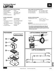
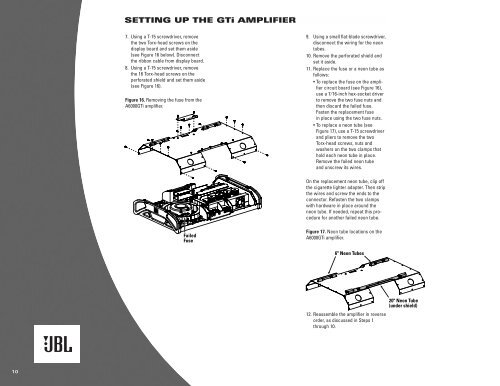
SETTING UP THE GTi AMPLIFIER<br />
7. Using a T-15 screwdriver, remove<br />
the two Torx-head screws on the<br />
display board and set them aside<br />
(see Figure 16 below). Disconnect<br />
the ribbon cable from display board.<br />
8. Using a T-15 screwdriver, remove<br />
the 16 Torx-head screws on the<br />
perforated shield and set them aside<br />
(see Figure 16).<br />
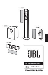
Figure 16. Removing the fuse from the<br />
A6000GTi amplifier.<br />
9. Using a small flat-blade screwdriver,<br />
disconnect the wiring for the neon<br />
tubes.<br />
10. Remove the perforated shield and<br />
set it aside.<br />
11. Replace the fuse or a neon tube as<br />
follows:<br />
• To replace the fuse on the amplifier<br />
circuit board (see Figure 16),<br />
use a 7⁄16-inch hex-socket driver<br />
to remove the two fuse nuts and<br />
then discard the failed fuse.<br />
Fasten the replacement fuse<br />
in place using the two fuse nuts.<br />
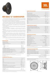
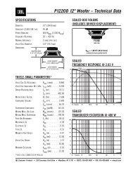
• To replace a neon tube (see<br />
Figure 17), use a T-15 screwdriver<br />
and pliers to remove the two<br />
Torx-head screws, nuts and<br />
washers on the two clamps that<br />
hold each neon tube in place.<br />
Remove the failed neon tube<br />
and unscrew its wires.<br />
On the replacement neon tube, clip off<br />
the cigarette lighter adapter. Then strip<br />
the wires and screw the ends to the<br />
connector. Refasten the two clamps<br />
with hardware in place around the<br />
neon tube. If needed, repeat this procedure<br />
for another failed neon tube.<br />
Failed<br />
Fuse<br />
Figure 17. Neon tube locations on the<br />
A6000GTi amplifier.<br />
6" Neon Tubes<br />
12. Reassemble the amplifier in reverse<br />
order, as discussed in Steps 1<br />
through 10.<br />
20" Neon Tube<br />
(under shield)<br />
10