
Create successful ePaper yourself
Turn your PDF publications into a flip-book with our unique Google optimized e-Paper software.
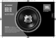
SETTING UP THE GTi AMPLIFIER<br />
REPLACING THE FUSE<br />
OR NEON TUBES<br />
The <strong>JBL</strong> A6000/A3000GTi amplifier<br />
is equipped with an internal fuse, a<br />
20-inch neon tube and two 6-inch neon<br />
tubes. Should the fuse or a neon tube<br />
fail, perform the following steps<br />
to replace the part:<br />
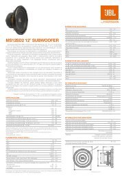
Figure 14. Removing bottom screws<br />
and the clear cover from the A6000GTi<br />
amplifier. NOTE: Do not remove the<br />
logo badge assembly.<br />
NOTE: For neon tube replacement, see<br />
your authorized <strong>JBL</strong> car audio dealer<br />
to purchase new StreetGlow ® neon<br />
tubes in 6- or 20-inch sizes.<br />
NOTE: Although the following<br />
steps discuss and illustrate how<br />
to disassemble a <strong>JBL</strong> A6000GTi,<br />
the disassembly procedure for a<br />
<strong>JBL</strong> A3000GTi is similar.<br />
1. Disconnect and unmount the<br />
amplifier from the vehicle. On a<br />
soft surface, turn the amplifier over<br />
to view the bottom. Using a T-25<br />
screwdriver, remove the four large<br />
Torx-head screws along the bottom<br />
edges and set them aside (see<br />
Figure 14).<br />
2. Turn the amplifier over to view the<br />
top. Using a 5 ⁄32-inch Allen wrench,<br />
remove the four cap screws on the<br />
clear cover and set them aside (see<br />
Figure 14).<br />
3. Slide the clear cover off and set it<br />
aside (see Figure 14).<br />
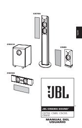
4. Using a T-15 screwdriver, remove<br />
the four Torx-head screws around<br />
the output panel and set them aside<br />
(see Figure 15).<br />
5. Repeat Step 4 for the input panel<br />
(see Figure 15).<br />
6. Remove the cover and set it aside<br />
(see Figure 15).<br />
Figure 15. Removing the input and<br />
output screws and the cover from the<br />
A6000GTi amplifier.<br />
9