

Skyjacker F565 Coil Spring Installation Instructions - Jegs
Skyjacker F565 Coil Spring Installation Instructions - Jegs
Skyjacker F565 Coil Spring Installation Instructions - Jegs

You also want an ePaper? Increase the reach of your titles
YUMPU automatically turns print PDFs into web optimized ePapers that Google loves.
Front <strong>Installation</strong>:<br />
1. Park the vehicle on level ground, set the emergency brake, and block the<br />
rear tires. Raise the vehicle and support frame rails using jack stands.<br />
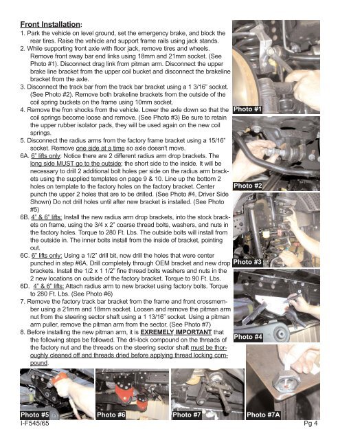
2. While supporting front axle with floor jack, remove tires and wheels.<br />
Remove front sway bar end links using 18mm and 21mm socket. (See<br />
Photo #1). Disconnect drag link from pitman arm. Disconnect the upper<br />
brake line bracket from the upper coil bucket and disconnect the brakeline<br />
bracket from the axle.<br />
3. Disconnect the track bar from the track bar bracket using a 1 3/16” socket.<br />
(See Photo #2). Remove both brakeline brackets from the outside of the<br />
coil spring buckets on the frame using 10mm socket.<br />
4. Remove the fron shocks from the vehicle. Lower the axle down so that the<br />
coil springs become loose and remove. (See Photo #3) Be sure to retain<br />
the upper rubber isolator pads, they will be used again on the new coil<br />
springs.<br />
5. Disconnect the radius arms from the factory frame bracket using a 15/16”<br />
socket. Remove one side at a time so axle doesn't move.<br />
6A. 6” lifts only: Notice there are 2 different radius arm drop brackets. The<br />
long side MUST go to the outside; the short side to the inside. It will be<br />
necessary to drill 2 additional bolt holes per side on the radius arm brackets<br />
using the supplied templates on page 9 & 10. Line up the bottom 2<br />
holes on template to the factory holes on the factory bracket. Center<br />
punch the upper 2 holes that are to be drilled. (See Photo #4, Driver Side<br />
Shown) Do not drill holes until after new bracket is installed. (See Photo<br />
#5)<br />
6B. 4” & 6” lifts: Install the new radius arm drop brackets, into the stock brackets<br />
on frame, using the 3/4 x 2” coarse thread bolts, washers, and nuts in<br />
the factory holes. Torque to 280 Ft. Lbs. The outside bolts will install from<br />
the outside in. The inner bolts install from the inside of bracket, pointing<br />
out.<br />
6C. 6” lifts only: Using a 1/2” drill bit, now drill the holes that were center<br />
punched in step #6A. Drill completely through OEM bracket and new drop<br />
brackets. Install the 1/2 x 1 1/2” fine thread bolts washers and nuts in the<br />
2 new locations on outside of the factory bracket. Torque to 90 Ft. Lbs.<br />
6D. 4” & 6” lifts: Attach radius arm to new bracket using factory bolts. Torque<br />
to 280 Ft. Lbs. (See Photo #6)<br />
7. Remove the factory track bar bracket from the frame and front crossmember<br />
using a 21mm and 18mm socket. Loosen and remove the pitman arm<br />
nut from the steering sector shaft using a 1 13/16” socket. Using a pitman<br />
arm puller, remove the pitman arm from the sector. (See Photo #7)<br />
8. Before installing the new pitman arm, it is EXREMELY IMPORTANT that<br />
the following steps be followed. The dri-lock compound on the threads of<br />
the factory nut and the threads on the steering sector shaft must be thoroughly<br />
cleaned off and threads dried before applying thread locking compound.<br />
Photo #1<br />
Photo #2<br />
Photo #3<br />
Photo #4<br />
Photo #5 Photo #6 Photo #7 Photo #7A<br />
I-F545/65 Pg 4


