

Skyjacker F565 Coil Spring Installation Instructions - Jegs
Skyjacker F565 Coil Spring Installation Instructions - Jegs
Skyjacker F565 Coil Spring Installation Instructions - Jegs

You also want an ePaper? Increase the reach of your titles
YUMPU automatically turns print PDFs into web optimized ePapers that Google loves.
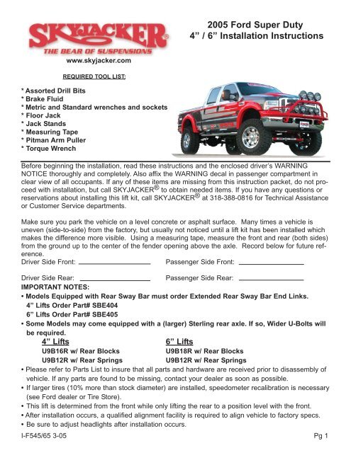
2005 Ford Super Duty<br />
4” / 6” <strong>Installation</strong> <strong>Instructions</strong><br />
www.skyjacker.com<br />
REQUIRED TOOL LIST:<br />
* Assorted Drill Bits<br />
* Brake Fluid<br />
* Metric and Standard wrenches and sockets<br />
* Floor Jack<br />
* Jack Stands<br />
* Measuring Tape<br />
* Pitman Arm Puller<br />
* Torque Wrench<br />
Before beginning the installation, read these instructions and the enclosed driver’s WARNING<br />
NOTICE thoroughly and completely. Also affix the WARNING decal in passenger compartment in<br />
clear view of all occupants. If any of these items are missing from this instruction packet, do not proceed<br />
with installation, but call SKYJACKER ® to obtain needed items. If you have any questions or<br />
reservations about installing this lift kit, call SKYJACKER ® at 318-388-0816 for Technical Assistance<br />
or Customer Service departments.<br />
Make sure you park the vehicle on a level concrete or asphalt surface. Many times a vehicle is<br />
uneven (side-to-side) from the factory, but usually not noticed until a lift kit has been installed which<br />
makes the difference more visible. Using a measuring tape, measure the front and rear (both sides)<br />
from the ground up to the center of the fender opening above the axle. Record below for future reference.<br />
Driver Side Front:<br />
Passenger Side Front:<br />
Driver Side Rear:<br />
Passenger Side Rear:<br />
IMPORTANT NOTES:<br />
• Models Equipped with Rear Sway Bar must order Extended Rear Sway Bar End Links.<br />
4” Lifts Order Part# SBE404<br />
6” Lifts Order Part# SBE405<br />
• Some Models may come equipped with a (larger) Sterling rear axle. If so, Wider U-Bolts will<br />
be required.<br />
4” Lifts 6” Lifts<br />
U9B16R w/ Rear Blocks<br />
U9B18R w/ Rear Blocks<br />
U9B12R w/ Rear <strong>Spring</strong>s<br />
U9B12R w/ Rear <strong>Spring</strong>s<br />
• Please refer to Parts List to insure that all parts and hardware are received prior to disassembly of<br />
vehicle. If any parts are found to be missing, contact your dealer as soon as possible.<br />
• If larger tires (10% more than stock diameter) are installed, speedometer recalibration is necessary<br />
(see Ford dealer or Tire Store).<br />
• This lift is determined from the front while only lifting the rear to a position level with the front.<br />
• After installation occurs, a qualified alignment facility is required to align vehicle to factory specs.<br />
• Be sure to adjust headlights after installation occurs.<br />
I-F545/65 3-05 Pg 1
Kit Box Breakdown:<br />
F5451:<br />
ITEM# DESCRIPTION QTY<br />
TB540-B TRACK BAR DROP BRACKET, 4" 1<br />
RAB545-S RADIUS ARM DROP BRKTS, 4" 2<br />
SBE5054-L EXTENDED SWAY BAR LINKS, 4" FRONT 2<br />
BSB25-B BUMP STOP BRACKETS, 2.5" TALL 2<br />
7154 STEERING STABILIZER, 4" 1<br />
CBL3401 CARRIER BEARING LOWERING KIT,4” 1<br />
FBL54 FRONT BRAKE LINE KIT,4" 1<br />
RB35 3.5" REAR BLOCK (NOT INCLUDED IN F5451S) 2<br />
58X312X16 U-BOLT WITH NUTS (58X312X1012 IN F5451S) 4<br />
HB-RABF545 HDWR BAG:RADIUS DROP BRKTS, 1<br />
HB-5250TBS HDWR BAG:TRK BAR,B-STOPS,SWAY BAR 1<br />
Hardware Bag Breakdown:<br />
HB-RABF545<br />
Radius Arm Drop Brackets<br />
ITEM# DESCRIPTION QTY<br />
34X2CTB 3/4 X 2 COARSE THREAD BOLT 8<br />
516X1FTB 5/16 X 1 FINE THREAD BOLT 2<br />
34CTN 3/4" COARSE THREAD LOCKNUT 8<br />
516FTN 5/16" FINE THREAD LOCKNUT 2<br />
34SAEW 3/4 SAE WASHER 16<br />
516SAEW 5/16 SAE WASHER 4<br />
ABS55-S ABS RELOCATION BRACKET 2<br />
HB-5250TBS<br />
Track Bar, Bump Stops, Sway Bar Links<br />
ITEM# DESCRIPTION QTY<br />
916X112FTB 9/16 X1 1/2 FINE THREAD BOLT 2<br />
916X3FTB 9/16 X 3 FINE THREAD BOLT 5<br />
38X112FTB 3/8 X 1 1/2 FINE THRD BOLT 2<br />
38X1FTB 3/8 X 1 FINE THREAD BOLT 2<br />
916FTN 9/16-18 NYLON INSERT LOCKNUT 7<br />
38FTN 3/8-24 FINE N/I LOCK NUT 4<br />
916SAEW 9/16 SAE WASHERS 10<br />
38X114FW 3/8 X 1 1/4 LARGE FENDER WASHER 2<br />
38SAEW 3/8 SAE WASHER 4<br />
D260PSS-S .938” LONG ANTI CRUSH SLEEVES 3<br />
142118 SWAY BAR END LINK SLEEVES 4<br />
SP2016 LARGE HOURGLASS BUSHINGS 4<br />
SBB250-B LOWER SWAY BAR BRACKETS 2<br />
916USSW 9/16" USS LARGE FLAT WASHER 4<br />
I-F545/65<br />
Pg 2
<strong>F565</strong>1:<br />
ITEM# DESCRIPTION QTY<br />
TB560-B TRACK BAR DROP BRACKET, 6" 1<br />
RAB565-L RADIUS DROP DOWN BRKT, DRIVER 6" 1<br />
RAB565-R RADIUS DROP DOWN BRKT, PASSENGER 6" 1<br />
SBE5056-L EXTENDED SWAY BAR LINKS, 6" FRONT 2<br />
BSB45-B BUMP STOP BRACKETS, 4.5" TALL 2<br />
7156 STEERING STABILIZER, 6" 1<br />
CBL255 CARRIER BEARING LOWERING KIT, 6” 1<br />
FBL56 FRONT BRAKE LINE KIT, 6" 1<br />
RB55 5.5" REAR BLOCK (NOT INCLUDED IN <strong>F565</strong>1S) 2<br />
58X312X18 U-BOLT WITH NUTS (58X312X1012 IN <strong>F565</strong>1S) 4<br />
HB-RAB<strong>F565</strong> HDWR BAG:RADIUS DROP BRKTS, 1<br />
HB-5250TBS HDWR BAG:TRK BAR,B-STOPS,SWAY BAR 1<br />
VH32 REAR VENT HOSE - 32" LONG 1<br />
Hardware Bag Breakdown:<br />
HB-RAB<strong>F565</strong><br />
Radius Arm Drop Brackets<br />
ITEM# DESCRIPTION QTY<br />
12x112FTB 1/2X 1 1/2 FINE THREAD BOLT 4<br />
12FTN 1/2" FINE THREAD LOCKNUT 4<br />
12SAEW 1/2 SAE WASHER 8<br />
34X2CTB 3/4 X 2 COARSE THREAD BOLT 8<br />
516X1FTB 5/16 X 1 FINE THREAD BOLT 3<br />
34CTN 3/4" COARSE THREAD LOCKNUT 8<br />
516FTN 5/16" FINE THREAD LOCKNUT 3<br />
RBLE5250 REAR BRAKE EXT BRACKET 6” 1<br />
34SAEW 3/4 SAE WASHER 16<br />
516SAEW 5/16 SAE WASHER 5<br />
38X114FW 3/8” LARGE FENDER WASHER 1<br />
ABS55-S ABS RELOCATION BRACKET 2<br />
HB-5250TBS<br />
Track Bar, Bump Stops, Sway Bar Links<br />
ITEM# DESCRIPTION QTY<br />
916X112FTB 9/16 X 1 1/2 FINE THREAD BOLT 2<br />
916X3FTB 9/16 X 3 FINE THREAD BOLT 5<br />
38X112FTB 3/8 X 1 1/2 FINE THRD BOLT 2<br />
38X1FTB 3/8 X 1 FINE THREAD BOLT 2<br />
916FTN 9/16-18 NYLON INSERT LOCKNUT 5<br />
38FTN 3/8-24 FINE N/I LOCK NUT 4<br />
916SAEW 9/16 SAE WASHERS 10<br />
38X114FW 3/8 X 1 1/4 LARGE FENDER WASHER 2<br />
38SAEW 3/8 SAE WASHER 4<br />
D260PSS-S TRACK BAR ANTI CRUSH SLEEVES 3<br />
142118 SWAY BAR END LINK SLEEVES 4<br />
SP2016 LARGE HOURGLASS BUSHINGS 4<br />
SBB5250-S LOWER SWAY BAR BRACKETS 2<br />
12USSW 1/2 USS LARGE FLAT WASHER 2<br />
916USSW 9/16" USS LARGE FLAT WASHER 4<br />
I-F545/65 Pg 3
Front <strong>Installation</strong>:<br />
1. Park the vehicle on level ground, set the emergency brake, and block the<br />
rear tires. Raise the vehicle and support frame rails using jack stands.<br />
2. While supporting front axle with floor jack, remove tires and wheels.<br />
Remove front sway bar end links using 18mm and 21mm socket. (See<br />
Photo #1). Disconnect drag link from pitman arm. Disconnect the upper<br />
brake line bracket from the upper coil bucket and disconnect the brakeline<br />
bracket from the axle.<br />
3. Disconnect the track bar from the track bar bracket using a 1 3/16” socket.<br />
(See Photo #2). Remove both brakeline brackets from the outside of the<br />
coil spring buckets on the frame using 10mm socket.<br />
4. Remove the fron shocks from the vehicle. Lower the axle down so that the<br />
coil springs become loose and remove. (See Photo #3) Be sure to retain<br />
the upper rubber isolator pads, they will be used again on the new coil<br />
springs.<br />
5. Disconnect the radius arms from the factory frame bracket using a 15/16”<br />
socket. Remove one side at a time so axle doesn't move.<br />
6A. 6” lifts only: Notice there are 2 different radius arm drop brackets. The<br />
long side MUST go to the outside; the short side to the inside. It will be<br />
necessary to drill 2 additional bolt holes per side on the radius arm brackets<br />
using the supplied templates on page 9 & 10. Line up the bottom 2<br />
holes on template to the factory holes on the factory bracket. Center<br />
punch the upper 2 holes that are to be drilled. (See Photo #4, Driver Side<br />
Shown) Do not drill holes until after new bracket is installed. (See Photo<br />
#5)<br />
6B. 4” & 6” lifts: Install the new radius arm drop brackets, into the stock brackets<br />
on frame, using the 3/4 x 2” coarse thread bolts, washers, and nuts in<br />
the factory holes. Torque to 280 Ft. Lbs. The outside bolts will install from<br />
the outside in. The inner bolts install from the inside of bracket, pointing<br />
out.<br />
6C. 6” lifts only: Using a 1/2” drill bit, now drill the holes that were center<br />
punched in step #6A. Drill completely through OEM bracket and new drop<br />
brackets. Install the 1/2 x 1 1/2” fine thread bolts washers and nuts in the<br />
2 new locations on outside of the factory bracket. Torque to 90 Ft. Lbs.<br />
6D. 4” & 6” lifts: Attach radius arm to new bracket using factory bolts. Torque<br />
to 280 Ft. Lbs. (See Photo #6)<br />
7. Remove the factory track bar bracket from the frame and front crossmember<br />
using a 21mm and 18mm socket. Loosen and remove the pitman arm<br />
nut from the steering sector shaft using a 1 13/16” socket. Using a pitman<br />
arm puller, remove the pitman arm from the sector. (See Photo #7)<br />
8. Before installing the new pitman arm, it is EXREMELY IMPORTANT that<br />
the following steps be followed. The dri-lock compound on the threads of<br />
the factory nut and the threads on the steering sector shaft must be thoroughly<br />
cleaned off and threads dried before applying thread locking compound.<br />
Photo #1<br />
Photo #2<br />
Photo #3<br />
Photo #4<br />
Photo #5 Photo #6 Photo #7 Photo #7A<br />
I-F545/65 Pg 4
Apply a heavy bead of the supplied thread locking compound all the<br />
way around the entire threads of the nut. (See Photo #7A). Once<br />
the thread locking compound has been applied, install the new pitman<br />
arm and factory nut. Torque factory nut to 350 Ft. Lbs.<br />
9. Locate the new track bar relocation bracket. First bolt the new bracket<br />
to the factory location on the cross member using the 9/16 X 3”<br />
fine thread bolts, washers and nuts. Be sure to use the (3) .938”<br />
long anti crush spacers between the front of the bracket and crossmember.<br />
Do not tighten at this time. (See Photo #8)<br />
10. Attach new track bar bracket to the frame using the (2) factory bolts.<br />
Torque all (5) track bar bracket bolts to 129 Ft. Lbs.<br />
11. Remove the factory bump stop and bump stop cup from the frame.<br />
The mounting location on the frame and the bump stop cup must be<br />
drilled out to 3/8”. (See Photo #9) Once drilled, the locator tab on<br />
top of the bump stop cup must be tapped flat so that the cup will sit<br />
flush against the bump stop relocation bracket. (See Photo #10)<br />
12. Locate the new bump stop relocation bracket. Attach the wide end<br />
of the new bracket to the factory position on the frame. Place a 3/8”<br />
small washer on the 3/8 x 1 1/2” bolt. Install bolt through top hole in<br />
bracket, and the frame and place the large 3/8” fender washer on<br />
top of the frame and secure with a 3/8” nut. Attach the factory bump<br />
stop cup to bottom of relocation bracket using the 3/8 x 1” fine<br />
thread bolt, 1 washer, and nut. (Do Not use washer under bolt head.<br />
Tighten all bolts. Reinsert OEM bump stop into OEM bump stop<br />
cup. (See Photo #11) Note: Photo #11 shows the bracket for a 6”<br />
lift. The bracket for a 4” lift will be shorter and not have any holes on<br />
the outside of bracket.<br />
13. Disconnect the ABS line from the factory radius arm using a 13mm<br />
wrench. Attach the new relocation bracket to the radius arm using<br />
the factory hardware. Attach the factory ABS bracket to the new<br />
extension bracket using the 5/16 x 1” fine thread bolts, washers,<br />
and nuts. (See Photo #12)<br />
14. Remove the front brakelines from the upper bracket. Next, simply<br />
pry the lower bracket open and remove brakeline from bracket.<br />
(See Photo #13). Disconnect the front brakeline from caliper.<br />
15. Attach the new driver side brakeline to the caliper. Note: Be very<br />
careful when attaching the brakeline to the caliper. The lower banjo<br />
fitting must be angled upward when attached. If not angled correctly,<br />
the brakeline will contact the body of the shock when turning.<br />
(Driver side brakeline shown in Photo #14) Attach the brakeline to<br />
the steering knuckle with the plastic cable clamps provided, using<br />
the stock bolt at the abs mounting position. (See Photo #14A)<br />
Photo #8<br />
Photo #9<br />
Photo #11<br />
Photo #10<br />
Photo #12 Photo #13<br />
Photo #14 Photo #14A<br />
I-F545/65 Pg 5
16A. Attach the drivers side brakeline bracket, with only one bend, to<br />
the driver side coil bucket using OEM bolt. Attach the factory hardline<br />
into the new stainless steel line through the hole in the new<br />
bracket. Secure new brakeline to the new bracket by inserting the<br />
brakeline clip through the groove in the new brakeline fitting (on top<br />
side of bracket). (See Photo #15) Please note that the passenger<br />
side brakeline bracket will look slightly different, but will attach the<br />
same way. (See Photo #16)<br />
16B. Now install the passenger side brakeline bracket using the brakeline<br />
bracket with 2 bends. Install bracket to coil bucket using OEM<br />
bolt. Install passenger side brakeline following steps #15 & #16A.<br />
17. Install the new coil springs. Be sure to reuse the factory rubber isolator<br />
pad on top. Let weight down on the new coils at this time. (See<br />
Photo #17) Bolt the stock track bar to the new track bar bracket<br />
using the factory hardware. Torque to 280 Ft. Lbs.<br />
18. The sway bar link lower mounts on the axle may need to be spread<br />
to allow for installation of the new lower sway bar link bracket. (See<br />
Photo #18)<br />
19. Assemble both of the new sway bar end links. Spray the large hourglass<br />
bushings with a lubricant and install into the eyes of the sway<br />
bar end links. Insert the steel sleeves into each bushing. Place the<br />
9/16 x 1 1/2” fine thread bolt through the new lower sway bar link<br />
bracket. (Do Not attach bracket to axle at this time.) Attach the bottom<br />
eye of the sway bar link to the new lower bracket using the 9/16<br />
x 3” fine thread bolt, washers, and nut. Torque to 129 Ft. Lbs.<br />
20. Attach this assembly to the axle housing mount by inserting the<br />
9/16 x 1 1/2” bolt through hole in factory sway bar mount on axle.<br />
Install a 9/16 Large USS washer and nut. Torque to 280 Ft. Lbs.<br />
(See Photo #19)<br />
21. Attach the upper eye of the sway bar links to the sway bar using the<br />
factory hardware while being sure to place the large 9/16” Large<br />
USS washer between the head of the bolt and the sway bar end link<br />
bushing. (See Photo #21)<br />
22. Reinstall the lower factory brakeline bracket to the axle. Place the<br />
new brakeline through the lower factory bracket and shift most of<br />
the slack up, away from caliper, and recrimp the ends to hold brake<br />
line in the bracket. (See Photo #20 and #21).<br />
Photo #15<br />
Photo #16<br />
Photo #17<br />
Photo #18<br />
Photo #19 Photo #20 Photo #21<br />
I-F545/65 Pg 6
22A. Attach factory drag link to new pitman arm and tighten. With drag<br />
link installed, check to assure there is adequate clearance between<br />
drag link tie rod and the track bar bolt head at full left turn. If there<br />
is any contact, we recommend for the track bar bolt to be replaced<br />
with a 20mm x 90mm(3.5") bolt grade 10.9(grade 8), and use a 3/4"<br />
SAE Flat washer between the bolt head and bracket. This will provide<br />
some additional clearance if needed. (See Photo #21A)<br />
23. Remove the factory steering stabilizer. Remove the factory bracket<br />
from the crossmember using 18mm socket. (See Photo # 22)<br />
24. Attach the new steering stabilizer bracket to the crossmember in the<br />
factory mounting holes using the factory hardware. Install the bolts<br />
from the front. Torque to 90 Ft. Lbs.<br />
24A. 6” lifts only: Install the 1/2 x 1 1/4” fine thread bolt, washers, and<br />
nut in the 3rd mounting hole. Torque to 90 Ft. Lbs. (See Arrow in<br />
Photo #23)<br />
25. Install the new tapered sleeve into the factory tapered mounting<br />
hole on the drag link. With the tapered sleeve installed, insert the<br />
new tapered stud. (See Photo #24)<br />
26. Install the new non-tapered stud into top of the new steering stabilizer<br />
bracket. Install the 5/8 hourglass bushings and boot onto the<br />
new steering stabilizer. Install the new steering stabilizer on new<br />
studs and tighten all nuts. (See Photo #25)<br />
Rear <strong>Installation</strong>:<br />
27. Raise rear and support securely with jack stands and block the front<br />
wheels. Remove the tires, shocks, & U-bolts. Remove vent hose<br />
from frame. (CAUTION: the rear axle will now be free to move, so<br />
support securely on floor jack.)<br />
28. New rear leaf spring installation: Unbolt and remove the stock<br />
rear springs, then install the new rear springs with long end of<br />
spring towards rear bumper. (NOTE: be sure thick end of bottom<br />
degree shim is also towards rear bumper.) The factory blocks are<br />
maintained. Go to Step #30.<br />
29. Rear block installation: Install the new lift blocks, taller end toward<br />
the rear bumper, between springs and original blocks (new block<br />
will be installed on top of the original block).<br />
30. Using the floor jack, raise axle up to rear springs. Be sure the<br />
spring tie bolts and block pins all align in proper holes and are completely<br />
seated. Install and torque new u-bolts to 110 ft. lbs.<br />
31A. 4” lifts only: Reattach vent hose, but relocate hose to the bottom<br />
of frame rail.<br />
31B. 6” lifts only: Replace original vent hose with new longer vent hose<br />
provided. Reattach vent hose, but relocate hose to the bottom of<br />
frame rail.<br />
32. Install new shocks and tires, then lower vehicle to ground. (See<br />
Photo #26)<br />
Photo #21A<br />
Photo #22<br />
Photo #23<br />
Photo #24<br />
Photo #25<br />
Photo #26<br />
I-F545/65 Pg 7
33. 6” lifts only: Remove the top of the brakeline from the OEM bracket.<br />
Attach new relocation bracket to hole in original brakeline bracket.<br />
Place small 5/16” washer on 5/16 x 1” bolt first. Insert bolt through<br />
new relocation bracket, then through factory upper bracket. Now<br />
place the large 3/8” Fender washer onto bolt and tighten with 5/16”<br />
nut. Reconnect OEM brakeline through hole in new relocation bracket<br />
using original clip. (See Photo #27)<br />
34. 4 & 6” lifts: BLEEDING THE BRAKE SYSTEM:<br />
Photo #27<br />
A) Fill master cylinder with D.O.T. approved brake fluid.<br />
B) Pump the brake pedal and hold down. While the pedal is down, open the bleeder nut to release air<br />
out of the system. Close or tighten nut, then let pedal up and re-pump. Continue the pumping/bleeding<br />
process until fluid is being excreted out of the bleeder nut and/or until no air is being expelled.<br />
C) Bleed each line (6” bleed front & rear; 4” bleed front). Make sure your master cylinder is full of brake<br />
fluid after each bleeding process.<br />
D) The brake pedal will not "pump up" or have excessive down-travel if all the air is out of the system.<br />
F) It is the customer's responsibility to check brake line for any leaks, abrasion, proper clearances, and<br />
brake line fittings after the first 100 miles and after every off-road activity.<br />
FINAL NOTES:<br />
• After installation is complete, double check that all nuts and bolts are tight. (Do not retighten nuts and<br />
bolts where Thread Lock Compound was used.)<br />
• If new tires are installed that are more than 10% taller than original tires, the speedometer must be<br />
recalibrated for the rear wheel anti-lock brake system to function properly. Contact an authorized Ford<br />
dealer for details on recalibration.<br />
• With the vehicle on the floor, cycle steering full left & right turns. Inspect steering, suspension and driveline<br />
systems for proper operation, tightness and adequate clearance. Recheck brake hose/fittings for<br />
leaks. Be sure to check clearance between the front brakeline at the caliper and the shock.<br />
• Have headlights readjusted to proper settings.<br />
• Have a qualified alignment center realign front end to factory specifications.<br />
• Re-torque all bolts after the first 100 miles. (Do not retighten nuts where Thread Lock Compound was<br />
used.)<br />
Seat Belts Save Lives, Please Wear Your Seat Belt.<br />
Note: On models equipped with a carrier bearing on the rear driveshaft, it will be necessary to install<br />
the supplied carrier bearing lowering bracket to help eliminate any driveline vibration. Install using<br />
the supplied 7/16” bolts and washers. Bracket will mount between the carrier bearing and the factory<br />
mount on the frame.<br />
I-F545/65<br />
Pg 8
Radius Arm Template - 6” Lift Only<br />
Driver’s Side<br />
I-F545/65<br />
Pg 9
Pg 10
Radius Arm Template - 6” Lift Only<br />
Passenger Side<br />
I-F545/65<br />
Pg 11
Pg 12
Important Note:<br />
After installation is completed and vehicle is on the ground with weight on the springs. Clearance<br />
must be checked between the driver side rear shock. In some situations, under acceration, the<br />
shock will contact the u-bolt that attaches the lower bracket to the axle. (See Photo #1)<br />
Loosen the u-bolt that attaches the bracket to the axle. Rotate the shock bracket upwards so that<br />
more additional clearance is achieved between the shock body and the u-bolt. (See Photo #2)<br />
Once in desired position, retighten the U-Bolt and torque to 90 ft. lbs. It is now recommended to<br />
tack weld the bracket to the axle tube to prevent movement of the bracket.<br />
Photo #1 Photo #2<br />
Pg 13
Register your <strong>Skyjacker</strong> ® 2005 Ford Super Duty<br />
product and receive a FREE Softride ® <strong>Coil</strong> <strong>Spring</strong> Pen.<br />
Also in celebration of <strong>Skyjacker</strong>’s 30 th Anniversary every 30 th entry receives a FREE<br />
<strong>Skyjacker</strong> ® T-Shirt! Please select Shirt size below, in the event your entry is a WINNER!<br />
Name: _______________________________________________________ Today’s Date: __________________<br />
Street Address: ________________________________________________________________________________<br />
City: __________________________________________ State: _____________________<br />
Day Time Phone: ________ - ________ - ___________<br />
Zip: ______________<br />
E-Mail: ____________________________________<br />
<strong>Skyjacker</strong> ® Product Purchased from: _________________________________________________________<br />
Order will not be processed without a copy of your invoice.<br />
Engine Size: 5.4L / V-8 6.8L / V-10 6.0L / Diesel<br />
Transmission: Manual Automatic Drive: 4x4 4x2<br />
Cab Type: Regular Cab Super Cab Crew Cab Box / Bed Size: 6'3/4" 8'<br />
Shirt Size: Small Medium Large X-Large XX-Large XXX-Large<br />
<strong>Skyjacker</strong> ® occasionally uses customers vehicles in print ads, catalogs and on the web. If you are interested in<br />
showing off your 2005 Ford Super Duty, let us know. You can submit your action photos to <strong>Skyjacker</strong> ® via<br />
“Real Rides” at skyjacker.com or email high res images to info@skyjacker.com<br />
Please allow 6 - 8 weeks for delivery. Your pen will be shipped directly to the address provided at No Charge.<br />
Pg 14


