
You also want an ePaper? Increase the reach of your titles
YUMPU automatically turns print PDFs into web optimized ePapers that Google loves.
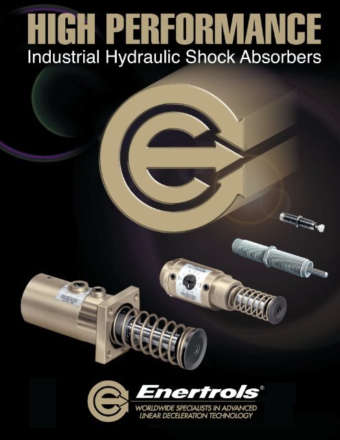
Industrial Hydraulic <strong>Shock</strong> <strong>Absorbers</strong><br />
Any mechanism that moves and that must be stopped is a potential application for controlled linear<br />
deceleration. There is no more effective way to achieve that control than through the use of Enertrols<br />
shock absorbers. With them, you can quickly and safely stop any type of motion, including:<br />
Straight-line, rotary, free-falling, sliding, rolling, etc. It makes no difference if the motion is driven<br />
electrically, mechanically, hydraulically, or pneumatically. Listed below are a few areas where<br />
Enertrols shock absorbers have replaced solid stops, deceleration valves, flow control valves,<br />
cylinder cushions, springs, rubber bumpers, dash-pots, feed controls, hydraulic checks, complicated<br />
and costly circuits and conventional industrial shock absorbers.<br />
■ AUTOMOTIVE:<br />
Press welders, Extractors, Blank<br />
loaders, Transfer shuttles, Roll overs,<br />
Pivoting pillars, K.D. Fixtures, Drop-away<br />
clamps, End stops, Overhead cranes,<br />
Destackers, Iron hands, Conveyors, Lift<br />
and carry units, Walking beams, Welding<br />
guns, Flying shears, Press weld trans.<br />
and many, many more.<br />
■ FOUNDRY:<br />
Core machines, Flask stops, Pattern<br />
shuttles, Rammer carriage stops, Roll<br />
overs, Cope & drag pick off, Overhead<br />
cranes, Turntables, Cooling lines,<br />
Disappearing stops, Cope & drag<br />
punch out, Cope mold closer, Drag<br />
mold set on, Drag mold lift off,<br />
Sand shields, Push off cylinder,<br />
Elevator stop, Conveyor stop<br />
■ STEEL:<br />
Up-enders, Down-enders, Strip<br />
support arms, Coil buggies,<br />
Ingot buggies, Transfer cars,<br />
Bloom stops, Entry<br />
table stops, Fly shears,<br />
Manipulators, Run-out<br />
tables, C-car at coilers,<br />
Overhead cranes,<br />
Banding & Strapping,<br />
Bar turners, Furnace<br />
stops, Tube stops,<br />
Draw benches<br />
Gold Line<br />
Fixed Flange<br />
<strong>Shock</strong> <strong>Absorbers</strong><br />
<strong>Standard</strong> Adjustable<br />
SA 1/4" x 1/2"<br />
<strong>Shock</strong> Absorber<br />
■ RUBBER:<br />
Tire curing press – Loading arm, Post<br />
tire inflator, Vertical load head; Tire<br />
Building Machine – Bead set, Collapsing<br />
drum, Servicer tray; Bias cutter,<br />
Guillotine cutter, Skivers, Tread cutter,<br />
Force Variation machine, Wig-Wag,<br />
Conveyors, Calendars<br />
■ LUMBER/PAPER/TEXTILE/OTHER:<br />
Roll stops, Weighing stations, Saw<br />
cut-off, Drop chutes, Vernier calipers,<br />
Saw carriages, Log turners, Stops,<br />
Picker arms, Loom shuttles, Fabric<br />
rolls, Carpet presses, Injection molding<br />
doors, Die-cast machine transfers,<br />
Pick-off arms<br />
■ PACKAGING:<br />
Drop packer, Tunnel packer, Traffic cop,<br />
Index stations, Turn tables, Conveyor<br />
stops, Filling, Palletizers, Bagging<br />
SILVERLINE SASL<br />
Primary Mount<br />
<strong>Shock</strong> Absorber with<br />
Rear Flange<br />
USED BY ALMOST EVERY INDUSTRY TO INCREASE PROFITABILITY<br />
3
4<br />
ENERTROLS CATALOG GL05<br />
<strong>Shock</strong> <strong>Absorbers</strong> – Where are They Used? 3<br />
Introduction to Hydraulic <strong>Shock</strong> <strong>Absorbers</strong> 5<br />
Enertrols – An Overview 6-9<br />
<strong>Standard</strong> Enertrols <strong>Shock</strong> <strong>Absorbers</strong> 10-11<br />
<strong>Standard</strong> Enertrols <strong>Shock</strong> <strong>Absorbers</strong> for Special Applications 12-13<br />
Accessories & Special <strong>Shock</strong> <strong>Absorbers</strong> 14-15<br />
Selecting the Correct TYPE <strong>Shock</strong> Absorber 16<br />
Selecting the Correct MODEL <strong>Shock</strong> Absorber 17<br />
Selecting the Correct SIZE <strong>Shock</strong> Absorber 18-23<br />
Energy Capacity Ratings – for All <strong>Standard</strong> Models 24-26<br />
Drawings, Dimensions & How-to-Order - Series 9M, 10E, 10M, 25&75<br />
Sub-Miniature Non-Adjustable Full Threaded-Body <strong>Shock</strong> <strong>Absorbers</strong> 27<br />
Drawings & Dimensions – Series 150, 225, 450, 600, 1 /2 x 1 & 1 /2 x 2<br />
Miniature Non-Adjustable Full Threaded-Body <strong>Shock</strong> <strong>Absorbers</strong> 28<br />
Drawings & Dimensions – Series 30, 35, 1 /4, 3 /8 and 1 /2 Bore<br />
Miniature Adjustable Full Threaded-Body <strong>Shock</strong> <strong>Absorbers</strong> 29<br />
Accessories for Sub-Miniature & Miniature Adjustable & Non-Adjustable<br />
Full Threaded-Body <strong>Shock</strong> <strong>Absorbers</strong> 30<br />
How-to-Order Miniature Full Threaded-Body <strong>Shock</strong> <strong>Absorbers</strong> 31<br />
Drawings & Dimensions – Mid-Size Non-Adjustable<br />
Threaded-Body Series <strong>Shock</strong> <strong>Absorbers</strong> 32<br />
How-to-Order Mid-Size Non-Adjustable Threaded-Body <strong>Shock</strong> <strong>Absorbers</strong> 33<br />
Drawings & Dimensions – 1 /2, 3 /4 & 1 1 /8 Bore<br />
Gold-Line Primary Mount <strong>Shock</strong> <strong>Absorbers</strong> 34<br />
How-to-Order Gold Line Primary Mount <strong>Shock</strong> <strong>Absorbers</strong> 35<br />
Drawings & Dimensions – Mounting Stop Collars, Positive Stop Collars,<br />
Retention Kits, Mounting Plates & Brackets, Typical Installations 36-39<br />
Drawings & Dimensions – 3 /4, 1 1 /8, 1 1 /2, 2, 2 1 /4 & 3 Bore<br />
Gold Line Fixed Flange <strong>Shock</strong> <strong>Absorbers</strong> 40-41<br />
Drawings & Dimensions – 4 Bore Primary Mount and Lug Mount <strong>Shock</strong> <strong>Absorbers</strong> 42<br />
How-to-Order Gold Line Fixed Flange <strong>Shock</strong> <strong>Absorbers</strong> 43<br />
Drawings & Dimensions – 3 /4, 1 1 /8, 1 1 /2, & 2 1 /4 Bore<br />
SILVERLINE Low-Velocity <strong>Shock</strong> <strong>Absorbers</strong> 44<br />
How-to-Order SILVERLINE Low-Velocity <strong>Shock</strong> <strong>Absorbers</strong> 45<br />
Drawings & Dimensions – 19 & 28mm Bore Mounting<br />
High Precision Metric (HPM) Fixed Flange <strong>Shock</strong> <strong>Absorbers</strong> 46<br />
Drawings and Dimensions - Air/Oil Tanks 47<br />
Installation Information & Tips 37, 48-49<br />
Construction & Parts Descriptions 50<br />
Computer Sizing Software, CAD Drawings & Website (www.enertrols.com) 51<br />
Enertrols • 38284 Abruzzi Dr., Westland, MI 48185 • Tel: 734.595.4500 • Fax: 734.595.6410 • www.enertrols.com<br />
Copyright Enertrols. 2005
INDUSTRIAL HYDRAULIC SHOCK ABSORBERS<br />
The Most<br />
Effective Way<br />
to STOP a<br />
Moving Object!<br />
By eliminating the damage-causing impact forces created by moving loads and objects<br />
through controlled linear deceleration, Enertrols shock absorbers let you:<br />
■ Increase operating speeds<br />
■ Increase operating loads<br />
■ Increase system performance<br />
■ Increase reliability<br />
■ Reduce stress in equipment<br />
■ Reduce design & fabrication costs<br />
■ Reduce noise levels<br />
■ INCREASE PROFITS!<br />
For years, industry was faced with the problem of<br />
stopping moving objects used in manufacturing without<br />
destroying them, or the stopping device. Everything<br />
that moves possesses kinetic energy that must be dissipated to stop movement. The heavier the object, and/or the<br />
faster it moves, the higher the kinetic energy becomes. Impact forces due to stopping become extremely high and<br />
damaging unless properly controlled.<br />
As today’s sophisticated automated machines evolved they have demanded higher operating speeds and shorter<br />
stopping times, greatly multiplying the build-up of kinetic energy and the problem of controlling it.<br />
Some commonly used stopping devices such as springs, rubber bumpers and dashpots, add to shock loading rather<br />
than reducing it. They do not dissipate energy at a uniform rate. The moving object is subjected to high shock loading<br />
at either the end, or the beginning, of the deceleration stroke.<br />
When stopping a moving weight or load, hydraulic shock absorbers convert kinetic energy to thermal energy (heat).<br />
The optimum operating condition occurs when this energy is dissipated at a nearly constant rate as the load is<br />
decelerated to zero velocity in the least distance in the least amount of time with no abrupt force peaks throughout<br />
the stroke. We call it controlled linear deceleration.<br />
By installing Enertrols industrial hydraulic shock absorbers, you can reduce damaging impact forces significantly<br />
enough to permit higher speeds and production rates, thereby increasing your profits. Of all existing deceleration<br />
methods, Enertrols shock absorbers are quite simply the best and most cost-effective means to stop a moving object.<br />
5
Enertrols… an Overview<br />
E<br />
nertrols was founded in 1973 to design and manufacture high-performance industrial hydraulic shock absorbers.<br />
Recognizing the need for a shock absorber with the ability to withstand the high cycle rates of modern automated<br />
manufacturing lines, we designed and built our first shocks to do just that. These high-quality shocks were sturdy<br />
enough to operate over a long period of time under all kinds of adverse conditions with little, or no, maintenance.<br />
As a result, Enertrols (our name combines Energy and Controls) has grown from a small local manufacturer to a position<br />
as a leading international supplier of deceleration devices to all major industries.<br />
The introduction of our Gold Line Series gave industry a proven source of reliable and rugged high-performance shock<br />
absorbers. Enertrols began setting the pace with an industry “first” with its debut of the high-capacity Gold Line Series in 1983.<br />
A year later, we introduced the first Prox <strong>Shock</strong>, which featured an on-board proximity sensor.<br />
Mounting Stop Collars (MSC) and Positive Stop Collars (PSC) for Gold Line shocks were added in 1986. They were followed<br />
in 1988 by our unique SILVERLINE Series, industry’s first low-velocity shock absorber, capable of working efficiently in slowmoving,<br />
high effective weight conditions. Enertrols large 4" Bore Series and a line of <strong>Standard</strong> Mounting Plates & Brackets for<br />
Primary Mount Series shock absorbers, were new items in 1989.<br />
To kick off the ’90s, Enertrols introduced a new series of miniature, full threaded-body, adjustable shock absorbers. Double-acting<br />
Dampers and other special-purpose shock absorbers were also new in 1990. That same year saw us introduce a milestone in our<br />
industry; the first Five-Year Warranty on industrial hydraulic shock absorbers, covering our Gold Line and SILVERLINE Series.<br />
1993 saw the addition of a line of non-adjustable, miniature, “self-compensating” shock absorbers, featuring full threaded-body<br />
design in seven different models. Several new full threaded-body adjustable shocks were introduced in 1997. The non-adjustable<br />
miniature line was expanded to 15 models in 1998.<br />
The 90’s closed with the introduction of our new High-Precision Metric Series (HPM) of Fixed Flange <strong>Shock</strong> <strong>Absorbers</strong>. These<br />
“metric mounting” models provide positive set-down positioning repeatable within ± .05mm plus easy “bolt-in-place” installation.<br />
Year 2000 brought PSS Positive Stop Systems for Gold Line and SILVERLINE Primary Model <strong>Shock</strong> <strong>Absorbers</strong>.<br />
Enertrols Armor Line Miniature Full Threaded-Body <strong>Shock</strong> <strong>Absorbers</strong> kicked off 2002. Featuring 10 different sizes and<br />
38 adjustable and non-adjustable models, they provide effective weight capacities from 2 to 6,000 lbs. This line is coated with<br />
a thin, dense, chrome-plating that nodularly adheres to every surface of the high-strength steel body. Use them in a corrosive<br />
environment. We announced our line of mid-size threaded-body shocks (32 models) in 2003.<br />
A new line of Sub-Miniature Full Threaded-Body <strong>Shock</strong> <strong>Absorbers</strong>, plus additional Miniature Series Models, will be available<br />
beginning in 2005.<br />
All Enertrols products are available in a wide range of models and sizes … at very competitive prices with on-time delivery …<br />
world-wide. We back that up with experienced sales, engineering, manufacturing and service personnel … world-wide.<br />
ISO 9001: 2000<br />
CERTIFIED<br />
ISO 9001: 2000 Certification<br />
As export-minded manufacturers, Enertrols recognizes the need to agree on world standards to aid the<br />
international trading process. Since Enertrols is committed to supplying world-class industrial shock<br />
absorbers, we are striving to continuously improve not only the quality of our products, but every step in the<br />
concept, design, build, test and final installation in the customers plant. Quality is our benchmark at all times;<br />
with 100% follow-through by all employees. ISO 9001: 2000 Certification ratifies our commitment!<br />
EXCLUSIVE Five-Year WARRANTY<br />
Enertrols guarantees all of its Gold Line and SILVERLINE adjustable hydraulic shock absorbers to be free of defects in both<br />
materials and manufacturing workmanship for a period of five full years from date of purchase. With the exception of “soft seals,”<br />
these products are guaranteed not to fail during the warranty period from premature wear when properly sized and installed.<br />
Foundry installations, or other high-contaminant applications, are limited to a two-year warranty period. For complete details,<br />
contact your Enertrols distributor, or the factory.<br />
6
Controlled Linear Deceleration<br />
The most effective way to stop a moving object<br />
To achieve controlled linear deceleration, the pressure on the<br />
piston area must remain as constant as possible throughout the<br />
deceleration stroke. Enertrols adjustable hydraulic shock absorbers<br />
meter oil through a computer-calculated series of exponentially<br />
spaced orifices in a high-pressure inner tube as the piston rod<br />
moves through its stroke (see cut-away photo). The crosssectional<br />
area of all the orifices is selected by rotating an adjustor.<br />
As the piston moves through its stroke, its velocity is decreasing,<br />
STROKE<br />
requiring changes in orifice area to maintain constant pressure.<br />
CONTROLLED LINEAR DECELERATION<br />
This is achieved as the piston closes off each orifice as it travels<br />
down the bore to end of stroke. Oil displaced by the piston rod makes room for itself by compressing a closed-cell,<br />
sponge-like material in self-contained, internal accumulator models. Displaced oil may also be<br />
routed to an external accumulator for cooling if high cycle rates cause excessively<br />
high temperatures.<br />
Cut-away of Gold Line<br />
Primary Mount 3/4" Bore<br />
Model with 2" Stroke<br />
Illustrates the Heavy-Duty<br />
Construction common to all<br />
Enertrols <strong>Shock</strong> <strong>Absorbers</strong><br />
Dashpots, snubbers and cylinder cushions have only a single,<br />
fixed-area orifice, which is why they cannot dissipate energy<br />
at a uniform rate. More efficient Enertrols Gold Line<br />
adjustable shock absorbers deliver true linear deceleration<br />
over a broad range of speed and weight<br />
combinations, compensating for changes in both weight<br />
and velocity. They are easily fine-tuned to obtain<br />
maximum cycle rates with soft, non-destructive stops<br />
every time.<br />
The Enertrols Product Line<br />
Enertrols has a complete product line with over 100 standard shock absorber models with capacities<br />
from 25 to over 1 1 /2 million inch-pounds per cycle. Most models can be equipped with<br />
internal accumulators as self-contained units, or equipped with external accumulators<br />
and air/oil tanks for maximum heat capacity. They are available in both adjustable<br />
and non-adjustable types in all of the basic standard mounting styles.<br />
In addition, we offer industry a choice of primary or welded fixed-flange<br />
mounting models in most bore and stroke sizes. Special application<br />
models, such as our PROX SHOCK line<br />
equipped with position-sensing electronic<br />
proximity switches, the QCM (Quick-<br />
Change Mount) Models, <strong>Standard</strong><br />
Long-Stroke Models and designedto-order<br />
specials are also available.<br />
FORCE<br />
Gold Line Fixed-Flange<br />
Mounting Series 3/4" Bore<br />
Adjustable <strong>Shock</strong> <strong>Absorbers</strong><br />
Gold Line Primary<br />
Series 3/4" Bore<br />
Adjustable <strong>Shock</strong><br />
<strong>Absorbers</strong><br />
Armor Line Non-Adjustable<br />
Miniature Self-Compensating<br />
<strong>Shock</strong> Absorber<br />
7
ISO 9001: 2000<br />
CERTIFIED<br />
Quality Assurance<br />
Every component produced for Enertrols products receives inspection coverage to<br />
assure conformance with all the requirements, specifications and drawings of our<br />
products. Both management and manufacturing, as well as all other personnel,<br />
are in complete agreement that the reliability requirements of our shock absorbers<br />
preclude any compromise in the quality of any component part. Enertrols was<br />
awarded ISO 9001: 2000 Certification in 2002.<br />
Enertrols engineering department controls all product drawings and specifications with a<br />
system that assures the latest information will be available to, and at the time and place of,<br />
inspection. Final inspection is performed on all manufactured parts and processes in<br />
accordance with applicable purchase orders, work orders, drawings and specifications.<br />
A sampling plan that is in accordance with mil spec MIL-105-D is used by inspectors whenever<br />
feasible to assure the acceptance of quality parts only. All completed assemblies and shock absorbers are inspected for quality<br />
and performance prior to shipment. Approved units are then properly packaged to prevent damage during transit.<br />
Why Enertrols?<br />
We firmly believe that all of the products we manufacture and ship are of the highest quality, assuring our customers the utmost in<br />
reliability and production uptime. There are five major reasons why Enertrols is your best value on the industrial shock<br />
absorber market today:<br />
1-1/2" Bore Gold<br />
Line Fixed Front<br />
Flange <strong>Shock</strong><br />
Absorber<br />
■ HEAVY-DUTY DESIGN. Enertrols shock absorbers deliver more inch-lbs of capacity<br />
per cycle. This often permits you to downsize to a smaller size shock absorber than would<br />
be possible with a competitive brand.<br />
■ PRICE AND DELIVERY. Enertrols has the best in the industry.<br />
We normally ship from our large inventories to stocking<br />
distributors in all major market areas.<br />
■ TECHNICAL SUPPORT. Enertrols has a complete<br />
technical support group available to engineering<br />
departments and build sources. It will follow your<br />
project, from concept through production, with<br />
computer-aided application engineering design assistance. Other specialists<br />
are available to assist in installation, trouble-shooting and the answering of<br />
any questions that may arise.<br />
■ POSITIVE & MOUNTING STOP COLLARS. Enertrols was the<br />
first to furnish industry with these time and money savers. They<br />
provide precise work-positioning, as an integral part of the shock<br />
absorber, while eliminating costly external stops. Their use can mean<br />
substantial savings on any applicable mounting installation.<br />
■ FIVE-YEAR WARRANTY. Enertrols Limited<br />
Warranty guarantees all Gold Line and SILVERLINE<br />
shock absorbers to be free from defects in materials<br />
and manufacturing workmanship for five (5) years<br />
(with the exception of “soft seals”).<br />
SILVERLINE SASL,<br />
Primary Mount<br />
<strong>Shock</strong> Absorber<br />
with Rear Flange<br />
19mm Bore High<br />
Precision Metric<br />
(HPM) <strong>Shock</strong><br />
with Positive<br />
Stop Collar<br />
3/4" Bore Gold<br />
Line Fixed Flange<br />
<strong>Shock</strong> Absorber<br />
3/4" Bore Gold Line<br />
Primary <strong>Shock</strong><br />
Absorber with<br />
Soft Pad option<br />
8
Construction & Design Features<br />
MINIATURE ADJUSTABLE & NON-ADJUSTABLE (SHOWN)<br />
FULL THREADED-BODY MODELS<br />
Hardened steel metering tube has metering<br />
holes with knife edges for high flow efficiency<br />
Versatile full threaded-body can<br />
be mounted in any position using<br />
furnished jam nut. Screw-on<br />
threaded flanges also available.<br />
Heavy-duty, high-cycle<br />
return spring<br />
Floating, heat-treated piston head with<br />
built-in check valve controls flow of oil<br />
as shock absorber operates<br />
Return oil<br />
flow passages<br />
Precision machined surfaces<br />
for close-tolerance fits<br />
Available with American<br />
& metric threads<br />
Closed-cell accumulator sponge is compressed<br />
by oil forced through metering holes. It<br />
expands to help force oil back into bore as<br />
spring returns piston to its original position<br />
Extra-long rod bearing for maximum<br />
life and side load capacity<br />
Rod seal and wiper assembly<br />
Built-in Positive Stop for work<br />
positioning. Protects shock from<br />
bottoming out at end of stroke.<br />
Hardened and ground steel piston rod for<br />
maximum strength. Chrome plated for excellent<br />
corrosion and wear resistance.<br />
STANDARD PRIMARY MOUNT & FIXED FLANGE MODELS<br />
Adjustor turns through a full 360 degrees, from ‘Hard’ to ‘Soft’ and back to ‘Hard’ in<br />
one revolution. More precise adjustment than competitive limited-range designs<br />
Precision machined shoulders provide exact positioning. This<br />
permits rotation of the body for easy access to the side-located<br />
adjustor, without changing set-down dimension of the installation<br />
Extra-large diameter, solid one-piece piston and<br />
rod for maximum strength. Rod is heat treated,<br />
ground and chrome-plated for excellent<br />
corrosion and wear resistance<br />
Versatile Primary-Mount Series can be<br />
front or rear mounted, using threads at<br />
either end of the heavy-duty steel body<br />
Cast iron high-pressure<br />
piston ring seal<br />
Easily disassembled for<br />
fast field repairs. All<br />
component parts and<br />
seals are readily available<br />
Corrosion-resistant<br />
return springs standard<br />
<strong>Standard</strong> or Viton<br />
seals available<br />
Hardened button standard<br />
on all models. Soft pads<br />
for quiet-mar-free<br />
operation are available<br />
Closed-cell<br />
accumulator sponge<br />
Wrench flats on body<br />
for easy installation<br />
Plated zinc-chromate finish for<br />
good appearance and superior<br />
corrosion resistance<br />
Extra-long rod bearings<br />
for maximum life and<br />
side load capacity<br />
Hardened ball-type<br />
check valve for<br />
positive sealing<br />
Precision-machined surfaces and<br />
extremely close tolerance fits<br />
Strong, heat-treated steel, high-pressure internal metering tubes have<br />
knife-edge orifices for high flow efficiency. ENERTROLS patented metering<br />
system requires NO readjustment when fluid temperatures change<br />
9
<strong>Standard</strong> <strong>Shock</strong> <strong>Absorbers</strong><br />
SUB-MINIATURE, NON-ADJUSTABLE, FULL-THREADED BODY SERIES<br />
NEW!<br />
Enertrols NEW SM 9, SM 10,<br />
SM 25 and SM 75 Sub-Miniature<br />
Self-Compensating Series<br />
ENERTROLS new durable line of Sub-Miniature non-adjustable shock absorbers offers highenergy<br />
absorption capability in confined spaces. The wide range of Effective Weight<br />
capacities for these rugged black-oxide finished models permits the handling of a variety<br />
of damaging impact load conditions. Dependable sub-miniature self-compensating model<br />
shocks offer smooth deceleration over a wide range of conditions. Applications for these<br />
reliable units include; small linear slides, material handling and packaging equipment,<br />
small robotics, medical and office equipment. See pages 24, 27 & 29 for Energy Capacity<br />
Ratings, complete dimensional data and “How to Order” information.<br />
STANDARD & ARMOR LINE MINIATURE, NON-ADJUSTABLE,<br />
FULL THREADED-BODY SERIES<br />
Enertrols versatile, high-capacity, miniature, non-adjustable hydraulic<br />
shock absorbers offer true linear deceleration to protect relatively<br />
small, high-speed moving machines and equipment. <strong>Standard</strong><br />
black oxide finish models and Armor Line models are<br />
identical dimensionally and in their energy capacities.<br />
Accessories (see page 30) are the same for adjustable<br />
and non-adjustable models.<br />
These “self-compensating” shocks are available in many<br />
different Effective Weight ranges to solve a wide range of<br />
small, but damaging impact problems. A built-in positive<br />
stop in this series prevents bottoming out damage and<br />
provides a positive work-positioning point. See pages 24, 28<br />
& 31 for Energy Capacity Ratings, complete dimensional data<br />
and “How to Order” information.<br />
SERIES 150<br />
SERIES 225<br />
SERIES 450<br />
SERIES 600<br />
STANDARD & ARMOR LINE MINIATURE, ADJUSTABLE, FULL THREADED-BODY SERIES<br />
ENERTROLS miniature, adjustable, hydraulic shock absorbers feature completely threaded bodies for almost unlimited mounting<br />
versatility. They permit mounting, in or through a threaded hole in the mounting structure, at almost any point along the shock<br />
absorber body. <strong>Standard</strong> models feature an attractive black oxide finish. Armor Line models were developed for corrosive<br />
applications and have a thin, dense chrome-plated finish that is FDA approved. Both series are identical dimensionally and in energy<br />
absorbing capacity. SA 30m and SA 35 models are some of the new additions to the Enertrols line.<br />
SA 35<br />
SA 1/4 x 1/2<br />
SA 30m<br />
<strong>Standard</strong> black oxide finish models may be installed using an optional universal<br />
mounting bracket (internally threaded) for foot or flange mounting. A jam nut<br />
locks the bracket anywhere on the body. Positive stops built in all models<br />
prevent bottoming out the shock absorbers.<br />
All Enertrols threaded-body models feature a locking adjustment. They<br />
are shipped prefilled with hydraulic oil, ready to use with no external<br />
piping or components required. See pages 24, 29 & 31 for Energy<br />
Capacity Ratings and dimensional data plus “How to Order” information.<br />
Armor Line<br />
Model SALD 1 /2 x 1-SA<br />
3<br />
/4" Bore Model<br />
4575-3<br />
10<br />
STANDARD MID-SIZE, THREADED-BODY, NON-ADJUSTABLE SERIES 33,45 & 64<br />
Enertrols larger Mid-Size Threaded-Body, Non-Adjustable, Self-Compensating shock absorbers are<br />
designed for higher capacities to a maximum Effective Weight capacity of 140,400 lbs. Four effective<br />
weight ranges are available per model. Threaded bodies permits mounting, in or through a threaded<br />
hole, in the mounting structure at almost any point on the black oxide finished body. Stud<br />
mounting using the furnished jam nut is the simplest. All of the mounting accessories<br />
offered for the Sub-Miniature series (above) are available for the Mid-Size shocks. See<br />
pages 30-31 for Energy Capacity Ratings and dimensional data plus “How to Order”<br />
information for 32 different models
<strong>Standard</strong> <strong>Shock</strong> <strong>Absorbers</strong><br />
Gold Line Series (SALD, ALD)<br />
Gold Line adjustable shock absorbers are recommended for most deceleration applications, especially where it is desirable to use<br />
the same model on a number of different installations. They perform well under a very wide window of conditions. For example,<br />
the weight range of these units is approximately 250:1, meaning maximum weight capacity can be as much as 250 times greater<br />
than minimum weight capacity. The adjustable fine-tuning feature provides maximum performance on virtually any application with a<br />
velocity ranging from 1-15 fps. By keeping impact forces to a minimum, they provide the softest stop, especially when critical and precise<br />
work-positioning is required.<br />
3/4" Bore Gold Line<br />
Primary Mount<br />
<strong>Shock</strong> Absorber<br />
All mounting options for the Enertrols Gold<br />
Line and SILVERLINE Primary-Mount<br />
Series are shown here. From left to right<br />
they are: Front Flange, Clevis, Basic<br />
Primary unit, Lug (Foot Mount) and<br />
Rear Flange.<br />
PRIMARY MOUNTING TYPE 1 /2", 3 /4" & 1 1 /8" BORE SIZES<br />
This larger series also features versatility of mounting through use of optional<br />
accessories that are threaded on either end of the shock absorber body<br />
and securely locked against a machined shoulder. Primary series<br />
units are heavily used in environments that require a number of<br />
different style mountings of the same basic bore size and stroke<br />
length shock absorbers. See pages 34 & 35 for complete<br />
dimensional data, Capacity Ratings and “How to Order” information.<br />
FIXED FLANGE MOUNTING TYPE 3 /4" THROUGH 3" BORE SIZES<br />
Conventional Fixed Flange Enertrols shock absorbers have permanently<br />
attached front or rear flanges plus lug and clevis mount options. They<br />
are ideally suited for use by cost-conscious OEM’s using the same<br />
basic shock absorber in large volume. Positive set-down<br />
positioning when changing units is a major feature of<br />
this type. For complete dimensional data, Energy<br />
Capacity Ratings and “How to Order” information<br />
see pages 40, 41 & 43.<br />
HEAVY-DUTY 4" BORE ADJUSTABLE SHOCK ABSORBERS<br />
These high-capacity Enertrols models combine the features of both the<br />
Primary and Fixed-Flange Series to offer an extremely versatile unit. It<br />
offers all standard mounting styles through the use of flanges that bolt<br />
onto the ends of the body. Lug mounting bars are shown installed. With<br />
6", 8" and 16" strokes, this model can handle energies up to 1,600,000<br />
in.-lbs/cycle.These units are ideal for foundry, steel mill and similar<br />
heavy-duty applications. See page 42 for dimensional data, page 43<br />
for Energy Capacity Ratings and “How to Order” information.<br />
Gold Line<br />
4" Bore <strong>Shock</strong><br />
Lug Mount<br />
Equipped<br />
11
<strong>Standard</strong> <strong>Shock</strong> <strong>Absorbers</strong> for Special Applications<br />
3<br />
/4" & 1 1 /8", 1 1 /2” & 2 1 /4” BORE SILVERLINE SERIES FOR LOW-VELOCITY,<br />
HIGH EFFECTIVE WEIGHT APPLICATIONS<br />
Enertrols SILVERLINE Fixed Flange and Primary Mount Series adjustable shock absorbers are<br />
designed for compact, high-energy automated equipment that operates at low velocities from<br />
0.25 to 2.0 feet/second coupled with high Effective Weight conditions. Most robotic<br />
installations involve rotary motion and shock absorbers are typically positioned near<br />
pivot points for increased clearance and more room in the work area.<br />
Rotary Motion installations are almost always subjected to high Effective<br />
Weight conditions caused by low velocity. As a result, most of the<br />
energy comes from the propelling force instead of inertia. These<br />
conditions usually meant ordering special shocks with larger bore sizes,<br />
stop tubes and heavier oils, resulting in longer lead times and higher<br />
prices. With SILVERLINE shock absorbers, it is no longer necessary to<br />
order special models. Enertrols solves these problems with lower-cost,<br />
standard, off-the-shelf products.<br />
SILVERLINE<br />
Primary Mount<br />
<strong>Shock</strong> Absorber<br />
with Rear Flange<br />
Any application position (rotary, vertical, horizontal and incline) where low velocity and high<br />
effective weight exists, is an excellent application for Enertrols SILVERLINE shock absorbers. They are designed to operate in a<br />
velocity range of 0.25 to 2.0 fps and in an effective weight range of 300 lbs to 3,175,000 lbs maximum. All models use standard<br />
weight hydraulic oil for fast rod return on high cycling applications.<br />
SILVERLINE shock absorbers come in four bore sizes and two stroke lengths. Primary Mount models are available in 3/4” and<br />
1 1 /8” bore sizes only; Fixed Flange models are available in all bore sizes. <strong>Standard</strong> accessories include flanges, lugs, clevises,<br />
Mounting and Positive Stop collars and bars, proximity switches, air-oil tanks and soft pads. Extra-high temperature seals and<br />
coatings are also available. For detailed drawings and dimensions and “How to Order” information, see pages 44 & 45.<br />
19mm & 28mm BORE HIGH-PRECISION METRIC (HPM) FIXED FLANGE SERIES<br />
This new series of Fixed-Flange adjustable shock absorbers is rapidly becoming an international<br />
automotive standard. They provide an exceptional high-positioning accuracy - positive set-down<br />
positioning repeatable within +/- .05mm - with easy “bolt-in place” installation. They are<br />
interchangeable with all Enertrols Gold Line Primary Mount shock absorbers with<br />
screw-on flanges and all standard Enertrols Gold Line welded flange models, as<br />
well as other manufacturers models of the same bore size.<br />
Precision-built to “Hard Metric Mounting” standards, the new shocks are a truly<br />
international standard for use on automated machinery and equipment anywhere<br />
in the world. Welded Front-Flange models are factory equipped with Enertrols<br />
Positive Stop Bars; Welded Rear Flange models are equipped with Enertrols<br />
Positive Stop Collars. There are 14 Models available in two mounting<br />
configurations, two bore sizes and three stroke lengths. Four models are<br />
available for Low-Velocity applications (0.25 to 2.0 fps). They are all available<br />
from stock with sales and service available World-wide.<br />
Enertrols HPM shock absorbers let you: eliminate cost to design and build external<br />
stops; eliminate expensive shim packs required for precision adjustment; eliminate adjusting<br />
costly external stops, proximity sensors and limit switches; and prevent damage caused by<br />
bottoming the shock absorber piston. See page 46 for dimensioned drawings, Energy<br />
Capacities and “How to Order” information.<br />
HPM 19mm Bore<br />
Metric <strong>Shock</strong> with<br />
Welded Front Flange<br />
and Positive Stop Bars<br />
12
<strong>Standard</strong> <strong>Shock</strong> <strong>Absorbers</strong> for Special Applications<br />
3<br />
/4" THROUGH 4" BORE PROX SHOCK SERIES<br />
ENERTROLS “Prox <strong>Shock</strong>”, end-of-stroke sensing, adjustable, hydraulic shock absorber, features an on-board proximity<br />
sensor that simplifies the design and fabrication of today’s automation equipment. Combining an<br />
electronic proximity switch with the latest shock absorber technology eliminates cumbersome<br />
and troublesome limit switches that constantly need adjustment. The device offers industry<br />
a simple, reliable way to produce an electronic signal capable of interfacing with<br />
computer-controlled automation equipment.<br />
3/4" Bore Primary<br />
Mount Gold Line<br />
Prox <strong>Shock</strong> equipped<br />
with Enertrols Mounting Stop<br />
Collar (MSC) and end-ofstroke<br />
sensing Proximity Sensor.<br />
The Prox <strong>Shock</strong> is available in both Primary-Mount and Fixed-Flange models.<br />
It is normally intended to be used as a front-mounted shock absorber, or<br />
in combination with the ENERTROLS Mounting Stop Collar (shown).<br />
When coupled with the MSC, the Prox <strong>Shock</strong> gives the user the<br />
most economical, easy-to-install and tamper-proof system for<br />
providing a positive stop or work-position point, plus on-board<br />
proximity sensing that requires no additional adjustments or<br />
maintenance.<br />
2 1 /4" BORE LONG-STROKE SHOCK ABSORBERS<br />
ENERTROLS special design Long-Stroke Models are non-adjustable shock absorbers. They offer a variable, self-compensating<br />
load capacity for each individual application. Six stroke lengths are available.<br />
A major application for these units has been on computerized stacking cranes in special warehouse<br />
retrieval systems. The shock absorber serves as a safety backup in the event the<br />
computerized speed control should fail for any reason. For details,<br />
consult your local representative, or the factory.<br />
1 1 /8" BORE QUICK-CHANGE MOUNT SHOCK ABSORBER<br />
ENERTROLS patented QCM (Quick-Change Mount) adjustable<br />
hydraulic shock absorber is designed to directly replace existing<br />
shock absorbers on horizontal extractors, shuttles, loaders<br />
and unloaders. Easy, fast removal and reinstallation of the<br />
QCM shock is its major feature.<br />
Since it is a true linear decelerator, the QCM unit reduces<br />
deceleration time and increases cycle rates. It also reduces impact<br />
forces at the end-of-stroke, even with today’s high shuttle speeds.<br />
There are no threads to nick or trap weld flash and other contaminants.<br />
13
Accessories & Special Application <strong>Shock</strong> <strong>Absorbers</strong><br />
SOFT PADS<br />
Enertrols Soft Pads (shown installed on a 3 /4"-bore Gold Line Primary Mount shock absorber)<br />
are available in five sizes to fit securely over the piston rod button of all 3 /8", 1 /2", 3 /4", 1 1 /8"<br />
and 1 1 /2" bore-size models. They are made of tough, long-wearing polyurethane to<br />
reduce noise and/or marring of the object impacting on the steel button.<br />
STANDARD AIR-OVER-OIL TANKS<br />
Enertrols Air-over-Oil Tanks (AOT) are available in the four stock sizes shown for<br />
use with all ALD and ALDS models, 1 /2" through 4"-bore sizes. The three largest<br />
tanks are made of high-strength steel, use no soft seals and have easy-to-read<br />
sight gauges. See page 47 for detailed dimensions.<br />
2 1 /2" BORE TOW BAR SNUBBERS<br />
ENERTROLS Tow Bar Snubber is a 2 1 /2" bore, non-adjustable<br />
pneumatic shock absorber specially adapted for use on highspeed<br />
material handling systems. The higher speeds being<br />
used on today’s power and free handling systems greatly increase<br />
the potential for both product and/or system damage due to the rapid<br />
acceleration/deceleration speeds generated.<br />
The Tow Bar Snubber is designed to absorb and smooth rapid acceleration/deceleration when<br />
starting and stopping. This prevents stretching and compressing load conditions to reduce maintenance<br />
and increase “up-time” of the material handling system. The unit will handle conveyor speeds<br />
up to 80 feet/minute with loads up to 6,000 Ibs, maximum. Tensile load limit is 40,000 pounds.<br />
ENERTROLS Tow Bar Snubbers are available in 4" and 6" stroke lengths. They feature hightemperature<br />
seals, extra-long rod bearings and strong chrome-plated piston rods.<br />
These units are easily repaired in the field.<br />
Reverse Snubber<br />
Air/Hydraulic<br />
The Enertrols Reverse Snubber (Pat. Pend.) is installed with the<br />
clevis end of the piston rod fastened to a fixed point. The<br />
opposite end of the body is clevised to the moving load and<br />
moves with the load as the piston strokes. This eliminates piston<br />
rod boots and covers to prevent contamination damage to the rod.<br />
SPECIAL-PURPOSE NON-ADJUSTABLE SHOCK ABSORBERS<br />
Enertrols builds non-adjustable shock absorbers such as this unit for use in a state-of-the-art<br />
amusement ride. They feature a self-compensating load capacity, using an inner metering tube<br />
selected for the application. The shock absorbers must safely decelerate the ride, and its<br />
passengers, under constantly changing loads and velocities since the number of<br />
riders may vary widely. Many industrial applications, involving the same<br />
conditions, make use of this custom-orificed, special Enertrols design.<br />
14
PSS Positive Stop Systems<br />
for Gold Line & SILVERLINE <strong>Shock</strong> <strong>Absorbers</strong><br />
MOUNTING STOP COLLARS<br />
ENERTROLS Mounting Stop Collar (MSC), shown installed on a Gold Line Primary-<br />
Mount Series shock absorber. The MSC provides a secure front mounting with an<br />
integral, tamperproof positive stop. The FSC Flanged Stop Collar (not shown)<br />
provides a front flange type mount with an integral positive stop. Available to fit all<br />
Gold Line and SILVERLINE Primary-Mount Models. See page 38 for details.<br />
Positive<br />
Stop Collar<br />
POSITIVE STOP COLLARS<br />
POSITIVE STOP BARS AND COLLARS<br />
ENERTROLS Positive Stop Collar (PSC), shown installed on a Gold Line Primary-Mount<br />
Series (also for SILVERLINE Primary-Mount Models). It is not used to mount the unit,<br />
but only to establish a fixed, tamperproof work-positioning point that also provides a<br />
positive stop to protect the shock absorber from bottoming out. You do not need to<br />
calculate clearance to prevent bottoming out. It’s automatic! See page 38 for details.<br />
Enertrols is the only manufacturer of stop collars and stop bars that are hardened to<br />
Rc 55-58 as a <strong>Standard</strong> procedure. This applies to all variations, including Mounting Stop<br />
Collars, Positive Stop Collars, Flanged Stop Collars and Positive Stop Bars.<br />
ENERTROLS Positive Stop Collars and Bars establish a fixed work-positioning point with no need to calculate clearance to<br />
prevent bottoming out of Gold Line Fixed Flange and SILVERLINE Fixed Flange shock absorbers. They<br />
are not used to mount the shock absorber. The precision-machined and hardened steel bars are securely<br />
bolted to the flange.<br />
Positive<br />
Stop Bars<br />
Accessories for PSS Systems<br />
Positive Stop Collars for Fixed Rear Flange models fit snugly<br />
over the front of the shock absorber body. Set screws<br />
secure the collar after a recessed shoulder is<br />
located against the shock absorber. This collar<br />
also aids in protecting the return spring, rod<br />
and seals from weld spatter, metal chips and<br />
other contaminants. See page 41 for complete<br />
details and specifications.<br />
STANDARD MOUNTING PLATES AND BRACKETS<br />
Positive<br />
Stop Collar<br />
Enertrols <strong>Standard</strong> Mounting Plates and Brackets save time and money by reducing design and fabrication costs whenever you<br />
have an installation requiring them. They are used with Primary Mount shock absorbers to<br />
assure correct mounting structure thickness and location of all mounting holes. Finish<br />
machined both sides for exact dimensional positioning. Available to fit all primary 1 /2", 3 /4"<br />
and 1 1 /8" bore sizes. See page 35 for details.<br />
Shown here is a Gold Line shock absorber secured in a standard Mounting<br />
Bracket by an ENERTROLS Mounting Stop Collar (MSC). An optional<br />
ENERTROLS Retaining Kit insures that the work-positioning point of the<br />
positive stop will not be<br />
lost due to improper<br />
installation or<br />
tampering. See page<br />
39 for details.<br />
Mounting<br />
Stop Collar<br />
15
Selecting the Correct Type of <strong>Shock</strong> Absorber<br />
Before beginning the mathematical calculations to determine<br />
the correct size shock absorber you need, Enertrols suggests<br />
first considering the Type, or Style, and options that will be<br />
best suited to your application.<br />
BASIC TYPES:<br />
A. Miniature Full Threaded-<br />
Body Series<br />
B. Primary Mounting Series<br />
C. Fixed Flange Mounting Series<br />
FULL THREADED-BODY TYPE<br />
These shock absorbers offer real mounting versatility. Stud mounting,<br />
in or through a threaded hole; universal mounting brackets, threaded<br />
on and locked anywhere on the body; and clevis-type fittings let you<br />
install these miniature units almost anywhere. Available in both<br />
adjustable (SALD) and non-adjustable (SNALD) models. A choice of<br />
black oxide finish (<strong>Standard</strong>), or protective satin finish (Armor Line)<br />
for corrosive applications, is also offered.<br />
PRIMARY MOUNTING TYPE<br />
This larger series also features versatility of mounting<br />
through use of optional accessories that are threaded on<br />
either end of the shock absorber body and securely locked<br />
against a machined shoulder. Primary series units are<br />
heavily used in environments that require a number of<br />
different style mountings of the same basic bore size and<br />
stroke length shock absorbers.<br />
FIXED FLANGE MOUNTING TYPE<br />
Conventional fixed flange Enertrols shock absorbers have<br />
permanently attached flanges. They are ideally suited for<br />
use by cost-conscious OEM’s using the same basic shock<br />
absorber in large volume. Positive set-down positioning<br />
when changing units is a major feature of this type.<br />
TYPE OF MOUNTING<br />
Enertrols shock absorbers are available in a number of mounting configurations to meet most any need. For fixed flange series<br />
you must specify front or rear mount flanges, which are available in square, rectangular, lug or clevis-type choices. Primary<br />
series do not require choice of front or rear mounting since you may thread flanges on either end.<br />
TYPE OF ACCUMULATOR<br />
Internal accumulators are the most widely used and permit immediate installation and use with no piping or fitting required.<br />
High cycle rates and/or extremely high energy requirements may require an external accumulator for cooling the oil by<br />
recirculating it outside the shock absorber body.<br />
TYPE OF ROD RETURN<br />
Spring return piston rods, used with internal accumulators, are the most common type. Air (or mechanical) returns, used with<br />
external accumulators, permit delayed rod return type installations where required.<br />
TYPES OF OPTIONS<br />
Certain types of options should also be selected at this time. Positive Stop Collars, Mounting Stop Collars and Positive Stop<br />
Bars (see pages 30, 38 & 41) have been among Enertrols fastest growing options items. They provide a unique, tamperproof<br />
positive stop that establishes an accurate work-positioning point. These attachments also prevent impact damage that might be<br />
caused by bottoming the shock absorber piston. As standard, stock items, they also eliminate the cost to design and fabricate<br />
external positive stops into your system.<br />
Soft pads, molded polyurethane pads that snap over the hardened steel impact button of our shock absorbers, prevent marring<br />
of the object being stopped and help to reduce noise.<br />
On-board proximity sensors are available for most of the shock absorbers in the Enertrols line (see page 13). They<br />
electronically signal the end-of-stroke, or home position, of the piston rod to control interlocking motions, devices, etc.<br />
16
Selecting the Correct Model <strong>Shock</strong> Absorber<br />
The Model type of an Enertrols shock absorber is determined by:<br />
■ Type of accumulator—self-contained or external air/oil tank<br />
(AOT)<br />
■ Method of piston rod return—spring, air, or mechanical<br />
Model and mounting selection are usually determined by the<br />
application. Self-contained models are generally preferred<br />
over the external accumulator-equipped models. They are<br />
pre-filled at the factory and ready to use when received. No<br />
external piping or other system components are required.<br />
Because Enertrols shocks stop a moving object in less time<br />
than non-linear decelerating devices, you should select a unit<br />
with the longest possible stroke that can be accommodated<br />
(without exceeding side-loading limits; see page 48). This will<br />
minimize impact forces on the mounting structure and the<br />
moving object being stopped.<br />
ACCUMULATORS<br />
BASIC MODEL DESIGNATIONS<br />
Type of<br />
Method of<br />
Accumulator Piston Rod Return<br />
Model<br />
Internal Spring SA<br />
Internal Spring SALD<br />
External Air (or Mechanical) ALD<br />
Internal Mechanical ALDA<br />
External Spring ALDS<br />
Internal Spring (non-adjustable) SM<br />
Internal Spring (non-adjustable) SNALD<br />
External Air or Mech. (non-adjustable) NALD<br />
Internal Spring (SILVERLINE) SASL<br />
External Air (SILVERLINE) ASL<br />
External Spring (SILVERLINE) ASLS<br />
Internal Mechanical (SILVERLINE) ASLA<br />
With internal accumulator models, the fluid displaced by the piston rod under impact is forced against a nitrogen-filled, closedcell<br />
sponge in the body of the shock absorber. As the piston rod is returned, the sponge expands to help force fluid back into<br />
the high-pressure tube. Where conditions permit, internal accumulator models are preferred.<br />
Where more energy per hour (E 4<br />
), or heat dissipation is needed, as found in high duty-cycle applications, or high-temperature<br />
environments, external accumulator models should be used. The external accumulator is a tank or reservoir, either open or<br />
closed to atmosphere, that is connected to the shock absorber with appropriate size piping. The oil flows back and forth<br />
between it and the shock absorber, helping to cool the oil as the unit is cycled. The air/oil tank (AOT) of external accumulatorequipped<br />
models must be above the shock absorber and should be located as close to the shock absorber as possible.<br />
A 10-micron filter, installed between the exit of the air/oil tank and the shock absorber, is recommended.<br />
If the AOT must be located at a substantial distance from the shock use a positive oil recirculation circuit (Fig. 2B).<br />
Otherwise, oil may simply move back and forth in the lines and never reach the tank to be cooled.<br />
PISTON ROD RETURN<br />
The return of the piston rod is accomplished in one of three ways (spring, air/oil, or mechanically). Mechanical returns usually<br />
make use of clevis-mounting designs and may be operated by a lever arm actuated by some other moving part of the<br />
equipment. On self-contained models, or air/oil models with a spring, an externally mounted spring returns the rod when the<br />
load is removed.<br />
In external accumulator models, an air/oil system, or some other mechanical means, must be used to return the piston rod.<br />
ALD models permit a variable rate of rod return, time delay and/or lower rod return forces. This is accomplished by adding a<br />
pressure regulator (Fig. 2B) to the air/oil system, or by adding<br />
FIGURE 2<br />
a 3-way valve and pressure regulator (Fig. 2C) to the system.<br />
ALDS models are shipped with a rod return spring installed.<br />
Thus, even when an external accumulator is used to improve heat<br />
dissipation, it need not be pressurized. The spring will provide<br />
the necessary rod return force. For best results, the accumulator<br />
should be vented to atmosphere with a filter/breather unit.<br />
A B C<br />
Recommended air pressure for air oil tanks is 70-100 psi<br />
depending on the application.<br />
All mounting options for the<br />
Enertrols Gold Line and<br />
SILVERLINE Primary Mount<br />
Series are shown here. From left to<br />
right they are: Front Flange, Clevis,<br />
Basic Primary, Lug (Foot Mount)<br />
and Rear Flange.<br />
17
Selecting the Correct Size <strong>Shock</strong> Absorber<br />
There are a number of factors that must be considered when selecting a hydraulic shock absorber. First, determine how much<br />
energy must be dissipated during each deceleration stroke (cycle). Second, find the total amount of energy that must be<br />
dissipated during one hour of operation. Third, be sure to consider the Effective Weight of your application.<br />
The formulas used to determine the amount of kinetic energy per cycle are derived from the equation KE = 1 /2MV 2 . When used in<br />
the form KE = 0.2WV 2 , the equation yields an answer in inch-lbs that can be correlated directly to the shock absorber Energy<br />
Rating Charts on pages 24-26. A moving object’s energy will always consist of either pure inertia, or a combination of that inertia<br />
and a propelling force.<br />
Sub-Miniature and Miniature full threaded-body adjustable shock absorbers are ideal for small,<br />
motor-driven, linear applications such as business machines (copiers, scanners & printers).<br />
Enertrols Primary Mounting Series shocks are our most widely used models<br />
because of their versatility and energy capacity ratings. You can install them<br />
almost anywhere and handle impact loads from 10 to 150,000 lbs of<br />
Effective Weight.<br />
You might think slow-moving loads (less than 2 ft,/second)<br />
wouldn’t present much of a shock problem. Not so! In fact<br />
they are one of the toughest to handle. Most applications<br />
involving rotary motions are slow movers. Enertrols<br />
developed its SILVERLINE Series especially for these<br />
applications. You’ll find them on pages 44 & 45.<br />
When you need heavy-duty, Enertrols Gold Line<br />
Fixed Flange shocks are your answer. Some models<br />
can handle up to about two-million lbs. of Effective Weight. You’ll find a lot of them<br />
on vertical (and horizontal and inclined plane) free-falling applications. Complete<br />
details on pages 40-43.<br />
BASIC FORMULAS<br />
E1 = 0.2WV 2 (or W x H for free-falling objects) in.-lbs.<br />
E2 = F x S (or W x S for free-falling objects) in.-lbs.<br />
E3 = E1 +E2 in.-lbs.<br />
E4 = E3 x C (cycles/hour) in.-lbs./hr.<br />
V = √5.36 x H determines velocity of free-falling object–ft./sec.<br />
g = .2 x V 2 to determine G force, or stroke (S)<br />
S<br />
V = Dis in feet to determine impact velocity when<br />
t weight is moving at a constant speed<br />
over a distance – ft./sec.<br />
V =2 x Dis in feet to determine impact velocity when<br />
t weight is accelerating over a distance<br />
from a stopped position – ft./sec.<br />
F = D 2 x .78 x PSI to determine cylinder force in pounds<br />
F = 1375 x HP to determine Propelling Force in pounds<br />
V when using an Electric Motor<br />
t = S stopping time through stroke<br />
6V<br />
ENERGY CALCULATION SYMBOLS<br />
t = Time in seconds<br />
S = <strong>Shock</strong> absorber stroke in inches<br />
RS = Radius to shock absorber in inches<br />
RC = Radius to cylinder in inches<br />
K = Radius to center of gravity (c.g.)<br />
V = Impact velocity in feet/second<br />
g = Deceleration in G’s<br />
D = Diameter in inches<br />
Dis = Distance in feet<br />
W = Weight in pounds (Ibs.)<br />
WE = Effective Weight (lbs.)<br />
H = Height in inches (in.)<br />
F = Propelling Force (Ibs.)<br />
C = Cycles per hour<br />
E1 = Inertial energy (in.-lbs/cycle)<br />
E2 = Propelling Force energy (in.-lbs./cycle)<br />
E3 = Total energy per cycle<br />
E4 = Total energy to be dissipated per hour<br />
PSI = Pressure (pounds per square inch)<br />
HP = Horsepower<br />
T = Torque (in.-Ibs.)<br />
L = Distance (in.)<br />
18
EFFECTIVE WEIGHT<br />
The determination of Effective Weight has become an important<br />
factor in correctly sizing a shock absorber. Effective Weight will<br />
indicate if the shock absorber can be adjusted to perform<br />
properly. It prevents improper selection (over or under sizing)<br />
where propelling forces are involved, or velocities are very low<br />
or very high.<br />
A rough “rule of thumb” frequently used is to select the next<br />
larger bore size when impact velocities are below 1 ft/sec and/or<br />
propelling force energy (F x S) exceeds 1 /2 of the E 3 value, as<br />
calculated. Or, you may want to use an Enertrols SILVERLINE<br />
shock absorber if your requirements permit short-stroke<br />
models. If in doubt, contact your local rep, or the factory for<br />
additional sizing information.<br />
However, high Effective Weight generates high set-down force at<br />
the end of the shock absorber stroke. Low Effective Weights can<br />
cause very high impact forces at the beginning of the stroke.<br />
These conditions must be considered for they may lead to severe<br />
damage over a period of time. All Enertrols shock absorbers carry<br />
Effective Weight ratings (See charts on pages 24-26). Effective<br />
Weight is calculated using the equation:<br />
WE =<br />
E3<br />
or<br />
E3<br />
0.2V 2 H<br />
for<br />
free-falling<br />
{ objects<br />
As an example of how to calculate and use Effective<br />
Weight in sizing an Enertrols shock absorber, consider the<br />
following examples:<br />
EXAMPLE 1<br />
Vertical Free-Falling Weight<br />
W = 1800 lbs<br />
H = 40 inches<br />
C = 200/hour<br />
S = 8 inches*<br />
*Selected stroke<br />
Calculations:<br />
E1 = W x H = 1800 x 40 = 72,000 in.-lbs<br />
E2 = W x S = 1800 x 8 = 14,400 in.-lbs<br />
E3 = E1 + E2 = 72,000 + 14,400 = 86,400 in.-lbs<br />
E4 = E3 x C = 86,400 x 200 = 17,280,000 in.-lbs/hour<br />
WE = E3 = 86,400 = 2,160 lbs.<br />
H 40<br />
V = √5.36 x H = √5.36 x 40 = 14.6 feet/second<br />
From the Rating Chart (page 26), select an Enertrols Model SALD<br />
2 x 8 shock absorber. This unit will handle the energy per cycle and energy per hour requirements of the application. It also meets<br />
Effective Weight requirements. Following are a variety of examples selected to represent the most widely used installations of Enertrols<br />
shock absorbers. Although the calculations may look formidable at first glance, they are actually quite simple to use. When you have a<br />
new application, just substitute your numbers in the example that comes closest to your own. If you think you need additional help,<br />
contact your Enertrols representative, or call the factory. There is no obligation.<br />
FALLING<br />
HEIGHT<br />
(W)<br />
WEIGHT<br />
(V) VELOCITY<br />
STROKE<br />
EXAMPLE 2<br />
Vertical Load Propelled Downward<br />
EXAMPLE 3<br />
Vertical Load Propelled Upward<br />
CYLINDER:<br />
BORE DIA.<br />
(W) WEIGHT<br />
PRESSURE<br />
W = 950 lbs.<br />
V = 4 ft./sec.<br />
Cyl. Dia. = 2 in.<br />
PSI = 80<br />
S = 4 in.*<br />
C = 100/hr.<br />
SHOCK ABSORBER<br />
STROKE (INCHES)<br />
(V) VELOCITY<br />
W = 950 lbs<br />
V = 4 ft./sec.<br />
Cyl. Dia. = 4 in. (2 cyl. used)<br />
PSI = 80<br />
S = 4 in.*<br />
C = 100/hr.<br />
(V) VELOCITY<br />
W=WEIGHT (LBS)<br />
SHOCK ABSORBER<br />
STROKE (INCHES)<br />
CYLINDER:<br />
BORE DIA.<br />
2<br />
CYLINDERS<br />
PRESSURE<br />
E1 = .2WV 2 = .2 x 950 x (4) 2 = 3,040 in.-lbs.<br />
F = Cyl. Force = .78 x D 2 x PSI = .78 x 2 2 x 80 = 250 lbs.<br />
E2 = (F + W) x S = (250 + 950) x 4 = 4,800 in.-lbs.<br />
E3 = E1 + E2 = 3,040 + 4,800 = 7,840 in.-lbs.<br />
E4 = E3 x C = 7,840 x 100 = 784,000 in.-lbs./hr.<br />
WE= E3 = 7,840 = 2,450 lbs.<br />
.2V 2 .2(4) 2<br />
Model Selection: SALD 1 1 /8 x 4<br />
E1 = .2WV 2 = .2 x 950 x (4) 2 = 3,040 in.-lbs.<br />
F = Cyl. Force = 2(.78 x D 2 x PSI) = 2(.78 x 4 2 x 80) = 1,997 lbs.<br />
E2 = (F - W) x S = (1,997 - 950) x 4 = 4,188 in.-lbs.<br />
E3 = E1 + E2 = 3,040 + 4,188 = 7,228 in.-lbs.<br />
E4 = E3 x C = 7,228 x 100 = 722,800 in.-lbs./hr.<br />
WE= E3 = 7,228 = 2,259 lbs.<br />
.2V 2 .2(4) 2<br />
Model Selection: SALD 1 1 /8 x 4<br />
*<br />
Note: These items will vary with individual applications<br />
and were selected for illustration purposes only.<br />
19
EXAMPLE 4<br />
Moving Load No Propelling Force<br />
(W) WEIGHT<br />
(V) VELOCITY<br />
STROKE<br />
(INCHES)<br />
E1 = .2WV 2 = .2 x 1,950 x 5 2 = 9,750 in.-lbs.<br />
E2 = 0<br />
E3 = E1 + E2 = 9,750 in.-lbs.<br />
E4 = E3 x C = 9,750 x 200 = 1,950,000 in.-lbs./hr.<br />
WE= E3 = 1,950 lbs.<br />
.2V 2<br />
Model Selection: SALD 1 1 /8 x 4<br />
W = 1,950 lbs.<br />
V = 5 ft./sec.<br />
F = 0<br />
C = 200/hr.<br />
EXAMPLE 5<br />
Moving Load With Propelling Force<br />
PRESSURE<br />
CYLINDER: BORE DIA.<br />
(W) WEIGHT<br />
(V) VELOCITY<br />
STROKE<br />
(INCHES)<br />
E1 = .2WV 2 = .2 x 1,950 x 5 2 = 9,750 in.-lbs.<br />
F = Cyl. Force = .78 x D 2 x PSI = .78 x (2) 2 x 80 = 250 lbs.<br />
E2 = F x S = 250 x 2 = 500 in.-lbs.<br />
E3 = E1 + E2 = 9,750 + 500 = 10,250 in.-lbs.<br />
E4 = E3 x C = 10,250 x 100 = 1,025,000 in.-lbs./hr.<br />
WE= E3 = 10,250 = 2,050 lbs.<br />
.2V 2 .2(5) 2<br />
Model Selection: SALD 1 1 /8 x 2<br />
W = 1,950 lbs.<br />
V = 5 ft./sec.<br />
Cyl. Dia. = 2 in.<br />
PSI = 80<br />
S = 2 in.*<br />
C = 100/hr.<br />
EXAMPLE 6<br />
Moving Load Motor Driven<br />
EXAMPLE 7<br />
Moving Load Propelled by Drive Rollers<br />
(Chain/Belt Drive Conveyor)<br />
(V) VELOCITY<br />
(W) WEIGHT<br />
MOTOR RATING HP<br />
STROKE<br />
W = 1,950 lbs.<br />
V = 5 ft./sec.<br />
HP = 1 Horsepower<br />
S = 2 in.*<br />
C = 100/hr.<br />
(W) WEIGHT<br />
(V) VELOCITY<br />
COEFFICIENT OF FRICTION<br />
STROKE<br />
W = 1,950 lbs.<br />
V = 5 ft./sec.<br />
F = Coefficient of friction x W<br />
Coefficient of friction<br />
in this example = .18<br />
S = 2 in.*<br />
C = 100/hr.<br />
E1 = .2WV 2 = .2 x 1,950 x 5 2 = 9,750 in.-lbs.<br />
F = 1,375 x HP = 1,375 x 1 = 275 lbs.<br />
V 5<br />
E2 = F x S = 550 in.-lbs.<br />
E3 = E1 + E2 = 9,750 + 550 = 10,300 in.-lbs.<br />
E4 = E3 x C = 10,300 x 100 = 1,030,000 in.-lbs./hr.<br />
WE= 10,300 = 2,060 lbs.<br />
.2V 2<br />
Model Selection: SALD 1 1 /8 x 2<br />
E1 = .2WV 2 = .2 x 1,950 x 5 2 = 9,750 in.-lbs.<br />
E2 = F x S = (.18 x W) x 2 = 702 in.-lbs.<br />
E3 = E1 + E 2 = 9,750 + 702 = 10,452 in.-lbs.<br />
E4 = E3 x C = 10,452 x 100 = 1,045,200 in.-lbs./hr.<br />
WE= E3 = 10,452 = 2,090 lbs.<br />
.2V 2 .2(5) 2<br />
Model Selection: SALD 1 1 /8 x 2<br />
EXAMPLE 8<br />
Moving Load Down an Inclined Plane<br />
(W) WEIGHT<br />
Aº<br />
DISTANCE<br />
(INCHES)<br />
STROKE<br />
E1 = W x Sin A x L = 1,950 x .26 x 30 = 15,210 in.-lbs.<br />
E2 = W x Sin A x S = 1,950 x .26 x 2 = 1,014 in.-lbs.<br />
E3 = E1 + E2 = 15,210 + 1,014 = 16,224 in.-lbs.<br />
E4 = E3 x C = 16,224 x 100 = 1,622,400 in.-lbs./hr.<br />
Vs = √5.36 x (SinA) x L = √5.36 x .26 x 30 = 6.4 ft./sec.<br />
WE= E3 = 16,224 = 1980 lbs.<br />
.2Vs 2 .2(6.4) 2<br />
Model Selection: SALD 1 1 /2 x 2<br />
Note: These items will vary with individual applications<br />
*<br />
and were selected for illustration purposes only.<br />
W = 1,950 lbs.<br />
Angle of Incline = 15°<br />
L = Distance traveled<br />
= 30 in.<br />
S = 2 in.*<br />
C = 100/hr.<br />
EXAMPLE 9<br />
Horizontal–Moving Load–Rotary<br />
DISTANCE FROM<br />
PIVOT<br />
TO CENTER<br />
OF GRAVITY<br />
(INCHES)<br />
WEIGHT<br />
SHOCK ABSORBER<br />
MOUNTING RADIUS<br />
(INCHES)<br />
Velocity of Load = A x K = 90 x 30 = 1.31 ft./sec.<br />
688t 688 x 3<br />
E1 = .2WV 2 = .2 x 900 x (1.31) 2 = 309 in.-lbs.<br />
E2 = 0<br />
E3 = E1 + E2 = 309 in.-lbs.<br />
E4 = E3 x C = 309 x 100 = 30,900 in.-lbs./hr.<br />
VS = A x RS = 90 x 29 = 1.26 ft./sec.<br />
688t 688 x 3<br />
WE= E3 = 309 in.-lbs. = 973 lbs.<br />
.2Vs 2 .2(1.26) 2<br />
Model Selection: SALD 1 /2 x 1<br />
K = Distance to C.G.<br />
from Pivot = 30 in.<br />
W= 900 lbs.<br />
A = Rotation angle = 90°<br />
t = Time thru angle = 3 sec.<br />
RS= <strong>Shock</strong> absorber mtg.<br />
radius = 29 in.<br />
F = 0<br />
S = 1 in.*<br />
C = 100/hr.<br />
VS = Vel. @ RS (ft./sec.)<br />
20
EXAMPLE 10<br />
Horizontal–Propelled Moving Load–Rotary<br />
MOTOR DRIVE<br />
TORQUE<br />
(V) VELOCITY<br />
EXAMPLE 11<br />
Horizontal–Rotary Index Table<br />
(W) TABLE<br />
WEIGHT<br />
ROTARY TABLE DIA.<br />
DISTANCE FROM<br />
PIVOT TO CENTER<br />
OF GRAVITY<br />
SHOCK ABSORBER<br />
MOUNTING RADIUS<br />
(INCHES)<br />
SHOCK ABSORBER<br />
MOUNTING<br />
RADIUS (INCHES)<br />
WEIGHT<br />
E1 = .2WV 2 = .2 x 900 x 4 2 = 2,880 in.-lbs.<br />
VS = V x RS = 4 x 29 = 3.87 ft./sec.<br />
K 30<br />
F = 1,375 x HP = 1,375 x 1 = 355 lbs.<br />
VS 3.87<br />
E2 = F x S = 355 x 2 = 710 in.-lbs.<br />
E3 = E1 + E2 = 2,880 + 710 = 3,590 in.-lbs.<br />
E4 = E3 x C = 3,590 x 100 = 359,000 in.-lbs./hr.<br />
WE= E3 = 3,590 = 1,199 lbs.<br />
.2Vs 2 .2(3.87) 2<br />
Model Selection: SALD 3 /4 x 2<br />
W= 900 lbs.<br />
K = Distance to C.G.<br />
from Pivot = 30 in.<br />
V = Linear velocity<br />
at C.G. = 4 ft./sec.<br />
RS= 29 in.<br />
S = 2 in.*<br />
C = 100/hr.<br />
HP = 1 Horsepower<br />
VS= Vel. @ RS (ft./sec.)<br />
E1 = .1WVT 2 = .1 x 900 x 4 2 = 1,440 in.-lbs.<br />
E2 = 0<br />
E3 = E1 + E2 = 1,440 in.-lbs.<br />
E4 = E3 x C = 1,440 x 100 = 144,000 in.-lbs./hr.<br />
VS = VT x RS = 4 x 30 = 3.3 ft./sec.<br />
RT 36<br />
ANGULAR VELOCITY<br />
(RADIANS/SEC.)<br />
WE= E3 = 1,440 = 661 lbs.<br />
.2Vs 2 .2(3.3) 2<br />
Model Selection: SALD 1 /2 x 2<br />
STROKE<br />
W= 900 lbs.<br />
VT= 4 ft./sec. at 36 in.<br />
from Pivot<br />
C = 100/hr.<br />
F = 0<br />
RS= 30 in.<br />
DT= Table Dia. = 72 in.<br />
RT= 36 in.<br />
VS= Vel. @ RS (ft./sec.)<br />
EXAMPLE 12<br />
Horizontal–Rotary<br />
Index Table–Propelled<br />
MOTOR DRIVE<br />
TORQUE<br />
ROTARY TABLE DIA.<br />
(W) TABLE WEIGHT<br />
RT<br />
EXAMPLE 13<br />
Vertical–Rotary<br />
DISTANCE FROM<br />
PIVOT TO CENTER<br />
OF GRAVITY<br />
(INCHES)<br />
VT = ω x RT = 2 x 36 = 6 ft./sec.<br />
12 12<br />
E1 = .1WVT 2 = .1 x 900 x 6 2 = 3,240 in.-lbs.<br />
F = T = 1,500 = 50 lbs.<br />
RS 30<br />
ANGULAR VELOCITY<br />
E2 = F x S = 50 x 2 = 100 in.-lbs.<br />
E3 = E1 + E2 = 3,240 + 100 = 3,340 in.-lbs.<br />
E4 = E3 x C = 3,340 x 100 = 334,000 in.-lbs./hr.<br />
VS = ω x RS = 2 x 30 = 5 ft./sec.<br />
12 12<br />
WE= E3 = 3,340 = 668 lbs.<br />
.2Vs 2 .2(5) 2<br />
Model Selection: SALD 3 /4 x 2<br />
ω<br />
RS<br />
SHOCK STROKE<br />
(INCHES)<br />
SHOCK ABSORBER<br />
MOUNTING<br />
RADIUS (INCHES)<br />
W= 900 lbs.<br />
ω= 2 Radians/sec.<br />
T = 1,500 in.-lbs. at table<br />
S = 2 in.*<br />
C = 100/hr.<br />
RS= 30 in.<br />
RT= Radius of table = 36 in.<br />
VS= Vel. @ RS (ft./sec.)<br />
E1 = .2WV 2 = .2 x 500 x 4 2 = 1,600 in.-lbs.<br />
F = W x K = 500 x 34 = 531 lbs.<br />
RS 32<br />
WEIGHT<br />
E2 = F x S = 531 x 2 = 1,062 in.-lbs.<br />
E3 = E1 + E2 = 1,600 + 1,062 = 2,662 in.-lbs.<br />
E4 = E3 x C = 2,662 x 100 = 266,200 in.-lbs./hr.<br />
VS = V x RS = 4 x 32 = 3.76 ft./sec.<br />
K 34<br />
WE= E3 = 2,662 = 941 lbs.<br />
.2Vs 2 .2(3.76) 2<br />
Model Selection: SALD 3 /4 x 2<br />
SHOCK ABSORBER<br />
MOUNTING<br />
RADIUS (INCHES)<br />
STROKE<br />
(INCHES)<br />
W= 500 lbs.<br />
K = Distance to C.G. = 34 in.<br />
V = 4 ft./sec. @ 34 in.<br />
RS= <strong>Shock</strong> absorber mtg.<br />
radius = 32 in.<br />
S = 2 in.*<br />
C = 100/hr.<br />
VS= Vel. @ RS (ft./sec.)<br />
EXAMPLE 14<br />
Vertical–Rollover<br />
–Turn Over<br />
ROTATION<br />
PART<br />
VELOCITY<br />
EXAMPLE 15<br />
Horizontal<br />
Application–<br />
Moving Load–<br />
Rotary Table<br />
Motor Driven<br />
with Additional<br />
Load Installed<br />
DRIVE<br />
TORQUE<br />
(T)<br />
(W)<br />
WEIGHT<br />
ANGULAR<br />
VELOCITY<br />
RL<br />
RT<br />
SHOCK<br />
STROKE<br />
WL<br />
RS<br />
ROLLOVER<br />
VR = RR x A = 60 x 180 = 5.24 ft./sec.<br />
688t 688 x 3<br />
E1 = .1WVR 2 = .1 x 1,500 x 5.24 2 = 4,119 in.-lbs.<br />
F = T = 12,000 = 194 lbs.<br />
RS 62<br />
E2 = F x S = 194 x 2 = 388 in.-lbs.<br />
E3 = E1 + E2 = 4,119 + 388 = 4,507 in.-lbs.<br />
E4 = E3 x C = 4,507 x 100 = 450,700 in.-lbs./hr.<br />
VS = RS x A = 62 x 180 = 5.4 ft./sec.<br />
688t 688 x 3<br />
WE= E3 = 4,507 = 772 lbs.<br />
.2Vs 2 .2(5.4) 2<br />
Model Selection: SALD 1 1 /2 x 2<br />
Note: These items will vary with individual applications<br />
*<br />
and were selected for illustration purposes only.<br />
W = 1,500 lbs.<br />
A = 180° Angle of Rotation<br />
RS = 62 in.<br />
T = 12,000 in.-lbs.<br />
S = 2 in.*<br />
C = 100/hr.<br />
RR = 60 in. Radius of Rollover<br />
VR = Vel. @ RR (ft./sec.)<br />
VS = Vel. @ RS (ft./sec.)<br />
t = 3 sec. Time of Rotation<br />
VT = ω x RT = 1 x 20 = 1.67 ft./sec.<br />
12 12<br />
E1 (TABLE) = .1WVT 2 = .1 x 440 x 1.67 2 = 123 in.-lbs.<br />
VL = ω x RL = 1 x 8 = .67 ft./sec.<br />
12 12<br />
E1 (ADD’L LOAD) = .2WLVL 2 = .2 x 100 x .67 2 = 9 in.-lbs.<br />
E1 (TOTAL) = E1 (TABLE) + E1 (ADD’L LOAD) = 123 + 9 = 132 in.-lbs.<br />
F = T = 2,200 = 248 lbs.<br />
RS 8.86<br />
E2 = F x S = 248 x 1 = 248 in.-lbs.<br />
E3 = E1 + E2 = 132 + 248 = 380 in.-lbs.<br />
E4 = E3 x C = 380 x 1 = 380 in.-lbs./hr.<br />
VS = ω x RS = 1 x 8.86 = .74 ft./sec.<br />
12 12<br />
WE= E3 = 380 = 3,470 lbs.<br />
.2Vs 2 .2(.74) 2<br />
Model Selection: SALD 3 /4 x 1 (Due to Effective Weight)<br />
W = 440 lbs.<br />
WL= Additional weight<br />
= 100 lbs.<br />
RL= Radius to load C.G.<br />
from pivot – 8 in.*<br />
S = 1 in.*<br />
C = 1/hr.<br />
ω= 1 radian/sec.<br />
RS= 8.86 in.<br />
T = 2,200 in.-lbs.<br />
RT= 20 in.<br />
VT= Vel. @ RT (ft./sec.)<br />
VL= Vel. @ RL (ft./sec.)<br />
VS= Vel. @ RS (ft./sec.)<br />
21
EXAMPLE 16<br />
Vertical–Rotating Beam Driven by Air Cylinder<br />
ω<br />
I = W x K 2 = 1,900 x 20 2 = 1,969 in.-lbs./sec. 2<br />
386 386<br />
F = .78 x D 2 x PSI x RC = .78 x 3 2 x 70 x 18 = 276 lbs.<br />
RS 32<br />
E1 = I x ω 2 = 1,969 x 3 2 = 8,861 in.-lbs.<br />
2 2<br />
E2 = F x S = 276 x 2 = 552 in.-lbs.<br />
E3 = E1 + E2 = 8,861 + 552 = 9,413 in.-lbs.<br />
E4 = E3 x C = 9,413 x 100 = 941,300 in.-lbs./hr.<br />
VS = .083 x RS x ω = .083 x 32 x 3 = 8.00 ft./sec.<br />
WE= E3 = 9,413 = 735 lbs.<br />
.2Vs 2 .2(8) 2<br />
Model Selection: SALD 1 1 /8 x 2<br />
S<br />
RC<br />
K<br />
RS<br />
Cyl Dia. = 3 in.<br />
PSI = 70<br />
ω= 3 rad./sec.<br />
W= 1,900 lbs. at C.G.<br />
K = 20 in. to beam C.G.<br />
S = 2 in.*<br />
C = 100/hr.<br />
RS= 32 in.<br />
VS= Vel. @ RS (ft./sec.)<br />
RC= 18 in.<br />
EXAMPLE 17<br />
Vertical–Motor Driven<br />
Rotating Arm with<br />
Attached Load<br />
Opposing Gravity<br />
I = W x K 2 = 150 x 36 2 = 504 in.-lbs./sec. 2<br />
386 386<br />
F = T - (W x K x Sin α) = 3,000 - (150 x 36 x 0.5) = 11 lbs.<br />
RS 27<br />
E1 = I x ω 2 = 504 x 3 2 = 2,268 in.-lbs.<br />
2 2<br />
E2 = F x S = 11 x 2 = 22 in.-lbs.<br />
E3 = E1 + E2 = 2,268 + 22 = 2,290 in.-lbs.<br />
E4 = E3 x C = 2,290 x 175 = 400,750 in.-lbs./hr.<br />
VS = .083 x RS x ω = .083 x 27 x 3 = 6.72 ft./sec.<br />
WE= E3 = 2,290 = 254 lbs.<br />
.2Vs 2 .2(6.72) 2<br />
Model Selection: SALD 3 /4 x 2<br />
RS<br />
S<br />
α<br />
(T) DRIVE<br />
TORQUE<br />
K<br />
ω<br />
W= 150 lbs.<br />
K = 36 in.<br />
RS= 27 in.<br />
ω= 3 rad./sec.<br />
α= 30°<br />
T = 3,000 in.-lbs.<br />
S = 2 in.*<br />
C = 175/hr.<br />
VS = Vel. @ RS (ft./sec.)<br />
EXAMPLE 18<br />
Vertical–Motor Driven<br />
Rotating Arm with Attached<br />
Load Aided by Gravity<br />
(W)<br />
WEIGHT<br />
α<br />
RS<br />
ω<br />
EXAMPLE 19<br />
Vertical Rotating<br />
Arm – Cylinder<br />
Driven (Push Type)<br />
with Attached Load<br />
Aided by Gravity<br />
S<br />
K<br />
I = W x K 2 = 350 x 36 2 = 1,175 in.-lbs./sec. 2<br />
386 386<br />
F = T + (W x K x Sin α) = 2,500 + (350 x 36 x .643) = 393 lbs.<br />
RS 27<br />
E1 = I x ω 2 = 1,175 x 3 2 = 5,288 in.-lbs.<br />
2 2<br />
E2 = F x S = 393 x 2 = 786 in.-lbs.<br />
E3 = E1 + E2 = 5,288 + 786 = 6,074 in.-lbs.<br />
E4 = E3 x C = 6,074 x 175 = 1,062,950 in.-lbs./hr.<br />
VS = .083 x RS x ω = .083 x 27 x 3 = 6.72 ft./sec.<br />
WE= E3 = 6,074 = 673 lbs.<br />
.2Vs 2 .2(6.72) 2<br />
Model Selection: SALD 1 1 /8 x 2<br />
EXAMPLE 20<br />
Vertical Rotating Arm – Cylinder<br />
Driven (Pull Type) with Attached<br />
Load Aided by Gravity<br />
(T) DRIVE TORQUE<br />
W= 350 lbs.<br />
K = 36 in.<br />
RS= 27 in.<br />
ω= 3 rad./sec.<br />
α= 40°<br />
T = 2,500 in.-lbs.<br />
S = 2 in.*<br />
C = 175/hr.<br />
VS = Vel. @ RS (ft./sec.)<br />
I = W x K 2 = 250 x 30 2 = 583 in.-lbs./sec 2<br />
386 386<br />
T = .78 x D 2 x PSI x Rc = .78 x 2.5 2 x 80 x 15 = 5850 in.-lbs.<br />
F = T + (W x K x Sin α) = 5850 + (250 x 30 x .707) = 446 lbs.<br />
Rs 25<br />
E1 = I x ω 2 = 583 x 3 2 = 2623 in.-lbs.<br />
2 2<br />
E2 = F x S = 446 x 2 = 892 in.-lbs.<br />
E3 = E1 + E2 = 2623 + 892 = 3515 in.-lbs.<br />
E4 = E3 x C = 3515 x 100 = 351,500 in.lbs./hr.<br />
Vs = .083 x Rs x ω = .083 x 25 x 3 = 6.23 ft./sec.<br />
WE = E3 = 3515 = 453 lbs.<br />
.2Vs 2 .2(6.23) 2<br />
Model Selection: SALD 3 /4 x 2<br />
EXAMPLE 21<br />
Vertical Rotating Arm – Cylinder<br />
Driven (Push Type) with Attached<br />
Load Opposing Gravity<br />
D (Cyl. Dia.) = 2.5 in.<br />
PSI = 80<br />
Rc = 15 in.<br />
W = 250 lbs. At C.G.<br />
K = 30 in.<br />
Rs = 25 in.<br />
ω = 3 rad./sec.<br />
α = 45º<br />
S = 2 in.*<br />
C =100 / hr.<br />
I = W x K 2 = 250 x 30 2 = 583 in.-lbs./sec 2<br />
386 386<br />
T = ((.78 x D 2 ) - (.78 x D1 2 )) x PSI x Rc = ((.78 x 2.5 2 ) - (.78 x 1 2 )) x 80 x 15 = 4914 in.-lbs.<br />
F = T + (W x K x Sin α) = 4914 + (250 x 30 x .707) = 409 lbs.<br />
Rs 25<br />
E1 = I x ω 2 = 583 x 3 2 = 2623 in.-lbs.<br />
2 2<br />
E2 = F x S = 409 x 2 = 818 in.-lbs.<br />
E3 = E1 + E2 = 2623 + 818 = 3441 in.-lbs.<br />
E4 = E3 x C =3441 x 100 = 344,100 in.lbs./hr.<br />
Vs = .083 x Rs x ω = .083 x 25 x 3 = 6.23 ft./sec.<br />
WE = E3 = 3441 = 443 lbs.<br />
.2Vs 2 .2(6.23) 2<br />
Model Selection: SALD 3 /4 x 2<br />
22<br />
D (Cyl. Dia.) = 2.5 in.<br />
D1 (Cyl Rod Dia.) = 1 in.<br />
PSI = 80<br />
Rc = 15 in.<br />
W = 250 lbs. At C.G.<br />
K = 30 in.<br />
Rs = 25 in.<br />
ω = 3 rad./sec.<br />
α = 45º<br />
S = 2 in.*<br />
C =100 / hr.<br />
I = W x K 2 = 150 x 30 2 = 350 in.-lbs./sec 2<br />
386 386<br />
T = .78 x D 2 x PSI x Rc = .78 x 2.5 2 x 80 x 15 = 5850 in.-lbs.<br />
F = T - (W x K x Sin α) = 5850 - (150 x 30 x .5) = 144 lbs.<br />
Rs 25<br />
E1 = I x ω 2 = 350 x 3 2 = 1575 in.-lbs.<br />
2 2<br />
E2 = F x S = 144 x 2 = 288 in.-lbs.<br />
E3 = E1 + E2 = 1575 + 288 = 1863 in.-lbs.<br />
E4 = E3 x C = 1863 x 100 = 186,300 in.lbs./hr.<br />
Vs = .083 x Rs x ω = .083 x 25 x 3 = 6.23 ft./sec.<br />
WE = E3 = 1863 = 240 lbs.<br />
.2Vs 2 .2(6.23) 2<br />
Model Selection: SALD 1 /2 x 2<br />
D (Cyl. Dia.) = 2.5 in.<br />
PSI = 80<br />
Rc = 15 in.<br />
W = 150 lbs. At C.G.<br />
K = 30 in.<br />
Rs = 25 in.<br />
ω = 3 rad./sec.<br />
α = 30º<br />
S = 2 in.*<br />
C =100 / hr.<br />
Note: These items will vary with individual applications and were selected for<br />
*<br />
illustration purposes only.
EXAMPLE 22<br />
Vertical Rotating Arm – Cylinder Driven (Pull Type) with<br />
Attached Load Opposing Gravity<br />
D (Cyl. Dia.) = 2.5 in.<br />
D1 (Cyl Rod Dia.) = 1 in.<br />
PSI = 80<br />
Rc = 15 in.<br />
W = 150 lbs. At C.G.<br />
K = 30 in.<br />
Rs = 25 in.<br />
ω = 3 rad./sec.<br />
α = 30º<br />
S = 2 in.*<br />
C =100 / hr.<br />
I = W x K 2 = 150 x 30 2 = 350 in.-lbs./sec 2<br />
386 386<br />
T = ((.78 x D 2 ) - (.78 x D1 2 )) x PSI x Rc = ((.78 x 2.5 2 ) - (.78 x 1 2 )) x 80 x 15 = 4914 in.-lbs.<br />
F = T - (W x K x Sin α) = 4914 - (150 x 30 x .5) = 107 lbs.<br />
Rs 25<br />
E1 = I x ω 2 = 350 x 3 2 = 1575 in.-lbs.<br />
2 2<br />
E2 = F x S = 107 x 2 = 214 in.-lbs.<br />
E3 = E1 + E2 = 1575 + 214 = 1789 in.-lbs.<br />
E4 = E3 x C = 1789 x 100 = 178,900 in.lbs./hr.<br />
Vs = .083 x Rs x ω = .083 x 25 x 3 = 6.23 ft./sec.<br />
WE = E3 = 1789 = 231 lbs.<br />
.2Vs 2 .2(6.23) 2<br />
Model Selection: SALD 1 /2 x 2<br />
EXAMPLE 23<br />
Horizontal Rotary Load – Propelled by a Cylinder<br />
D (Cyl. Dia.) = 2.5 in.<br />
PSI = 80<br />
Rc = 15 in.<br />
W = 900 lbs. At C.G.<br />
K = 30 in.<br />
Rs = 20 in.<br />
A = Rotation angle = 90º<br />
t = 3 sec.<br />
S = 1 in.*<br />
C =100 / hr.<br />
V = A x K = 90 x 30 = 1.3 ft./sec<br />
688t 688 x 3<br />
E1 = .2WV 2 = .2 x 900 x (1.3) 2 = 304 in.-lbs.<br />
F = .78 x D 2 x PSI x Rc = .78 x 2.5 2 x 80 x 15 = 293 in.-lbs.<br />
Rs 20<br />
E2 = F x S = 293 x 1 = 293 in.-lbs.<br />
E3 = E1 + E2 = 304 + 293 = 597 in.-lbs.<br />
E4 = E3 x C = 597 x 100 = 59,700 in.lbs./hr.<br />
Vs = A x Rs = 90 x 20 = 0.87 ft./sec<br />
688t 688 x 3<br />
WE = E3 = 597 = 3944 lbs.<br />
.2Vs 2 .2(.87) 2<br />
Model Selection: SASL 3 /4 x 1 (Due to Velocity and Effective Weight)<br />
EXAMPLE 24<br />
Horizontal Rotary Table – Propelled by a Cylinder, with or<br />
without additional load<br />
VT = A x RT = 90 x 20 = 2.6 ft./sec<br />
688t 688 x 1<br />
E1 (TABLE) = .1WVT 2 = .1 x 440 x (2.6) 2 = 297 in.-lbs.<br />
VL = A x RL = 90 x 8 = 1.04 ft./sec<br />
688t 688 x 1<br />
E1 (ADD’L LOAD) = .2WLVL 2 = .2 x 100 (1.04) 2 = 22 in.-lbs.<br />
E1 (TOTAL) = E1 (TABLE) + E1 (ADD’L LOAD) = 297 + 22 = 319 in.-lbs.<br />
F = .78 x D 2 x PSI x Rc = .78 x 2.5 2 x 80 x 10 = 440 lbs.<br />
Rs 8.86<br />
E2 = F x S = 440 x 1 = 440 in.-lbs.<br />
E3 = E1 + E2 = 319 + 440 = 759 in.-lbs.<br />
E4 = E3 x C = 759 x 10 = 7,590 in.lbs./hr.<br />
V s = A x Rs = 90 x 8.86 = 1.16 ft./sec<br />
688t 688 x 1<br />
W E = E3 = 759 = 2820 lbs.<br />
.2Vs 2 .2(1.16) 2<br />
Model Selection: SALD 3 /4 x 1<br />
D (Cyl. Dia.) = 2.5 in.<br />
PSI = 80<br />
Rc = 10 in.<br />
W = 440 lbs.<br />
RT = 20 in.<br />
RL = 8 in.<br />
WL = 100 lbs<br />
Rs = 8.86 in.<br />
A = Rotation angle = 90º<br />
t = 1 sec.<br />
S = 1 in.*<br />
C =10 / hr.<br />
EXAMPLE 25<br />
Inclined Plane – Moving Load Propelled Down by a Cylinder<br />
D (Cyl. Dia.) = 2.5 in.<br />
PSI = 80<br />
V = 5 ft./sec.<br />
W = 500 lbs.<br />
A = Angle of incline = 15 0<br />
S = 2 in.*<br />
C =100 / hr.<br />
EXAMPLE 26<br />
Inclined Plane – Moving Load Propelled Up by a Cylinder<br />
D (Cyl. Dia.) = 2.5 in.<br />
PSI = 80<br />
V = 5 ft./sec.<br />
W = 300 lbs.<br />
A = Angle of incline = 15 0<br />
S = 1 in.*<br />
C =100 / hr.<br />
E1 = .2WV 2 = .2 x 500 (5) 2 = 2,500 in.-lbs.<br />
F = .78 x D 2 x PSI = 390 lbs.<br />
E2 = (F + (W x SinA)) x S = (390 + (500 x .26)) x 2 = 1,040 in.-lbs.<br />
E3 = E1 + E2 = 2,500 + 1,040 = 3,540 in.-lbs.<br />
E4 = E3 x C = 3,540 x 100 = 354,000 in.lbs./hr.<br />
WE = E3 = 3,540 = 708 lbs.<br />
.2Vs 2 .2(5) 2<br />
Model Selection: SALD 3 /4 x 2<br />
E1 = .2WV 2 = .2 x 300 (5) 2 = 1,500 in.-lbs.<br />
F = .78 x D 2 x PSI = 390 lbs.<br />
E2 = (F - (W x SinA)) x S = (390 - (300 x .26)) x 1 = 312 in.-lbs.<br />
E3 = E1 + E2 = 1,500 + 312 = 1,812 in.-lbs.<br />
E4 = E3 x C = 1,812 x 100 = 181,200 in.lbs./hr.<br />
WE = E3 = 1,812 = 362 lbs.<br />
.2Vs 2 .2(5) 2<br />
Model Selection: SALD 3 /4 x 1<br />
Note: These items will vary with individual applications and were selected for<br />
*<br />
illustration purposes only.<br />
23
Miniature <strong>Shock</strong> Absorber Energy Capacity Ratings<br />
Model<br />
Type<br />
Model<br />
Number<br />
Stroke<br />
Inches<br />
WE (lbs.)<br />
Effective Weight<br />
E3 (in. /lbs. )<br />
Maximum<br />
Energy / Cycle<br />
E4 (in. / lbs. )<br />
Maximum Energy / Hour<br />
Internal Accum. - External Accum.<br />
Catalog<br />
Page<br />
SM 9M-1B<br />
SM 9M-2B<br />
0.20<br />
1.35 - 7.0<br />
1.75 - 9.0<br />
9.0<br />
18,000<br />
-<br />
SM 10EL-B<br />
SM 10EH-B<br />
0.20<br />
0.75 - 6.0<br />
1.5 - 11<br />
4.0<br />
7.0<br />
35,000<br />
-<br />
Sub - Miniature<br />
Full Threaded<br />
Body<br />
SM 10ML-B<br />
SM 10MH-B<br />
SM 25L<br />
SM 25<br />
SM 25H<br />
0.20<br />
0.26<br />
0.75 - 6.0<br />
1.5 - 11<br />
1.5 - 5.0<br />
4 - 12<br />
10 - 30<br />
4.0<br />
7.0<br />
35,000<br />
-<br />
20 200,000<br />
-<br />
27, 30<br />
SM 75-1<br />
SM 75-2<br />
SM 75-3<br />
0.40<br />
0.5 - 2.5<br />
2 - 14<br />
6 - 80<br />
75 250,000<br />
-<br />
SNALD 150<br />
SNALD 150H<br />
SNALD 150H2<br />
0.5<br />
2-22<br />
19-190<br />
150-450<br />
150<br />
300,000<br />
-<br />
SNALD 225<br />
SNALD 225H<br />
SNALD 225H2<br />
0.5<br />
5-55<br />
50-500<br />
400-2,000<br />
225<br />
400,000<br />
-<br />
Miniature<br />
Full Threaded<br />
Body<br />
Miniature<br />
Adjustable<br />
Full Threaded<br />
Body<br />
SNALD 450<br />
SNALD 450H<br />
SNALD 450H2<br />
SNALD 600<br />
SNALD 600H<br />
SNALD 600H2<br />
SNALD 1/2x1-S-1<br />
SNALD 1/2x1-S-2<br />
SNALD 1/2x1-S-3<br />
SNALD 1/2x1-S-4<br />
SNALD 1/2x2-S-1<br />
SNALD 1/2x2-S-2<br />
SNALD 1/2x2-S-3<br />
SNALD 1/2x2-S-4<br />
1<br />
1<br />
1<br />
2<br />
5 - 35<br />
20 - 130<br />
80 - 500<br />
20 - 300<br />
250 - 2,500<br />
880 - 5,000<br />
20 - 80<br />
68 - 272<br />
230 - 920<br />
780 - 3,120<br />
40 - 160<br />
136 - 544<br />
460 - 1,840<br />
1,560 - 6,240<br />
450<br />
600,000<br />
-<br />
600<br />
600,000<br />
-<br />
1,350<br />
750,000<br />
-<br />
2,700<br />
870,000<br />
-<br />
SA 30M<br />
0.<br />
32 0. 5 - 31. 0<br />
31<br />
50,000<br />
-<br />
SA 35<br />
0.4<br />
13 - 125<br />
35<br />
53,000<br />
-<br />
SA 1/4x1/2-S<br />
0.5<br />
5 - 400<br />
150<br />
400,000<br />
-<br />
SA LD 3/8x1-S<br />
1 10<br />
- 1,200<br />
600 600,000<br />
-<br />
SA LD 1/2x1-S<br />
1 10 - 3,000<br />
1, 500<br />
750,000<br />
-<br />
SA LD 1/2x2-S<br />
2 21 - 6,000<br />
3, 000<br />
870,000<br />
-<br />
28, 30, 31<br />
29, 30, 31<br />
Metric Conversions: 1 inch = 25.4 mm, 1 lb.= 0.4536 Kg. 1 in./lbs.= 0.112985 Nm<br />
NEW!<br />
SM 75M<br />
Enertrols Miniature<br />
Non-adjustable<br />
<strong>Standard</strong> and<br />
Armor Line<br />
<strong>Shock</strong> <strong>Absorbers</strong><br />
SERIES 150<br />
SA 1/4 x 1/2<br />
SERIES 225<br />
SM 9M<br />
SM 10M<br />
SM 25M<br />
Enertrols new Sub-Miniature<br />
SM Series <strong>Shock</strong> <strong>Absorbers</strong><br />
SERIES 600<br />
SERIES 450<br />
SA 35<br />
SA 30m<br />
Enertrols Miniature<br />
Adjustable SA Series<br />
<strong>Shock</strong> <strong>Absorbers</strong><br />
24
Mid-Size Non-Adjustable <strong>Shock</strong> Absorber Energy Capacity Ratings<br />
Model<br />
Type<br />
Model<br />
Number<br />
Stroke<br />
Inches<br />
WE (lbs.)<br />
Effective Weight<br />
E3 (in. /lbs. )<br />
Maximum<br />
Energy / Cycle<br />
E4 (in. / lbs. )<br />
Maximum Energy / Hour<br />
Internal Accum. - External Accum.<br />
Catalog<br />
Page<br />
SNALD 3325-1<br />
SNALD 3325-2<br />
SNALD 3325-3<br />
SNALD 3325-4<br />
1<br />
20-80<br />
68-272<br />
230-920<br />
780-3,120<br />
1,350<br />
750,000<br />
1,300,000<br />
SNALD 3350-1<br />
SNALD 3350-2<br />
SNALD 3350-3<br />
SNALD 3350-4<br />
2<br />
40-160<br />
136-544<br />
460-1,840<br />
1,560-6,240<br />
2,700<br />
870,000<br />
1,400,000<br />
SNALD 4525-1<br />
SNALD 4525-2<br />
SNALD 4525-3<br />
SNALD 4525-4<br />
1<br />
50-200<br />
170-680<br />
575-2,300<br />
1,950-7,800<br />
3,000<br />
1,100,000<br />
1,600,000<br />
Mid - Size<br />
Threaded Body<br />
SNALD 4550-1<br />
SNALD 4550-2<br />
SNALD 4550-3<br />
SNALD 4550-4<br />
SNALD 4575-1<br />
SNALD 4575-2<br />
SNALD 4575-3<br />
SNALD 4575-4<br />
2<br />
3<br />
100-400<br />
340-1,360<br />
1,150-4,600<br />
3,900-15,600<br />
150-600<br />
510-2,040<br />
1,730-6,920<br />
5,850-23,400<br />
6,000<br />
1,300,000<br />
2,000,000<br />
9,000<br />
1,600,000<br />
2,400,000<br />
32, 33<br />
36, 37<br />
38, 39<br />
SNALD 6450-2<br />
SNALD 6450-2<br />
SNALD 6450-3<br />
SNALD 6450-4<br />
2<br />
300-1,200<br />
1,020-4,080<br />
3,460-13,840<br />
11,700-46,800<br />
15,000<br />
1,500,000<br />
3,000,000<br />
SNALD 64100-1<br />
SNALD 64100-2<br />
SNALD 64100-3<br />
SNALD 64100-4<br />
4<br />
600-2,400<br />
2,040-8,160<br />
6,920-27,680<br />
23,400-93,600<br />
30,000<br />
2,000,000<br />
4,000,000<br />
SNALD 64150-1<br />
SNALD 64150-2<br />
SNALD 64150-3<br />
SNALD 64150-4<br />
6<br />
900-3,600<br />
3,060-12,240<br />
10,380-41,520<br />
35,100-140,400<br />
45,000<br />
2,500,000<br />
5,000,000<br />
Metric Conversions: 1 inch = 25.4 mm, 1 lb.= 0.4536 Kg. 1 in./lbs.= 0.112985 Nm<br />
<strong>Shock</strong> Selection Suggestions<br />
After determining the energy requirements of your application<br />
using formulas and examples on pages 18-23, select the Bore<br />
and Stroke size that will do the job from the two charts on<br />
these pages. We recommend that you select a model with<br />
20% more capacity than your calculations indicate necessary.<br />
This extra capacity allows for changes if the Weight, Velocity,<br />
or Cycle Rates increase in the future.<br />
We also recommend using the longest stroke possible when<br />
doing your calculations. This will provide maximum<br />
deceleration performance with lowest impact forces. Once you<br />
have determined Type, Model, Bore Size and Stroke, refer to<br />
the How to Order pages for each type and model. If there is<br />
any doubt, please contact your local representative, or<br />
Enertrols directly.<br />
Enertrols Mid-Size<br />
Non-Adjustable Series<br />
1”, 2” & 3” Stroke Models<br />
25
Adjustable <strong>Shock</strong> Absorber Energy Capacity Ratings<br />
26<br />
Model<br />
Type<br />
Gold Line<br />
Primary<br />
Gold Line<br />
Fixed Flange<br />
4" Bore<br />
High-Precision<br />
Metric (HPM)<br />
SILVERLINE<br />
Models for<br />
Low Velocity,<br />
High Propelling<br />
Force<br />
Applications.<br />
Primary (-P),<br />
Fixed Flange &<br />
HPSL (HPM)<br />
Metric Series<br />
Model<br />
Number<br />
Stroke<br />
Inches<br />
WE (lbs.)<br />
Effective Weight<br />
E3 (in. /lbs.)<br />
Maximum<br />
Energy / Cycle<br />
E4 (in. / lbs. )<br />
Maximum Energy / Hour<br />
Internal Accum. - External Accum.<br />
SALD 1/2x1-P<br />
1<br />
10-2,700<br />
1, 350<br />
750,000<br />
1,300,000<br />
SALD 1/2x2-P<br />
2<br />
21-5,400<br />
2, 700<br />
870,000<br />
1,400,000<br />
SALD 3/4x1-P<br />
1 20-18,000<br />
3, 000<br />
1, 100,000<br />
1,600,000<br />
SALD 3/4x2-P<br />
2 35-32,000<br />
6, 000<br />
1, 300,000<br />
2,000,000<br />
SALD 3/4x3-P<br />
3 50-46,000<br />
9, 000<br />
1, 600,000<br />
2,400,000<br />
SALD 1-1/8x2-P<br />
2 120-50,000<br />
16,000<br />
1, 500,000<br />
3,000,000<br />
SALD 1-1/8x4-P<br />
4 160-100,000<br />
32,000<br />
2, 000,000<br />
4,000,000<br />
SALD 1-1/8x6-P<br />
6 200-150,000<br />
48,000<br />
2, 500,000<br />
5,000,000<br />
SALD 3/4x1<br />
1 20-18,000<br />
3, 000<br />
1, 100,000<br />
1,600,000<br />
SALD 3/4x2<br />
2 35-32,000<br />
6, 000<br />
1, 300,000<br />
2,000,000<br />
SALD 3/4x3<br />
3 50-46,000<br />
9, 000<br />
1, 600,000<br />
2,400,000<br />
SALD 1-1/8x2<br />
2 120-50,000<br />
16,000<br />
1, 500,000<br />
3,000,000<br />
SALD 1-1/8x4<br />
4 160-100,000<br />
32,000<br />
2, 000,000<br />
4,000,000<br />
SALD 1-1/2x2<br />
2 300-80,000<br />
21,000<br />
3, 200,000<br />
4,000,000<br />
S ALD 1-1/2x3-1/2 3-1/2<br />
350-120,000<br />
36,750<br />
5, 600,000<br />
7,000,000<br />
SALD 1-1/2x5<br />
5 400-160,000<br />
52,500<br />
8, 000,000<br />
10,000,000<br />
S ALD 1-1/2x6-1/2 6-1/2<br />
450-200,000<br />
68,250<br />
10,400,000<br />
13,000,000<br />
SALD 2x2<br />
2 1, 200-90,000<br />
40,000<br />
16,000,000<br />
20,000,000<br />
SALD 2x4<br />
4 1500-130,000<br />
80,000<br />
20,000,000<br />
25,000,000<br />
SALD 2x6<br />
6 1, 800-170,000<br />
120,000<br />
24,000,000<br />
30,000,000<br />
SALD 2x8<br />
8 2, 100-210,000<br />
160,000<br />
28,000,000<br />
35,000,000<br />
SALD 2x10<br />
10 2, 400-250,000<br />
200,000<br />
32,000,000<br />
40,000,000<br />
SALD 2-1/4x2<br />
2 1, 200-100,000<br />
56,000<br />
16,000,000<br />
20,000,000<br />
SALD 2-1/4x4<br />
4 1, 500-200,000<br />
112,000<br />
20,000,000<br />
25,000,000<br />
SALD 2-1/4x6<br />
6 1, 800-300,000<br />
168,000<br />
24,000,000<br />
30,000,000<br />
SALD 2-1/4x8<br />
8 2, 100-410,000<br />
224,000<br />
28,000,000<br />
35,000,000<br />
SALD 3x5<br />
5 1, 650-280,000<br />
140,000<br />
20,000,000<br />
25,000,000<br />
SALD 3x8<br />
8 2, 100-410,000<br />
224,000<br />
32,000,000<br />
40,000,000<br />
SALD 4x6<br />
6 8, 500-950,000<br />
600,000<br />
53,000,000<br />
88,000,000<br />
SALD 4x8<br />
8 8, 500-1,280,000<br />
800,000<br />
62,000,000<br />
103,000,000<br />
SALD 4x16<br />
16 8, 500-2,000,000<br />
1, 600,000<br />
84,000,000<br />
140,000,000<br />
HP-3000<br />
1 20-18,000<br />
3, 000<br />
1, 100,000<br />
1,600,000<br />
HP-6000<br />
2 35-32,000<br />
6, 000<br />
1, 300,000<br />
2,000,000<br />
HP-9000<br />
3 50-46,000<br />
9, 000<br />
1, 600,000<br />
2,400,000<br />
HP-16000<br />
2 120-50,000<br />
16,000<br />
1, 500,000<br />
3,000,000<br />
HP-32000<br />
4 160-100,000<br />
32,000<br />
2, 000,000<br />
4,000,000<br />
SASL 3/4x1<br />
1 300-260,000<br />
3, 000<br />
1, 100,000<br />
1,600,000<br />
SASL 3/4x2<br />
2 350-500,000<br />
6, 000<br />
1, 300,000<br />
2,000,000<br />
SASL 1-1/8x1<br />
1 700-700,000<br />
9, 000<br />
1, 250,000<br />
2,500,000<br />
SASL 1-1/8x2<br />
2 850-1,300,000<br />
16,000<br />
1, 500,000<br />
3,000,000<br />
SASL 1-1/2x2<br />
2 22,000-1,360,000<br />
21,000<br />
3, 200,000<br />
4,000,000<br />
SASL 2-1/4x2<br />
2 50,000-3,175,000<br />
56,000<br />
16,000,000<br />
20,000,000<br />
HPSL-3000<br />
1 300-260,000<br />
3, 000<br />
1, 100,000<br />
1,600,000<br />
HPSL-6000<br />
2 350-500,000<br />
6, 000<br />
1, 300,000<br />
2,000,000<br />
HPSL-8000<br />
1 700-700,000<br />
9, 000<br />
1, 250,000<br />
2,500,000<br />
HPSL-16000<br />
2 850-1,300,000<br />
16,000<br />
1, 500,000<br />
3,000,000<br />
Metric Conversions: 1 inch = 25.4 mm, 1 lb.= 0.4536 Kg. 1 in./lbs.= 0.112985 Nm<br />
Catalog<br />
Page<br />
34, 35<br />
36, 37<br />
38, 39<br />
40, 41, 43<br />
42, 43<br />
46<br />
44, 45<br />
46
Sub-Miniature Full Threaded-Body <strong>Shock</strong> <strong>Absorbers</strong><br />
Enertrols new Sub-Miniature non-adjustable series shock absorbers provide energy capacities from 4 to 75 in./lbs.<br />
(o.45 to 8 Nm) per cycle, maximum. Effective Weight capacities range from 0.5 to 80 lbs. (0.23 to 36 Kg.). Four different bore<br />
sizes and three different stroke lengths available. Six UNF threaded body models and 12 Metric threaded body models with<br />
built-in positive stops prevent bottoming out the shock absorber and to provide a fixed work-positioning point. All models<br />
feature a black-oxide coating for durability and appearance.<br />
Sub-Miniature Non-Adjustable, Full Threaded-Body<br />
Size 9 Through 75 Dimensions<br />
NEW!<br />
Model<br />
SM 9M<br />
SM 10E<br />
SM 10M<br />
SM 25<br />
SM 75<br />
in.<br />
mm<br />
in.<br />
mm<br />
in.<br />
mm<br />
in.<br />
mm<br />
in.<br />
mm<br />
Stroke<br />
0.20<br />
5.0<br />
0.20<br />
5.0<br />
0.20<br />
5.0<br />
0.26<br />
6.6<br />
0.40<br />
10.2<br />
Rod<br />
- A B C D E F G H I<br />
0.08<br />
2.0<br />
0.08<br />
2.0<br />
0.08<br />
2.0<br />
0.13<br />
3.3<br />
0.13<br />
3.3<br />
-<br />
-<br />
-<br />
-<br />
-<br />
1.42<br />
36.0<br />
1.52<br />
38.6<br />
1.52<br />
38.6<br />
2.27<br />
57.7<br />
2.76<br />
70.1<br />
0.10<br />
2.5<br />
0.19<br />
4.8<br />
0.19<br />
4.8<br />
0.20<br />
5.0<br />
0.18<br />
4.6<br />
1.02<br />
26.0<br />
1.12<br />
28.6<br />
1.12<br />
28.6<br />
1.70<br />
43.2<br />
2.04<br />
52.0<br />
0.09<br />
2.4<br />
0.10<br />
7.5<br />
0.10<br />
7.3<br />
0.20<br />
5.2<br />
0.12<br />
3.2<br />
0.19<br />
4.7<br />
0.19<br />
4.7<br />
0.19<br />
4.7<br />
0.30<br />
7.6<br />
0.30<br />
7.6<br />
0.20<br />
5.0<br />
0.25<br />
6.4<br />
0.25<br />
6.4<br />
0.33<br />
8.4<br />
0.41<br />
10.4<br />
UNF<br />
-<br />
-<br />
-<br />
0.50<br />
12.7<br />
0.62<br />
16.0<br />
Metric<br />
0.31<br />
8.0<br />
0.43<br />
11.0<br />
0.39<br />
10<br />
0.47<br />
12<br />
0.55<br />
14.0<br />
UNF<br />
-<br />
-<br />
-<br />
0.09<br />
2.3<br />
0.13<br />
3.3<br />
Metric<br />
0.10<br />
2.5<br />
0.12<br />
3.0<br />
0.12<br />
3.0<br />
0.16<br />
4<br />
0.20<br />
5<br />
M6x0.5<br />
M8x0.75<br />
M8x1.0<br />
3/8"-32<br />
M10x1.0<br />
1/2"-20<br />
M12x1.0<br />
Complete Model Numbers and Energy Capacity for Size 9 through 75<br />
UNF<br />
Sub Miniature<br />
Non-Adjustable Models<br />
Series<br />
-<br />
-<br />
-<br />
SM 25L<br />
SM 25<br />
SM 25H<br />
SM 75-1<br />
SM 75-2<br />
SM 75-3<br />
* Select One Model Type<br />
From Above Chart<br />
SM 10ML-B<br />
Stroke<br />
M etric Series<br />
I nch (mm)<br />
lbs.<br />
SM 9M-1-B 0.20 1.35 - 7.0<br />
SM 9M-2-B (5.0) 1.75 - 9.0<br />
SM 10EL-B 0.20 0.75 - 6.0<br />
SM 10EH-B (5.0) 1.5 - 11<br />
SM 10ML-B 0.20 0.75 - 6.0<br />
SM 10MH-B (5.0) 1.5 - 11<br />
SM 25ML<br />
1.5 - 5.0<br />
0.26<br />
SM 25M<br />
4 - 12<br />
(6.6)<br />
SM 25MH<br />
10 - 30<br />
SM 75M-1<br />
0.5 - 2.5<br />
0.40<br />
SM 75M-2<br />
2 - 14<br />
(10.2)<br />
SM 75M-3<br />
6 - 80<br />
( WE)<br />
Effective Weight<br />
Minimum - Maximum<br />
Maximum Energy Capacity<br />
( E3) Per Cycle (E4) Per Hour<br />
Impact<br />
Velocity Range<br />
K g In/lbs<br />
. N m In/lbs<br />
. Nm<br />
ft/sec<br />
m/ s<br />
0.6 - 3.2<br />
0.8 - 4.1<br />
9.0<br />
1.<br />
0 18,000<br />
2000<br />
0.5<br />
- 6 0.15 - 1. 8<br />
0.34 - 3 4.0 0.45<br />
0.68 - 5 7.0 0.79<br />
35,000<br />
3950<br />
0.5<br />
- 5 0.15 - 1. 5<br />
0.34 - 3 4.0 0.45<br />
0.68 - 5 7.0 0.79<br />
35,000<br />
3950<br />
0.5<br />
- 5 0.15 - 1. 5<br />
0.68 - 2<br />
2 - 5 20<br />
2 200,000<br />
22500<br />
0.5<br />
- 8 0.15 - 2. 4<br />
5 - 14<br />
0.23 - 1<br />
0.91 - 6 75<br />
8 250,000<br />
28240<br />
0.5<br />
- 12<br />
0.15 - 3. 7<br />
3 - 36<br />
How to Order Sub-Miniature Models<br />
1. Select Complete Model Number from Chart. All Models include Button and one Jam Nut.<br />
ORDER NO. = SM 10ML-B<br />
*ENERTROLS recommends that you select a model with 20% more capacity than your calculation indicate necessary. This extra capacity allows for<br />
changes if wight, velocity, or cycle rates should increase in the future. Side load depends on application for additional information consult factory. Oil<br />
type: Silicone, except SM 30 is Hydraulic oil.<br />
27
Miniature Non-Adjustable, Full Threaded-Body <strong>Shock</strong> <strong>Absorbers</strong><br />
Enertrols miniature full-threaded body shock absorbers are available in two Series -- <strong>Standard</strong> (black oxide finish) and Armor<br />
Line (grey, thin, dense chrome-plated finish). Both Series available with UNF or Metric threads in six sizes of non-adjustable,<br />
self-compensating models and four sizes of adjustable models. All dimensional and energy capacity specifications are identical<br />
for both Series.<br />
To specify <strong>Standard</strong> Models, use the Model Numbers in the charts below under UNF or Metric Series.<br />
To specify Armor Line Models, add the Suffix -A to the <strong>Standard</strong> Series number.<br />
MINIATURE NON-ADJUSTABLE, FULL THREADED-BODY SERIES 150 THROUGH 600 DIMENSIONS<br />
Rod<br />
Soft Pad<br />
Option "-SP"<br />
F<br />
E<br />
B<br />
H<br />
C<br />
A<br />
A1<br />
I<br />
D<br />
Stroke<br />
G<br />
Jam Nut<br />
(One Included<br />
with <strong>Shock</strong>)<br />
MINIATURE NON-ADJUSTABLE, FULL THREADED-BODY 1 /2” BORE DIMENSIONS<br />
Armor Line Models<br />
Spring Epoxy Coated<br />
F<br />
E<br />
B<br />
H<br />
C<br />
A<br />
I<br />
D<br />
Rod<br />
Stroke<br />
G<br />
Jam Nut<br />
(One Included<br />
with <strong>Shock</strong>)<br />
SNALD<br />
150<br />
225<br />
450<br />
600<br />
1/2 x 1<br />
1/2 x 2<br />
in.<br />
mm<br />
in.<br />
mm<br />
in.<br />
mm<br />
in.<br />
mm<br />
in.<br />
mm<br />
in.<br />
mm<br />
Stroke<br />
0.47<br />
11.9<br />
0.47<br />
11.9<br />
0.97<br />
24.6<br />
0.97<br />
24.6<br />
0.94<br />
23.8<br />
1.94<br />
49.2<br />
Rod<br />
A A1<br />
B C D E F G H I<br />
0.19<br />
4.8<br />
0.25<br />
6.4<br />
0.25<br />
6.4<br />
0.31<br />
7.9<br />
0.38<br />
9.5<br />
0.38<br />
9.5<br />
3.43<br />
87.1<br />
3.5<br />
88.9<br />
5.53<br />
140.5<br />
5.87<br />
149.1<br />
5.94<br />
150.9<br />
7.94<br />
201.7<br />
3.70<br />
94.0<br />
3.69<br />
93.7<br />
5.72<br />
145.3<br />
6.12<br />
155.4<br />
-<br />
-<br />
0.40<br />
10.2<br />
0.39<br />
9.9<br />
0.39<br />
9.9<br />
0.50<br />
12.7<br />
0.43<br />
10.9<br />
0.43<br />
10.9<br />
2.94<br />
74.7<br />
3.03<br />
77.0<br />
4.56<br />
115.8<br />
4.90<br />
124.5<br />
5.0<br />
127.0<br />
6.0<br />
152.4<br />
0.16<br />
4.1<br />
0.22<br />
5.6<br />
0.22<br />
5.6<br />
0.18<br />
4.6<br />
0.25<br />
6.4<br />
0.25<br />
6.4<br />
0.47<br />
11.9<br />
0.67<br />
17.0<br />
0.67<br />
17.0<br />
0.88<br />
22.4<br />
1.0<br />
25.4<br />
1.0<br />
25.4<br />
0.47<br />
11.9<br />
0.67<br />
17.0<br />
0.67<br />
17.0<br />
0.88<br />
22.4<br />
1.25<br />
31.8<br />
1.25<br />
31.8<br />
UNF<br />
0.88<br />
22.4<br />
1.00<br />
25.4<br />
1.00<br />
25.4<br />
1.25<br />
31.8<br />
1.63<br />
41.3<br />
1.63<br />
41.3<br />
Metric<br />
0.67<br />
17<br />
0.91<br />
23<br />
0.91<br />
23<br />
1.18<br />
30<br />
1.63<br />
41.3<br />
1.63<br />
41.3<br />
UNF<br />
0.24<br />
6<br />
0.32<br />
8<br />
0.32<br />
8<br />
0.39<br />
10<br />
0.25<br />
6.4<br />
0.25<br />
6.4<br />
Metric<br />
0.20<br />
5<br />
0.24<br />
6.1<br />
0.24<br />
6.1<br />
0.32<br />
8<br />
0.25<br />
6.4<br />
0.25<br />
6.4<br />
9/16"-18<br />
M14x1.5<br />
3/4"-16<br />
M20x1.5<br />
3/4"-16<br />
M20x1.5<br />
1"-12<br />
M25x1.5<br />
1-3/8"-12<br />
M36x1.5<br />
1-3/8"-12<br />
M36x1.5<br />
28
Miniature Adjustable, Full Threaded-Body <strong>Shock</strong> Absorber s<br />
MINIATURE ADJUSTABLE FULL THREADED-BODY SA 30, 35, & 1 /4" DIMENSIONS<br />
MINIATURE ADJUSTABLE FULL THREADED-BODY 3 /8" BORE X 1" STROKE DIMENSIONS<br />
Rear Adjuster<br />
Option "-D"<br />
F<br />
Armor Line Models<br />
Spring Epoxy Coated<br />
Soft Pad<br />
Option "-SP"<br />
E<br />
Rod<br />
J<br />
H I<br />
D<br />
Stroke<br />
C<br />
B<br />
A<br />
A1<br />
Armor Line Models<br />
Spring Epoxy Coated<br />
G<br />
Jam Nut<br />
(One Included<br />
with <strong>Shock</strong>)<br />
MINIATURE ADJUSTABLE FULL THREADED-BODY 1 /2" BORE X 1" & 2" STROKE DIMENSIONS<br />
F<br />
K<br />
E<br />
J<br />
B<br />
C<br />
H<br />
A<br />
I<br />
D<br />
Rod<br />
Stroke<br />
G<br />
Jam Nut<br />
(One Included<br />
with <strong>Shock</strong>)<br />
Model<br />
SA 30M<br />
SA 35<br />
SA 1/4x1/2<br />
SALD 3/8x1<br />
SALD 1/2x1<br />
SALD 1/2x2<br />
in.<br />
mm<br />
in.<br />
mm<br />
in.<br />
mm<br />
in.<br />
mm<br />
in.<br />
mm<br />
in.<br />
mm<br />
Stroke<br />
0.32<br />
8.1<br />
0.40<br />
10.1<br />
0.47<br />
12.0<br />
1<br />
25.4<br />
0.94<br />
23.8<br />
1.94<br />
49.2<br />
Rod<br />
A A1<br />
B C D E F G H I J K<br />
0.10<br />
2.5<br />
0.13<br />
3.3<br />
0.25<br />
6.4<br />
0.31<br />
7.9<br />
0.38<br />
9.5<br />
0.38<br />
9.5<br />
-<br />
-<br />
3.81<br />
96.8<br />
4.75<br />
120.7<br />
6.50<br />
165.0<br />
8.50<br />
251.9<br />
2.42<br />
61.4<br />
3.31<br />
84.1<br />
4.00<br />
101.6<br />
5.00<br />
127.0<br />
-<br />
-<br />
0.16<br />
4.1<br />
0.18<br />
4.6<br />
0.66<br />
16.8<br />
1.38<br />
35.0<br />
0.99<br />
25.2<br />
0.99<br />
25.2<br />
1.80<br />
45.8<br />
2.59<br />
65.8<br />
3.34<br />
84.8<br />
3.37<br />
85.6<br />
5.56<br />
141.2<br />
6.56<br />
166.6<br />
-<br />
-<br />
0.22<br />
5.6<br />
0.93<br />
23.6<br />
0.25<br />
6.4<br />
0.25<br />
6.4<br />
0.25<br />
6.5<br />
0.30<br />
7.6<br />
0.69<br />
17.5<br />
0.75<br />
19.1<br />
1.0<br />
25.4<br />
1.0<br />
25.4<br />
0.25<br />
6.5<br />
0.42<br />
10.6<br />
0.67<br />
17.0<br />
0.87<br />
22.1<br />
1.25<br />
31.8<br />
1.25<br />
31.8<br />
UNF<br />
-<br />
0.62<br />
16<br />
1.00<br />
25.4<br />
1.25<br />
31.8<br />
1.63<br />
41.3<br />
1.63<br />
41.3<br />
Metri<br />
c<br />
0.39<br />
10<br />
0.55<br />
14<br />
0.91<br />
23<br />
1.18<br />
30<br />
1.63<br />
41.3<br />
1.63<br />
41.3<br />
UNF<br />
-<br />
0.13<br />
3.3<br />
0.25<br />
6.4<br />
0.25<br />
6.4<br />
0.25<br />
6.4<br />
0.25<br />
6.4<br />
Metri c<br />
0.12<br />
3<br />
0.20<br />
5<br />
0.32<br />
8<br />
0.39<br />
10<br />
0.25<br />
6.4<br />
0.25<br />
6.4<br />
M8x1<br />
- -<br />
1/2-20<br />
M12x1<br />
3/4"-16<br />
M20x1.5<br />
1"-12<br />
M25x1.5<br />
1-3/8"-12<br />
M36x1.5<br />
1-3/8"-12<br />
M36x1.5<br />
- -<br />
0.28<br />
7.1<br />
0.5<br />
12.7<br />
0.56<br />
15.0<br />
0.56<br />
15.0<br />
-<br />
-<br />
0.88<br />
22.2<br />
0.88<br />
22.2<br />
29
Accessories for Miniature Adjustable and Non-Adjustable,<br />
Full Threaded-Body <strong>Shock</strong> <strong>Absorbers</strong><br />
35,<br />
Size<br />
US<br />
Part Number<br />
Metric<br />
Part Number<br />
25<br />
3110-07005<br />
3110-07501<br />
35,<br />
75 3113-07005<br />
3113-07501<br />
150<br />
3115-07005<br />
3115-07501<br />
225, 450,<br />
SA 1/4<br />
600,<br />
SALD 3/8<br />
SNALD 1/2,<br />
SALD 1/2<br />
3116-07005<br />
3116-07501<br />
3120-07005<br />
3120-07501<br />
3125-07008<br />
3125-07508<br />
in.<br />
mm<br />
in.<br />
mm<br />
in.<br />
mm<br />
in.<br />
mm<br />
in.<br />
mm<br />
in.<br />
mm<br />
A B C D E F G H I<br />
1.00<br />
25.4<br />
1.00<br />
25.4<br />
1.14<br />
29<br />
1.38<br />
35<br />
1.38<br />
35<br />
1.75<br />
44.5<br />
1.50<br />
38.1<br />
1.50<br />
38.1<br />
1.77<br />
45<br />
1.81<br />
46<br />
1.81<br />
46<br />
2.00<br />
50.8<br />
-<br />
-<br />
-<br />
-<br />
-<br />
-<br />
1.00<br />
25.4<br />
1.00<br />
25.4<br />
1.13<br />
27<br />
1.00<br />
25.4<br />
1.00<br />
25.4<br />
1.38<br />
35<br />
1.38<br />
35<br />
1.38<br />
35<br />
1.63<br />
46.3<br />
0.56<br />
14.2<br />
0.56<br />
14.2<br />
0.63<br />
16<br />
0.63<br />
16<br />
0.63<br />
16<br />
0.38<br />
9.5<br />
0.18<br />
4.6<br />
0.18<br />
4.6<br />
0.18<br />
4.6<br />
0.22<br />
5.6<br />
0.22<br />
5.6<br />
0.22<br />
5.6<br />
0.21<br />
5.3<br />
0.21<br />
5.3<br />
0.21<br />
5.3<br />
0.41<br />
10.4<br />
0.41<br />
10.4<br />
-<br />
-<br />
0.32<br />
8.1<br />
0.32<br />
8.1<br />
0.32<br />
8.1<br />
0.41<br />
10.4<br />
0.41<br />
10.4<br />
-<br />
-<br />
3/8"-32<br />
M10x1.0<br />
1/2"-20<br />
M12x1.0<br />
9/16"-18<br />
M14x1.5<br />
3/4"-16<br />
M20x1.5<br />
1"-12<br />
M25x1.5<br />
1-3/8"-12<br />
M36x1.5<br />
Size<br />
<strong>Standard</strong><br />
US Part Number<br />
Jam Nut<br />
Metric<br />
Part Number<br />
US Part Number<br />
Stainless<br />
Steel Jam Nut<br />
Metric<br />
Part Number<br />
Soft Pad<br />
Part Number<br />
9 - 3106-09505<br />
- -<br />
-<br />
10E<br />
- 3108-09505<br />
- -<br />
-<br />
10M,<br />
30M<br />
-<br />
3108-09506<br />
- -<br />
-<br />
25<br />
3110-09005<br />
3110-09505<br />
-<br />
-<br />
-<br />
35,<br />
75<br />
3113-09005<br />
3113-09505<br />
-<br />
-<br />
150<br />
3115-09005<br />
3115-09505<br />
3115-09009<br />
3115-09509<br />
3115-19015<br />
225,<br />
450, 1/4 3116-09005<br />
3116-09505<br />
3116-09009<br />
3116-09509<br />
3116-19015<br />
600<br />
3120-09005<br />
3120-09505<br />
3120-09009<br />
3120-09509<br />
3119-19015<br />
3/8<br />
3120-09005<br />
3120-09505<br />
3120-09009<br />
3120-09509<br />
3120-19015<br />
1/2<br />
3125-09503<br />
3125-09504<br />
3125-09009<br />
3125-09509<br />
Accessories for Miniature Adjustable SALD 3/8x1 Model<br />
-<br />
-<br />
1.06 (27mm)<br />
5.50 (139.7mm)<br />
0.5 (12.7mm)<br />
0.16 DIA.<br />
(4mm)<br />
0.16 DIA.<br />
(4mm)<br />
1.50 (38.1mm)<br />
0.31 (7.9mm)<br />
1.25 DIA.<br />
(31.8mm)<br />
30<br />
1.13 HEX<br />
(28.7mm)<br />
5.13 (130.2mm)<br />
Clevis Assembly Kit<br />
Part No. 3920-33400<br />
0.19 (4.8mm)<br />
2.19 (55.6mm)<br />
Stop Collar<br />
Part No. 3120-34000 U.S.<br />
3120-34501 Metric
Miniature Non-Adjustable <strong>Shock</strong> <strong>Absorbers</strong> Energy Capacity Ratings<br />
*Select One Model Type<br />
From Above Chart<br />
SNALD 450H<br />
<strong>Standard</strong><br />
Black Finish<br />
Armor Line Satin Protective Finish<br />
Sizes 150 & Up Only<br />
UNF<br />
SA 35<br />
Adjustable Models<br />
Series<br />
*Select One Model Type<br />
From Above Chart<br />
SALD 3/8x1-S<br />
Metric<br />
Series<br />
<strong>Standard</strong> Black Finish<br />
with One Jam Nut Included<br />
Armor Line Satin Protective Finish<br />
Sizes 1/4 & Up Only<br />
How to Order Miniature Non-Adjustable Models<br />
1. Select Model from Chart. 2. Select Series. 3. Select Options as Required.<br />
EXAMPLE: Self-contained Non-Adjustable, <strong>Standard</strong> Black Finish with Soft Pad<br />
-SP<br />
Order No. = SNALD 450H-SP<br />
MODEL<br />
How to Order Miniature Adjustable Models<br />
1. Select Model from Chart. 2. Select Series. 3. Select Options as Required.<br />
EXAMPLE: Self-contained Adjustable, <strong>Standard</strong> Black Finish with Soft Pad<br />
-SP<br />
Order No. = SALD 3/8x1-S-SP<br />
MODEL<br />
None<br />
-A<br />
Stroke<br />
1 in.=25.4mm<br />
None<br />
-A<br />
SERIES<br />
I nch<br />
lbs.<br />
SERIES<br />
OPTIONS<br />
-SP<br />
( WE)<br />
Effective Weight<br />
Minimum - Maximum<br />
OPTIONS<br />
-D<br />
-MSC<br />
-SP<br />
Option Description<br />
Soft<br />
Pad for Size 150<br />
through 600 Only<br />
Miniature Adjustable <strong>Shock</strong> <strong>Absorbers</strong> Energy Capacity Ratings<br />
K g In/lbs<br />
.<br />
Maximum Energy Capacity<br />
( E3) Per Cycle (E4) Per Hour<br />
N m In/lbs<br />
.<br />
- SA 30M<br />
0.32<br />
0.5<br />
- 31<br />
0.23<br />
- 15<br />
31<br />
3.<br />
5 50,000<br />
5650<br />
SA 35M<br />
0.40<br />
13<br />
- 125<br />
6 - 57<br />
35<br />
4 53,000<br />
5988<br />
SA 1/4 x 1/2-S SA 1/4 x 1/2-M<br />
0.47<br />
5 - 400<br />
2.3<br />
- 182<br />
150<br />
17<br />
400,000<br />
45194<br />
SALD 3/8 x 1-S SALD 3/8 x 1-M<br />
1.<br />
0 10<br />
- 1250<br />
4.5<br />
- 545<br />
600<br />
68<br />
600,000<br />
67791<br />
SALD 1/2 x 1-S SALD 1/2 x 1-M<br />
0.94<br />
10<br />
- 2500<br />
4.5<br />
- 1135<br />
1,200<br />
169<br />
750,000<br />
84739<br />
SALD 1/2 x 2-S SALD 1/2 x 2-M<br />
1.94<br />
21<br />
- 5000<br />
905<br />
- 2270<br />
2,400<br />
339<br />
870,000<br />
98297<br />
Option Description<br />
Dual Adjuster - Front & Back for 3/8" Bore Only<br />
Mounting<br />
Stop<br />
Collar for 3/8" Bore Only<br />
Soft Pad for 1/4" and 3/8" Bore Only<br />
*ENERTROLS recommends that you select a model with 20% more capacity than your calculations indicate necessary. This extra capacity allows for<br />
changes if weight, velocity, or cycle rates should increase in the future.<br />
Velocity Range 1-15 ft./sec. or 0.3 - 4.6 meters/sec. For velocities out of range, consult factory. Maximum side load = 5 degrees.<br />
All standard units are prefilled at factory with ISO 46 AW oil.<br />
31<br />
Nm
Mid-Size, Non-Adjustable Series <strong>Shock</strong> Absorber Dimensions<br />
BASE MODEL AND FLANGE MOUNT<br />
45xx, 64xx<br />
33xx, 45xx<br />
Size<br />
33xx<br />
45xx<br />
64xx<br />
64xxx<br />
Port<br />
1/16<br />
NPT<br />
1/8<br />
NPT<br />
1/4<br />
NPT<br />
in.<br />
mm<br />
in.<br />
mm<br />
in.<br />
mm<br />
Rod<br />
F G H I K L M N R S U V<br />
0.38 1-1/4-12 1.0 0.44 1.25 1.13 1.50 1.63 2.00 0.22 0.38 0.25 1.00<br />
9.7 M33x1.5 25.4 11.2 31.8 28.7 38.1 41.4 50.8 5.6 9.7 6.4 25.4<br />
0.56 1-3/4-12 1.37 0.69 1.75 1.63 2.25 2.38 3.00 0.34 0.50 0.38 1.50<br />
14.3 M45x1.5 34.8 17.5 44.5 41.4 57.2 60.5 76.2 8.6 12.7 9.7 38.1<br />
0.81 2-1/2-12 1.5 0.69 2.50 2.75 3.50<br />
0.41 0.63 0.38 2.00<br />
- -<br />
20.6 M64x2 38.1 17.5 63.5 69.9 88.9<br />
10.4 16 9.7 50.8<br />
SIDE LUG AND CLEVIS MOUNT<br />
Size<br />
33xx<br />
45xx<br />
64xx<br />
64xxx<br />
Port<br />
1/16<br />
NPT<br />
1/8<br />
NPT<br />
1/4<br />
NPT<br />
in.<br />
mm<br />
in.<br />
mm<br />
in.<br />
mm<br />
Rod<br />
F G H I J K L M N O R V<br />
0.38 0.50 0.50 0.44 0.25 0.25 2.38 2.00 2.75 0.50 0.88 0.23 1.00<br />
9.7 12.7 12.7 11.1 6.4 6.4 60.3 50.8 69.9 12.7 22.2 5.6 25.4<br />
0.56 0.88 0.88 0.69 0.38 0.50 3.00 2.25 3.75 0.56 1.16 0.34 1.50<br />
14.2 22.2 22.2 17.5 9.5 12.7 76.2 57.2 95.3 14.2 29.4 8.7 38.1<br />
0.81 1.00 1.00 0.69 0.56 0.69 4.88 3.50 5.63 0.75 1.75 0.41 2.00<br />
20.6 25.4 25.4 17.5 14.2 17.5 124 88.9 143 19.1 44.5 10.3 50.8<br />
Size<br />
33xx<br />
45xx<br />
64xx<br />
64xxx<br />
Port<br />
1/16<br />
NPT<br />
1/8<br />
NPT<br />
1/4<br />
NPT<br />
in.<br />
mm<br />
in.<br />
mm<br />
in.<br />
mm<br />
Rod<br />
0.38<br />
9.7<br />
0.56<br />
14.3<br />
0.81<br />
20.6<br />
EE<br />
0.75<br />
19.1<br />
1.00<br />
25.4<br />
1.50<br />
38.1<br />
FF<br />
0.251<br />
6.4<br />
0.501<br />
12.7<br />
0.751<br />
19.1<br />
GG<br />
0.50<br />
12.7<br />
0.75<br />
19.1<br />
1.25<br />
31.8<br />
HH<br />
0.31<br />
7.9<br />
0.50<br />
12.7<br />
0.75<br />
19.1<br />
I<br />
1.50<br />
38.1<br />
2.25<br />
57.2<br />
3.00<br />
76.2<br />
KK<br />
0.75<br />
19.1<br />
1.00<br />
25.4<br />
1.25<br />
31.8<br />
LL<br />
0.50<br />
12.7<br />
1.00<br />
25.4<br />
1.50<br />
38.1<br />
MM<br />
N/A<br />
0.52<br />
13.2<br />
0.63<br />
16.0<br />
NN<br />
0.43<br />
10.9<br />
0.88<br />
22.4<br />
1.32<br />
33.5<br />
PP<br />
0.25<br />
6.4<br />
0.50<br />
12.7<br />
0.62<br />
15.7<br />
RR<br />
0.251<br />
6.4<br />
0.501<br />
12.7<br />
0.751<br />
19.1<br />
TT<br />
0.50<br />
12.7<br />
0.83<br />
21.1<br />
1.25<br />
31.8<br />
32<br />
* Recommended length when an external stop is installed, add .06" to marked dimensions.
Mid-Size, Non-Adjustable <strong>Shock</strong> Absorber Energy Capacity Ratings<br />
*Select One<br />
Model Type<br />
From Above<br />
Column<br />
SNALD<br />
4550<br />
-2<br />
-SF-PSC<br />
Order No. = SNALD 4550-2-SF-PSC<br />
MODEL<br />
PREFIX<br />
PREFIX<br />
SNALD<br />
-<br />
NALDA<br />
-<br />
NALDS<br />
-<br />
NALD<br />
-<br />
SIZE,<br />
STROKE<br />
EFFECTIVE Wt<br />
Description<br />
Internal accumulator, spring return<br />
Internal accumulator, mechanical return<br />
External accumulator, spring return<br />
External accumulator, air or mech. return<br />
*ENERTROLS recommends that you select a model with 20%<br />
more capacity than your calculations indicate necessary. This<br />
extra capacity allows for changes if weight, velocity, or cycle<br />
rates should increase in the future.<br />
Mid-Size Velocity Range<br />
of range, consult factory.<br />
How to Order Mid-Size Non-Adjustable Models<br />
1. Select Model. 2. Select Prefix. 3. Select Mount and Options.<br />
EXAMPLE: Self-contained Non-Adjustable 4550 Type, -2 Effective Wt. Range, 2” stroke with an internal<br />
accumulator, spring return, square flange and positive stop collar.<br />
1-15 Ft. Per Sec. For velocities<br />
All standard units are prefilled at factory with ISO 46<br />
out<br />
AW oil.<br />
MOUNT-OPTIO NS<br />
None<br />
-SF<br />
-RF<br />
-L<br />
-C<br />
-Z<br />
-SP<br />
-PSC<br />
-FSC<br />
-MSC<br />
-RK<br />
-V<br />
Mid-Size Mount and Option Description<br />
Basic<br />
Mounting Threads tand<br />
one Jam Nu<br />
Square Flange - (not available 33xx Type)<br />
Re ctangle Flange - (not available 64xx or 64xxx)<br />
Side Lug Mount<br />
Clevis Mount<br />
Blind-end Air Cylinder Mounting<br />
Soft Pad -except with -PSC, -MSC, -FSC, C, or -Z<br />
Positive<br />
Stop<br />
Collar - for<br />
Basic<br />
or Rear<br />
Mount<br />
Flanged<br />
Stop Collar<br />
- for<br />
Basic<br />
Mount<br />
( n/ a 64150)<br />
Mounting<br />
Stop Collar - for Basic<br />
Mount<br />
Retention Kit - Only used with "MSC" option<br />
Viton Seals<br />
NOTE: Positive Stop Systems Dimensions see pages 38-39. Additional Mount Accessories see page 36.<br />
33
Gold Line Primary Series <strong>Shock</strong> Absorber Dimensions<br />
PRIMARY AND FLANGE MOUNT<br />
D<br />
F<br />
Adjuster<br />
Fill Port Both Ends<br />
G<br />
B<br />
Soft Pad<br />
Option<br />
V<br />
J<br />
I<br />
C<br />
A<br />
E<br />
Stroke<br />
H<br />
Square Flange<br />
3/4, 1-1/8 Bore<br />
Rectangle Flange<br />
1/2, 3/4 Bore<br />
Jam Nut<br />
(One Included With <strong>Shock</strong>)<br />
F<br />
F<br />
K L F I<br />
K S M<br />
L<br />
N<br />
R Mtg. Holes<br />
U<br />
SIDE LUG AND CLEVIS MOUNT<br />
*Recommended length when an external mechanical stop is installed, add .06” to marked dimensions.<br />
34
Gold Line Primary Series <strong>Shock</strong> Absorber Energy Capacity Ratings<br />
How to Order Gold Line Primary Models<br />
1. Select Model from Chart. 2. Change Prefix as Required. 3. Select Mount and Options as Required.<br />
EXAMPLE: Self-contained Adjustable SALD Primary Type, 1-1/8” bore, 2” stroke with an internal<br />
accumulator, spring return, square flange and positive stop collar.<br />
NOTE: Positive Stop Systems Dimensions see pages 38-39.<br />
Accessory Items are located on page 36 and can be ordered individually or specified as part of the<br />
complete <strong>Shock</strong> Absorber Model Number.<br />
35
Gold Line Primary, SILVERLINE Primary and Mid-Size Non-Adjustable<br />
*Square Flange<br />
45xx, 64xx, 3/4, 1-1/8<br />
Rectangle Flange<br />
33xx, 45xx, 1/2, 3/4<br />
Jam Nut<br />
F<br />
F<br />
K L F I<br />
K S M<br />
L<br />
N<br />
R Mtg. Holes<br />
U<br />
Size<br />
F H I K L M N S U X Y Z<br />
1/2, 33xx<br />
in. 1-1/4-12 0.44 1.50 1.13 1.50 1.63 2.00 0.38 0.25 0.93 0.75 1.25<br />
mm M33x1.5 11.2 38.1 28.7 38.1 41.4 50.8 9.7 6.4 23.6 19.1 31.8<br />
3/4, 45xx<br />
in. 1-3/4-12 0.69 2.25 1.63 2.25 2.38 3.00 0.50 0.38 1.33 1.00 1.75<br />
mm M45x1.5 17.5 57.2 41.4 57.2 60.5 76.2 12.7 9.7 33.8 25.4 44.5<br />
1-1/8, 64xx, 64xxx<br />
in. 2-1/2-12 0.69 3.00 2.75 3.50<br />
0.63 0.38 1.83 1.00 2.25<br />
- -<br />
mm M64x2 17.5 76.2 69.9 88.9<br />
16 9.7 46.5 25.4 57.2<br />
B<br />
Size<br />
A B C D<br />
1/2, 33xx<br />
in. 1.25 0.75 0.44 0.93<br />
mm 31.8 19.1 11.2 23.6<br />
3/4, 45xx<br />
in. 1.75 1.00 0.69 1.33<br />
mm 44.5 25.4 17.5 33.8<br />
1-1/8, 64xx, 64xxx<br />
in. 2.25 1.00 0.69 1.83<br />
mm 57.2 25.4 17.5 46.5<br />
NOTE: Do not use soft pads with positive stop systems.<br />
Soft Pad<br />
Add "C" Dimension<br />
to Rod Length<br />
C<br />
D<br />
A<br />
Size<br />
U.S.<br />
P/N<br />
Square<br />
Flange<br />
Metric<br />
P/ N<br />
U.S.<br />
P/ N<br />
Rectangle<br />
Flange<br />
Metric<br />
P/ N<br />
U.S.<br />
P/ N<br />
Jam Nut<br />
Metric<br />
P/ N<br />
Soft Pad<br />
Part Number<br />
1/ 2<br />
- -<br />
3125-07005<br />
3125-07505 3125-09005<br />
3125-09501 3125-09015<br />
3/4<br />
3136-08005<br />
3136-08506<br />
3136-07005<br />
3136-07501<br />
3136-09005<br />
3136-09501<br />
3136-19015<br />
1-1/8<br />
3141-08005<br />
-<br />
-<br />
-<br />
3141-09005<br />
3141-09501 3141-19015<br />
33xx<br />
-<br />
-<br />
3125-07005<br />
3125-07505 3125-09005<br />
3125-09501 3125-09015<br />
45xx<br />
3136-08005<br />
-<br />
3136-07005<br />
3136-07502<br />
3136-09005<br />
3136-09503<br />
3136-19015<br />
64xx, 64xxx 3141-08005<br />
3141-08503 - -<br />
3141-09005<br />
3141-09501 3141-19015<br />
NOTE: For Mid-Size <strong>Shock</strong> Absorber Dimensions, see pages 32 and 33.<br />
For Gold Line <strong>Shock</strong> Absorber Dimensions, see pages 34 and 35.<br />
For SILVERLINE <strong>Shock</strong> Absorber Dimensions, see pages 44 and 45.<br />
For PSS Positive Stop Systems Dimensions, see pages 38 and 39.<br />
36
Gold Line Primary and SILVERLINE Primary Typical Installations<br />
Mid-Size Non-Adjustable Typical Installations<br />
PSS Positive Stop Systems for:<br />
Gold Line Primary, SILVERLINE Primary and Mid-Size Non-Adjustable<br />
FSC<br />
Flanged Stop Collar<br />
PSC<br />
Positive Stop Collar<br />
Rear Flange Mount<br />
PSC<br />
Positive Stop Collar<br />
Rear Basic Mount<br />
MSC<br />
Mounting Stop Collar with<br />
Enertrols Mounting Plate or<br />
Customer Mounting Structure<br />
MSC<br />
Mounting Stop Collar with<br />
Enertrols Right Angle Plate<br />
PSC<br />
Positive Stop Collar with<br />
Enertrols Right Angle Plate<br />
NOTE: PSS Positive Stop Dimensions and Additional Accessories are located on pages 38-39.<br />
37
Positive Stop Systems<br />
Gold Line and SILVERLINE Primary Mount Dimensions<br />
These systems are the strongest, least expensive and best way of providing a tamper-proof positive stop and a precision fixed<br />
work-positioning point at the same time. Enertrols uses a hardened steel construction (Rc 55-58 standard on all models) that<br />
will not deform or change with heavy cycling installations<br />
PSC POSITIVE STOP COLLAR<br />
Provides integral positive stop for rear-mounted Primary Model <strong>Shock</strong> <strong>Absorbers</strong>.<br />
Bore A B Part Number<br />
1<br />
/2<br />
in<br />
mm<br />
1.50<br />
38.1<br />
1.86<br />
47.2<br />
3125-34010<br />
3<br />
/4<br />
in<br />
mm<br />
2.25<br />
57.2<br />
1.91<br />
48.4<br />
3136-34010<br />
1 1 /8<br />
in<br />
mm<br />
3.00<br />
76.2<br />
2.45<br />
62.3<br />
3141-34010<br />
(1, 2, 4" stroke)<br />
1 1 /8<br />
in<br />
mm<br />
3.00<br />
76.2<br />
3.32<br />
84.3<br />
3141-34106<br />
(6" stroke)<br />
MSC MOUNTING STOP COLLAR<br />
Through-hole front-mount plus integral, positive stop for Primary Model <strong>Shock</strong> <strong>Absorbers</strong>.<br />
Bore A B C D Part Number<br />
1<br />
/2<br />
in<br />
mm<br />
1.50<br />
38.1<br />
1.63<br />
41.3<br />
0.25<br />
6.4<br />
1.25<br />
31.8<br />
3125-34000<br />
3<br />
/4<br />
in<br />
mm<br />
2.25<br />
57.2<br />
1.56<br />
39.7<br />
0.38<br />
9.5<br />
1.75<br />
44.5<br />
3136-34000<br />
1 1 /8<br />
in<br />
mm<br />
3.00<br />
76.2<br />
1.97<br />
50<br />
0.50<br />
12.7<br />
2.50<br />
63.5<br />
3141-34000<br />
(1, 2, 4" stroke)<br />
1 1 /8<br />
in<br />
mm<br />
3.00<br />
76.2<br />
2.83<br />
71.6<br />
0.50<br />
12.7<br />
2.50<br />
63.5<br />
3141-34107<br />
(6" stroke)<br />
FSC FLANGED STOP COLLAR<br />
Flange front-mounting and integral, positive stop for Primary Model <strong>Shock</strong> <strong>Absorbers</strong>.<br />
H<br />
Bore A B C D E F G H Part Number<br />
1<br />
/2<br />
in<br />
mm<br />
1.5<br />
38.1<br />
1.86<br />
47.2<br />
0.25<br />
6.4<br />
0.88<br />
22.4<br />
2.5<br />
63.5<br />
0.28<br />
7.1<br />
2.0<br />
50.8<br />
1.5<br />
38.1<br />
3125-34510<br />
3<br />
/4<br />
in<br />
mm<br />
2.25<br />
57.2<br />
1.91<br />
48.4<br />
0.25<br />
6.4<br />
0.88<br />
22.4<br />
3.25<br />
82.6<br />
0.28<br />
7.1<br />
2.75<br />
69.9<br />
2.25<br />
57.2<br />
3136-34510<br />
1 1 /8<br />
in<br />
mm<br />
3.0<br />
76.2<br />
2.45<br />
62.3<br />
0.38<br />
9.5<br />
1.0<br />
25.4<br />
4.25<br />
108<br />
0.28<br />
7.1<br />
3.50<br />
88.9<br />
3.0<br />
76.2<br />
3141-34510<br />
(1, 2, 4" stroke only)<br />
38
Primary Mounting Plate and Right Angle Bracket<br />
Through-hole mount for MSC - front, PSC - rear, or basic model Primary <strong>Shock</strong> <strong>Absorbers</strong>.<br />
Bore A B C D E F G H J K L M N<br />
1<br />
/2<br />
in<br />
mm<br />
3.50<br />
88.9<br />
2.50<br />
63.5<br />
0.25<br />
6.4<br />
3.00<br />
76.2<br />
1.50<br />
38.1<br />
2.00<br />
50.8<br />
1.00<br />
25.4<br />
1.75<br />
44.5<br />
2.00<br />
50.8<br />
1.28<br />
32.5<br />
1/4-20<br />
UNC<br />
1.25<br />
30.5<br />
0.28<br />
7.1<br />
3<br />
/4<br />
in<br />
mm<br />
5.00<br />
127<br />
3.50<br />
88.9<br />
0.38<br />
9.5<br />
4.00<br />
102<br />
2.00<br />
50.8<br />
2.50<br />
63.5<br />
1.25<br />
31.8<br />
2.50<br />
63.5<br />
2.88<br />
73.0<br />
1.78<br />
45.2<br />
5/16-20<br />
UNC<br />
1.75<br />
44.5<br />
0.41<br />
10.4<br />
1 1 /8<br />
in<br />
mm<br />
6.00<br />
152<br />
5.00<br />
127<br />
0.50<br />
12.7<br />
5.00<br />
127<br />
2.50<br />
63.5<br />
4.00<br />
102<br />
2.00<br />
50.8<br />
3.00<br />
76.2<br />
4.00<br />
102<br />
2.53<br />
64.3<br />
5/16-20<br />
UNC<br />
2.50<br />
63.5<br />
0.41<br />
10.4<br />
1<br />
/2" Bore Part Number 3<br />
/4" Bore Part Number 1 1 /8" Bore Part Number<br />
3125-31012 3136-31012 3141-31012<br />
Bore A B C D E F G H J K L M N<br />
1<br />
/2<br />
in<br />
mm<br />
3.50<br />
88.9<br />
2.75<br />
69.9<br />
0.25<br />
6.4<br />
1.75<br />
44.5<br />
2.00<br />
50.8<br />
1.75<br />
44.5<br />
1.00<br />
25.4<br />
1.50<br />
38.1<br />
2.00<br />
50.8<br />
1.28<br />
32.5<br />
1/4-20<br />
UNC<br />
0.28<br />
7.1<br />
0.63<br />
15.9<br />
3<br />
/4<br />
in<br />
mm<br />
5.00<br />
127<br />
3.88<br />
98.6<br />
0.38<br />
9.5<br />
2.00<br />
50.8<br />
3.00<br />
76.2<br />
2.50<br />
63.5<br />
1.50<br />
38.1<br />
2.12<br />
54.0<br />
2.88<br />
73.0<br />
1.78<br />
45.2<br />
5/16-20<br />
UNC<br />
0.41<br />
10.4<br />
1.12<br />
28.6<br />
1 1 /8<br />
in<br />
mm<br />
6.00<br />
152<br />
5.50<br />
139.7<br />
0.50<br />
12.7<br />
3.00<br />
76.2<br />
3.75<br />
95.3<br />
3.00<br />
76.2<br />
1.88<br />
47.6<br />
3.00<br />
76.2<br />
4.00<br />
102<br />
2.53<br />
64.3<br />
5/16-20<br />
UNC<br />
0.41<br />
10.4<br />
1.50<br />
38.1<br />
1<br />
/2" Bore Part Number 3<br />
/4" Bore Part Number 1 1 /8" Bore Part Number<br />
3125-31015 3136-31015 3141-31015<br />
RETENTION KIT for MSC INSTALLATIONS<br />
“Guarantees the Integrity of your Positive Stop”<br />
The kit permits removal of the shock absorber and leaves<br />
the MSC stop collar intact. Another feature is the<br />
exclusive Keeper mechanism that also locks the shock<br />
absorber body to prevent any danger of loosening due to<br />
rotation during extremely heavy-duty applications.<br />
KEEPER<br />
Bore A B C D E F Part Number<br />
1<br />
/2<br />
in<br />
mm<br />
1.00<br />
25.4<br />
1.25<br />
31.8<br />
0.76<br />
19.3<br />
0.25<br />
6.4<br />
1/4-20<br />
UNC<br />
8-32<br />
UNC 3125-31013<br />
3<br />
/4<br />
in<br />
mm<br />
1.44<br />
36.6<br />
1.69<br />
42.9<br />
1.14<br />
28.9<br />
0.38 5/16-18 10-24<br />
9.5 UNC UNC 3136-31013<br />
1 1 /8<br />
in<br />
mm<br />
2.00<br />
50.8<br />
2.25<br />
57.2<br />
1.52<br />
38.6<br />
0.38 5/16-18 10-24<br />
9.5 UNC UNC 3141-31013<br />
RETENTION KIT<br />
Bore A B C D E F G Part Number<br />
1<br />
/2<br />
in<br />
mm<br />
1.50<br />
38.1<br />
1.63 0.25<br />
41.3 6.4<br />
1.25<br />
31.8<br />
1/4-20 X 3/4<br />
SHCS or HEX<br />
0.75<br />
19.1<br />
0.5<br />
12.7<br />
3925-01055<br />
3<br />
/4<br />
in<br />
mm<br />
2.25<br />
57.2<br />
1.56 0.38<br />
39.7 9.5<br />
1.75<br />
44.5<br />
5/16-18 X 1-1/4 1.13<br />
SHCS or HEX 28.6<br />
0.76<br />
19.3 3936-01055<br />
1 1 /8<br />
in<br />
mm<br />
3.00<br />
76.2<br />
1.97 0.50<br />
50 12.7<br />
2.50<br />
63.5<br />
5/16-18 X 1-1/4 1.25<br />
SHCS or HEX 31.5<br />
0.88<br />
22.4 3941-01055<br />
1<br />
in 3.00 2.83 0.50 2.50 5/16-18 X 1-1/4 1.25 0.88 3941-01055<br />
1 /8<br />
mm 76.2 71.6 12.7 63.5 SHCS or HEX 31.5 22.4 6” Stroke only<br />
RETENTION RING<br />
Bore A B C D E Part Number<br />
1<br />
/2<br />
in<br />
mm<br />
2.50<br />
63.5<br />
2.00<br />
50.8<br />
1.51<br />
38.4<br />
0.25<br />
6.4<br />
0.28<br />
7.1<br />
3125-31014<br />
3<br />
/4<br />
in<br />
mm<br />
3.38<br />
85.8<br />
2.88<br />
73.2<br />
2.26<br />
57.4<br />
0.38<br />
9.5<br />
0.34<br />
8.6<br />
3136-31014<br />
1 1 /8<br />
in<br />
mm<br />
4.50 4.00<br />
114.3 101.6<br />
3.01<br />
76.5<br />
0.38<br />
9.5<br />
0.34<br />
8.6<br />
3141-31014<br />
39
Gold Line FIXED FLANGE SERIES SHOCK ABSORBER DIMENSIONS<br />
3<br />
/4, 3 BORE RECTANGLE FLANGE FRONT AND REAR MOUNT<br />
Adjuster<br />
D<br />
Soft Pad Option X (8 Mtg. Holes<br />
D Adjuster Soft Pad Option<br />
J<br />
B<br />
3/4 Bore Only)<br />
J<br />
B<br />
V<br />
K L<br />
V<br />
O<br />
S<br />
O E Stroke<br />
S E Stroke<br />
K<br />
M<br />
C<br />
A<br />
H<br />
N<br />
A<br />
H<br />
1 1 /2 BORE RECTANGLE FLANGE FRONT AND REAR MOUNT<br />
Adjuster D Soft Pad Option R Mtg. Holes<br />
D Adjuster Soft Pad Option<br />
J<br />
J<br />
B<br />
B<br />
V<br />
M N<br />
V<br />
O<br />
S<br />
A<br />
E<br />
Stroke<br />
H<br />
Adjuster<br />
D<br />
Soft Pad Option R Mtg. Holes<br />
J<br />
B<br />
K<br />
L<br />
S<br />
D<br />
J<br />
O<br />
C<br />
A<br />
Adjuster<br />
E<br />
Stroke<br />
H<br />
1 1 /8, 1 1 /2, 2, 2 1 /4, 3 BORE SQUARE FLANGE FRONT AND REAR MOUNT<br />
Soft Pad Option<br />
B<br />
V<br />
F G<br />
V<br />
O<br />
S<br />
A<br />
E<br />
Stroke<br />
H<br />
P<br />
L<br />
S<br />
O<br />
C<br />
A<br />
E<br />
Stroke<br />
H<br />
1 1 /2, 2, 2 1 /4, 3 BORE SIDE LUG MOUNT<br />
L Sqr.<br />
Fill Port<br />
Adjuster<br />
Soft Pad Option<br />
B<br />
K<br />
M<br />
R<br />
N<br />
O<br />
J<br />
F<br />
D<br />
A<br />
G<br />
I<br />
E<br />
Stroke<br />
C<br />
H<br />
V<br />
*Recommended length when an external mechanical stop is installed, add .06” to marked dimensions.<br />
40
Gold Line FIXED FLANGE SERIES SHOCK ABSORBER DIMENSIONS<br />
3<br />
/4, 1 1 /8,1 1 /2, 2, 2 1 /4, 3 BORE CLEVIS MOUNT<br />
GG Wide<br />
FF<br />
QQ Sqr.<br />
Fill Port<br />
Adjuster<br />
BB<br />
RR<br />
LL<br />
EE<br />
KK<br />
HH<br />
TT<br />
SS<br />
SS<br />
CC<br />
AA<br />
OO Dia.<br />
NN<br />
PP<br />
Stroke<br />
MM<br />
*Recommended length when an external mechanical stop is installed, add .06” to marked dimensions.<br />
POSITIVE STOP COLLARS FOR FIXED FLANGE, REAR MOUNTED SHOCK ABSORBERS<br />
AVAILABLE 3 /4, 1 1 /8, *1 1 /2, 2, 2 1 /4, BORE<br />
C<br />
D<br />
B<br />
A<br />
Stroke<br />
Less .06 in. (1.6 mm)<br />
NOTE: 1 1 /2 bore rectangle mounting flange shown 90 degrees<br />
from actual location.<br />
POSITIVE STOP BARS FOR FIXED FLANGE, FRONT MOUNTED SHOCK ABSORBERS<br />
AVAILABLE 3 /4, 1 1 /8, *1 1 /2, 2, 2 1 /4, BORE<br />
Customer Mounting Structure<br />
G Thread<br />
M<br />
E<br />
D<br />
Dimension H<br />
Body Clearance Hole in<br />
Mounting Structure<br />
NOTE: 1 1 /2 bore with Positive Stop Bar option available rectangle flange only and the mounting flange is shown 90 degrees from actual location.<br />
B<br />
A<br />
Stroke<br />
Less .06 in. (1.6 mm)<br />
C<br />
F<br />
Lug to Lug Dimensi<br />
41
Gold Line 4" Bore <strong>Shock</strong> Absorber and Mounting Dimensions<br />
10.00<br />
(254mm)<br />
1.50 (38.1mm)<br />
C<br />
A<br />
EXTENDED<br />
ADJUSTOR<br />
B<br />
EXTENDED<br />
(216mm)<br />
8.50 DIA.<br />
4.50 DIA.<br />
(114mm)<br />
2.75 DIA.<br />
(69.9mm)<br />
10.00 SQ.<br />
(254mm)<br />
8.00 SQ.<br />
(203mm)<br />
1.06 DIA.<br />
(26.9mm)<br />
REAR FLANGE MOUNT<br />
BORE A B C<br />
in mm in mm in mm<br />
6" STROKE 28.02 717 10.97 279 22.22 564<br />
8" STROKE 32.02 818 12.97 329 24.22 615<br />
16" STROKE 54.78 1391 27.53 699 38.78 985<br />
NOTE 1: To determine proper length of mechanical stop,<br />
add 1 ⁄8" (3.18mm) to Dimension C.<br />
NOTE 2: 16" stroke special order only. Consult factory.<br />
8.50<br />
(216mm)<br />
A<br />
EXTENDED<br />
ADJUSTOR<br />
1.50<br />
(38.1mm)<br />
B<br />
EXTENDED<br />
C<br />
10.00 SQ.<br />
(254mm)<br />
8.00 SQ.<br />
(203mm)<br />
FRONT FLANGE MOUNT<br />
BORE A B C<br />
in mm in mm in mm<br />
6" STROKE 26.72 679 9.47 241 3.47 88.5<br />
8" STROKE 30.72 780 11.47 291 3.47 88.5<br />
16" STROKE 53.28 1353 26.03 661 10.03 255<br />
8.50 DIA.<br />
(216mm)<br />
4.50 DIA.<br />
(114mm)<br />
2.75 (69.9mm)<br />
ROD DIA.<br />
1.06 DIA.<br />
(26.9mm)<br />
NOTE 1: To determine proper length of mechanical stop,<br />
add 1 ⁄8" (3.18mm) to Dimension C.<br />
NOTE 2: 16" stroke special order only. Consult factory.<br />
.87<br />
(22.2mm)<br />
10.25<br />
(260mm)<br />
1.75 TYPE<br />
(44.5mm)<br />
D<br />
A<br />
EXTENDED<br />
ADJUSTOR<br />
B<br />
EXTENDED<br />
8.50 DIA.<br />
(216mm)<br />
C<br />
4.50 DIA.<br />
(114mm)<br />
2.75 ROD DIA.<br />
(69.9mm)<br />
8.25<br />
(210mm)<br />
6.50<br />
(165mm)<br />
1.06 DIA.<br />
(26.9mm)<br />
4.50 DIA.<br />
(114mm)<br />
2.75<br />
(69.9mm)<br />
LUG MOUNT<br />
BORE A B C D<br />
in mm in mm in mm in mm<br />
6" STROKE 28.47 723 10.09 256 4.09 104 17.50 445<br />
8" STROKE 32.47 825 12.09 307 4.09 104 19.50 495<br />
16" STROKE 55.03 1398 26.66 677 10.03 255 34.06 865<br />
NOTE 1: To determine proper length of mechanical stop, add 1 ⁄8"<br />
(3.18mm) to Dimension C.<br />
NOTE 2: 16" stroke special order only. Consult factory.<br />
1.75<br />
(44.5mm)<br />
2.50 (63.5mm)<br />
3.50 DIA.<br />
(88.9mm)<br />
1.75 (44.5mm)<br />
CLEVIS WIDTH<br />
2.49 (63.2mm)<br />
1.50<br />
(38.1mm)<br />
5.59<br />
(142mm)<br />
ADJUSTOR<br />
C<br />
A<br />
EXTENDED<br />
D<br />
8.50 DIA.<br />
(216mm)<br />
B<br />
1.75 DIA.<br />
(44.5mm)<br />
2.50 (63.5mm)<br />
5.75<br />
(146.5mm)<br />
3.50 DIA.<br />
(88.9mm)<br />
1.75 (44.5mm)<br />
FRONT CLEVIS<br />
WIDTH 2.49<br />
(63.2mm)<br />
CLEVIS MOUNT<br />
BORE A B C D<br />
in mm in mm in mm in mm<br />
6" STROKE 37.59 955 14.50 368 28.09 714 34.09 866<br />
8" STROKE 41.59 1056 16.50 419 30.09 764 38.09 968<br />
16" STROKE 64.16 1630 31.06 789 44.66 1134 60.66 1541<br />
NOTE 1: To determine proper length of mechanical stop, add 1 ⁄8"<br />
(3.18mm) to Dimension C.<br />
NOTE 2: 16" stroke special order only. Consult factory.<br />
8.50<br />
(216mm)<br />
A<br />
EXTENDED<br />
ADJUSTOR<br />
B<br />
EXTENDED<br />
C<br />
2.75 (69.9mm)<br />
ROD DIA.<br />
8.50 DIA.<br />
(216mm)<br />
4.50 DIA.<br />
(114mm)<br />
6.25 (156.8mm)<br />
DIA. B.C.<br />
5<br />
/8-18 UNF-2B THD*<br />
6 MTG HOLES<br />
AS SHOWN<br />
PRIMARY MOUNT<br />
BORE A B C<br />
in mm in mm in mm<br />
6" STROKE 26.72 679 10.97 279 4.97 126<br />
8" STROKE 30.72 780 12.97 329 4.97 126<br />
16" STROKE 53.28 1353 27.53 699 11.53 293<br />
NOTE 1: To determine proper length of mechanical stop,<br />
add 1 ⁄8" (3.18mm) to Dimension C.<br />
NOTE 2: When front mounting primary model only,<br />
energy capacity per cycle should not exceed<br />
70% of rated capacity (see page 22).<br />
NOTE 3: 16" stroke special order only. Consult factory.<br />
42
Gold Line <strong>Shock</strong> Absorber Energy Capacity Ratings<br />
How to Order Gold Line Fixed Flange Series and 4” Bore Series<br />
1. Select Model from Chart. 2. Change Prefix as Required. 3. Select Mount. 4. Select Options.<br />
EXAMPLE: Self-contained Adjustable SALD Primary Type, 1-1/2” bore, 6-1/2” stroke, with an internal<br />
accumulator, spring return, square rear flange and positive stop collar.<br />
*SALD 2x_ Mounting, Actual Bore 2-1/4. **SALD 3x_, Actual Bore 2-1/4. ***Special Order, Check Availability. Gold Line Velocity Range 1-15 ft./sec.<br />
or 0.3 - 4.6 meters/sec. ENERTROLS recommends that you select a model with 20% more capacity than your calculations indicate necessary. This extra<br />
capacity allows for changes if weight, velocity, or cycle rates should increase in the future.<br />
For velocities out of range, consult factory. All standard units are prefilled at factory with ISO 46 AW oil.<br />
43
SILVERLINE TM Series Dimensions<br />
SILVERLINE MODELS FOR LOW VELOCITY (0.25 TO 2.0 FT/SEC., OR 0.076-0.61 METERS/SEC.), HIGH<br />
EFFECTIVE WEIGHT AND FOR HIGH PROPELLING FORCE APPLICATIONS (E 2 OVER 50% OF E 3 MAXIMUM).<br />
PRIMARY MODELS AVAILABLE 3 /4 AND 1 1 /8 BORE<br />
PRIMARY AND FLANGE MOUNTS<br />
FIXED FLANGE MODELS AVAILABLE 3 /4, 1 1 /8, 1 1 /2<br />
&2 1 /4 BORE FIXED FLANGE - FRONT MOUNT<br />
FIXED FLANGE - REAR MOUNT<br />
NOTE FIXED FLANGE MODELS: 3/4 bore available Rectangle Mount only with both Square and Rectangle mounting holes. 1-1/8 and 2-1/4 bore<br />
available in Square mount only. 1-1/2 bore available in Square or Rectangle Flange and the Rectangle Mounting is shown 90 degrees from actual<br />
location. For shock absorber clearance hole diameter in a mounting structure, see Dimension H under Positive Stop Bar dimensions on page 37.<br />
PRIMARY - SIDE LUG<br />
AVAILABLE 3 /4 AND 1 1 /8 BORE<br />
FIXED FLANGE - SIDE LUG<br />
AVAILABLE 1 1 /2 AND 2 1 /4 BORE<br />
44
PRIMARY - CLEVIS<br />
SILVERLINE TM Series Dimensions<br />
FIXED FLANGE - CLEVIS<br />
How to Order SILVERLINE Primary or Fixed Flange Models<br />
1. Select Model from Chart. 2. Change Prefix as Required. 3. Select Series 4. Select Mount and Options.<br />
EXAMPLE: Self-contained Adjustable SASL Primary Type, 1-1/8” bore, 1” stroke with an internal<br />
accumulator, spring return, square flange and positive stop collar.<br />
45
HIGH-PRECISION METRIC (HPM) SERIES FIXED FLANGE - 19mm BORE MOUNTING<br />
12<br />
D<br />
±05<br />
C<br />
A<br />
19 DIA<br />
B<br />
54<br />
DIA<br />
38<br />
DIA<br />
REAR FLANGE<br />
BORE MODEL A(mm) B(mm) C(mm) D(mm)<br />
HPSL** - 3000 RRM PSC 144. 24. 120. 35.<br />
HPSL** - 6000 RRM PSC 195. 50. 145. 47.<br />
19 HP - 3000 RRM PSC 144. 24. 120. 35.<br />
HP - 6000 RRM PSC 195. 50. 145. 47.<br />
HP - 9000 RRM PSC 246. 75. 171. 60.<br />
76<br />
60<br />
57<br />
40<br />
*29<br />
45DIA<br />
9.0 DIA-THRU<br />
(4) MTG HOLES<br />
IN FLANGE<br />
ADJUSTER<br />
19 DIA<br />
**SILVERLINE MODELS FOR LOW-VELOCITY APPLICATIONS<br />
D<br />
A<br />
76<br />
C ±05 B<br />
60<br />
38<br />
57<br />
DIA<br />
40<br />
12<br />
FLANGE<br />
THICKNESS<br />
*(54 MM BODY CLEARANCE HOLE DIA.<br />
REQUIRED IN MOUNTING STRUCTURE)<br />
FRONT FLANGE<br />
BORE MODEL A(mm) B(mm) C(mm) D(mm)<br />
HPSL** - 3000 RFM PSB 144. 24. 38. 35.<br />
HPSL** - 6000 RFM PSB 195. 50. 38. 47.<br />
19 HP - 3000 RFM PSB 144. 24. 38. 35.<br />
HP - 6000 RFM PSB 195. 50. 38. 47.<br />
HP - 9000 RFM PSB 246. 75. 38. 66.<br />
HIGH-PRECISION METRIC (HPM) SERIES FIXED FLANGE - 28mm BORE MOUNTING<br />
15<br />
D<br />
A<br />
C ±05<br />
19 DIA<br />
B<br />
79<br />
DIA<br />
51<br />
DIA<br />
89<br />
SQ<br />
70<br />
SQ<br />
REAR FLANGE<br />
BORE MODEL A(mm) B(mm) C(mm) D(mm)<br />
HPSL** - 8000 RM PSC 175. 24. 150. 42.<br />
HPSL** - 16000 RM PSC 225. 50. 175. 55.<br />
28 HP - 16000 RM PSC 225. 50. 175. 55.<br />
HP - 32000 RM PSC 327. 101. 226. 80.<br />
*38<br />
67<br />
DIA<br />
ADJUSTER<br />
19 DIA<br />
D<br />
11.0 MM DIA-THRU<br />
(4)MTG HOLES IN<br />
MOUNTING FLANGE<br />
A<br />
C ±05<br />
B<br />
51<br />
DIA<br />
15 FLANGE<br />
THICKNESS<br />
*(79.4 MM BODY CLEARANCE HOLE DIA.<br />
REQUIRED IN MOUNTING STRUCTURE)<br />
89 SQ<br />
70 SQ<br />
FRONT FLANGE<br />
BORE MODEL A(mm) B(mm) C(mm) D(mm)<br />
HPSL** - 8000 FM PSB 175. 24. 51. 42.<br />
HPSL** - 16000 FM PSB 225. 50. 51. 55.<br />
28 HP - 16000 FM PSB 225. 50. 51. 55.<br />
HP - 32000 FM PSB 327. 101. 51. 80.<br />
**SILVERLINE MODELS FOR LOW-VELOCITY APPLICATIONS<br />
ENERGY CAPACITY RATINGS<br />
BORE STROKE MODEL NO. (We) EFFECTIVE WEIGHT (min/max) MAX. CAPACITY<br />
Lbs. Kg IN LBS/CYCLE Nm/CYCLE<br />
1" HPSL** - 3000 300-260,000 136-117936 3,000 339<br />
2” HPSL** - 6000 350-500,000 159-226800 6,000 678<br />
19 1" HP 3000 20-18,000 9-8165 3,000 339<br />
2" HP 6000 35-32,000 16-14515 6,000 678<br />
3" HP 9000 50-46,000 23-20866 9,000 1017<br />
1" HPSL** - 8000 700-700,000 227-317520 8,000 791<br />
2” HPSL** - 16000 850-1,300,000 386-589680 16,000 1582<br />
28 2" HP 16000 120-50,000 54-22680 16,000 1582<br />
4" HP 32000 100-100,000 73-45360 32,000 3164<br />
POSITIVE STOP COLLARS FOR FIXED FLANGE, REAR MOUNTED SHOCK<br />
ABSORBERS 19mm - 28mm BORE SIZE HPM SERIES<br />
POSITIVE STOP BARS FOR FIXED FLANGE, FRONT MOUNTED SHOCK<br />
ABSORBERS 19mm - 28mm BORE SIZE HPM SERIES<br />
BORE PART NUMBER<br />
19 3137-34514<br />
28 3142-34514<br />
BORE PART NUMBER<br />
19 3137-34516<br />
28 3142-34516<br />
46
Air/Oil Tank Dimensions<br />
AOT-3 & AOT-6<br />
F (AOT-3)<br />
FILL<br />
PLUG<br />
AOT-8<br />
1 1 /2 NPT<br />
THIS END<br />
9.81<br />
(249mm)<br />
3<br />
/4-14 NPT<br />
AIR INLET<br />
3.38<br />
(85.7mm)<br />
8.00 O.D.<br />
(203mm)<br />
2 1 /2 NPT<br />
PORT W/PLUG<br />
(CLEAN OUT)<br />
SIGHT GAGE<br />
C<br />
E<br />
D DIA.<br />
G<br />
AIR<br />
INLET<br />
3.88<br />
(98.4mm)<br />
AOT-1<br />
.50<br />
(12.7mm)<br />
1<br />
/8-27 NPT<br />
1.75<br />
AIR INLET<br />
(44.5mm)<br />
SQ.<br />
1<br />
/8-27 NPT FILL PLUG<br />
10.00<br />
(254mm)<br />
18.00<br />
(457mm)<br />
.50<br />
(12.7mm)<br />
15°<br />
3<br />
/4-14 NPT<br />
.41 (10.3mm) DIA. THRU<br />
4 MOUNTING HOLES<br />
1<br />
/8-27 NPT<br />
TO SHOCK ABSORBER<br />
6.00 (152mm)<br />
5.63 (143mm)<br />
4.56 (116mm)<br />
1.50 (38.1mm) DIA.<br />
5.00 (127mm)<br />
6.50<br />
(165mm)<br />
7.50<br />
(191mm)<br />
.28 (7.14mm) DIA.<br />
(2 HOLES)<br />
4.75<br />
(121mm)<br />
H<br />
TO SHOCK<br />
ABSORBER<br />
A<br />
I MTG. SLOT<br />
F (AOT-6)<br />
FILL<br />
PLUG<br />
MODEL A B C D E F G H I<br />
AOT-3<br />
in<br />
mm<br />
7.69<br />
195<br />
6.25<br />
159<br />
4.25<br />
108<br />
3.50<br />
88.9<br />
1.75<br />
44.5<br />
1<br />
/2-14<br />
NPT<br />
1<br />
/4-18<br />
NPT<br />
1<br />
/2-14<br />
NPT<br />
.41<br />
10.3<br />
AOT-6<br />
in 13.16<br />
mm 334<br />
9.50<br />
241<br />
6.31<br />
160<br />
5.56<br />
141<br />
2.78<br />
70.6<br />
3<br />
/4-14<br />
NPT<br />
3<br />
/4-14<br />
NPT<br />
3<br />
/4-14<br />
NPT<br />
.66<br />
16.7<br />
EXTERNAL ACCUMULATOR CIRCUITS<br />
Air / Oil Systems provide a convenient way for<br />
additional heat dissipation and extends the cycles per<br />
hour capability of a shock absorber. Air / Oil Systems<br />
also can be used to extend the functionality of a shock<br />
absorber by delaying the piston rod return.<br />
Units requiring an external accumulator, or fluid<br />
reservoir, are normally installed in one of three system<br />
configurations.<br />
Figure 1 is the simplest and is utilized purely for heat<br />
Fig. 1<br />
ALDS<br />
Fig. 2<br />
ALD<br />
Fig. 3<br />
ALD<br />
dissipation. The oil has a positive circulation path to supply cool oil to the shock absorber. The air/oil tank may be either<br />
closed, or open, and vented through a filter breather unit. Specify a spring or mechanical return shock absorber model with an<br />
external accumulator.<br />
Figure 2 provides a filtered, pressurized, positive cool oil circulation path. Specify an air or mechanical return shock absorber<br />
model with an external accumulator. Operating pressure 50 to 100 PSI or 3.3 to 6.6 Bar.<br />
Figure 3 uses a solenoid valve to return the shock absorbers piston rod to the extended position on demand. The system also<br />
uses a filtered, pressurized, positive cool oil circulation path. Specify an air return shock absorber model with an external<br />
accumulator. Operating pressure 50 to 100 PSI or 3.3 to 6.6 Bar.<br />
INSTALLATION TIPS FOR AIR/OIL SYSTEMS<br />
1. Do not install Air/Oil Systems with any shock that has an internal accumulator.<br />
2. Make certain that all air return shocks are used with an Air/Oil tank.<br />
3. Install shocks with the ports facing up and the Air/Oil Tank elevated above the shocks.<br />
4. Check for proper size tank, especially when using one (1) tank with two (2) shocks.<br />
5. Check tank for proper oil level and correct bleeding – approximately half-full.<br />
6. Do not allow a shut-off valve to be installed between the tank and the shock.<br />
7. Fittings and line size should be equal to or greater than the shock connection port.<br />
8. On recirculating installations, make sure the check valves are properly installed.<br />
9. Make sure incoming air is filtered to remove all water and contaminants.<br />
47
Installation Recommendations and Tips<br />
MOUNTING STRUCTURE CONSIDERATIONS<br />
ENERTROLS shock absorbers should be rigidly bolted to a non-flexing mounting structure. Refer to the “Mounting Strength<br />
Required” column in the Energy Capacity table for the model you have selected.<br />
Avoid sideloads of more than 5° (3° for miniature models) and align the centerline of the piston as closely as possible to the<br />
impacting object’s center of gravity. When using more than one shock absorber for a direction, be sure to balance the load as<br />
equally as possible between the shock absorbers.<br />
ROTARY INSTALLATIONS REQUIREMENTS<br />
The shock absorber should be mounted so that it is perpendicular to the pivot at mid stroke. This allows the maximum 5<br />
degrees on the first 1/2 stroke and the maximum 5 degrees for the second 1/2. Miniature shock absorbers only are limited to<br />
plus or minus 3 degrees. Soft pads should not be used with rotary applications.<br />
EXTERNAL STOP RECOMMENDATIONS<br />
Every type of automation equipment requires some form of external stop for two reasons; (1) to provide a firm work positioning<br />
point and (2) to prevent the shock absorber from bottoming out. All shock absorber manufactures recommend to use an<br />
external stop to prevent damage to their product. ENERTROLS recommends shock absorber installations to use full stroke<br />
minus .06” or 1.6mm from the bottom of stroke.<br />
ENERTROLS “Positive Stop Systems” are easy to use and the most economical answer in new applications. The Positive Stop<br />
Options provide a substantial, hardened steel work position stop (.06” or 1.6mm from bottom of stroke) as well as shock<br />
absorber mounting arrangements. They are available for Gold Line , SILVERLINE , Mid-Size, HPM, in Primary and Fixed<br />
Flange models.<br />
HOW SHORT STROKING AFFECTS A SHOCK ABSORBERS PERFORMANCE<br />
ENERTROLS recommends choosing a shock absorber with the proper stroke and using the full stroke for deceleration. Short<br />
stroking a shock absorber produces undesirable results, that may permanently damage the shock absorber as well as the<br />
equipment it is mounted.<br />
Short stroking changes the intended function of a shock absorber so that it cannot be adjusted easily or properly. There will be<br />
a hard impact at the beginning of stroke. Velocity will not be dissipated sufficiently through stroke, allowing for a hard impact<br />
set down. The last problem incurred is overheating and or damage from excessive internal pressures produced by the energy<br />
and not using all the internal orifices as designed.<br />
48
Installation Recommendations and Tips<br />
MAKING SHOCK ABSORBER ADJUSTMENTS<br />
ENERTROLS shock absorbers are to be adjusted at installation start up. <strong>Shock</strong> absorbers are shipped with adjustment preset at<br />
90°, which is midway between “hard” and “soft”. A properly adjusted shock absorber should show no noticeable impact at the<br />
beginning of the deceleration stroke and no hard set-down at the end of stroke.<br />
1. Starting with a properly sized and installed shock absorber.<br />
2. Loosen dial lock screw and set to mid range (number 9 on dial).<br />
3. Cycle the machine and observe: Hard bump at end of stroke, adjust in<br />
gradual increments to a lower number. Hard bump at beginning of<br />
stroke, adjust in gradual increments to a higher number. Repeat<br />
procedure and adjust until no bump is noticed at either end of stroke.<br />
In most installations, you will not be able to see the actual deceleration<br />
when properly adjusted.<br />
4. Lock the dial set screw after final adjustment.<br />
5. If the final adjustment is set less than “2”, a larger unit should be<br />
considered for the application.<br />
NOTE: Installations with 2 or more shocks; adjust simultaneously with<br />
final setting the same on each.<br />
GENERAL INSTALLATION TIPS FOR ALL APPLICATIONS<br />
1. Make certain you have properly sized and selected the shock absorber with appropriate mounting options for the<br />
application.<br />
2. <strong>Shock</strong> alignment must be set for the moving load to strike the button or rod squarely. The load contact should strike more<br />
than half of the surface of the button or rod. Rotary applications refer to Tip number 15.<br />
3. The machine structure must be adequate for the application. Example: With a flange mount shock the attaching structure<br />
should be at least as thick as the shock absorbers flange.<br />
4. For models or mounting options that do not include positive stops make certain the shock absorber piston does not bottom<br />
out at end stroke. The shock absorber must be positioned to prevent piston travel 1/32" to 1/16" from bottom. Metric 0.75<br />
mm to 1.5 mm from bottom of stroke.<br />
5. Do not short stroke a shock absorber. This will result with excessive energy transmitted to the machine, overheating and<br />
may permanently damage the shock absorber.<br />
6. Mounting Stop Collar installations: Make sure the attaching structure is the specified thickness for the shock installation.<br />
Failure may result in short stroke or bottoming out of the shock absorber.<br />
7. Check clearances of moving parts near the shock absorber to prevent damage.<br />
8. Check ambient temperature around shocks. Over 125º F. or 52º C. consult factory.<br />
9. Check for any foreign material that will affect the shock, such as chemicals, acids, steam, high degree of weld flash,<br />
abrasive dust, etc.<br />
10. Do not paint any part of a shock absorber. This may cause the piston rod to stick, oil to leak or overheating. All resulting in<br />
loss of functionality. Remove paint only with a material that will not have an effect on nitrite rubber, polyurethane or any<br />
sealing surfaces.<br />
11. Never weld any part of a shock absorber.<br />
12. Make certain the personnel using the shock understand how the dial adjustment indicator works: LOWER NUMBER – more<br />
resistance; HIGHER NUMBER – less resistance.<br />
13. If 2 or more shocks are used for one deceleration direction, the dial setting should be the same. Do not use different<br />
strokes or manufacturer brands together.<br />
14. Air cylinders with cushions should be set fully open when used with shock absorbers.<br />
15. Rotary installations: shocks must be mounted to minimize side loads and located so they are perpendicular to the rotating<br />
load at mid-stroke. Maximum side load for Miniature shocks are 3º all others are 5º. Soft pads are not recommended to be<br />
used in rotary applications.<br />
ENERTROLS APPROVED OILS<br />
Oils must be compatible with steel, Buna N and polyurethane. It must also contain anti-foam agents, and rust and oxidation<br />
inhibitors. Oils used: <strong>Standard</strong> - ISO 46, LVO - ISO 220, MVO - ISO 1000, HVO - ISO 2200, and OVO. For brand name listing<br />
refer to “Installation and Maintenance Manual”.<br />
49
Construction and Parts Descriptions<br />
NOTE: This drawing applies<br />
to all standard Enertrols<br />
1<br />
/2"-4" bore Gold Line and<br />
SILVERLINE Series shock<br />
absorber internal parts.<br />
1. Outer Tube Assembly<br />
2. Graduated Dial<br />
3. Outer Tube<br />
4. Bearing Cartridge<br />
5. Bearing<br />
6. Rod Seal<br />
7. Seal Retainer<br />
8. Retaining Ring, Seal & Wiper<br />
9. Rod Wiper<br />
10. O-Ring<br />
11. Adjustor Assembly<br />
12. Adjustor<br />
13. Lock Screw<br />
14. Retaining Ring, Adjustor<br />
15. O-Ring<br />
16. Inner Tube Assembly<br />
17. Inner Tube<br />
18. O-Ring<br />
19. Retaining Ring, I.T./Bearing (2 Req.)<br />
20. Metering Tube<br />
21. Piston Rod Assembly<br />
22. Piston Rod<br />
23. Piston Ring<br />
24. Retaining Ring, Check Valve<br />
25. Check Valve Retainer<br />
26. Check Valve Ball<br />
27. Accumulator<br />
28. Return Spring<br />
29. Button Screw<br />
30. Button<br />
31. Port Plug<br />
32. Bleed Plug (Not Shown)<br />
Ordering Parts for Enertrols<br />
<strong>Shock</strong> <strong>Absorbers</strong> is Easy<br />
You don’t have to know part numbers to order repair or<br />
replacement parts from Enertrols. To simplify parts ordering,<br />
all you have to do is:<br />
1. Identify the part name from the drawing above.<br />
2. Give us the part number, part name and Model number<br />
of your shock absorber. We’ll ship it to you.<br />
EXAMPLE:<br />
1. You need a new Button (#30 in drawing above).<br />
2. You have a Model SALD 2x4R shock absorber.<br />
3. Tell us you need a part no. 30 (Button) for Model<br />
SALD 2x4R.<br />
NOTE: Sub-Miniature and Miniature full threaded-body models are<br />
non-repairable.<br />
50