valve clearance (1mzâfe) adjustment - JustAnswer
valve clearance (1mzâfe) adjustment - JustAnswer
valve clearance (1mzâfe) adjustment - JustAnswer

You also want an ePaper? Increase the reach of your titles
YUMPU automatically turns print PDFs into web optimized ePapers that Google loves.
14−130<br />
ENGINE MECHANICAL<br />
−<br />
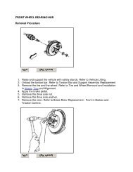
VALVE CLEARANCE (1MZ−FE)<br />
VALVE CLEARANCE (1MZ−FE)<br />
ADJUSTMENT<br />
1. DRAIN COOLANT (See page 16−22)<br />
2. REMOVE FRONT FENDER APRON SEAL RH<br />
3. REMOVE V−BANK COVER (See page 14−199)<br />
4. REMOVE RADIATOR HOSE INLET<br />
5. REMOVE FRONT SUSPENSION BRACE SUB−ASSY UPPER CENTER<br />
6. REMOVE AIR CLEANER ASSEMBLY WITH HOSE (See page 10−13)<br />
1405H−03<br />
7. REMOVE INTAKE AIR SURGE TANK<br />
(a) Disconnect the accelerator cable.<br />
(b) Remove the bolt, and disconnect the speed control cable<br />
with the bracket.<br />
(c) Disconnect the throttle position sensor connector.<br />
(d) Disconnect the IAC <strong>valve</strong> connector.<br />
(e) Remove the 3 bolts, and disconnect the PS pressure tube<br />
from the intake air surge tank, throttle body bracket and<br />
No.1 engine hanger.<br />
(f)<br />
Disconnect the 2 water bypass hoses and No.6 air hose.<br />
A36458<br />
(g)<br />
Disconnect the purge hose.<br />
A52824<br />
Author:<br />
Date:<br />
1509
ENGINE MECHANICAL<br />
−<br />
VALVE CLEARANCE (1MZ−FE)<br />
14−131<br />
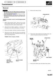
(h)<br />
Disconnect the hoses and cables.<br />
A52841<br />
Engine<br />
Hanger<br />
(i)<br />
(j)<br />
Remove the 2 bolts and No.1 engine hanger.<br />
Remove the 2 bolts and throttle body bracket.<br />
Throttle Body<br />
Bracket<br />
A52842<br />
(k) Disconnect the engine wire from emission control <strong>valve</strong><br />
set.<br />
(l) Using an 8 mm socket hexagon wrench, remove the 2<br />
bolts, 2 nuts and intake air surge tank.<br />
A05073<br />
8. REMOVE IGNITION COIL ASSY<br />
9. REMOVE CYLINDER HEAD COVER SUB−ASSY<br />
10. REMOVE CYLINDER HEAD COVER SUB−ASSY LH<br />
(a) Using a E6 torx socket wrench, remove the 2 bolts, and<br />
disconnect the engine wire protector.<br />
(b) Remove the 9 bolts and cylinder head cover.<br />
A36719<br />
Author:<br />
Date:<br />
1510
14−132<br />
ENGINE MECHANICAL<br />
−<br />
VALVE CLEARANCE (1MZ−FE)<br />
11. INSPECT VALVE CLEARANCE<br />
(a) Turn the crankshaft pulley, and align its groove with the<br />
timing mark ”0” of the No. 1 timing belt cover.<br />
(b) Check that the <strong>valve</strong> lifters on the No. 1 (IN and EX) are<br />
loose.<br />
If not, turn the crankshaft 1 revolution (360) and align the mark<br />
as above.<br />
P18805<br />
RH Bank<br />
EX<br />
IN<br />
1<br />
LH Bank<br />
1<br />
3<br />
3<br />
Front<br />
(c)<br />
Check only those <strong>valve</strong>s indicated in the illustration.<br />
(1) Using a feeler gauge, measure the <strong>clearance</strong> between<br />
the <strong>valve</strong> lifter and camshaft.<br />
Valve <strong>clearance</strong> (Cold):<br />
Intake 0.15 − 0.25 mm (0.006 − 0.010 in.)<br />
Exhaust 0.25 − 0.35 mm (0.010 − 0.014 in.)<br />
(2) Record out−of−specification <strong>valve</strong> <strong>clearance</strong> measurements.<br />
They will be used later to determine the<br />
required replacement adjusting shim.<br />
IN<br />
EX<br />
2<br />
2<br />
A05273<br />
RH Bank<br />
EX<br />
IN<br />
LH Bank<br />
2<br />
2<br />
3 3<br />
Front<br />
5<br />
5<br />
(d)<br />
Turn the crankshaft 2/3 of a revolution (240), and check<br />
only the <strong>valve</strong>s indicated in the illustration.<br />
(1) Using a feeler gauge, measure the <strong>clearance</strong> between<br />
the <strong>valve</strong> lifter and camshaft.<br />
Valve <strong>clearance</strong> (Cold):<br />
Intake 0.15 − 0.25 mm (0.006 − 0.010 in.)<br />
Exhaust 0.25 − 0.35 mm (0.010 − 0.014 in.)<br />
(2) Record out−of−specification <strong>valve</strong> <strong>clearance</strong> measurements.<br />
They will be used later to determine the<br />
required replacement adjusting shim.<br />
IN<br />
EX<br />
4<br />
4<br />
A05272<br />
Author:<br />
Date:<br />
1511
ENGINE MECHANICAL<br />
−<br />
VALVE CLEARANCE (1MZ−FE)<br />
14−133<br />
RH Bank<br />
EX<br />
IN<br />
LH Bank<br />
1 1<br />
Front<br />
4 4<br />
5<br />
5<br />
(e)<br />
Turn the crankshaft 2/3 of a revolution (240), and check<br />
only the <strong>valve</strong>s indicated in the illustration.<br />
(1) Using a feeler gauge, measure the <strong>clearance</strong> between<br />
the <strong>valve</strong> lifter and camshaft.<br />
Valve <strong>clearance</strong> (Cold):<br />
Intake 0.15 − 0.25 mm (0.006 − 0.010 in.)<br />
Exhaust 0.25 − 0.35 mm (0.010 − 0.014 in.)<br />
(2) Record out−of−specification <strong>valve</strong> <strong>clearance</strong> measurements.<br />
They will be used later to determine the<br />
required replacement adjusting shim.<br />
IN<br />
EX<br />
6<br />
6<br />
A05274<br />
Upward<br />
12. ADJUST VALVE CLEARANCE<br />
(a) Turn the camshaft so that the cam lobe for the <strong>valve</strong> to be<br />
adjusted faces up.<br />
(b) Turn the <strong>valve</strong> lifter with a screwdriver so that the notches<br />
are perpendicular to the camshaft.<br />
Notch<br />
P12919<br />
Front of No. 1 and No. 2 cylinders<br />
SST (A)<br />
SST (B)<br />
7<br />
Others<br />
SST (A)<br />
(c) Using SST (A), press down the <strong>valve</strong> lifter and place SST<br />
(B) between the camshaft and <strong>valve</strong> lifter. Remove SST<br />
(A).<br />
SST 09248−55040 (09248−05410, 09248−05420)<br />
HINT:<br />
Apply SST (B) at a slight angle on the side marked with<br />
”9” or ”7”, at the position shown in the illustration.<br />
When SST (B) is inserted too deeply, it will get pinched by<br />
the shim. To prevent it from being stuck, insert it gently<br />
from the intake side, at a slight angle.<br />
SST (A)<br />
SST (B)<br />
09248−05410<br />
09248−05420<br />
SST (B)<br />
9<br />
A52819<br />
Author:<br />
Date:<br />
1512
14−134<br />
ENGINE MECHANICAL<br />
−<br />
VALVE CLEARANCE (1MZ−FE)<br />
SST (B)<br />
(d)<br />
Using a small screwdriver and magnetic finger, remove<br />
the adjusting shim.<br />
Magnetic Finger<br />
A52822<br />
EM0494<br />
(e)<br />
(f)<br />
(g)<br />
Using a micrometer, measure the thickness of the removed<br />
shim.<br />
Calculate the thickness of a new shim so the <strong>valve</strong> <strong>clearance</strong><br />
comes within the specified value.<br />
A<br />
B<br />
C<br />
Thickness of new shim<br />
Thickness of used shim<br />
Measured <strong>valve</strong> <strong>clearance</strong><br />
Specified value (Cold):<br />
Intake A = B + (C − 0.20 mm (0.008 in.))<br />
Exhaust A = B + (C − 0.30 mm (0.012 in.))<br />
Select a new shim with a thickness as close as possible<br />
to the calculated values.<br />
EXAMPLE (Intake):<br />
Measured <strong>valve</strong> <strong>clearance</strong> = 0.45 mm (0.0177 in.)<br />
0.45 mm (0.0177 in.) − 0.20 mm (0.0079 in.) = 0.25 mm (0.0098 in.)<br />
(Measured − Specification = Excess <strong>clearance</strong>)<br />
Used shim measurement = 2.80 mm (0.1102 in.)<br />
0.25 mm (0.0098 in.) + 2.80 mm (0.1102 in.) = 3.05 mm (0.1201 in.)<br />
(Excess <strong>clearance</strong> + Used shim = Ideal new shim)<br />
Closest new shim = 3.05 mm (0.1201 in.)<br />
Select No. 12 shim<br />
HINT:<br />
Shims are available in 17 sizes in increments of 0.05 mm<br />
(0.0020 in.), from 2.50 mm (0.0984 in.) to 3.30 mm<br />
(0.1299 in.).<br />
Refer to adjusting shim selection chart on the following 2<br />
pages.<br />
Author:<br />
Date:<br />
1513
ENGINE MECHANICAL<br />
−<br />
VALVE CLEARANCE (1MZ−FE)<br />
14−135<br />
<br />
Installed shim thickness<br />
mm (in.)<br />
Measured <strong>clearance</strong><br />
mm (in.)<br />
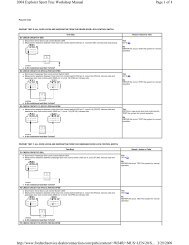
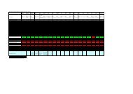
Adjusting Shim Selection Chart (Intake)<br />
Intake <strong>valve</strong> <strong>clearance</strong> (Cold):<br />
0.15 to 0.25 mm (0.006 to 0.010 in.)<br />
EXAMPLE:<br />
The 2.800 mm (0.1102 in.) shim is installed, and the measured<br />
<strong>clearance</strong> is 0.450 mm (0.0177 in.). Replace the 2.800 mm<br />
(0.1102 in.) shim with a new No. 12 shim.<br />
Shim<br />
No.<br />
New shim thickness mm (in.)<br />
Shim<br />
Thickness Thickness<br />
No.<br />
HINT:<br />
A shim’s thickness is written on its face in<br />
millimeters.<br />
V00719<br />
Author:<br />
Date:<br />
1514
14−136<br />
ENGINE MECHANICAL<br />
−<br />
VALVE CLEARANCE (1MZ−FE)<br />
<br />
Installed shim thickness<br />
mm (in.)<br />
Measured <strong>clearance</strong><br />
mm (in.)<br />
Adjusting Shim Selection Chart (Exhaust)<br />
Exhaust <strong>valve</strong> <strong>clearance</strong> (Cold):<br />
0.25 to 0.35 mm (0.010 to 0.014 in.)<br />
EXAMPLE:<br />
The 2.800 mm (0.1102 in.) shim is installed, and the measured<br />
<strong>clearance</strong> is 0.450 mm (0.0177 in.). Replace the 2.800 mm<br />
(0.1102 in.) shim with a new No. 10 shim.<br />
New shim thickness mm (in.)<br />
Shim<br />
No.<br />
Shim<br />
Thickness Thickness<br />
No.<br />
HINT:<br />
A shim’s thickness is written on its face in<br />
millimeters.<br />
V00720<br />
Author:<br />
Date:<br />
1515
ENGINE MECHANICAL<br />
−<br />
VALVE CLEARANCE (1MZ−FE)<br />
14−136−1<br />
SST (B)<br />
SST (A)<br />
(h)<br />
(i)<br />
(j)<br />
Place a new adjusting shim on the <strong>valve</strong> lifter, with imprinted<br />
numbers facing down.<br />
Press down the <strong>valve</strong> lifter with SST (A), and remove SST<br />
(B).<br />
SST 09248−55040 (09248−05410, 09248−05420)<br />
Recheck the <strong>valve</strong> <strong>clearance</strong>.<br />
A52820<br />
: Seal Packing<br />
Front<br />
A52836<br />
13. INSTALL CYLINDER HEAD COVER SUB−ASSY<br />
(a) Apply seal packing to the cylinder head as shown in the<br />
illustration.<br />
Seal packing: Part No. 08826−00080 or equivalent<br />
NOTICE:<br />
Remove any oil from the contact surface.<br />
Install the cylinder head cover within 3 minutes after<br />
applying seal packing.<br />
Do not start the engine within 2 hours after installing.<br />
(b) Install the cylinder head cover with the 9 bolts. Uniformly<br />
tighten the bolts, in several passes.<br />
Torque: 8.0 N⋅m (82 kgf⋅cm, 71 in.⋅lbf)<br />
14. INSTALL CYLINDER HEAD COVER SUB−ASSY LH<br />
: Seal Packing<br />
(a) Apply seal packing to the cylinder head as shown in the<br />
illustration.<br />
Seal packing: Part No. 08826−00080 or equivalent<br />
NOTICE:<br />
Remove any oil from the contact surface.<br />
Install the cylinder head cover within 3 minutes after<br />
Front<br />
applying seal packing.<br />
A52837 Do not start the engine within 2 hours after installing.<br />
(b) Install the cylinder head cover with the 9 bolts. Uniformly<br />
tighten the bolts, in several passes.<br />
Torque: 8.0 N⋅m (82 kgf⋅cm, 71 in.⋅lbf)<br />
15. INSTALL IGNITION COIL ASSY<br />
Torque: 8.0 N⋅m (82 kgf⋅cm, 71 in.⋅lbf)<br />
16. INSTALL INTAKE AIR SURGE TANK<br />
(a) Using an 8 mm hexagon wrench, install a new gasket and<br />
the air intake chamber assembly with the 2 bolts and 2<br />
nuts. Uniformly tighten the bolts and nuts in several<br />
passes.<br />
Torque: 43 N⋅m (438 kgf⋅cm, 32 ft⋅lbf)<br />
A05073<br />
Author:<br />
Date:<br />
1516
14−136−2<br />
ENGINE MECHANICAL<br />
−<br />
VALVE CLEARANCE (1MZ−FE)<br />
Engine<br />
Hanger<br />
Throttle Body<br />
Bracket<br />
(b)<br />
(c)<br />
Install the No.1 engine hanger with the 2 bolts.<br />
Torque: 39 N⋅m (400 kgf⋅cm, 19 ft⋅lbf)<br />
Install the throttle body bracket with the 2 bolts.<br />
Torque: 20 N⋅m (199 kgf⋅cm, 14 ft⋅lbf)<br />
A52842<br />
17. INSTALL AIR CLEANER ASSEMBLY WITH HOSE (See page 10−13)<br />
18. CONNECT VACUUM HOSE<br />
19. INSTALL FRONT SUSPENSION BRACE SUB−ASSY UPPER CENTER<br />
Torque: 80 N⋅m (816 kgf⋅cm, 59 ft⋅lbf)<br />
20. INSTALL V−BANK COVER (See page 14−199)<br />
21. ADD COOLANT (See page 16−22)<br />
22. INSPECT FOR ENGINE COOLANT LEAKS (See page 16−13)<br />
Author:<br />
Date:<br />
1517