Druckschrift 99810560, Combiners and Filters for FM ... - Kathrein
Druckschrift 99810560, Combiners and Filters for FM ... - Kathrein
Druckschrift 99810560, Combiners and Filters for FM ... - Kathrein

Create successful ePaper yourself
Turn your PDF publications into a flip-book with our unique Google optimized e-Paper software.
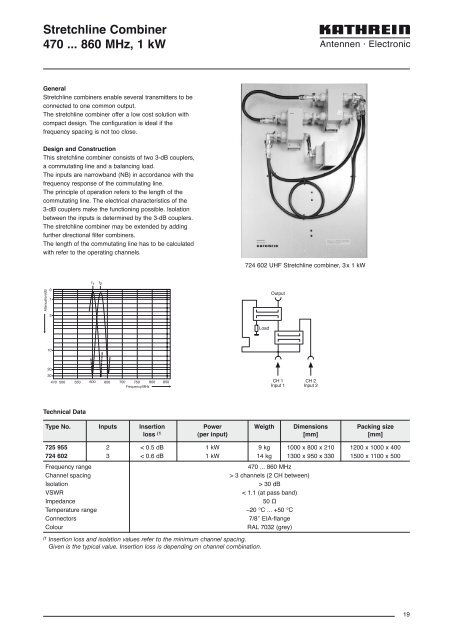
Stretchline Combiner<br />
470 ... 860 MHz, 1 kW<br />
General<br />
Stretchline combiners enable several transmitters to be<br />
connected to one common output.<br />
The stretchline combiner offer a low cost solution with<br />
compact design. The configuration is ideal if the<br />
frequency spacing is not too close.<br />
Design <strong>and</strong> Construction<br />
This stretchline combiner consists of two 3-dB couplers,<br />
a commutating line <strong>and</strong> a balancing load.<br />
The inputs are narrowb<strong>and</strong> (NB) in accordance with the<br />
frequency response of the commutating line.<br />
The principle of operation refers to the length of the<br />
commutating line. The electrical characteristics of the<br />
3-dB couplers make the functioning possible. Isolation<br />
between the inputs is determined by the 3-dB couplers.<br />
The stretchline combiner may be extended by adding<br />
further directional filter combiners.<br />
The length of the commutating line has to be calculated<br />
with refer to the operating channels.<br />
724 602 UHF Stretchline combiner, 3x 1 kW<br />
f 1 f 2<br />
Output<br />
Attenuation/dB<br />
0<br />
1<br />
3<br />
Load<br />
10<br />
20<br />
30<br />
470 500<br />
550<br />
600<br />
650<br />
700 750 800<br />
Frequency/MHz<br />
850<br />
CH 1<br />
Input 1<br />
CH 2<br />
Input 2<br />
Technical Data<br />
Type No. Inputs Insertion Power Weigth Dimensions Packing size<br />
loss (1 (per input) [mm] [mm]<br />
725 955 2 < 0.5 dB 1 kW 9 kg 1000 x 800 x 210 1200 x 1000 x 400<br />
724 602 3 < 0.6 dB 1 kW 14 kg 1300 x 950 x 330 1500 x 1100 x 500<br />
Frequency range<br />
470 ... 860 MHz<br />
Channel spacing<br />
> 3 channels (2 CH between)<br />
Isolation<br />
> 30 dB<br />
VSWR<br />
< 1.1 (at pass b<strong>and</strong>)<br />
Impedance<br />
50 Ω<br />
Temperature range –20 °C ... +50 °C<br />
Connectors<br />
7/8″ EIA-flange<br />
Colour<br />
RAL 7032 (grey)<br />
(1 Insertion loss <strong>and</strong> isolation values refer to the minimum channel spacing.<br />
Given is the typical value. Insertion loss is depending on channel combination.<br />
19