Druckschrift 99810560, Combiners and Filters for FM ... - Kathrein
Druckschrift 99810560, Combiners and Filters for FM ... - Kathrein
Druckschrift 99810560, Combiners and Filters for FM ... - Kathrein

Create successful ePaper yourself
Turn your PDF publications into a flip-book with our unique Google optimized e-Paper software.
Technical Annex<br />
<strong>Filters</strong><br />
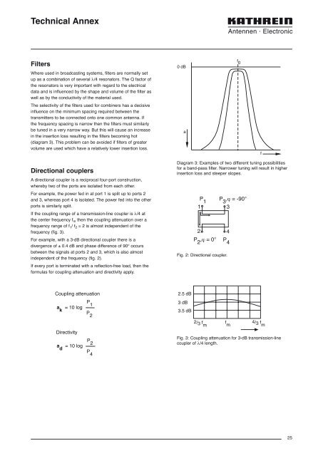
Where used in broadcasting systems, filters are normally set<br />
up as a combination of several λ/4 resonators. The Q factor of<br />
the resonators is very important with regard to the electrical<br />
data <strong>and</strong> is influenced by the shape <strong>and</strong> volume of the filter as<br />
well as by the conductivity of the material used.<br />
The selectivity of the filters used <strong>for</strong> combiners has a decisive<br />
influence on the minimum spacing required between the<br />
transmitters to be connected onto one common antenna. If<br />
the frequency spacing is narrow then the filters must similarly<br />
be tuned in a very narrow way. But this will cause an increase<br />
in the insertion loss resulting in the filters becoming hot<br />
(diagram 3). This problem can be avoided if filters of greater<br />
volume are used which have a relatively lower insertion loss.<br />
0 dB<br />
a<br />
f 0<br />
f<br />
Directional couplers<br />
A directional coupler is a reciprocal four-port construction,<br />
whereby two of the ports are isolated from each other.<br />
For example, the power fed in at port 1 is split up to ports 2<br />
<strong>and</strong> 3, whereas port 4 is isolated. The power fed into the other<br />
ports is similarly split.<br />
If the coupling range of a transmission-line coupler is λ/4 at<br />
the center frequency f m then the coupling attenuation over a<br />
frequency range of f 1 / f 2 = 2 is almost independent of the<br />
frequency (fig. 3).<br />
For example, with a 3-dB directional coupler there is a<br />
divergence of ± 0.4 dB <strong>and</strong> phase difference of 90° occurs<br />
between the signals at ports 2 <strong>and</strong> 3, which is also almost<br />
independent of the frequency (fig. 2).<br />
If every port is terminated with a reflection-free load, then the<br />
<strong>for</strong>mulas <strong>for</strong> coupling attenuation <strong>and</strong> directivity apply.<br />
Diagram 3: Examples of two different tuning possibilities<br />
<strong>for</strong> a b<strong>and</strong>-pass filter. Narrower tuning will result in higher<br />
insertion loss <strong>and</strong> steeper slopes.<br />
P 1<br />
1<br />
2<br />
P 2<br />
,ϕ = 0°<br />
Fig. 2: Directional coupler.<br />
P 3<br />
,ϕ = -90°<br />
P 4<br />
3<br />
4<br />
Coupling attenuation<br />
2.5 dB<br />
a k<br />
= 10 log<br />
P 1<br />
P 2<br />
3 dB<br />
3.5 dB<br />
Directivity<br />
a d<br />
= 10 log<br />
P 2<br />
P 4<br />
2/3 f f m m<br />
4/3 f m<br />
Fig. 3: Coupling attenuation <strong>for</strong> 3-dB transmission-line<br />
coupler of λ/4 length.<br />
25