
Create successful ePaper yourself
Turn your PDF publications into a flip-book with our unique Google optimized e-Paper software.
Rev 0 – June 2012<br />
<strong>Key</strong> <strong>Digital</strong> ® , led by digital video pioneer Mike Tsinberg,<br />
develops and manufactures high quality, cutting-edge<br />
technology solutions for virtually all applications where<br />
high quality video imaging is important. <strong>Key</strong> <strong>Digital</strong> ®<br />
is at the forefront of the video industry for Home<br />
Theater Retailers, Custom Installers, System Integrators,<br />
Broadcasters, Manufacturers, and Consumers.<br />
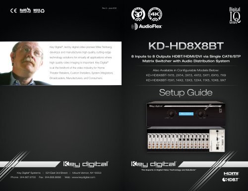
<strong>KD</strong>-<strong>HD8X8BT</strong><br />
8 Inputs to 8 Outputs HDBT/HDMI/DVI via Single CAT6/STP<br />
Matrix Switcher with Audio Distribution System<br />
Also Available in Configurable Models Below:<br />
<strong>KD</strong>-<strong>HD8X8BT</strong>-1X15, 2X14, 3X13, 4X12, 5X11, 6X10, 7X9<br />
<strong>KD</strong>-<strong>HD8X8BT</strong>-15X1, 14X2, 13X3, 12X4, 11X5, 10X6, 9X7<br />
Setup Guide<br />
<strong>Key</strong> <strong>Digital</strong> ® Systems :: 521 East 3rd Street :: Mount Vernon, NY 10553<br />
Phone : 914.667.9700 Fax : 914.668.8666 Web : www.keydigital.com<br />
The Experts in <strong>Digital</strong> Video Technology and Solutions
2 3<br />
Table of Contents<br />
1. About <strong>KD</strong>-<strong>HD8X8BT</strong>. ....................................................... 3<br />
2. Connections, LEDs and Button Map ........................................... 4<br />
3. Application Example. ....................................................... 6<br />
4. Quick Setup Guide. ........................................................ 7<br />
5. EDID Control .............................................................11<br />
6. Advanced Switching Options .................................................13<br />
7. Audio Distribution Features ...................................................17<br />
8. Control Routing via <strong>Digital</strong> IQ ................................................19<br />
9. <strong>Digital</strong> IQ Control Routing with Compass Control System ............................24<br />
10. IR Remote Command List ................................................. 28<br />
10. RS-232 Control Codes .................................................... 29<br />
11. Firmware Update Wizard ................................................... 32<br />
12. Specifications. .......................................................... 34<br />
13. Important Product Warnings & Safety Instructions. ............................... 36<br />
14. How to Contact <strong>Key</strong> <strong>Digital</strong> ® ................................................ 37<br />
15. Warranty Information. ..................................................... 38<br />
Always follow the instructions provided in this Operating Manual.<br />
© 2012 <strong>Key</strong> <strong>Digital</strong>, Inc. All rights reserved.<br />
1. About <strong>KD</strong>-<strong>HD8X8BT</strong><br />
<strong>Key</strong> <strong>Digital</strong> ® <strong>Digital</strong> IQ Series <strong>KD</strong>-<strong>HD8X8BT</strong> is a HDBT/HDMI/DVI Matrix Switcher capable<br />
of switching up to 8 HDMI/DVI Video Sources/Inputs to 8 independent Zones/Outputs via<br />
HDMI/DVI and CAT6/STP. Features card slot architecture providing flexible Input/Output<br />
configurations.<br />
Advanced HDMI ® Features<br />
½½<br />
3D – Capability to pass 3D stereoscopic signal formats<br />
½½<br />
4K – 4096x2160/24 video resolution support for commercial applications such as <strong>Digital</strong> Movie<br />
Theaters, CAD, Post Production, Graphics, etc.<br />
<strong>Key</strong> Features<br />
½½<br />
Full switching of 5 independent matrixes: Video, Analog/<strong>Digital</strong> Audio, HDMI Audio, IR, RS-232<br />
½½<br />
Control routing function to source/destination connections for Bi-Directional IR and RS-232<br />
Control adds approximately 32 ports to <strong>KD</strong>-MC2500 Master Controller<br />
½½<br />
Supports all SD, HD, and VESA (VGA, SVGA, XGA, WXGA, SXGA, UXGA) resolutions up to<br />
1080p (60Hz & 50Hz)<br />
½½<br />
Internal EDID Library features 12 default EDID configurations, in addition to Native EDID data for<br />
any Output/Display<br />
½½<br />
TMDS re-clock for support of long HDMI/DVI or CAT6/STP connections and daisy chain<br />
configurations<br />
½½<br />
Full Buffer Technology – Full matrix buffering of HDCP and EDID for seamless switching and<br />
viewing of any source/input with any display/output, regardless of multiple output viewing relation<br />
½½<br />
Supports switching of lossless compressed digital audio:<br />
»»<br />
Dolby ® TrueHD, Dolby ® <strong>Digital</strong> Plus and DTS -HD Master Audio<br />
½½<br />
AudioFlex System – system in which Multi-Channel audio can be routed to capable zones,<br />
while 2-Channel audio is routed to zones with this requirement<br />
½½<br />
Flexible I/O configuration from 1x15 to 15x1 and multi-unit configurations from 8x16 to 32x32<br />
½½<br />
CAT6 outputs implement HDBaseT ® format<br />
<strong>Key</strong> Benefits<br />
½½<br />
Transmits 1080p/60Hz signals up to 400 ft. and 1080p/24, 1080i, 720p signals up to 600 ft.<br />
when used with <strong>KD</strong>-CATHD500Rx receive baluns and <strong>KD</strong>-CAT6STP1X CAT6/STP cabling.<br />
Compatible with third-party CAT6/STP with lesser distance performance.<br />
½½<br />
Fully automatic CAT6/STP cable equalization<br />
½½<br />
16 active outputs (8 HDMI/DVI and 8 CAT6/STP) enable flexible integration<br />
½½<br />
Full Audio control per output for volume, treble, bass, balance, and lip-sync for 2-ch stereo<br />
formats from analog or digital sources<br />
½½<br />
Serial IR, Optical IR, Front Panel & RS-232 control. Supports major control systems such as<br />
Compass Control ® , AMX ® , Control4 ® , Crestron ® , RTI ® , Universal ® .<br />
Accessories<br />
»»<br />
External +12V/8.33A (100W) Power Supply – <strong>KD</strong>-PS12V8A<br />
»»<br />
IR Remote control with two batteries; HDMI Cable Clips (16); 6 ft. USB Data Cable
4 5<br />
2. Connections, LEDs and Button Map<br />
Front Panel<br />
Main Control Panel<br />
Operation Mode Switch<br />
Switch to “Program” mode<br />
when updating firmware<br />
Rear IR Eye (Receiver)<br />
Rear IR receiver for<br />
remote control<br />
Power<br />
12V/8.33A (100W)<br />
Power Supply<br />
Left Selector<br />
Use to access Main Menu<br />
and select sub-menu choices.<br />
(see Quick Setup Guide section<br />
for more information)<br />
LCD Screen<br />
Displays Menu selections, Input and<br />
Output information, system settings and<br />
status information<br />
Right Selector<br />
Use to access sub-menus<br />
within the Main Menu.<br />
(see Quick Setup Guide<br />
section for more information)<br />
IR Eye<br />
TCP/IP<br />
This is the main TCP/IP port for interfacing<br />
with control systems. It supports the same<br />
control commands as the RS-232 port<br />
and it can support TCP/IP to RS-232<br />
conversion & routing.<br />
USB<br />
The USB port is for<br />
software upgrades<br />
only. It is not used for<br />
control interface.<br />
RS-232<br />
The main RS-232/DB9<br />
port for interfacing with<br />
a control system.<br />
Serial IR<br />
To Input from Control interface<br />
for controlling unit via Serial IR<br />
and IR routing<br />
HDMI Input and Output Numbering<br />
Generically configured, <strong>KD</strong>-<strong>HD8X8BT</strong> contains 8 Input cards and 8 Output cards. The Input cards<br />
are addressed from 01-08, and the Output cards from 01-08.<br />
Rear Panel<br />
Rx Input Card (<strong>KD</strong>-HD8x8BTIC)<br />
Looking at the rear panel, card slots are numbered from left to right<br />
Left Analog Audio / PCM Audio Input<br />
Supports Left channel Analog Audio Input or<br />
use for Coaxial <strong>Digital</strong> Audio Input<br />
HDMI Input<br />
To Input source components<br />
Right Analog Audio Input<br />
Supports Right channel Analog Audio Input<br />
Serial IR / RS-232<br />
Use the <strong>KD</strong>-<strong>HD8X8BT</strong> as a Control Router for<br />
devices integrated into your system<br />
Link LED<br />
Indicates that input connection is stable<br />
Input Cards 1-8 (<strong>KD</strong>-HD8x8BTIC)<br />
Please see p. 5 for detailed description<br />
Output Cards 1-8 (<strong>KD</strong>-HD8x8BTOC)<br />
Please see p. 5 for detailed description<br />
Main Control Panel<br />
Please see p. 5 for<br />
detailed description<br />
Tx Output Card (<strong>KD</strong>-HD8x8BTOC)<br />
Left Analog Audio / PCM Audio Output<br />
Send Left channel Analog Audio or Coaxial<br />
<strong>Digital</strong> Audio to your Display or other devices<br />
CAT6/STP Output<br />
Use the <strong>KD</strong>-CATHD500Rx Receive Balun to carry Video,<br />
Audio, and Control to your Display (or other) devices<br />
HDMI Output<br />
To Output to Display<br />
Right Analog Audio Output<br />
Send Right channel Analog Audio<br />
to your Receiver or other devices<br />
Serial IR / RS-232<br />
Use the <strong>KD</strong>-<strong>HD8X8BT</strong> as a Control Router for<br />
devices integrated into your system<br />
Link LED<br />
Indicates that output connection is stable
6 7<br />
3. Application Example<br />
Desktop PC<br />
VGA<br />
HDMI<br />
L/R/PCM<br />
<strong>KD</strong>-VP1250<br />
HDMI<br />
Transmits:<br />
»1080p/60Hz resolution up to 400 ft.<br />
»1080p/24, 1080i, 720p and 480i/p resolutions up to 600 ft.<br />
» When used with <strong>KD</strong>-CATHD500Rx Receiver Baluns<br />
and <strong>KD</strong>-CAT6STP1X cabling<br />
CAT6/STP<br />
HDMI/DVI<br />
Audio<br />
IR/RS-232<br />
VGA<br />
570’<br />
<strong>KD</strong>-CATHD500<br />
IR<br />
Display 1a<br />
(mirrored)<br />
Apple TV<br />
HDMI<br />
IR<br />
480’<br />
<strong>KD</strong>-CATHD500<br />
HDMI<br />
IR<br />
Satellite 1<br />
CAT6/STP<br />
HDMI<br />
IR/RS-232<br />
Display 2a<br />
(mirrored)<br />
IR<br />
<strong>KD</strong>-<strong>HD8X8BT</strong><br />
HDMI<br />
Display 1 Display 2<br />
Display 4<br />
Display 6<br />
CAT6/STP<br />
IR/RS-232<br />
HDMI<br />
Display 3<br />
Satellite 2 Cable 1 Cable 2<br />
HDMI<br />
IR<br />
RS-232<br />
HDMI<br />
RS-232<br />
HDMI<br />
IR<br />
HDMI<br />
IR/RS-232<br />
HDMI<br />
HDMI<br />
IR/RS-232<br />
RS232 Control<br />
L/R/PCM<br />
CAT6/STP<br />
Serial IR<br />
Optical IR<br />
Display 5<br />
IR/RS-232<br />
IR<br />
HDMI<br />
CAT6/STP<br />
L/R/PCM<br />
Blu-Ray<br />
Blu-Ray<br />
IR<br />
HDMI<br />
IR<br />
HDMI<br />
<strong>KD</strong>-MC2500<br />
IR<br />
RS-232<br />
RS-232<br />
USB<br />
TCP/IP<br />
500’<br />
450’<br />
Surround Rcvr.<br />
<strong>KD</strong>-CATHD500 <strong>KD</strong>-CATHD500<br />
IR<br />
HDMI<br />
IR<br />
HDMI<br />
Display 7<br />
Display 8<br />
4. Quick Setup Guide<br />
Initial Setup & Operation for HDMI via Front Panel<br />
1. Connect Input & Output Devices<br />
»»<br />
Slots 1-8 are labeled Rx, and are Input Card Slots 1-8.<br />
»»<br />
Slots 9-16 are labeled Tx, and are Output Card Slots 1-8.<br />
»»<br />
Connect your source components to the Input cards<br />
»»<br />
Connect your displays to the Output cards<br />
»»<br />
For output devices connected via CAT6/STP, use <strong>KD</strong>-CATHD500Rx via the RJ45 port<br />
»»<br />
Power up all sources and displays<br />
2. Establish an HDMI Handshake for Each Source<br />
»»<br />
Push the left selector to access the Main Menu choices<br />
»»<br />
Using the left selector, scroll to the “EDID Setup” Menu<br />
»»<br />
Press the right selector to navigate to the EDID sub-menus<br />
»»<br />
With the left selector, scroll to the Input source you wish to provide the EDID to<br />
»»<br />
Using the right selector, scroll to the HDMI or CAT6/STP Output you wish to establish an<br />
HDMI handshake from, or select a Default EDID 01-12 from the EDID library<br />
»»<br />
Press the right selector to set the Handshake for that combination<br />
»»<br />
Continue this procedure for all Inputs<br />
»»<br />
The EDID control and HDMI input set up is stored in a non-volatile memory back up and is<br />
only required during initial set up or when a new display or source is added to the system.<br />
»»<br />
Establish a default handshake for ALL Inputs:<br />
»»<br />
Using the ‘EDID Setup’ Menu, select ‘ALL Inputs’ and scroll to the Output number<br />
you wish to copy the EDID from (HDMI, CAT6/STP or a Default EDID setting) and press<br />
the right selector<br />
3. Switching via Front Panel<br />
»»<br />
Push the left selector to access the Main Menu choices<br />
»»<br />
Using the left selector, scroll to the “Video Switch” Menu<br />
»»<br />
Press the right selector to navigate to the Video Switch sub-menus<br />
»»<br />
Using the left selector, scroll to the Output you wish to select<br />
»»<br />
Using the right selector, scroll to the Input you wish to select<br />
»»<br />
Finally, press the right selector to make the switch<br />
4. Sending your output via <strong>KD</strong>-CATHD500Rx CAT6/STP Receive Balun(s)<br />
»»<br />
Both HDMI and CAT6/STP Outputs are active on all Output Card Slots, therefore no<br />
configuration is necessary to activate the CAT6/STP Output for each Tx Card Slot.
8 9<br />
Front Panel Menu Selection Controls:<br />
Power On<br />
½½<br />
The unit will power up with a push on either the left or right Selector.<br />
Power Off<br />
½½<br />
The unit will power off through IR, Remote, RS-232 or TCP/IP commands only.<br />
Left Selector<br />
½½<br />
Main Menu: To access the Main Menu push this selector once.<br />
½½<br />
To Select Main Menu Options: Turn selector left or right to select Menu Options<br />
½½<br />
Sub-Menu values: Turn this selector to scroll through the sub-menu selections. There will be left<br />
and right sub-menu choices. Use the left selector to change left side options<br />
½½<br />
To Go-Back to a previous menu: from whatever menu you are presently in you may return to the<br />
previous menu by pressing this selector once. You will return to the menu you were previously in.<br />
Right Selector<br />
½½<br />
Sub-Menu: After selecting a specific Main Menu (1-9) option with the left selector, press the right<br />
selector to select its Sub-Menu. You will be taken to the sub-menu for the main menu option you<br />
had previously selected.<br />
½½<br />
Sub-Menu values: Turn this selector to scroll through the sub-menu selections. Use the right<br />
selector to change right side options. After a sub-menu choice has been made, push this<br />
selector once to enter it. The display will blink to acknowledge your choice.<br />
Menu Tree on LCD Display<br />
Main Menu Selections:<br />
Using the left selector, choose from the following Main Menu options;<br />
1. Video Switch<br />
2. Audio Switch<br />
3. Volume Control<br />
4. Audio Output Set Up<br />
5. Audio Input Set Up<br />
6. EDID Set Up<br />
7. TCP/IP Set Up<br />
8. Factory Default<br />
Using the right selector, push to enter the sub-menu for any of the selected main menu options<br />
above;<br />
Sub-Menu Selections:<br />
1. “Video Switch” options:<br />
»»<br />
Output 01–08<br />
»»<br />
All Outputs<br />
Use the left selector to choose these.<br />
For each Output number selected, ‘01-08’ and ‘All’, there are Input sub-menu choices;<br />
»»<br />
Input 01–08<br />
Use the right selector to choose these and push to confirm your choice for both<br />
Select an Output number with the left selector and then select an Input number you wish to feed<br />
that output by turning the right selector. Push the right selector to select that combination. The<br />
display will blink to acknowledge your choice. This will immediately switch your Output to the Input<br />
selected.<br />
2. “Audio Switch” options:<br />
»»<br />
Output 01-08 plus All Outputs<br />
Use the left selector to choose these.<br />
For each Output number selected, ’01-08’ and ‘All’, there are Audio Location sub-menu choices:<br />
»»<br />
HDMI<br />
»»<br />
External Analog<br />
»»<br />
External <strong>Digital</strong><br />
Use the right selector to choose these and push to confirm choice.<br />
These correspond to which Audio signal type will be passed to the selected Output number from<br />
your previously selected Input number.<br />
3. “Volume Control Set Up” options:<br />
»»<br />
Output 01-08 plus All Outputs<br />
Use the left selector to choose Output number desired.<br />
Use the right selector to choose Volume level desired (00-99) and push to confirm choice.<br />
Continue for all Outputs you wish to change<br />
4. “Audio Output Set Up” options:<br />
»»<br />
Output 01-08 plus All Outputs<br />
Use the left selector to choose these.<br />
For each Output number selected, ’01-08’ and ‘All’, there are Audio Output sub-menu choices:<br />
»»<br />
<strong>Digital</strong><br />
»»<br />
Analog<br />
Use the right selector to choose these and push to confirm choice.<br />
These correspond to the RCA connectors only and choose which format will be passed to the<br />
Output selected.<br />
5. “Audio Input Set Up” options:<br />
»»<br />
Input 01-08 plus All Inputs<br />
Use the left selector to choose these.<br />
For each Input selected, ’01-08’ and ‘All’, there are Audio Input sub-menu choices;<br />
»»<br />
<strong>Digital</strong><br />
»»<br />
Analog<br />
Use the right selector to choose these and push to confirm choice.<br />
These correspond to the RCA connectors only and choose which format will be accepted by the<br />
Input selected.
10 11<br />
6. “EDID Set Up” options:<br />
»»<br />
Input 01-08 plus All Inputs<br />
Use the left selector to choose these.<br />
For each Input selected, ’01-08’ and ‘All’, there are EDID Set Up sub-menu choices:<br />
»»<br />
HDMI Output 01 through 08<br />
»»<br />
CAT6/STP Output 01 through 08<br />
»»<br />
For each Input (source) selected with the left selector there is a choice to copy the EDID<br />
information from either the HDMI or CAT6/STP connected Output (display) using the right<br />
selector depending on which is connected.<br />
»»<br />
The Default choices (listed below) copy the EDID from a stored library of EDID configurations<br />
to the selected Input card<br />
»»<br />
Default EDID 1 - (1080i Video, 2ch PCM Audio)<br />
»»<br />
Default EDID 2 - (1080i Video, DTS/DOLBY Audio)<br />
»»<br />
Default EDID 3 - (1080i Video, DTS/DOLBY/HD Audio)<br />
»»<br />
Default EDID 4 - (1080p Video, 2ch PCM)<br />
»»<br />
Default EDID 5 - (1080p Video, DTS/DOLBY Audio)<br />
»»<br />
Default EDID 6 - (1080p Video, DTS/DOLBY/HD Audio)<br />
»»<br />
Default EDID 7 - (3D/1080p Video, 2ch PCM)<br />
»»<br />
Default EDID 8 - (3D/1080p Video, DTS/DOLBY Audio)<br />
»»<br />
Default EDID 9 - (3D/1080p Video, DTS/DOLBY/HD Audio)<br />
»»<br />
Default EDID 10 - (DVI 1280x1024 Video, No Audio)<br />
»»<br />
Default EDID 11 - (DVI 1920x1080 Video, No Audio)<br />
»»<br />
Default EDID 12 - (DVI 1920x1200 Video, No Audio)<br />
Use the right selector to choose these and push to confirm choice. You will receive a “Completed”<br />
message when successful, or a “Failed” message if unsuccessful.<br />
7. “TCP / IP” options:<br />
»»<br />
IP address<br />
»»<br />
Sub net Mask<br />
»»<br />
Port<br />
½½<br />
The default IP address is; ‘192.168.000.233’ This can be changed to accommodate your<br />
particular configuration or controller.<br />
½½<br />
The default Sub net mask is ‘255.255.255.000’ and may also be changed to accommodate your<br />
particular configuration.<br />
½½<br />
The default Port number is ‘23’<br />
Select the TCP/IP option by pressing the right selector. Highlight the group of numbers you wish to<br />
change by turning the left selector. Change the group of numbers using the right selector. Continue<br />
this procedure until all numbers are chosen. Press the right selector to enter the changes. You may<br />
then press the left selector to return to the previous menu if desired.<br />
8. “Factory Default” options:<br />
This option will return the unit to its Factory Default settings. Please see the list of default settings<br />
below. When this menu option is chosen, you will be presented with a choice of EDID’s from the<br />
default EDID library. Choose one of these default EDID’s (typically default 1-1080i 2Ch PCM) using<br />
the left selector, then press the right selector to confirm. The unit will then reset to the default<br />
configuration including the EDID you have chosen.<br />
Factory Default Settings:<br />
»»<br />
Input = 1<br />
»»<br />
Input Audio = Analog<br />
»»<br />
Output Audio = Analog<br />
»»<br />
Audio = HDMI<br />
»»<br />
Port = HDMI<br />
»»<br />
Output Volume = 50<br />
»»<br />
Output Bass = 12<br />
»»<br />
Output Middle = 12<br />
»»<br />
Output Treble = 12<br />
»»<br />
Output Balance = 20<br />
»»<br />
Output Delay = 00<br />
»»<br />
EDID = Choice of default EDID library 01-12<br />
(see menu EDID Set Up for a list of default EDID choices pg.10)<br />
»»<br />
TCP / IP = 192.168.0.233<br />
5. EDID Control<br />
EDID Control HDMI Handshaking<br />
EDID (Extended Display Identification Data) is a data structure provided by a digital display to<br />
describe its capabilities to a video source. This data is also known as a “handshake” and typically<br />
includes manufacture name and serial number, product type, resolutions supported by the display,<br />
display size, pixel mapping data, etc.<br />
In a one-to-one source-display system, the EDID process is relatively simple. However, HDMI<br />
matrix systems enabled by the <strong>Digital</strong> IQ Series products are far more sophisticated as a source<br />
may be selected by multiple displays- with a variety of EDID information provided- at any given time.<br />
<strong>Key</strong> <strong>Digital</strong> EDID Control allows the integrator to choose the handshake that will be provided to<br />
each source device of the system. The EDID handshake is relayed to the source from the <strong>Digital</strong> IQ<br />
matrix, not from any of the displays/output devices of the system. This handshake will always be<br />
the EDID information that the source device receives.<br />
EDID Control handshaking can be provided to each source independently, or to all sources<br />
simultaneously.<br />
The EDID information is provided to a source in any of three methods:<br />
½½<br />
From the internal Default Library of EDID files located within the <strong>Digital</strong> IQ software<br />
½½<br />
From a copy of the EDID provided by any display/output device connected via the HDMI output<br />
connection<br />
½½<br />
From a copy of the EDID provided by any display/output device connected via the CAT6/STP<br />
output connection<br />
½½<br />
Providing an EDID Handshake from the Default Library:<br />
The Default Library features generic EDID handshakes that are compatible with a majority<br />
of source equipment and meet a wide-spectrum of demands desired in a variety of<br />
application types.<br />
½½<br />
The Default Library is subject to change as new standards and desired application updates are<br />
requested.
12 13<br />
½½<br />
The EDID Control library can be revised on your <strong>Digital</strong> IQ matrix via a firmware update. To verify<br />
the Default Library of your unit’s firmware, use the RS-232 Help command (“H”). See the RS-232<br />
Control Codes sections for more information.<br />
»»<br />
Default Library EDID Control Table:<br />
Default EDID 1 - (1080i Video, 2ch PCM Audio)<br />
Default EDID 2 - (1080i Video, DTS/DOLBY Audio)<br />
Default EDID 3 - (1080i Video, DTS/DOLBY/HD Audio)<br />
Default EDID 4 - (1080p Video, 2ch PCM)<br />
Default EDID 5 - (1080p Video, DTS/DOLBY Audio)<br />
Default EDID 6 - (1080p Video, DTS/DOLBY/HD Audio)<br />
Default EDID 7 - (3D/1080p Video, 2ch PCM)<br />
Default EDID 8 - (3D/1080p Video, DTS/DOLBY Audio)<br />
Default EDID 9 - (3D/1080p Video, DTS/DOLBY/HD Audio)<br />
Default EDID 10 - (DVI 1280x1024 Video, No Audio)<br />
Default EDID 11 - (DVI 1920x1080 Video, No Audio)<br />
Default EDID 12 - (DVI 1920x1200 Video, No Audio)<br />
½½<br />
After executing EDID Control handshaking for your system, it is recommended to observe video<br />
and audio performance in all zones.<br />
Providing a Default Library EDID handshake to a specified source:<br />
½½<br />
Via RS-232 (recommended):<br />
»»<br />
“SPCEDIDxxDyy”<br />
Where xx = input card number or “A” (all)<br />
Where yy = default library selection<br />
»»<br />
After giving the source device a few moments to adjust its output, you may verify the<br />
handshake has been properly received and the source has complied with the handshake by<br />
using the RS-232 Input status command “STPIxx”.<br />
½½<br />
Via the Front Panel:<br />
»»<br />
In the Main Menu, select “EDID Setup”<br />
»»<br />
Scroll to the Input Source (or all sources) that you wish to provide the Default EDID to. Press<br />
the selector knob to proceed.<br />
»»<br />
Scroll to the desired Default EDID number, using the Default EDID table or descriptive text as<br />
a reference. Press the selector knob to proceed and execute the EDID Control handshake.<br />
How to provide a copy of the EDID of any connected (HDMI or CAT6/STP) display/<br />
output device<br />
½½<br />
<strong>Digital</strong> IQ products are able to poll any connected output device for its EDID information and<br />
provide that EDID to the specified source.<br />
½½<br />
It is possible to poll any output device connected via the HDMI or CAT6/STP RJ45 output<br />
connections<br />
½½<br />
An exact copy of the EDID file provided by the specified output device is relayed to the specified<br />
source.<br />
½½<br />
This EDID file is not stored in the <strong>Digital</strong> IQ unit’s software. Therefore, it is not possible to<br />
relay the copy EDID of an output device unless it is connected at the time of prompting the<br />
handshake.<br />
½½<br />
Bear in mind that relaying an exact EDID handshake from one of the connected output devices<br />
may result in optimum performance in that respective output zone, but may also result in<br />
incompatibilities in other zones viewing that source with different display equipment.<br />
½½<br />
After executing EDID Control handshaking for your system, it is recommended to observe video<br />
and audio performance in all system zones.<br />
How to provide a copy EDID of any connected display/output device<br />
½½<br />
Via RS-232 (recommended):<br />
»»<br />
“SPCEDIDxxH/Cyy”<br />
Where xx = input card number or “A” (all)<br />
Where yy = Output card number (01-08)<br />
Where H or C = output device connected via HDMI (H) or CAT6/STP (C) output connection<br />
»»<br />
After giving the source device a few moments to adjust its output, you may verify the<br />
handshake has been properly received and the source has complied with the handshake by<br />
using the RS-232 Input status command “STPIxx”.<br />
½½<br />
Via the Front Panel:<br />
»»<br />
In the Main Menu, select “EDID Setup”<br />
»»<br />
Scroll to the Input Source (or all sources) that you wish to provide the copy EDID to. Press<br />
the selector knob to proceed.<br />
»»<br />
Scroll to the output number of the desired output device from which the EDID will be copied.<br />
Press the selector knob to proceed and execute the EDID Control handshake.<br />
6. Advanced Switching Options<br />
<strong>Digital</strong> IQ Series products deliver fully-independent matrix switching of video and audio.<br />
Additionally, there are multiple audio connections on each input card; HDMI, L/R Analog Audio<br />
and PCM <strong>Digital</strong> Audio. The L/R Analog and PCM <strong>Digital</strong> audio connections are referred to as the<br />
external audio connections.<br />
Each switching selection satisfies three variables:<br />
½½<br />
Video Input Card<br />
½½<br />
Audio Input Card<br />
½½<br />
Audio Input Location (ie. HDMI, L/R Analog, or PCM <strong>Digital</strong>)
17 18 19 20 21 22 23 24<br />
25 26 27 28 29 30 31 32<br />
14 15<br />
99<br />
A switching selection example which chooses Video on Input Card 01, and Audio on Input Card 01’s<br />
L/R Analog connection<br />
Although some Advanced Switching Options “SPCIR0917”<br />
are achievable via IR or Front-Panel control, it is<br />
IR<br />
recommended IR that you control your <strong>Digital</strong><br />
“SPCIR1018”<br />
IQ via RS-232 or TCP-IP if your application will utilize an<br />
“SPCRSS1119”<br />
RS-232<br />
CAT6/STP<br />
Advanced Switching<br />
<strong>KD</strong>-MC2500<br />
Option.<br />
<strong>KD</strong>-CATHD500Rx<br />
Systems that do not require independent video and audio matrix switching or selection of the<br />
external audio input connections will typically utilize the “SPOxxSIyy” RS-232 switching command.<br />
CAT6/STP<br />
For systems that do require the available Advanced Switching Options, there are a variety of<br />
switching commands available that are detailed in this section.<br />
<strong>KD</strong>-CATHD500Rx<br />
SPOxxSIyy<br />
CAT6/STP<br />
»»<br />
Where xx = Output Card Number or “A” (all)<br />
<strong>KD</strong>-CATHD500Rx<br />
»»<br />
Where yy = Input Card Number (video & audio)<br />
The Advanced Switching Options are very useful in a variety of sophisticated A/V systems, and<br />
below we examine three application requirements that epitomize their utility: A system requiring<br />
Independent Video & Audio Matrix Switching, a system featuring DVI Sources with Separate<br />
Audio, and a system requiring a variety of audio formats selected by the various output zones<br />
(referred <strong>KD</strong>-CATHD500Rx to as AudioFlex <strong>KD</strong>-CATHD500Rx Systems)<br />
<strong>KD</strong>-CATHD500Rx<br />
2<br />
IR<br />
<strong>KD</strong>-<strong>HD8X8BT</strong><br />
»»<br />
Where yy = Input Card Number (audio)<br />
RS-232<br />
3<br />
IR<br />
IR<br />
IR<br />
<strong>KD</strong>-CATHD500Rx<br />
Independent Video and Audio Matrix Switching<br />
IR<br />
<strong>KD</strong>-CATHD500Rx<br />
IR<br />
<strong>KD</strong>-CATHD500Rx<br />
Independent Video and Audio Matrix Switching is possible and is achieved by selecting Video from<br />
any specified source, while selecting Audio from a separate source or location.<br />
IR<br />
SPOxxSVyy<br />
»»<br />
Where xx = Output Card Number or “A” (all)<br />
<strong>KD</strong>-MC2500<br />
»»<br />
Where yy = Input Card Number (video)<br />
“SPCIROM00003F00”<br />
SPOxxSAyy<br />
»»<br />
Where xx = Output Card Number or “A” (all)<br />
Example: To select video from source 01 and select audio source 02 on all outputs:<br />
»»<br />
“SPOASV01”<br />
1<br />
»»<br />
“SPOASA02”<br />
2<br />
IR<br />
RS-232<br />
3<br />
IR<br />
<strong>KD</strong>-MC2500<br />
1<br />
DVI Sources with Separate Audio<br />
The external audio input connections are ideal for integrating sources that do not feature audio<br />
embedded on the video connection. For example, DVI sources are able to be fully integrated by<br />
connecting DVI to the HDMI input connection (using DVI to HDMI adapters where necessary) and<br />
the respective audio to the L/R Analog Audio input connection.<br />
First, an Audio-Video Association should be made the default for the specified source:<br />
SPIxxAAyyz<br />
»»<br />
Where xx = Input Card Number (video)<br />
»»<br />
Where yy = Input Card Number (audio)<br />
»»<br />
Where z = Input Location (audio)<br />
»»<br />
1 = HDMI<br />
»»<br />
2 = External PCM <strong>Digital</strong><br />
»»<br />
3 = External L/R Analog<br />
»»<br />
Note: Audio-Video Associations are typically only made during initial setup.<br />
Then, switching can be performed using the Audio-Video Association switching command:<br />
SPOxxSByy<br />
»»<br />
Where xx = Output Card Number or “A” (all)<br />
»»<br />
Where yy = Input Card Number (video & associated audio)<br />
A DVI video source can be connected via HDMI, while the audio from the source is connected<br />
via L/R Analog (depicted above) or PCM <strong>Digital</strong> Audio.<br />
Example: To establish an Audio-Video Association for a DVI source connected to input 03 with DVI<br />
Video and L/R Analog Audio during initial setup, and then to select this source on output 05:<br />
»»<br />
“SPI03AA033”<br />
»»<br />
“SPO05SB03”
16 17<br />
AudioFlex Systems (systems requiring a variety of audio formats)<br />
<strong>Digital</strong> IQ’s external audio connections enable systems in which multi-channel audio is able to be<br />
routed to capable zones, while 2-channel audio is routed to zones with this requirement.<br />
This sort of system is possible with the following setup in place:<br />
½½<br />
The source device has received an EDID handshake supporting multi-channel audio (ie. Default<br />
EDID 2, 3, 5, 6, 8 or 9 or an EDID copy from a connected AV Receiver).<br />
½½<br />
The source features at least two audio output connections:<br />
»»<br />
Multi-channel audio is output from the source’s HDMI connection and is connected to the<br />
HDMI input connection on the <strong>Digital</strong> IQ’s input card.<br />
»»<br />
2-channel audio is output from the source’s L/R Analog or PCM <strong>Digital</strong> (recommended)<br />
output and is connected via RCA to the <strong>Digital</strong> IQ’s external audio connection on the<br />
respective input card. Note that it is often necessary to enter your source devices <strong>Digital</strong><br />
Audio setup menu to ensure that the PCM <strong>Digital</strong> Audio output is limited to 2-channel.<br />
»»<br />
Selection of the source by a multi-channel capable zone chooses video from the HDMI input<br />
connection and audio from the HDMI input connection<br />
»»<br />
Selection of the source by a 2-channel capable zone chooses video from the HDMI input<br />
connection and audio from the external audio input connection (L/R Analog or PCM <strong>Digital</strong>)<br />
SPOxxSyyz<br />
»»<br />
Where xx = Output Card Number or “A” (all)<br />
»»<br />
Where yy = Input Card Number (video & audio)<br />
»»<br />
Where z = Input Location (audio)<br />
»»<br />
1 = HDMI<br />
»»<br />
2 = External PCM <strong>Digital</strong><br />
»»<br />
3 = External L/R Analog<br />
Two sources connected via HDMI and PCM <strong>Digital</strong> Audio. For AudioFlex systems, the HDMI<br />
connections carry video + multi-channel audio, while the PCM <strong>Digital</strong> audio connection carries<br />
2-channel audio<br />
Example: A system in which Output Zone 01 supports multi-channel audio while Output Zone 02<br />
requires 2-channel audio and both zones would like to select source 08.<br />
Switching selection by the multi-channel capable zone:<br />
SPO01S081<br />
»»<br />
Where xx = 01 = Output Zone which supports multi-channel audio<br />
»»<br />
Where yy = 08 = Input Card Number (video & audio)<br />
»»<br />
Where z = HDMI Input Audio Location<br />
Switching selection by the zone requiring 2-channel audio:<br />
SPO02S082<br />
»»<br />
Where xx = 02 = Output Zone which requires two-channel audio<br />
»»<br />
Where yy = 08 = Input Card Number (video & audio)<br />
»»<br />
Where z = PCM <strong>Digital</strong> Input Audio Location<br />
7. Audio Distribution Features<br />
<strong>Digital</strong> IQ features external audio output connections that are active in many cases and are ideal<br />
for integrating with amplifiers, multi-zone audio distribution systems, or AV Receivers. The external<br />
audio outputs feature a variety of audio control options such as Volume Control, Balance, Multi-<br />
Band EQ, and Lip-Sync Control that is able to add up to 600ms delay.<br />
Refer to the following Audio Processing Chart to determine the activity of the external audio output<br />
connections in your application:<br />
Input RCA <strong>Digital</strong> Out RCA Analog Out HDMI Out Audio Controls<br />
HDMI 2CH LPCM Yes Yes Yes Yes<br />
HDMI MULTI CH<br />
LPCM<br />
No No Yes No<br />
DOLBY/DTS Yes No Yes No<br />
HD Audio No No Yes No<br />
Configuring the Audio Distribution Connections<br />
Although it is possible to configure much of your <strong>Digital</strong> IQ’s Audio Distribution settings via the front<br />
panel, it is recommended to do so via RS-232 because of the superior status feedback possible.<br />
Please note that there is a single audio processor per output card, therefore any feature configured<br />
applies to the respective output card’s HDMI, RJ45, and External Audio connections.<br />
½½<br />
To configure the External Audio RCA connection as L/R Analog (Default) or PCM <strong>Digital</strong>:<br />
SPOxxRCAy<br />
»»<br />
Where xx = Output Card Number or “A” (all)<br />
»»<br />
Where y = L/R Analog or PCM <strong>Digital</strong><br />
»»<br />
1 = L/R Analog<br />
»»<br />
2 = PCM <strong>Digital</strong>
18 19<br />
½½<br />
To mute audio:<br />
SPOxxAE/D/T<br />
»»<br />
Where xx = Output Card Number or “A” (all)<br />
»»<br />
Where E/D/T = Enable/Disable/Toggle, respectively<br />
½½<br />
To control output audio volume:<br />
SPOxxAVyy<br />
»»<br />
Where xx = Output Card Number or “A” (all)<br />
»»<br />
Where yy = 00-99, U (up), or D (down)<br />
½½<br />
To control output audio balance:<br />
SPOxxAByy<br />
»»<br />
Where xx = Output Card Number or “A” (all)<br />
»»<br />
Where yy = 00-40, U (up), or D (down)<br />
½½<br />
To control output audio bass frequency:<br />
SPOxxALyy<br />
»»<br />
Where xx = Output Card Number or “A” (all)<br />
»»<br />
Where yy = 00-24, U (up), or D (down)<br />
½½<br />
To control output audio mid frequency:<br />
SPOxxAMyy<br />
»»<br />
Where xx = Output Card Number or “A” (all)<br />
»»<br />
Where yy = 00-24, U (up), or D (down)<br />
½½<br />
To control output audio treble frequency:<br />
SPOxxAHyy<br />
»»<br />
Where xx = Output Card Number or “A” (all)<br />
»»<br />
Where yy = 00-24, U (up), or D (down)<br />
½½<br />
To control output audio delay:<br />
SPOxxADyy<br />
»»<br />
Where xx = Output Card Number or “A” (all)<br />
»»<br />
Where yy = 00-99, U (up), or D (down)<br />
»»<br />
Note: each delay increase/decrease represents +/-6ms, respectively<br />
8. Control Routing via <strong>Digital</strong> IQ <br />
In addition to Audio and Video matrix switching, <strong>Digital</strong> IQ products are able to route IR and RS-232<br />
commands to peripheral devices via the 3.5mm connections on each card slot and via the IR and<br />
RS-232 connections on the <strong>KD</strong>-CATHD500Rx.<br />
Utilizing <strong>Digital</strong> IQ’s Control Routing feature significantly extends the reach of your control system<br />
– adding up to 32 control ports to your control system without requiring additional master control<br />
units.<br />
There are two methods of Control Routing: Card to Card, and Main to Card / Card to Main.<br />
It is possible to utilize both control routing methods within your <strong>Digital</strong> IQ matrix, but keep in<br />
mind that settings may interfere with each other and result in undesired control source - control<br />
destination connections.<br />
For seamless integration that fully-utilizes the <strong>Digital</strong> IQ control routing features, <strong>Key</strong> <strong>Digital</strong><br />
Compass Control system is recommended. The Compass Control RS-232 and TCP-IP Manager<br />
Databases feature individual drivers for independent IR and RS-232 matrix switching.<br />
A look at the 3.5mm, RJ45, and Main ports and their respective number assignments utilized in<br />
control routing. Note that in some custom configurations, card slots 01-08 may be populated with<br />
Input cards and therefore would feature RJ45 ports<br />
01 02 03 04<br />
17 18 19 20 21 22 23 24<br />
IR<br />
IR<br />
RS-232<br />
<strong>KD</strong>-MC2500<br />
05 06 07 08 09<br />
10 11 12 13 14 15 16<br />
25 26 27 28 29 30 31 32<br />
“SPCIR0917”<br />
“SPCIR1018”<br />
“SPCRSS1119”<br />
CAT6/STP<br />
00-IR<br />
00-232<br />
Theory: Card to Card Control Routing, and Main to Card / Card to Main Control Routing<br />
Card to Card Control Routing works much like a traditional matrix switch; control sources<br />
(inputs) are able to be routed to destinations (outputs). <strong>Digital</strong> IQ control routing is fully bidirectional,<br />
enabling any control connection to be configured as a control input or destination, not<br />
simply limiting the input connections as control sources and the output connections as control<br />
destinations. The control sources (inputs) and control destinations (outputs) can be connected to<br />
any 3.5mm control port or control port on the <strong>KD</strong>-CATHD500Rx balun. A control source is able to<br />
be sent to one or many control destinations just a true matrix switch enables.<br />
Card to Card Control Routing in Brief:<br />
½½<br />
IR/RS-232 signals from Control System to I/O Card slot are routed to specified I/O destination<br />
½½<br />
Benefit: Consolidation of IR/RS-232 signals onto single CAT6 wire to I/O 3.5 ports or RJ45,<br />
establishing of full bi-directional channels.<br />
½½<br />
Con: Any Card to Card combination is possible, but may require many commands to establish<br />
<strong>KD</strong>-CATHD500Rx<br />
98<br />
99
20 21<br />
00-IR<br />
98<br />
Main to Card / Card to Main Control Routing utilizes a technique referred to as “masking”. Two<br />
masks are available; an Input Mask and an Output Mask.<br />
In order to maintain a Card to Card control routing system simultaneously with a Control Masking<br />
system, each card is able to be included or excluded in the control mask with the IR or RS-232<br />
Mask Enable commands.<br />
Output Control Masking enables a highly-customizable, large configuration IR or RS-232<br />
distribution block. A control signal fed into the 3.5mm port (IR) or DB-9(RS-232) on the <strong>Digital</strong><br />
IQ’s Main Board is distributed to any number of destinations. All, one, or any combination of<br />
destinations is determined by a masking command that is sent via RS-232 or TCP-IP to the <strong>Digital</strong><br />
IQ preceding the control signal that is to be distributed.<br />
Input Control Masking is available for IR only and enables any combination of 3.5mm or RJ45<br />
ports on the card slots to be routed to the Main Board 3.5mm. Much like Output Control Masking<br />
can be compared to a highly-customizable control distribution block, Input Control Masking can be<br />
compared to a highly-customizable control switch.<br />
Card to Main / Main to Card Control Routing in Brief:<br />
½½<br />
Signals from Control System to/from the main control ports are routed to/from specified I/O<br />
3.5 ports or RJ45<br />
½½<br />
Benefit: Any specified combination of destinations (Output Control Masking) or control sources<br />
(Input Control Masking) are granted connection to the <strong>Digital</strong> IQ’s main control ports via a<br />
minimal amount of commands.<br />
½½<br />
Con: Programming can be complex, as commands featuring Hex values may need to be issued<br />
frequently depending on how dynamic the system is.<br />
Implementing the Control Routing Features:<br />
How to Set Card to Card Control Routing (IR & RS-232)<br />
1. Configure control format (IR or RS-232) type for each I/O card’s 3.5mm port:<br />
»»<br />
a. “SPCCSh1h2h3h4”<br />
»»<br />
i. Where h1 is a binary value for slots 16-13<br />
»»<br />
ii. Where h2 is a binary value for slots 12-9<br />
»»<br />
iii. Where h3 is a binary value for slots 8-5<br />
»»<br />
iv. Where h4 is a binary value for slots 4-1<br />
»»<br />
b. Note: Default is SPCCS0000, meaning all I/O cards are configured for IR format<br />
»»<br />
c. Each <strong>KD</strong>-CATHD500Rx balun features both IR and RS-232 connections, therefore<br />
configuring the control format of each RJ45 output is not necessary.<br />
»»<br />
d. Hex <strong>Key</strong>: 0 = IR 1 = RS-232<br />
Hex Binary Hex Binary Hex Binary Hex Bin<br />
0 0000 4 0100 8 1000 C 1100<br />
1 0001 5 0101 9 1001 D 1101<br />
2 0010 6 0110 A 1010 E 1110<br />
3 0011 7 0111 B 1011 F 1111<br />
01 02 03 04 05 06 07 08 09 10 11 12 13 14 15 16 00-232<br />
»»<br />
Determine source and destination for control signal(s):<br />
17 18 19 20 21 22 23 24 25 26 27 28<br />
»»<br />
a. For IR Control Routing Systems: “SPCIRxxyy”<br />
29 30 31 32<br />
»»<br />
i. Where: xx = Destination (01~8 = CAT01~CAT8, 9~24 = 3.5mm 01~16)<br />
»»<br />
ii. yy = Source (01~8=CAT01~CAT8, 9~24 = 3.5mm 01~16, 00 = Serial IR, 98=Sensor, 99<br />
99=TCP-IP<br />
»»<br />
b. For RS-232 Control Routing Systems: “SPCRSSxxyy”<br />
»»<br />
i. Where: xx = Destination (01~8 = CAT01~CAT08, 09~24 = 3.5mm 01~16)<br />
»»<br />
ii. yy = Source (01~8=CAT01~CAT08, 9~24 = 3.5mm 01~16, 00 = Main DB9, 99=TCP-IP<br />
2. Send IR/RS-232 command to be routed<br />
3. (Optional) Disconnect all source-destination relationships:<br />
»»<br />
a. For IR Control Routing Systems: “SPCIRA97”<br />
»»<br />
i. Where A = All destinations<br />
»»<br />
ii. Where 97 = Disconnect from source<br />
»»<br />
b. For RS-232 Control Routing Systems: “SPCRSSA97”<br />
»»<br />
i. Where A = All destinations<br />
»»<br />
ii. Where 97 = Disconnect from source<br />
A Card to Card Control Routing example with IR and RS-232 Control Routing taking place<br />
IR<br />
IR<br />
RS-232<br />
<strong>KD</strong>-MC2500<br />
IR<br />
“SPCIR0917”<br />
“SPCIR1018”<br />
“SPCRSS1119”<br />
How to Set Main to Card/Card to Main Control Routing<br />
IR<br />
<strong>KD</strong>-CATHD500Rx <strong>KD</strong>-CATHD500Rx <strong>KD</strong>-CATHD500Rx <strong>KD</strong>-CATHD500Rx<br />
»»<br />
i. Where h1 is a binary value for slots 16-13<br />
IR<br />
CAT6/STP<br />
CAT6/STP<br />
CAT6/STP<br />
<strong>KD</strong>-CATHD500Rx<br />
<strong>KD</strong>-CATHD500Rx<br />
<strong>KD</strong>-CATHD500Rx<br />
1. Configure control format (IR or RS-232) type for each I/O card’s 3.5mm port:<br />
»»<br />
a. “SPCCSh1h2h3h4”<br />
»»<br />
ii. Where h2 is a binary value for slots 12-9<br />
»»<br />
iii. Where h3 is a binary value for slots 8-5<br />
»»<br />
iv. Where h4 is a binary value for slots 4-1<br />
»»<br />
c. Note: Each <strong>KD</strong>-CATHD500Rx balun features both IR and RS-232 <strong>KD</strong>-MC2500 connections, therefore<br />
configuring the control format of each RJ45 output is not necessary.<br />
“SPCIROM00003F00”<br />
IR<br />
<strong>KD</strong>-CATHD500Rx<br />
IR<br />
<strong>KD</strong>-CATHD500Rx<br />
»»<br />
b. Note: Default is SPCCS0000, meaning all I/O cards are configured for IR format.<br />
IR<br />
IR<br />
<strong>KD</strong>-<strong>HD8X8BT</strong><br />
<strong>KD</strong>-MC2500
00-IR<br />
22 98 23<br />
01 02 03 04<br />
05 06 07 08 09<br />
10 11 12 13 14 15 16<br />
00-232<br />
2. Route 3.5mm and RJ45 ports to the main IR or RS-232 ports:<br />
»»<br />
a. To route all 3.5mm and RJ45 ports to the Main IR or RS-232 port:<br />
»»<br />
i. IR: SPCIRA00<br />
»»<br />
ii. RS-232: SPCRSA00<br />
»»<br />
iii. Note: this command may interrupt existing card to card routes in place<br />
»»<br />
b. To avoid interruption of existing card to card routes, route individually:<br />
»»<br />
i. IR: SPCIRxx00<br />
»»<br />
1. Where: xx = Destination (01-16 = CAT01-CAT16, 17-32 = 3.5mm 01-16)<br />
»»<br />
2. Where 00 = Serial IR<br />
»»<br />
ii. RS-232: SPCRSxx00<br />
»»<br />
1. Where: xx = Destination (01-16 = CAT01-CAT16, 17-32 = 3.5mm 01-16)<br />
»»<br />
2. Where 00 = Main DB9<br />
3. Choose 3.5mm and RJ45 ports to which mask applies:<br />
»»<br />
a. IR Mask Enable command:<br />
»»<br />
i. SPCIROMENh1h2h3h4h5h6h7h8<br />
»»<br />
b. RS-232 Mask Enable command:<br />
»»<br />
i. SPCRSOMENh1h2h3h4h5h6h7h8<br />
»»<br />
c. Hex values for the above commands:<br />
»»<br />
i. h1 is a hex value for 3.5mm control destinations on slots 16-13<br />
»»<br />
ii. h2 is a hex value for 3.5mm control destinations on slots 12-9<br />
»»<br />
iii. h3 is a hex value for 3.5mm control destinations on slots 8-5<br />
»»<br />
iv. h4 is a hex value for 3.5mm control destinations on slots 4-1<br />
»»<br />
v. h5 is a hex value for RJ45 control destinations on slots 16-13<br />
»»<br />
vi. h6 is a hex value for RJ45 control destinations on slots 12-9<br />
»»<br />
vii. h7 is a hex value for RJ45 control destinations on slots 8-5<br />
»»<br />
viii. h8 is a hex value for RJ45 control destinations on slots 4-1<br />
4. Establish Output/Input Mask:<br />
»»<br />
a. Hex <strong>Key</strong>: 0 = Connection Disabled 1 = Connection Enabled<br />
17 18 19 20 21 22 23 24 25 26 27 28 29 30 31 32<br />
»»<br />
v. h5 is a hex value for RJ45 control destinations on slots 16-13<br />
»»<br />
vi. h6 is a hex value for RJ45 control destinations on slots 12-9<br />
»»<br />
vii. h7 is a hex value for RJ45 control destinations on slots 8-5<br />
»»<br />
viii. h8 is a hex value for RJ45 control destinations on slots 4-1<br />
»»<br />
c. IR Output Masking Command:<br />
»»<br />
i. SPCIROMh1h2h3h4h5h6h7h8<br />
»»<br />
d. RS-232 Output Masking Command:<br />
»»<br />
i. SPCRSOMh1h2h3h4h5h6h7h8<br />
»»<br />
e. Hex values for the below Input Masking command:<br />
»»<br />
i. h1 is a hex value for 3.5mm control sources on slots 16-13<br />
»»<br />
ii. h2 is a hex value for 3.5mm control sources on slots 12-9<br />
»»<br />
iii. h3 is a hex value for 3.5mm control sources on slots 8-5<br />
»»<br />
iv. h4 is a hex value for 3.5mm control sources on slots 4-1<br />
»»<br />
v. h5 is a hex value for RJ45 control sources on slots 16-13<br />
»»<br />
vi. h6 is a hex value for RJ45 control sources on slots 12-9<br />
»»<br />
vii. h7 is a hex value for RJ45 control sources on slots 8-5<br />
»»<br />
viii. h8 is a hex value for RJ45 control “SPCIR0917” sources on slots 4-1<br />
IR<br />
»»<br />
f. IR Input Masking Command:<br />
IR<br />
“SPCIR1018”<br />
RS-232<br />
»»<br />
i. SPCIRIM h1h2h3h4h5h6h7h8 “SPCRSS1119”<br />
CAT6/STP<br />
<strong>KD</strong>-MC2500<br />
5. Send IR/RS-232 command to be distributed from main control <strong>KD</strong>-CATHD500Rx<br />
ports (output masking),<br />
or routed to main control ports (input masking)<br />
CAT6/STP<br />
6. (Optional) Disconnect all destinations:<br />
<strong>KD</strong>-CATHD500Rx<br />
»»<br />
a. IR Output Masking: SPCIROM00000000<br />
»»<br />
b. RS-232 Output Masking: SPCRSOM00000000<br />
CAT6/STP<br />
»»<br />
c. IR Input Masking: SPCIRIM00000000<br />
<strong>KD</strong>-CATHD500Rx<br />
»»<br />
d. RS-232 Input Masking: SPCRSIM00000000<br />
A Main to Card Control Routing example in which a command is distributed to RJ45 outputs<br />
99<br />
Hex Binary Hex Binary Hex Binary Hex Bin<br />
0 0000 4 0100 8 1000 C 1100<br />
<strong>KD</strong>-CATHD500Rx<br />
IR<br />
<strong>KD</strong>-CATHD500Rx<br />
IR<br />
<strong>KD</strong>-CATHD500Rx<br />
IR<br />
<strong>KD</strong>-CATHD500Rx<br />
IR<br />
<strong>KD</strong>-CATHD500Rx<br />
IR<br />
<strong>KD</strong>-CATHD500Rx<br />
IR<br />
1 0001 5 0101 9 1001 D 1101<br />
2 0010 6 0110 A 1010 E 1110<br />
3 0011 7 0111 B 1011 F 1111<br />
IR<br />
»»<br />
b. Hex values for the below Output Masking commands:<br />
»»<br />
i. h1 is a hex value for 3.5mm control destinations on slots 16-13<br />
»»<br />
ii. h2 is a hex value for 3.5mm control destinations on slots 12-9<br />
»»<br />
iii. h3 is a hex value for 3.5mm control destinations on slots 8-5<br />
»»<br />
iv. h4 is a hex value for 3.5mm control destinations on slots 4-1<br />
<strong>KD</strong>-<strong>HD8X8BT</strong><br />
<strong>KD</strong>-MC2500<br />
“SPCIROM00003F00”<br />
<strong>KD</strong>-MC2500<br />
1<br />
RS-23<br />
IR<br />
R<br />
IR
24 25<br />
IR<br />
IR<br />
9. <strong>Digital</strong> IQ Control Routing with Compass Control ® RS-232<br />
System<br />
<strong>KD</strong>-MC2500<br />
“SPCIR0917”<br />
“SPCIR1018”<br />
“SPCRSS1119”<br />
<strong>Key</strong> <strong>Digital</strong>’s Compass Control ® System features drivers to maximize the <strong>KD</strong>-CATHD500Rx<br />
capacity and ease of use<br />
for <strong>Digital</strong> IQ Control Routing. Each control routing matrix (IR and RS-232) features an independent<br />
CAT6/STP<br />
driver in the <strong>Key</strong> <strong>Digital</strong> RS-232 Manager database, essentially treating each independent routing<br />
matrix as its own independent device. The drivers are named <strong>KD</strong>-HD8x8BT_IR <strong>KD</strong>-CATHD500Rx and<br />
<strong>KD</strong>-HD8x8BT_RS.<br />
CAT6/STP<br />
Integrating <strong>Digital</strong> IQ with Compass Control utilizes a method of Control Routing that is a hybrid<br />
of the Card to Card and Main to Card methods because it takes advantage <strong>KD</strong>-CATHD500Rx of the <strong>KD</strong>-MC2500’s<br />
(Compass Control Master Controller) flexible port configuring which does not limit each port’s<br />
protocol to the protocol of the single assigned device. Instead, the protocol of each <strong>KD</strong>-MC2500<br />
port is determined by the device that the control signal is intended for and multiple devices can be<br />
assigned to any port. For example, a single port can issue an RS-232 command at 9600 bits per<br />
second, and then issue the next command at 57,600. It is important to ensure that proper delays<br />
<strong>KD</strong>-CATHD500Rx <strong>KD</strong>-CATHD500Rx <strong>KD</strong>-CATHD500Rx <strong>KD</strong>-CATHD500Rx <strong>KD</strong>-CATHD500Rx <strong>KD</strong>-CATHD500Rx<br />
have been added to the sequence.<br />
The flexibility of the <strong>KD</strong>-MC2500 ports enables a minimal amount of connections from the master<br />
controller to the <strong>Digital</strong> IQ. Providing three ports from the master controller to the <strong>Digital</strong> IQ is<br />
recommended, and will provide connections to control the <strong>Digital</strong> IQ’s independent matrix layers<br />
(Video, Audio, IR, RS-232), external IR devices (via control routing), and external IR RS-232 devices (via<br />
control routing).<br />
<strong>KD</strong>-MC2500<br />
Recommended connectivity between <strong>Digital</strong> IQ and <strong>KD</strong>-MC2500:<br />
1) Is a DB-9 to DB-9 Straight cable, providing control over the <strong>Digital</strong> IQ, “SPCIROM00003F00”<br />
2) Is a 3.5mm Mono which will be the IR source for control routing to external IR devices<br />
3) Is a 3.5mm Stereo which will be the RS-232 source for control routing to external RS-232 devices<br />
IR<br />
<strong>KD</strong>-<strong>HD8X8BT</strong><br />
IR<br />
IR<br />
IR<br />
CAT6/STP<br />
IR<br />
IR<br />
»»<br />
“<strong>KD</strong>-HD8x8BT_IR ” is the connection that carries the IR signals intended to<br />
be routed to IR destinations. In the Compass Navigator Control Connectivity Tree, the<br />
“<strong>KD</strong>-HD8x8BT_IR ” device can be connected to the Main IR or any of the eight<br />
3.5mm multifunction ports of the <strong>KD</strong>-MC2500 (as long as the ports are pre-configured to<br />
IR) and doing so will create a tree expansion for 32 IR destinations<br />
Brand: <strong>Key</strong> <strong>Digital</strong> → Device Type: IR Router → <strong>KD</strong>-HD8x8BT_IR<br />
<strong>KD</strong>-MC2500<br />
1<br />
2<br />
IR<br />
RS-232<br />
3<br />
Adding the <strong>KD</strong>-HD8x8BT_IR and <strong>KD</strong>-HD8x8BT_RS to your Compass Navigator System<br />
Configuration Device Library will add two device icons:<br />
»»<br />
Adding <strong>KD</strong>-HD8x8BT_IR inserts “<strong>KD</strong>-HD8x8BT_IR ” and “<strong>KD</strong>-HD8x8BT_IR ”.<br />
»»<br />
“<strong>KD</strong>-HD8x8BT_IR ” carries the RS-232 command determining IR destination<br />
and IR source matrix switching and is depicted with connection number 1 in the<br />
above diagram. In the Compass Navigator Controlling Flow Connectivity Tree, the<br />
“<strong>KD</strong>-HD8x8BT_IR ” device should be connected to the Main RS-232 port<br />
of the <strong>KD</strong>-MC2500.<br />
2<br />
IR<br />
RS-232<br />
3<br />
1<br />
Adding “<strong>KD</strong>-HD8x8BT_IR ” to the Main IR Port<br />
(“IRout-60”) provides 32 additional IR connectivity points.<br />
Ports 13 and 14 (RJ45 ports on Outputs 5 and 6, respectively)<br />
are routing control to the “Lab” and “Lobby” displays.
26 27<br />
»»<br />
Adding <strong>KD</strong>-HD8x8BT_RS inserts “<strong>KD</strong>-HD8x8BT_RS ” and “<strong>KD</strong>-HD8x8BT_RS ”.<br />
»»<br />
“<strong>KD</strong>-HD8x8BT_RS ” carries the RS-232 command determining RS-232<br />
destination and RS-232 source matrix switching and is depicted with connection number<br />
1 in the above diagram. In the Compass Navigator Controlling Flow Connectivity Tree,<br />
the “<strong>KD</strong>-HD8x8BT_RS ” device should be connected to the Main RS-232 port of<br />
the <strong>KD</strong>-MC2500.<br />
»»<br />
“<strong>KD</strong>-HD8x8BT_RS ” is the connection that carries the RS-232 signals intended to<br />
be routed to RS-232 destinations. In the Compass Navigator Control Connectivity Tree,<br />
the “<strong>KD</strong>-HD8x8BT_RS ” device can be connected to the any of the eight 3.5mm<br />
multifunction ports of the <strong>KD</strong>-MC2500 (as long as the ports are pre-configured to RS-<br />
232) and doing so will create a tree expansion for 32 RS-232 destinations.<br />
Brand: <strong>Key</strong> <strong>Digital</strong> → Device Type: RS232 Router → <strong>KD</strong>-HD8x8BT_RS<br />
Adding “<strong>KD</strong>-HD8x8BT_RS ” to the Main IR Port (“RS-1”) provides 32 additional RS-232<br />
connectivity points. Ports 9, 10, 11, and 12 (RJ45 ports on Outputs 1, 2, 3, and 4, respectively) are<br />
routing control to the “Board Room” and “Conference Room”, “Cafeteria”, and “Training” displays.
28 29<br />
10. IR Remote Command List<br />
Below are listed some of the most common remote commands. A complete list of all IR Remote<br />
commands can be found at the <strong>Key</strong> <strong>Digital</strong> website www.keydigital.com<br />
The following commands assume an 8x8 configuration.<br />
»»<br />
XX = Output Card Number (Range 01~08) [Outputs 1-8]<br />
»»<br />
YY = Input Card Number (Range 01~08) [Inputs 1-8]<br />
»»<br />
ZZ = Numeric <strong>Key</strong>pad Number (Range 00~99)<br />
»»<br />
Arrows = Up – Down – Left - Right<br />
»»<br />
Power On = “Power On”<br />
»»<br />
Power Off = “Power Off”<br />
Switching Commands<br />
Switching Video / HDMI Output to Input<br />
»»<br />
To Switch Output and Input cards by numeric keypad:<br />
“R1 – XX – Video Mode – YY”<br />
»»<br />
Example: To switch Input 3 to Output 2 press; “R1–02–VideoMode–03<br />
»»<br />
Note: For basic systems utilizing the HDMI input connections for Video & Audio, the above<br />
switching command applies can be used to switch Video & Audio together.<br />
Switch Audio Input Source Location<br />
»»<br />
To Switch Audio source of Output Card by numeric keypad:<br />
“R1 – XX – Audio Mode – ZZ”<br />
»»<br />
Where ZZ is: 01 = HDMI<br />
02 = RCA COAX SPDIF<br />
03 = RCA ANALOG<br />
»»<br />
Example: To switch the audio source for output 2 to RCA Analog press:<br />
“R1–02–AudioMode–02”<br />
Front Panel Commands Using Remote<br />
The Remote can be used to navigate through the front LCD display options.<br />
½½<br />
Use the Left and Right Arrow keys to choose options normally made by rotating the Left Selector.<br />
½½<br />
Use the Up and Down Arrow keys to choose options normally made by rotating the Right Selector.<br />
½½<br />
Use the ‘R2’ button to enter choices normally made by pushing the Right Selector.<br />
½½<br />
Use the ‘R4’ button to enter choices normally made by pushing the Left Selector.<br />
11. RS-232 Control Codes<br />
»»<br />
Baud Rate: 57600<br />
»»<br />
Data Bits: 8<br />
»»<br />
Parity: None<br />
»»<br />
Stop Bits: 1<br />
»»<br />
Flow Control: None<br />
»»<br />
Carriage Return: Required<br />
»»<br />
Line Feed: Required<br />
Initial Setup & Operation via RS-232<br />
Familiarize yourself with RS-232 help “H” and status “STA” commands to maximize product<br />
understanding. A complete list of RS-232 Commands can be found at <strong>Key</strong> <strong>Digital</strong>s website:<br />
www.keydigital.com<br />
1. Insert HDMI cables into card slots 1 through 8<br />
»»<br />
Slots 1-8 are labeled Rx, and are Input Card Slots.<br />
»»<br />
Slots 9-16 are labeled Tx, and are Output Card Slots.<br />
2. If integrating your output via <strong>KD</strong>-CATHD500Rx CAT6/STP Receiver Balun(s)<br />
»»<br />
Both HDMI and CAT6/STP Outputs are active on Output Card Slots, therefore no<br />
configuration is necessary to active the CAT6/STP Output for each Tx Card Slot.<br />
3. Establish an HDMI Handshake for Each Source<br />
»»<br />
Copy EDID to Rx Card (xx) from Tx Card (yy) using ‘SP C EDID xx H/C/D yy’<br />
»»<br />
Where xx = Card Slot # of desired Input (01-08)<br />
»»<br />
Where H = HDMI, C = CAT6/STP or D = Default EDID Library (01-12)<br />
»»<br />
Where yy = Card Slot of # of desired Output (if H or C) (01-08)<br />
»»<br />
-------------------OR---------------------<br />
»»<br />
Where yy = Default EDID library # (01-12) (if D) *see Default EDID list pg.10<br />
4. Matrix Switching via RS-232<br />
»»<br />
Use RS-232 command “SP Oxx SI yy”<br />
»»<br />
xx = Card Slot # of desired Output<br />
»»<br />
yy = Card Slot # of desired Input<br />
½½<br />
NOTE: Spaces between RS-232 commands are shown for clarity only.<br />
Actual RS-232 commands do not need any spaces between characters.<br />
RS-232 Commands<br />
RS-232 cable pin out<br />
Pin 5 – Ground<br />
Pin 3 – Receive<br />
Pin 2 – Transmit<br />
Command<br />
Name<br />
Command Value Description<br />
Status STA Gives full listing of Unit’s Status<br />
Help H Gives full listing of RS-232 Commands<br />
Power Off<br />
Power On<br />
PF<br />
PN
30 31<br />
Set RCA Audio<br />
Input type<br />
Set Output to<br />
Video Input<br />
Set Audio Input<br />
Source Location<br />
Set Output<br />
Volume<br />
Input and Output numbers assume an 8x8 configuration.<br />
Values for Commands:<br />
Inputs: yy = 01-08 or A = All, U = Up, D = Down<br />
Outputs: xx = 01-08 or A = All, U = Up. D = Down<br />
System Input Setup Commands, xx = [01-08, A], (A=All):<br />
SPIxxRCAy<br />
xx = Input number<br />
y = RCA Audio<br />
type (1-Analog,<br />
2-<strong>Digital</strong>)<br />
To set which Audio input type will be active.<br />
Example: To set RCA input number 2 to Analog,<br />
issue the command: ‘SPI02RCA1’<br />
Example: To set ALL RCA inputs to Analog, issue<br />
the command; ‘SPIARCA1’<br />
Example: To set RCA input number 2 to <strong>Digital</strong>,<br />
issue the command; ‘SPI02RCA2’<br />
System Output Setup Commands, xx = [01-08, A], (A=All):<br />
SPOxxSIyy<br />
SPOxxSAyy<br />
SPOxxAVyy<br />
xx = Output<br />
number (01-08)<br />
yy = Input number<br />
(01-08) or [U, D]<br />
(U=Up, D=Down)<br />
xx = Output<br />
number<br />
yy = choice of<br />
Audio Input type<br />
desired, routed to<br />
that Output.<br />
(01-HDMI,<br />
02-EXT PCM,<br />
03- EXT ANALOG)<br />
xx = Output<br />
number 01-08<br />
or A (for All)<br />
yy = Volume value<br />
00-99<br />
System Control Setup Commands:<br />
To switch Video Inputs to an Output.<br />
Example: To switch Video at input 2, to output 6,<br />
issue the command; ‘SPO06SI02’<br />
Example: To step through each input going<br />
up through the inputs, issue the command;<br />
‘SPO01SI(U)’, each time this command is issued,<br />
the selected output (1 in this case) will step through<br />
the inputs in ascending order starting with the<br />
presently selected input.To step through the inputs<br />
in descending order from the presently selected<br />
input, use ‘SPO01SI(D)’. (Do not add parentheses).<br />
*NOTE: the above parameters are for an 8x8<br />
configuration.<br />
To set which Audio format is routed to which<br />
Output.<br />
Example: To set output 6 to route External Analog<br />
Audio, issue the command;<br />
‘SPO06SA03’<br />
NOTE: This command must be issued in concert<br />
with the above switching command for Video only.<br />
To set the Output Volume per Output number 01-<br />
08 or ALL outputs.<br />
Example: To set Output 6 to 60, issue the<br />
command; ‘SPO06AV60’ “<br />
Copy EDID<br />
information to<br />
Rx card slot,<br />
from Tx card<br />
slot yy via<br />
HDMI/CAT6 ult<br />
EDID library<br />
Front Panel<br />
Buttons<br />
Reset to Factory<br />
Defaults<br />
SP C EDID<br />
xx H/C/D yy<br />
xx = Input card<br />
number (01-08),<br />
H = HDMI,<br />
C = CAT6/STP,<br />
D = Default EDID<br />
library<br />
yy = (01-08),<br />
01-08 Output card<br />
number when ‘H’<br />
/ ‘C’ is selected<br />
–OR-<br />
(01-12) Default<br />
EDID library when<br />
‘D’ is selected.<br />
SPCFBE/D E = Enabled /<br />
D = Disabled<br />
SPCDFxx<br />
xx = 01-12 and<br />
represents the<br />
default EDID<br />
choice desired<br />
after reset. (See<br />
EDID Set Up<br />
options for default<br />
EDID choices)<br />
To copy the EDID information from an Output card<br />
(display), to an Input card (source).<br />
Example: To copy the EDID information from HDMI<br />
Output 2, to HDMI Input 4, issue the command;<br />
‘SPCEDID04H02’<br />
Example: To copy the EDID information from<br />
CAT6/STP Output 2, to HDMI Input 4, issue the<br />
command; ‘SPCEDID04C02’<br />
Example: To load ‘DEFAULT2’ EDID library for Input<br />
card 3, issue the command; ‘SPCEDID03D02’<br />
Below are the Default EDID library choices when<br />
selecting ‘D’ as a variable:<br />
Default EDID 1 - (1080i Video, 2ch PCM Audio)<br />
Default EDID 2 - (1080i Video, DTS/DOLBY Audio)<br />
Default EDID 3 - (1080i Video, DTS/DOLBY/HD<br />
Audio)<br />
Default EDID 4 - (1080p Video, 2ch PCM)<br />
Default EDID 5 - (1080p Video, DTS/DOLBY Audio)<br />
Default EDID 6 - (1080p Video, DTS/DOLBY/HD<br />
Audio)<br />
Default EDID 7 - (3D/1080p Video, 2ch PCM)<br />
Default EDID 8 - (3D/1080p Video, DTS/DOLBY<br />
Audio)<br />
Default EDID 9 - (3D/1080p Video, DTS/DOLBY/<br />
HD Audio)<br />
Default EDID 10 - (DVI 1280x1024 Video, No Audio)<br />
Default EDID 11 - (DVI 1920x1080 Video, No Audio)<br />
Default EDID 12 - (DVI 1920x1200 Video, No Audio)<br />
To Enable or Disable the front panel buttons.<br />
Example: To Disable the front panel buttons, issue<br />
the command; ’SPCFBD’<br />
To reset factory default settings by type.<br />
Example: To reset to 1080p HD Audio EDID, issue<br />
the command; ‘SPCDF06’<br />
Please see our website product page for a complete list of all RS-232 commands:<br />
www.keydigital.com
32 33<br />
12. Firmware Update Wizard<br />
5. Select Auto Update selection box, and then begin the firmware update by selecting Next<br />
<strong>Digital</strong> IQ units are firmware upgradeable via USB. Connecting your <strong>Digital</strong> IQ unit to your PC will<br />
open the <strong>KD</strong>-HD8x8BT Firmware Download Wizard, a device manager in which you are able to<br />
check and adjust firmware and IP settings.<br />
1. Toggle Operation Mode switch to “Program” position<br />
Note: Program position is only utilized during firmware updates.<br />
2. Connect the <strong>Digital</strong> IQ unit to your PC via USB to automatically open the <strong>KD</strong>-HD8x8BT<br />
Firmware Download Wizard<br />
3. Select Download, in the <strong>KD</strong>-HD8x8BT Wizard Home Page<br />
6. Observe status of the firmware update through completion<br />
4. Wait for confirmation that the PC has established a connection with the <strong>Digital</strong> IQ unit<br />
7. Select Finish to close<br />
8. Return Operation Mode switch to “Normal” position
34 35<br />
13. Specifications<br />
»»<br />
Video Output Interface (HDMI Output Card):<br />
»»<br />
Features both HDMI and CAT6/STP(RJ45) outputs, and provides both simultaneously.<br />
»»<br />
Supports HDMI Advanced Features: 3D, 4K Resolution<br />
»»<br />
CAT6/STP(RJ45) works only with <strong>KD</strong>-CATHD500Rx Balun and HDMI with<br />
<strong>KD</strong>-CATHD150 (Tx and Rx) Baluns<br />
»»<br />
Audio Input Interface (HDMI Input Card):<br />
»»<br />
Supports both PCM and Analog Stereo Audio inputs. The PCM Input shares the same<br />
RCA connector as Left Analog stereo and only one of these audio inputs / formats can<br />
be selected at a time.<br />
»»<br />
The Analog Stereo Audio input is processed at 48kHz sampling rate.<br />
»»<br />
Audio Output Interface (HDMI Output Card):<br />
»»<br />
Supports both PCM and Analog Stereo Audio Outputs. The PCM Output shares the<br />
same RCA connector as Left Analog stereo and only one of these audio outputs / format<br />
types can be selected at a time.<br />
»»<br />
1. When the PCM Output is selected and its source is from the external PCM Input, PCM<br />
(at 48 kHz) will be in bypass mode to pass Dolby <strong>Digital</strong>, DTS, or 2Ch PCM and will be<br />
without audio control.<br />
»»<br />
2. The Analog Stereo Audio Input is processed (at 48 kHz) and will be converted to digital<br />
audio at the PCM Output if desired. Full audio control will be available in this case.<br />
»»<br />
3. When HD Audio (HD-Dolby <strong>Digital</strong>, HD-DTS etc.) or multi-channel PCM is carried<br />
by HDMI, it will be muted at the PCM Output if HDMI is selected as the audio input<br />
source.<br />
»»<br />
Control Interface (HDMI Input/Output Card):<br />
»»<br />
Supports both RS-232(up to 115200bps) and Serial IR and shares the same stereo minijack.<br />
Only one control protocol can be selected through control port settings.<br />
»»<br />
RS-232 and Serial IR support bi-directional paths. Output signal level is +5V TTL and<br />
has +/-12V tolerance.<br />
»»<br />
Control Interface (Power Board):<br />
»»<br />
Supports one RS-232(DB9), one TCP/IP(RJ45), one USB(B Type) for service only<br />
(software upgrade), one Serial IR and one IR Eye<br />
»»<br />
RS-232 baud rate for control of unit is fixed at 57,600bps (carriage return and line feed<br />
are required)<br />
»»<br />
RS-232 and TCP/IP share same control commands<br />
»»<br />
Serial IR supports bi-directional path. Output signal level is +5V TTL with +/-12V tolerance<br />
»»<br />
IR Eye is only for Remote IR receiving sensor<br />
»»<br />
Front Panel Interface:<br />
»»<br />
2 row LCD Display, two rotary knobs(left and right) with push-to-select action to control<br />
menu choices for front panel control, and IR Eye<br />
»»<br />
IR Eye is only for Remote IR receiving sensor<br />
Technical:<br />
»»<br />
Input (Each): 1 HDMI; Left and Right Stereo on two RCA, or one SPDIF digital audio on Left<br />
RCA connector; 1 wired IR or RS-232 on 3.5 mm stereo jack connector per input<br />
»»<br />
Output (Each): 1 HDMI; 1 CAT6/STP on RJ-45 connector; Left and Right Stereo on two<br />
RCA, or one SPDIF digital audio on Left RCA connector; 1 wired IR or RS-232 on 3.5 mm<br />
stereo jack connector per output<br />
»»<br />
Configuration: 8 input sections and 8 output sections in standard configuration<br />
»»<br />
Bandwidth: TMDS bandwidth 10.2 Gb/s<br />
»»<br />
Control: Front panel push buttons and LCD display; Infrared IR front; RS-232 Tx and Rx<br />
lines; Full bi-directional operation<br />
»»<br />
Video/Audio Matrix Switching: Full Matrix switching of 3 independent matrixes:<br />
HDMI Video, HDMI Audio, Analog/<strong>Digital</strong> Audio<br />
»»<br />
RS-232 Control Matrix: RS-232 input/output can independently control the system<br />
or output through attached <strong>KD</strong>-CATHD500Rx Balun. Full bi-directional RS-232.<br />
»»<br />
Wired IR Control Matrix: Each input/output section wired IR and unit wired IR can be<br />
switched into matrix in bi-directional operation to any of the inputs/outputs<br />
»»<br />
EQ adjustment: On Rx Balun. Precise auto-adjustment, distance measurement<br />
»»<br />
Compliance with HDMI ® Standards: Supports HDMI ® 1.4 features (3D Ready,<br />
4K Resolution Support), HDMI ® 1.3a/b, HDMI 1.2, HDMI 1.1, DVI 1.1, and HDCP<br />
»»<br />
Link and Range: Single Link Range: 1080p/60, 1920x1200 max. 400’ with <strong>KD</strong>-CAT6STP1X<br />
cabling / 300ft with third-party CAT6/STP. For 1080i/60; 720p; 1080p/24 600’ with <strong>KD</strong>-<br />
CAT6STP1X cabling / 500ft with third-party CAT6/STP.<br />
»»<br />
Lossless Compressed <strong>Digital</strong> Audio: Support lossless compressed digital audio<br />
(Dolby ® TrueHD, Dolby ® <strong>Digital</strong> Plus and DTS -HD Master Audio)<br />
»»<br />
DDC Signal (Data): Input DDC Signal: 5 Volts p-p (TTL)<br />
»»<br />
HDMI Video/Audio Signal: Input Video Signal: 1.2 Volts p-p<br />
»»<br />
HDMI Connector: Type A, 19 Pin Female<br />
»»<br />
RJ45 Connector: Link Connector: RJ-45 Shielded<br />
»»<br />
DDC Communication: EDID and HDCP Bi-Directional Transparency from Display to Source<br />
»»<br />
RS-232: RS-232 Tx and Rx line active and bi-directional up to 115,200 baud rate<br />
»»<br />
Wired IR: IR line modulated or not modulated, active and bi-directional 0-5V TTL<br />
»»<br />
Power: External Power Supply. 12V/8.33A<br />
General:<br />
»»<br />
Regulation: CE, RoHS, WEEE<br />
»»<br />
Rack Mount: 3RU, Full Rack Width (rack ears included)<br />
»»<br />
Enclosure: Black Metal<br />
»»<br />
Product Dimensions: L = 17.5” W = 9.25” H = 5.25”<br />
»»<br />
Shipping Carton Dimensions:L = 20” W = 12.4” H = 8”<br />
»»<br />
Product Weight: 14 lb. » Shipping Weight: 24 lb.<br />
»»<br />
Accessories: IR Remote Control, UL Certified Power Supply - 12V / 8.33A, 16 HDMI Cable<br />
Clips, 6 ft. USB Data Cable
36 37<br />
Important Product Warnings:<br />
1. Connect all cables before providing power to the unit.<br />
2. Test for proper operation before securing unit behind walls or in hard to access spaces.<br />
3. If installing the unit into wall or mounting bracket into sheet-rock, provide proper screw support<br />
with bolts or sheet-rock anchors.<br />
Safety Instructions:<br />
Please be sure to follow these instructions for safe operation of your unit.<br />
1. Read and follow all instructions.<br />
2. Heed all warnings.<br />
3. Do not use this device near water.<br />
4. Clean only with dry cloth.<br />
5. Install in accordance with the manufacturer’s instructions.<br />
6. Do not install near any heat sources such as radiators, heat registers, stoves, or other<br />
apparatus (including amplifiers) that produce heat.<br />
7. Only use attachments/accessories specified by the manufacturer.<br />
8. Refer all servicing to qualified service personnel. Servicing is required when the device has<br />
been damaged in any way including:<br />
»»<br />
Damage to the power supply or power plug<br />
»»<br />
Exposure to rain or moisture<br />
Power Supply Use:<br />
You MUST use the Power Supply provided with your unit or you VOID the<br />
<strong>Key</strong> <strong>Digital</strong> ® Warranty and risk damage to your unit and associated equipment.<br />
How to Contact <strong>Key</strong> <strong>Digital</strong> ®<br />
System Design Group (SDG)<br />
For system design questions please contact us at:<br />
½½<br />
Phone: 914-667-9700<br />
½½<br />
E-mail: sdg@keydigital.com<br />
<strong>Key</strong> <strong>Digital</strong> Trainings<br />
For questions about <strong>Key</strong> <strong>Digital</strong> ® Trainings please contact us at:<br />
½½<br />
Phone: 914-667-9700<br />
½½<br />
E-mail: training@keydigital.com<br />
Customer Support<br />
For customer support questions please contact us at:<br />
½½<br />
Phone: 914-667-9700<br />
½½<br />
E-mail: customersupport@keydigital.com<br />
Technical Support<br />
For technical questions about using <strong>Key</strong> <strong>Digital</strong> ® products, please contact us at:<br />
½½<br />
Phone: 914-667-9700<br />
½½<br />
E-mail: tech@keydigital.com<br />
Marketing and Public Relations:<br />
For marketing and public relations information, please contact us at:<br />
½½<br />
Phone: 914-667-9700<br />
½½<br />
E-mail: marketing@keydigital.com<br />
Repairs and Warranty Service<br />
Should your product require warranty service or repair, please obtain a <strong>Key</strong> <strong>Digital</strong> ® Return Material<br />
Authorization (RMA) number by contacting us at:<br />
½½<br />
Phone: 914-667-9700<br />
½½<br />
E-mail: rma@keydigital.com<br />
Feedback<br />
Please email any comments/questions about the manual to:<br />
½½<br />
E-mail: customersupport@keydigital.com
38 39<br />
Warranty Information<br />
All <strong>Key</strong> <strong>Digital</strong> ® products are built to high manufacturing standards and should provide years of<br />
trouble-free operation. They are backed by a limited two-year parts and labor warranty.