CENTRAL KITSAP COUNTY WASTEWATER FACILITY PLAN ...
CENTRAL KITSAP COUNTY WASTEWATER FACILITY PLAN ...
CENTRAL KITSAP COUNTY WASTEWATER FACILITY PLAN ...

You also want an ePaper? Increase the reach of your titles
YUMPU automatically turns print PDFs into web optimized ePapers that Google loves.
W<br />
12.5<br />
3.1<br />
NW MUNSON ST<br />
3<br />
2<br />
1<br />
39<br />
4.2<br />
4.1<br />
4<br />
NW PALMER LN<br />
DRAFT<br />
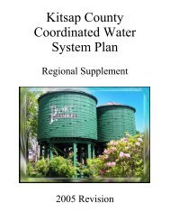
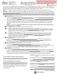
<strong>CENTRAL</strong> <strong>KITSAP</strong> <strong>COUNTY</strong><br />
<strong>WASTEWATER</strong> <strong>FACILITY</strong> <strong>PLAN</strong><br />
<strong>KITSAP</strong> <strong>COUNTY</strong><br />
PUBLIC WORKS<br />
<strong>WASTEWATER</strong> DIVISION<br />
Septage<br />
Receiving<br />
East<br />
Primary<br />
Clarifier<br />
Wes<br />
Prim<br />
Clar<br />
FRONTIER PL NW<br />
NW RANDALL WY<br />
<strong>KITSAP</strong> MALL BV NW<br />
Clear Clear Creek Creek<br />
MICKELBERRY RD NW<br />
atment<br />
P<br />
East<br />
igester<br />
Centrifuge<br />
P<br />
West<br />
Digester<br />
Grit<br />
Classifier<br />
Secondary Treatment<br />
Sludge<br />
Degritting<br />
East Aeration<br />
Aeration<br />
Basin<br />
Aeration<br />
Basin<br />
RAS<br />
RAS<br />
Mixing<br />
Boxes<br />
RAS<br />
Aeratio<br />
Basin<br />
Aeratio<br />
Basin<br />
NG SIDE DR NW<br />
STATE HY 3 NW<br />
SILVERDALE LOOP RD NW<br />
NW LOWELL ST<br />
MARTIN AV NW<br />
ERIE AV NW<br />
DAHL RD NW<br />
SILVERDALE WY NW<br />
BAY SHORE DR NW<br />
POPLARS AV NW<br />
NW BUCKLIN HILL RD<br />
BLAINE AV NW<br />
LEVIN RD NW<br />
SILVERDALE<br />
RIDGETOP BV NW<br />
NW MYHRE RD<br />
FREDRICKSON RD NW<br />
RICHARDSON RD NW<br />
CLIPPER PL NW<br />
MONTE VISTA DR NW<br />
OLSON RD NW<br />
NW SAENZ LN<br />
NW SELBO RD<br />
Secondary<br />
Influent<br />
P<br />
P<br />
E<br />
W<br />
JANE LINDSEY<br />
Consulting<br />
October 2009
TABLE OF CONTENTS<br />
LIST OF ABBREVIATIONS<br />
EXECUTIVE SUMMARY<br />
ES-1<br />
ES-2<br />
ES-3<br />
ES-4<br />
ES-5<br />
ES-6<br />
Introduction................................................................................................................................................ES-1<br />
Factors that Influence Wastewater Facility Design ....................................................................................ES-4<br />
ES-2.1 Planning Area Characteristics and Population Projections...........................................................ES-4<br />
ES-2.2 Wastewater Characteristics ..........................................................................................................ES-5<br />
ES-2.3 Existing Wastewater System Condition ........................................................................................ES-5<br />
ES-2.4 NPDES Permit and Other Regulations .........................................................................................ES-5<br />
Facilities Design and Evaluation Criteria and Methodology.......................................................................ES-6<br />
Wastewater System Project Recommendations........................................................................................ES-6<br />
ES-4.1 Collection System Improvements .................................................................................................ES-6<br />
ES-4.2 Treatment System Improvements.................................................................................................ES-7<br />
ES-4.3 Total Recommended Project Costs ..............................................................................................ES-8<br />
Financing Evaluation ...............................................................................................................................ES-11<br />
Recommended Wastewater System Capital Improvements....................................................................ES-11<br />
CHAPTER 1: INTRODUCTION<br />
1.1 Background and Purpose .............................................................................................................................1-1<br />
1.2 General Planning Area Definition..................................................................................................................1-2<br />
1.3 Description of Scope of Work .......................................................................................................................1-2<br />
1.4 Overview of the Facility Plan ........................................................................................................................1-3<br />
CHAPTER 2: <strong>PLAN</strong>NING AREA CHARACTERISTICS<br />
2.1 Overview of Chapter Contents......................................................................................................................2-1<br />
2.2 Urban Growth Areas .....................................................................................................................................2-1<br />
2.3 Planning and Service Areas .........................................................................................................................2-2<br />
2.3.1 Countywide Service Area....................................................................................................................2-3<br />
2.3.2 Northern Service Area ........................................................................................................................2-3<br />
2.3.3 Southern Service Area........................................................................................................................2-3<br />
2.4 Natural Systems Affecting Wastewater Collection and Treatment Systems and<br />
Reclaimed Water Opportunities....................................................................................................................2-4<br />
2.5 Population Estimates and Projections ..........................................................................................................2-5<br />
2.6 Land Use and Zoning ...................................................................................................................................2-6<br />
2.7 Equivalent Residential Unit Criteria ..............................................................................................................2-6<br />
2.8 Sewered Equivalent Population Projections .................................................................................................2-7<br />
1<br />
DRAFT for review purposes only.<br />
Use of contents on this sheet is subject to the limitations specified at the end of this document.<br />
P:\132857 Kitsap WW Facility Plan Ph II\600 Facility Plan\Revision 3 Draft Final Facility Plan\Table of Contents.doc
Table of Contents<br />
Central Kitsap County Wastewater Facility Plan<br />
CHAPTER 3: <strong>WASTEWATER</strong> CHARACTERISTICS<br />
3.1 Overview of Chapter Contents......................................................................................................................3-1<br />
3.2 Wastewater Flows ........................................................................................................................................3-1<br />
3.2.1 Wastewater Flow Parameters.............................................................................................................3-2<br />
3.2.2 Historical and Existing Flows ..............................................................................................................3-3<br />
3.2.3 Wastewater Flow Projections..............................................................................................................3-9<br />
3.3 Wastewater Composition and Loadings .....................................................................................................3-13<br />
3.3.1 Wastewater Loading Parameters......................................................................................................3-13<br />
3.3.2 Wastewater Loadings Projection ......................................................................................................3-13<br />
CHAPTER 4: DESCRIPTION AND CONDITION OF EXISTING <strong>WASTEWATER</strong> SYSTEM<br />
4.1 Overview of Chapter Contents......................................................................................................................4-1<br />
4.2 Existing Collection Facilities .........................................................................................................................4-1<br />
4.2.1 Flow Routing.......................................................................................................................................4-2<br />
4.2.2 Collection System Piping ....................................................................................................................4-5<br />
4.2.3 Lift Stations .........................................................................................................................................4-5<br />
4.3 Existing Wastewater Treatment Plant...........................................................................................................4-7<br />
4.3.1 Location ..............................................................................................................................................4-8<br />
4.3.2 Treatment Processes..........................................................................................................................4-8<br />
4.3.3 Unit Process Summary .....................................................................................................................4-15<br />
4.3.4 Overall Plant Assessment and Trigger Points for Expansion............................................................4-25<br />
4.4 Outfall and Diffuser .....................................................................................................................................4-28<br />
CHAPTER 5: NPDES PERMIT AND OTHER REGULATIONS<br />
5.1 Overview of Chapter Contents......................................................................................................................5-1<br />
5.2 NPDES Permit ..............................................................................................................................................5-1<br />
5.3 Other Federal, State, Regional, and Local Permits and Regulations............................................................5-3<br />
CHAPTER 6: FACILITIES DESIGN AND EVALUATION CRITERIA AND METHODOLOGIES<br />
6.1 Overview of Chapter Contents......................................................................................................................6-1<br />
6.2 Key Criteria and Methodologies Used to Identify, Evaluate, and Rank Projects...........................................6-1<br />
6.3 Collection System Projects ...........................................................................................................................6-5<br />
6.3.1 Project Identification ...........................................................................................................................6-5<br />
6.3.2 Project Evaluation...............................................................................................................................6-5<br />
6.3.3 Project Ranking ..................................................................................................................................6-6<br />
6.4 Treatment System Projects ..........................................................................................................................6-7<br />
6.4.1 Project Identification ...........................................................................................................................6-7<br />
6.4.2 Project Evaluation...............................................................................................................................6-7<br />
6.4.3 Project Ranking ................................................................................................................................6-13<br />
2<br />
DRAFT for review purposes only.<br />
Use of contents on this sheet is subject to the limitations specified at the end of this document.<br />
P:\132857 Kitsap WW Facility Plan Ph II\600 Facility Plan\Revision 3 Draft Final Facility Plan\Table of Contents.doc
Central Kitsap County Wastewater Facility Plan<br />
Table of Contents<br />
CHAPTER 7: COLLECTION SYSTEM IMPROVEMENTS<br />
7.1 Overview of Chapter Contents......................................................................................................................7-1<br />
7.2 Project Identification .....................................................................................................................................7-1<br />
7.2.1 Existing Lift Station Projects ...............................................................................................................7-2<br />
7.2.2 Existing Piping System Projects .........................................................................................................7-2<br />
7.2.3 Future Lift Station Projects in UGA.....................................................................................................7-6<br />
7.2.4 Future Piping System Projects in UGA ...............................................................................................7-6<br />
7.3 Project Evaluation.........................................................................................................................................7-7<br />
7.3.1 Existing Lift Station Projects ...............................................................................................................7-7<br />
7.3.2 Existing Piping System Projects .........................................................................................................7-8<br />
7.3.3 Future Lift Station Projects in UGA.....................................................................................................7-9<br />
7.3.4 Future Piping System Projects in UGA ...............................................................................................7-9<br />
7.4 Project Ranking .........................................................................................................................................7-10<br />
7.4.1 Existing Lift Station Projects .............................................................................................................7-11<br />
7.4.2 Existing Piping System Projects .......................................................................................................7-12<br />
7.5 Timeline for Collection System Projects .....................................................................................................7-13<br />
7.5.1 Project Implementation Assumptions................................................................................................7-14<br />
7.5.2 Capital Improvement Program..........................................................................................................7-14<br />
CHAPTER 8: <strong>WASTEWATER</strong> TREATMENT IMPROVEMENTS, REUSE OPTIONS, AND ENERGY<br />
CONSERVATION AND GENERATION OPPORTUNITIES<br />
8.1 Overview of Chapter Contents......................................................................................................................8-1<br />
8.2 Project Identification .....................................................................................................................................8-2<br />
8.3 Project Evaluation.......................................................................................................................................8-10<br />
8.3.1 Initial Evaluation................................................................................................................................8-10<br />
8.3.2 Final Evaluation ................................................................................................................................8-24<br />
8.3.3 Combined Wastewater Treatment and Reuse Alternatives ...............................................................8-30<br />
8.4 Project Ranking ..........................................................................................................................................8-39<br />
8.5 Project Recommendations..........................................................................................................................8-40<br />
8.6 Project Costs ..............................................................................................................................................8-41<br />
CHAPTER 9: FINANCING EVALUATION<br />
9.1 Overview of Chapter Contents......................................................................................................................9-1<br />
9.2 Capital Improvement Alternatives.................................................................................................................9-1<br />
9.3 Projected Revenue Requirement..................................................................................................................9-5<br />
9.4 Projected Revenue Increases Required from Rates.....................................................................................9-5<br />
9.5 Conclusions ................................................................................................................................................9-11<br />
3<br />
DRAFT for review purposes only.<br />
Use of contents on this sheet is subject to the limitations specified at the end of this document.<br />
P:\132857 Kitsap WW Facility Plan Ph II\600 Facility Plan\Revision 3 Draft Final Facility Plan\Table of Contents.doc
Table of Contents<br />
Central Kitsap County Wastewater Facility Plan<br />
APPENDICES<br />
1. Glossary of Terms<br />
2A. Natural Systems<br />
Appendix Figure 2A-1. Topography and drainage<br />
Appendix Figure 2A-2. Potential reuse investigation sites<br />
Appendix Figure 2A-3. Drinking water wells<br />
Appendix Figure 2A-4. Preliminary water quality issues<br />
Appendix Figure 2A-5. Geohazards<br />
Appendix Figure 2A-6. Sensitive habitat<br />
2B. Geology, Groundwater, and Soils Characterization<br />
2C. Technical memorandum (June 23, 2006) from BHC Consultants to Kitsap County Department of Public<br />
Works re: Central Kitsap County Wastewater Facilities Development Strategy Plan Preliminary Water<br />
Quality Issues<br />
2D. Technical memorandum (August 23, 2006) from Brown and Caldwell to Kitsap County Department of Public<br />
Works re: Central Kitsap County Wastewater Facilities Development Strategy Plan: Water Reuse<br />
3A. Technical memorandum (August 1, 2008) from BHC Consultants to Kitsap County Department of Public<br />
Works re: Central Kitsap Wastewater Facilities Plan Wastewater Flow Projections 2005–2025<br />
3B. ASCE peaking factor curves (excerpt, Design and Construction of Sanitary and Storm Sewers,<br />
ASCE/WPCF, 1969)<br />
3C. Wastewater Composition and Loadings<br />
4A. NPDES Permit No. WA-003052-0 (effective June 1, 2007)<br />
4B. NPDES Permit No. WA-003052-0 Fact Sheet<br />
4C. Technical memorandum (November 3, 2008) from Brown and Caldwell to Kitsap County Department of<br />
Public Works re: Central Kitsap County Wastewater Facility Plan Existing Treatment Plant Capacity<br />
Evaluation<br />
4D. Projected Flows for the Central Kitsap WWTP Service Area: Estimation of Time Frame for Plant Flows to<br />
Reach 85 Percent Design Capacity for 3 Consecutive Months Using Compound Growth Rates<br />
5. Other Federal, State, Regional, and Local Permits and Regulations<br />
6A. Cost Criteria<br />
6B. Central Kitsap WW Facility Plan Alternative Initial Evaluation Criteria<br />
6C. CKWWTP Facility Plan Final Evaluation Criteria for Process Selection<br />
7A. Conveyance System Model Description<br />
7B. Basis for Construction Costs:<br />
a. Conveyance system pipelines<br />
b. Lift stations<br />
c. Associated project costs<br />
7C. Example of Conveyance System Analysis: Problem Areas A, 4, and 6:<br />
a. Schematic of plan of study area<br />
b. Lift station #1 inflow hydrographs for 2005 and 2025 flows<br />
c. Hydraulic profiles for existing system using 2005 and 2025 flows for problem identification<br />
d. Hydraulic profile of existing system with improvements using 2025 flows<br />
4<br />
DRAFT for review purposes only.<br />
Use of contents on this sheet is subject to the limitations specified at the end of this document.<br />
P:\132857 Kitsap WW Facility Plan Ph II\600 Facility Plan\Revision 3 Draft Final Facility Plan\Table of Contents.doc
Central Kitsap County Wastewater Facility Plan<br />
Table of Contents<br />
e. Listing of specific improvements<br />
f. Construction cost estimates of improvements<br />
7D. Lemolo Siphon and Lift Station 16 Analyses<br />
7E. Memorandum (July 14, 2009) from BHC Consultants to Kitsap County Department of Public Works re:<br />
Kitsap County South Central Force Main Project—Potential Transient Pressures in the Schedule 1<br />
Force Main<br />
8A. PowerPoint presentation (October 28, 2008): Central Kitsap County Wastewater Treatment Plant<br />
Alternatives Development Workshop<br />
8B. WWTP process element descriptions<br />
8C. Technical memorandum (May 27, 2009) from Brown and Caldwell to Kitsap County Department of Public<br />
Works re: Satellite Treatment Facility Alternatives Evaluation<br />
8D. Technical memorandum (June 20, 2007) from Brown and Caldwell to Kitsap County Department of Public<br />
Works re: Anaerobic Digestion and Thickening Process Selection<br />
8E. Technical memorandum (May 28, 2009) from Brown and Caldwell to Kitsap County Department of Public<br />
Works re: Digestion and Thickening Process Analysis<br />
8F. Technical memorandum (May 28, 2009) from Brown and Caldwell to Kitsap County Department of Public<br />
Works re: Supplementary Energy and Solids Process Calculations<br />
8G. Draft Technical memorandum (April 30, 2008) from Brown and Caldwell to Kitsap County Department of<br />
Public Works re: Required Upgrades for the Central Kitsap Wastewater Treatment Plant<br />
8H. Technical memorandum (May 21, 2007) from Brown and Caldwell to Kitsap County Department of Public<br />
Works re: Class A Biosolids Survey<br />
8I. Technical memorandum (May 28, 2009) from Brown and Caldwell to Kitsap County Department of Public<br />
Works re: Class A Biosolids Process Screening<br />
8J. Technical memorandum (June 22, 2007) from Brown and Caldwell to Kitsap County Department of Public<br />
Works re: Central Kitsap Wastewater Treatment Plant Phase III Upgrade Sludge Dryer Cost Analysis<br />
8K. Technical memorandum: planning-level evaluation of alternatives for management of biosolids produced at<br />
the CKWWTP and other wastewater treatment plants<br />
8L. CKWWTP Cost Estimates<br />
8M. Central Kitsap WW Facility Plan Treatment Alternative Evaluation Matrix<br />
5<br />
DRAFT for review purposes only.<br />
Use of contents on this sheet is subject to the limitations specified at the end of this document.<br />
P:\132857 Kitsap WW Facility Plan Ph II\600 Facility Plan\Revision 3 Draft Final Facility Plan\Table of Contents.doc
Table of Contents<br />
Central Kitsap County Wastewater Facility Plan<br />
LIST OF TABLES<br />
ES-1<br />
ES-2<br />
ES-3<br />
ES-4<br />
ES-5<br />
ES-6<br />
Key Criteria Used to Select Projects..........................................................................................................ES-3<br />
Equivalent Sewered Population for CKWWTP Service Area and Poulsbo ................................................ES-4<br />
Projected Flows and Loadings at CKWWTP .............................................................................................ES-5<br />
Summary of Total Collection System Improvements, Construction, and Project Costs.............................ES-6<br />
Summary of Recommended Facilities for CKWWTP.................................................................................ES-7<br />
Summary of Total Infrastructure Improvement Project Costs ....................................................................ES-8<br />
1-1 Key Criteria Affecting Wastewater Capital Projects ......................................................................................1-2<br />
1-2 Organization of the Central Kitsap County Wastewater Facility Plan ...........................................................1-3<br />
2-1 Wastewater Service Responsibilities by Service Area..................................................................................2-2<br />
2-2 Natural System Characteristics and Their Effects on Wastewater Management Infrastructure....................2-4<br />
2-3 Population Projections for CKWWTP Service Area and Poulsbo .................................................................2-5<br />
2-4 ERU Projections for CKWWTP Service Area and Poulsbo...........................................................................2-7<br />
3-1 Applications of Wastewater Flow Parameters ..............................................................................................3-2<br />
3-2 2006–2007 Flow Meters for the CKWWTP Service Area .............................................................................3-4<br />
3-3 Summary of Central Kitsap Wastewater Flows from 2002 to 2006 for the CKWWTP Service Area.............3-6<br />
3-4 Per Capita Wastewater Flows for the Southern Service Area ....................................................................3-10<br />
3-5 Composite Hydraulic Peaking Factors for Year 2025 Flow Projections at the CKWWTP...........................3-11<br />
3-6 Summary of Projected Wastewater Flows. .................................................................................................3-12<br />
3-7 Projected Flows and Loadings at CKWWTP ..............................................................................................3-14<br />
4-1 Summary of Existing Collection System Piping ............................................................................................4-5<br />
4-2 Existing Lift Stations .....................................................................................................................................4-6<br />
4-3 CKWWTP Existing Process Design Data .....................................................................................................4-9<br />
4-4 CKWWTP NPDES Requirements...............................................................................................................4-10<br />
4-5 CKWWTP Average Effluent Fecal Coliform, Ammonia, and Metals Concentrations, 2004– 2006 .............4-14<br />
4-6 CKWWTP Estimated Plant Remaining Capacity ........................................................................................4-26<br />
4-7 CKWWTP Unit Process Projected Expansion Timing.................................................................................4-28<br />
6-1 Key Criteria Used to Identify, Evaluate, and Rank Projects..........................................................................6-1<br />
6-2 Summary of Initial Treatment Unit Process Evaluation Criteria ....................................................................6-9<br />
6-3 Treatment Alternatives Final Evaluation Matrix ..........................................................................................6-11<br />
7-1 Summary of Projects for Existing Collection System Piping Improvements for Existing Flows ....................7-3<br />
7-2 Projects for Existing Collection System Piping Improvements for Future Flows...........................................7-5<br />
7-3 Existing Lift Station Projects .........................................................................................................................7-7<br />
7-4 Summary of Future Lift Station Costs...........................................................................................................7-9<br />
7-5 Summary of Improvements, Construction and Project Costs: Future UGA Collection System Piping........7-10<br />
7-6 Summary of Total Collection System Improvements, Construction, and Project Costs..............................7-10<br />
6<br />
DRAFT for review purposes only.<br />
Use of contents on this sheet is subject to the limitations specified at the end of this document.<br />
P:\132857 Kitsap WW Facility Plan Ph II\600 Facility Plan\Revision 3 Draft Final Facility Plan\Table of Contents.doc
Central Kitsap County Wastewater Facility Plan<br />
Table of Contents<br />
8-1 Identification of Liquid Stream Alternatives...................................................................................................8-2<br />
8-2 Identification of Solids Stream Alternatives...................................................................................................8-6<br />
8-3 Identification of Side Stream Alternatives .....................................................................................................8-9<br />
8-4 Screening of Liquid Stream Alternatives.....................................................................................................8-11<br />
8-5 Screening of Solids Stream Alternatives.....................................................................................................8-17<br />
8-6 Screening of Side Stream Alternatives .......................................................................................................8-21<br />
8-7 Summary of Selected Liquid Stream, Solids Stream, and Side Stream Treatment Technologies<br />
for Final Evaluation .....................................................................................................................................8-23<br />
8-8 Reclaimed Water Quality Criteria Selected for the Facility Plan .................................................................8-24<br />
8-9 Summary of Biogas Use Alternatives for CKWWTP...................................................................................8-27<br />
8-10 Summary of Ancillary Processes for Nutrient Recovery, Biogas Generation, and Solids Reductions ........8-27<br />
8-11 CKWWTP Liquid Stream Treatment Alternatives .......................................................................................8-30<br />
8-12 CKWWTP Liquid Stream Treatment Alternatives Sizing and Cost Summary.............................................8-37<br />
8-13 Evaluation Summary of CKWWTP Liquid Stream Treatment Alternatives .................................................8-38<br />
8-14 CKWWTP Liquid Stream Treatment Alternatives Ranking .........................................................................8-39<br />
8-15 Summary of Recommended Facilities for CKWWTP..................................................................................8-40<br />
8-16 Summary of Total Infrastructure Improvement Project Costs .....................................................................8-41<br />
9-1 Alternative 1 CIP Financing Plan: No Reuse (Secondary Treatment Only) ..................................................9-3<br />
9-2 Alternative 2 CIP Financing Plan: Partial Reuse (3.5 mgd) ..........................................................................9-3<br />
9-3 Alternative 3 CIP Financing Plan: Full Reuse ...............................................................................................9-4<br />
9-4 Alternative 1 Annual Revenue Requirement: No Reuse (Secondary Treatment Only).................................9-7<br />
9-5 Alternative 2 Annual Revenue Requirement: Partial Reuse (3.5 mgd) .........................................................9-8<br />
9-6 Alternative 3 Annual Revenue Requirement: Full Reuse..............................................................................9-9<br />
9-7 Ecology Financial Hardship Evaluation.......................................................................................................9-12<br />
7<br />
DRAFT for review purposes only.<br />
Use of contents on this sheet is subject to the limitations specified at the end of this document.<br />
P:\132857 Kitsap WW Facility Plan Ph II\600 Facility Plan\Revision 3 Draft Final Facility Plan\Table of Contents.doc
Table of Contents<br />
Central Kitsap County Wastewater Facility Plan<br />
LIST OF FIGURES<br />
ES-1<br />
ES-2<br />
ES-3<br />
ES-4<br />
ES-5<br />
ES-6<br />
Facility planning methodology....................................................................................................................ES-2<br />
Central Kitsap planning areas (vicinity map)..................................................................................follows ES-4<br />
Total Central Kitsap wastewater facilities capital expenditures with no reuse ...........................................ES-9<br />
Total Central Kitsap wastewater facilities capital expenditures with partial reuse....................................ES-10<br />
Total Central Kitsap wastewater facilities capital expenditures with full reuse.........................................ES-11<br />
Annual rate impact summary ...................................................................................................................ES-12<br />
1-1 Central Kitsap County planning areas ............................................................................................. follows 1-2<br />
2-1 Service areas and local treatment plants..........................................................................................follows 2-2<br />
2-2 2006 land use ...................................................................................................................................follows 2-2<br />
2-3 Zoning designations map..................................................................................................................follows 2-6<br />
2-4 Sewered and unsewered developed properties................................................................................follows 2-7<br />
3-1 Collection and conveyance system flow measurement locations .....................................................follows 3-4<br />
3-2 Daily southern flow patterns for estimation of infiltration and inflow................................................follows 3-10<br />
3-3 Projected ADFs at the CKWWTP ...............................................................................................................3-12<br />
4-1 Southern Service Area key map .......................................................................................................follows 4-2<br />
4-2 Existing collection system schematic................................................................................................follows 4-2<br />
4-3 Central Kitsap east existing sewer basins ........................................................................................follows 4-2<br />
4-4 Central Kitsap west existing sewer basins........................................................................................follows 4-2<br />
4-5 Silverdale north existing sewer basins..............................................................................................follows 4-2<br />
4-6 Silverdale south existing sewer basins .............................................................................................follows 4-2<br />
4-7 Existing CKWWTP process flow schematic......................................................................................follows 4-8<br />
4-8 CKWWTP effluent quality and overall pollutant removals, 2004–2006.......................................................4-13<br />
4-9 CKWWTP monthly biosolids production rates, 2004–2006 ........................................................................4-15<br />
4-10 Trigger point for hydraulic treatment capacity expansion at the CKWWTP based on the<br />
current plant capacity rating........................................................................................................................4-27<br />
6-1 Facility planning methodology.......................................................................................................................6-4<br />
7-1 Existing lift station capacity and existing peak flows........................................................................ follows 7-2<br />
7-2 Existing lift station capacity and future 2025 peak flows...................................................................follows 7-2<br />
7-3 Silverdale existing problem areas.....................................................................................................follows 7-2<br />
7-4 Central Kitsap existing problem areas ..............................................................................................follows 7-2<br />
7-5 Silverdale – South future problem areas...........................................................................................follows 7-6<br />
7-6 Silverdale – North future problem areas ...........................................................................................follows 7-6<br />
7-7 Central Kitsap – East future problem areas ......................................................................................follows 7-6<br />
7-8 Central Kitsap – West future problem areas .....................................................................................follows 7-6<br />
7-9 New future lift station capacity requirements for 2025 flows.............................................................follows 7-6<br />
7-10 Silverdale – South new future sewer system ....................................................................................follows 7-6<br />
7-11 Silverdale – North new future sewer system.....................................................................................follows 7-6<br />
8<br />
DRAFT for review purposes only.<br />
Use of contents on this sheet is subject to the limitations specified at the end of this document.<br />
P:\132857 Kitsap WW Facility Plan Ph II\600 Facility Plan\Revision 3 Draft Final Facility Plan\Table of Contents.doc
Central Kitsap County Wastewater Facility Plan<br />
Table of Contents<br />
7-12 Central Kitsap – East new future sewer system ...............................................................................follows 7-6<br />
7-13 Central Kitsap – West new future sewer system ..............................................................................follows 7-6<br />
7-14 Central Kitsap conveyance facilities capital expenditures allocated to the County.....................................7-14<br />
8-1 Process flow diagram for Alternative 1 (CAS with summer nitrification) .....................................................8-34<br />
8-2 Process flow diagram for Alternative 2 (CAS with year-round nitrification).................................................8-34<br />
8-3 Process flow diagram for Alternative 3 (CAS with side stream MBR).........................................................8-34<br />
8-4 Process flow diagram for Alternative 4 (full MBR conversion with TN removal) .........................................8-35<br />
8-5 Process flow diagram for Alternative 5 (CAS with TN removal and partial flow effluent filtration) ..............8-35<br />
8-6 Process flow diagram for Alternative 6 (CAS with TN removal and full flow effluent filtration)....................8-35<br />
8-7 Process flow diagram for Alternative 7 (IFAS with TN removal and partial flow effluent filtration)..............8-36<br />
8-8 Process flow diagram for Alternative 8 (IFAS with TN removal and full flow effluent filtration) ...................8-36<br />
8-9 Total Central Kitsap wastewater facilities capital expenditures with no reuse ............................................8-42<br />
8-10 Total Central Kitsap wastewater facilities capital expenditures with partial reuse.......................................8-43<br />
8-11 Total Central Kitsap wastewater facilities capital expenditures with full reuse............................................8-43<br />
9-1 Annual rate impact summary ......................................................................................................................9-11<br />
9<br />
DRAFT for review purposes only.<br />
Use of contents on this sheet is subject to the limitations specified at the end of this document.<br />
P:\132857 Kitsap WW Facility Plan Ph II\600 Facility Plan\Revision 3 Draft Final Facility Plan\Table of Contents.doc
LIST OF ABBREVIATIONS<br />
µg/L: micrograms/liter<br />
10-Year Update: Kitsap County Comprehensive Land Use Plan<br />
10-Year Update (2006)<br />
401 Certification: Section 401 Water Quality Certification<br />
AAF: average annual flow<br />
AB: aeration basin<br />
ACEC: acute critical effluent concentration<br />
ADF: average design flow<br />
ADWF: average dry weather flow<br />
AS: aeration station<br />
ASCE: American Society of Civil Engineers<br />
ASL: above sea level<br />
ATAD: autothermal thermophilic aerobic digestion<br />
AWWF: average wet weather flow<br />
BABE: bioaugmentation batch enhanced (process)<br />
BAF: biological aerated filter<br />
BAR: bioaugmentation re-aeration (process)<br />
BOD5: biochemical oxygen demand<br />
BSL: below sea level<br />
CAHTS: Class A heat treatment system<br />
CAS: conventional activated sludge<br />
CBOD: carbonaceous biochemical oxygen demand<br />
Cd: cadmium<br />
CEC: compound of emerging concern<br />
Centennial: Centennial Clean Water Fund Program<br />
CEPT: chemically enhanced primary clarification<br />
CIP: Capital Improvement Program<br />
CKWWTP: Central Kitsap Wastewater Treatment Plant<br />
CNG: compressed natural gas<br />
COD: chemical oxygen demand<br />
Compliance Plan: Central Kitsap GMA Compliance Plan<br />
Corps: U.S. Army Corps of Engineers<br />
Cr: chromium<br />
Cu: copper<br />
cu ft: cubic foot/feet<br />
CWA: Clean Water Act<br />
d: day<br />
DAFT: dissolved air flotation thickener<br />
DAHP: Washington Department of Archaeology and Historic<br />
Preservation<br />
DCD: Kitsap County Department of Community Development<br />
DH+: Data Highway Plus<br />
DHI: Danish Hydraulic Institute<br />
DNR: Washington Department of Natural Resources<br />
DNS: determination of nonsignificance<br />
DO: dissolved oxygen<br />
EA: environmental assessment<br />
Ecology: Washington State Department of Ecology<br />
ECS: Engineered Compost Systems<br />
EIS: environmental impact statement<br />
ENR-CCI: Engineering News Record Construction Cost Index<br />
EPA: U.S. Environmental Protection Agency<br />
EQ: equalization (basin)<br />
ERU: equivalent residential unit<br />
ESA: Endangered Species Act<br />
Facility Plan: Central Kitsap County Wastewater Facility Plan<br />
(2009) (this document)<br />
FM: force main<br />
FONSI: Finding of No Significant Impact<br />
FPC: firm pumping capacity<br />
fps: foot/feet per second<br />
1<br />
DRAFT for review purposes only.<br />
Use of contents on this sheet is subject to the limitations specified at the end of this document.<br />
P:\132857 Kitsap WW Facility Plan Ph II\600 Facility Plan\Revision 3 Draft Final Facility Plan\List of Abbreviations.doc
List of Abbreviations<br />
Central Kitsap County Wastewater Facility Plan<br />
ft: foot/feet<br />
gal: gallons<br />
GBT: gravity belt thickener<br />
GHG: greenhouse gas<br />
GMA: Washington State Growth Management Act<br />
gpcd: gallons per capita per day<br />
gpd: gallons per day<br />
gpd/acre: gallons per day per acre<br />
gpm: gallons per minute<br />
GWMP: Groundwater Management Plan<br />
HDD: horizontal directional drilling<br />
Health District: Kitsap County Health District<br />
Hg: mercury<br />
HGL: hydraulic grade line<br />
HMI: human-machine interface<br />
hp: horsepower<br />
HPA: Hydraulic Project Approval<br />
HPO: high-purity oxygen<br />
HRT: hydraulic retention time<br />
HVAC: heating, ventilation, and air conditioning<br />
I/I: infiltration and inflow<br />
IFAS: integrated fixed-film activated sludge<br />
IMLR: internal mixed liquor recycle<br />
IO: input/output<br />
J&B: jack and bore<br />
JARPA: Joint Aquatic Resources Permit Application<br />
KCC: Kitsap County Code<br />
kPa: kilopascal<br />
kV: kilovolt<br />
kVA: kilovolt-ampere<br />
kW: kilowatt<br />
LAMIRD: limited area of more intense development<br />
lb: pound<br />
LF: linear feet<br />
LS: lift station<br />
MBBR: moving bed biofilm reactor<br />
MBR: membrane bioreactor<br />
MCC: motor control center<br />
MDF: maximum day flow<br />
MG: million gallons<br />
mgd: million gallons per day<br />
mg/L: milligrams per liter<br />
MH: manhole<br />
MHHW: mean higher high water<br />
MHI: median household income<br />
mL/g: milliliters per gram<br />
MLLW: mean lower low water<br />
MLSS: mixed liquor suspended solids<br />
MSL: mean sea level<br />
MTL: mean tide level<br />
NH3-N: ammonia-nitrogen<br />
MT: membrane tank<br />
NBOD: nitrogenous biological oxygen demand<br />
NEPA: National Environmental Policy Act<br />
Ni: nickel<br />
NOAA: National Oceanic and Atmospheric Administration<br />
NPDES: National Pollutant Discharge Elimination System<br />
NPV: net present value<br />
NTU: nephelometric turbidity unit<br />
O&M: operation and maintenance<br />
Operations: Kitsap County Public Works Operations<br />
Orange Book: Criteria for Sewage Works Design (Ecology, 2008)<br />
PAC: powdered activated carbon<br />
Pb: lead<br />
PDF: peak design flow<br />
PDWF: peak dry weather flow<br />
PHS: Priority Habitats and Species<br />
PIC: Pollution Identification and Correction<br />
2<br />
DRAFT for review purposes only.<br />
Use of contents on this sheet is subject to the limitations specified at the end of this document.<br />
P:\132857 Kitsap WW Facility Plan Ph II\600 Facility Plan\Revision 3 Draft Final Facility Plan\List of Abbreviations.doc
Central Kitsap County Wastewater Facility Plan<br />
List of Abbreviations<br />
PLC: programmable logic controller<br />
PMF: peak month flow<br />
POP: point-of-presence<br />
Poulsbo Sewer Plan: City of Poulsbo Draft Comprehensive<br />
Sanitary Sewer Plan 2007 Update<br />
ppd: pounds per day<br />
ppm: parts per million<br />
PSCAA: Puget Sound Clean Air Agency<br />
psi: pounds per square inch<br />
psig: pounds per square inch gauge<br />
PSRP: process that significantly reduces pathogens<br />
PUD: Kitsap County Public Utility District<br />
PWWF: peak wet weather flow<br />
RAS: return activated sludge<br />
RBC: rotating biological contactors<br />
RCW: Revised Code of Washington<br />
RDT: rotary drum thickener<br />
remote input/output (RIO)<br />
Reuse Standards: Washington State Water Reclamation and<br />
Reuse Standards (2007)<br />
RO: reverse osmosis<br />
SBR: sequencing batch reactor<br />
SCADA: supervisory control and data acquisition<br />
scfm: standard cubic feet per minute<br />
SDAP: Site Development Activity Permit<br />
SEPA: Washington State Environmental Policy Act<br />
SERP: State Environmental Review Process<br />
SMA: Shoreline Management Act<br />
SOC: Species of Concern<br />
SWD: State Waste Discharge<br />
SWGR: switchgear<br />
TDH: total dynamic head<br />
TDS: total dissolved solids<br />
TF/SC: trickling filter/solids contact<br />
TN: total nitrogen<br />
TPAD: temperature-phased anaerobic digestion<br />
tpd: tons per day<br />
TMDL: total maximum daily load<br />
TSS: total suspended solids<br />
UGA: Urban Growth Area<br />
ULCA: Updated Land Capacity Analysis (2006)<br />
USCS: U. S. Soil Conservation Service<br />
USFW: U.S. Fish and Wildlife Service<br />
USGS: U.S. Geological Survey<br />
UV: ultraviolet<br />
VFD: variable frequency drive<br />
VS: volatile solids<br />
VSS: volatile suspended solids<br />
WAC: Washington Administrative Code<br />
WAS: waste activated sludge<br />
Water Quality Memo: Central Kitsap County Wastewater Facilities<br />
Development Strategy Plan Preliminary Water Quality<br />
Issues (BHC, June 2006)<br />
WDFW: Washington Department of Fish and Wildlife<br />
WML: waste mixed liquor<br />
WRIA: water resource inventory area<br />
WWTP: wastewater treatment plant<br />
Zn: zinc<br />
sq ft: square foot/feet<br />
SR: State Route<br />
SRF: State Revolving Fund<br />
SRT: sludge retention time<br />
SVI: sludge volume index<br />
SWBD: switchboard<br />
3<br />
DRAFT for review purposes only.<br />
Use of contents on this sheet is subject to the limitations specified at the end of this document.<br />
P:\132857 Kitsap WW Facility Plan Ph II\600 Facility Plan\Revision 3 Draft Final Facility Plan\List of Abbreviations.doc
EXECUTIVE SUMMARY<br />
ES-1<br />
Introduction<br />
Planning the 20-year wastewater infrastructure needs of a fast-growing region presents enormous challenges.<br />
Expanding populations must be served and increasing flows must be handled. Infrastructure must be used<br />
wisely to maximize limited resources; regulations must be followed. Planning on this level involves weighing a<br />
complicated array of interconnected—and often conflicting—factors and variables.<br />
But challenges also reveal opportunities. Exciting technologies are now available that promote water<br />
reclamation, energy efficiency, and overall environmental sustainability as never before. A window is open to<br />
extraordinary possibilities. This Central Kitsap County Wastewater Facility Plan (Facility Plan) provides a road map<br />
for the Central Kitsap area’s long-term wastewater infrastructure needs. It also explores system improvements<br />
that would start moving Kitsap County toward a greener future.<br />
The overall goal of providing sewerage service is to protect public health and the quality of water resources.<br />
This Facility Plan identifies the facilities required to meet these goals and provides guidance for the<br />
development of wastewater facilities for a growing service area. Beyond that, it highlights opportunities for<br />
Kitsap County to chart a more sustainable, energy-efficient course. It also must comply with Washington<br />
Department of Ecology (Ecology) regulations for facilities plans (WAC 173-240-060). This Facility Plan will<br />
allow the County to manage growth within the context of a countywide wastewater service network.<br />
To develop a 20-year wastewater facility plan, a comprehensive, defensible decision-making methodology first<br />
must be established. The recommendations provided in this Facility Plan were arrived at by determining a set<br />
of key criteria. These criteria are based on the following factors:<br />
• planning area characteristics and population projections<br />
• estimated wastewater flows and loadings<br />
• condition of existing infrastructure<br />
• current regulations.<br />
The key criteria were then applied to all potential wastewater infrastructure project alternatives to identify,<br />
evaluate, and rank them. Only capital projects that can be easily supplemented or modified for future<br />
wastewater reclamation and reuse have been identified for consideration. (Note: The term “reuse” is used<br />
broadly in this Facility Plan to express any efforts to increase the wastewater system’s beneficial use of<br />
biosolids, energy efficiency, water reclamation, and overall environmental sustainability.) Figure ES-1 provides<br />
a general graphical depiction of the methodology that was employed to reach the final recommendations.<br />
ES-1<br />
DRAFT for review purposes only.<br />
Use of contents on this sheet is subject to the limitations specified at the end of this document.<br />
P:\132857 Kitsap WW Facility Plan Ph II\600 Facility Plan\Revision 3 Draft Final Facility Plan\Executive Summary\Executive Summary(BP).doc
Executive Summary<br />
Central Kitsap County Wastewater Facility Plan<br />
Figure ES-1. Facility planning methodology<br />
ES-2<br />
DRAFT for review purposes only.<br />
Use of contents on this sheet is subject to the limitations specified at the end of this document.<br />
P:\132857 Kitsap WW Facility Plan Ph II\600 Facility Plan\Revision 3 Draft Final Facility Plan\Executive Summary\Executive Summary(BP).doc
Central Kitsap County Wastewater Facility Plan<br />
Executive Summary<br />
The criteria that most heavily influence the selection of potential projects for further consideration are shown<br />
in Table ES-1. This table also indicates which of the two main wastewater infrastructure categories these<br />
criteria apply to.<br />
Table ES-1. Key Criteria Used to Select Projects<br />
Key<br />
criterion<br />
number<br />
Key criterion<br />
1 Correct known<br />
wastewater system<br />
deficiencies<br />
2 Repair and replace<br />
aged assets<br />
3 Provide wastewater<br />
service capacity for<br />
planning period<br />
growth (serving<br />
wastewater flow and<br />
load projections)<br />
4 Regulatory<br />
compliance<br />
Key criterion attributes<br />
Facilities are intended to rectify known<br />
existing significant wastewater<br />
infrastructure deficiencies.<br />
Facilities are intended to repair and<br />
replace wastewater system components<br />
that are near or beyond asset service<br />
life.<br />
Facilities provide capacity expansion to<br />
meet wastewater service requirements<br />
for anticipated growth in the planning<br />
period (to year 2025), consistent with<br />
GMA requirements.<br />
Facilities must comply with all applicable<br />
regulations and permits.<br />
5 Land use Facilities are intended to provide service<br />
for applicable designated land use<br />
categories, and to avoid sensitive areas<br />
unsuitable for service or for wastewater<br />
facilities. Use and upgrade of existing<br />
infrastructure is encouraged.<br />
6 Accepted engineering<br />
design criteria<br />
7 Best available<br />
technologies<br />
8 System operational<br />
considerations<br />
9 Flexibility for future<br />
expansion<br />
10 Reclaimed water<br />
utilization<br />
Facilities must comply with Ecology and<br />
other accepted industry standards for<br />
design and operations.<br />
Facilities utilize the currently available<br />
best technology to meet existing and<br />
anticipated wastewater system needs<br />
economically, efficiently, and reliably.<br />
Capital improvements facilitate<br />
maintenance and operations of facilities.<br />
Facilities can be modified or expanded<br />
to provide new roles or services without<br />
creating stranded investments or<br />
precluding future opportunities.<br />
Facilities enable the beneficial use of<br />
highly treated wastewater effluent for<br />
irrigation, groundwater recharge, and<br />
stream flow augmentation. All<br />
wastewater effluent is currently<br />
discharged to Puget Sound.<br />
11 Energy usage Treatment processes or facilities are<br />
capable of reducing energy consumption<br />
or of producing “green power.”<br />
Applicable to<br />
collection<br />
system<br />
projects<br />
<br />
<br />
<br />
<br />
<br />
<br />
Applicable to<br />
treatment<br />
system<br />
projects<br />
<br />
<br />
<br />
<br />
<br />
<br />
<br />
<br />
Facility Plan<br />
chapters where<br />
discussed<br />
4, 7<br />
4<br />
3<br />
4, 5<br />
2, 7, 8<br />
6, 7, 8<br />
7, 8<br />
8<br />
8<br />
8<br />
<br />
8<br />
ES-3<br />
DRAFT for review purposes only.<br />
Use of contents on this sheet is subject to the limitations specified at the end of this document.<br />
P:\132857 Kitsap WW Facility Plan Ph II\600 Facility Plan\Revision 3 Draft Final Facility Plan\Executive Summary\Executive Summary(BP).doc
Executive Summary<br />
Central Kitsap County Wastewater Facility Plan<br />
Table ES-1. Key Criteria Used to Select Projects<br />
Key<br />
criterion<br />
number<br />
Key criterion<br />
Key criterion attributes<br />
12 Biosolids utilization Facilities continue or enhance the use of<br />
biosolids and nutrient recycling.<br />
Currently, biosolids from the CKWWTP<br />
are conveyed to a private enterprise for<br />
a beneficial reuse of this product.<br />
13 Environmental and<br />
sensitive area<br />
concerns<br />
14 Community<br />
considerations<br />
Facilities minimize environmental<br />
impacts for water quality, biosolids<br />
quality, noise, odor, and wildlife habitat<br />
in the surrounding community and in<br />
sensitive areas in particular.<br />
Facilities are consistent with Kitsap<br />
County policies and are least disruptive<br />
to community values, aesthetics, and<br />
safety.<br />
15 Planning-level costs Facilities provide the maximum value for<br />
the least cost. In the case of collection<br />
system improvements, total project cost<br />
(capital cost) is used as the key cost<br />
criterion. For treatment system<br />
improvements, net present value (NPV)<br />
is used as the key cost criterion for<br />
alternatives evaluation. Planning-level<br />
cost accuracy typically ranges from +50<br />
to -30 percent.<br />
Applicable to<br />
collection<br />
system<br />
projects<br />
<br />
<br />
<br />
Applicable to<br />
treatment<br />
system<br />
projects<br />
Facility Plan<br />
chapters where<br />
discussed<br />
8<br />
<br />
<br />
<br />
2, 7, 8<br />
7, 8<br />
6, 7, 8, 9<br />
ES-2<br />
Factors that Influence Wastewater Facility Design<br />
This section summarizes the factors that determine which design alternatives are considered for a wastewater<br />
system. These factors are all discussed in greater detail in the main body of this Facility Plan.<br />
ES-2.1<br />
Planning Area Characteristics and Population Projections<br />
Central Kitsap County’s physical characteristics, population projections, and subsequent land use priorities<br />
play a critical role in selecting wastewater infrastructure project alternatives. This Facility Plan discusses<br />
population estimates for the future planning period. Equivalent residential unit (ERU) population projections<br />
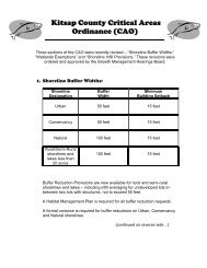
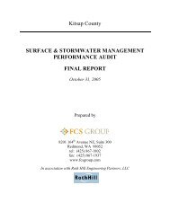
for the Central Kitsap planning areas are presented in Table ES-2. A vicinity map showing the general<br />
planning area for Central Kitsap is provided in Figure ES-2.<br />
Year<br />
Table ES-2. Equivalent Sewered Population for CKWWTP Service Area and Poulsbo<br />
Central<br />
Kitsap<br />
UGA<br />
Silverdale<br />
UGA<br />
Southern<br />
Service<br />
Area total a<br />
Poulsbo<br />
Bangor<br />
Keyport<br />
(base)<br />
Northern<br />
Service<br />
Area total<br />
Total<br />
system<br />
2006 14,100 16,900 32,200 7,500 5,400 1,900 15,000 47,200<br />
2015 23,700 23,800 48,900 9,700 7,700 2,700 20,300 69,200<br />
2025 33,800 31,400 66,800 12,700 10,000 3,500 26,400 93,200<br />
ES-4<br />
DRAFT for review purposes only.<br />
Use of contents on this sheet is subject to the limitations specified at the end of this document.<br />
P:\132857 Kitsap WW Facility Plan Ph II\600 Facility Plan\Revision 3 Draft Final Facility Plan\Executive Summary\Executive Summary(BP).doc
WRIGHT BLISS<br />
MAY<br />
P o<br />
J e f f e r s o n<br />
C o u n t y<br />
H o o d C a n a l<br />
PIONEER<br />
FINN HILL<br />
LOFALL<br />
PIONEER HILL<br />
VIKING<br />
BIG VA LL EY<br />
S AWDU ST HILL<br />
STOTTLEMEYER<br />
STOTTLEME YER<br />
BOND<br />
LINCOLN<br />
PORT GAM BLE<br />
MILLER BAY<br />
NORTHERN SERVICE<br />
AREAS<br />
GUNDERSON<br />
I N<br />
STATE HWY 104<br />
DIA<br />
NO LA<br />
Kingston UGA<br />
WEST KINGSTON<br />
SOU TH KINGSTON<br />
CO LUMBIA<br />
City of Poulsbo<br />
CLEAR CREEK<br />
STATE HWY 3<br />
FRONT<br />
AUGUSTA<br />
Naval Submarine<br />
Base Bangor<br />
HOSTMARK<br />
FJOR D<br />
NOLL<br />
TOTTEN<br />
SUQUAMISH<br />
DIVISION<br />
P o r t M a d i s o n<br />
B a y<br />
L i b e r t y B a y<br />
LEM OLO SHOR E<br />
STA T E H W Y 305<br />
Lemolo<br />
:<br />
1 inch equals 2 miles<br />
Miles<br />
0 0.5 1 2<br />
H o o d C a n a l<br />
OLYMPIC VIEW<br />
ANDERSON HILL<br />
TRIGGER<br />
<strong>KITSAP</strong> MALL<br />
LUOTO<br />
Silverdale UGA<br />
LUOTO<br />
SILVERDALE<br />
RIDGE T OP<br />
BUCKLIN HILL<br />
<strong>CENTRAL</strong> VALLEY<br />
ST ATE H W<br />
WAAGA<br />
£¤ 308<br />
Y 308<br />
Keyport<br />
ILLAHE E<br />
r t O<br />
r d B a y<br />
a<br />
r c h<br />
MILLER<br />
MILLER<br />
STATE HWY 305<br />
MILLER<br />
KOURA<br />
PHELPS<br />
DAY<br />
EUCLID<br />
VALLEY<br />
MADISON<br />
LAFAYETTE<br />
SUNRISE<br />
MIA MI BE<br />
STAVIS BA Y<br />
SEAB ECK HOLLY<br />
A CH<br />
GOLD CRE EK<br />
SOUTHERN SERVICE<br />
AREAS<br />
HOLLY<br />
SEABECK HY<br />
NEWBERRY HILL<br />
City of Bremerton<br />
STATE HWY 3<br />
CHICO<br />
Silverdale<br />
NO RTHLAKE<br />
Bremerton West UGA<br />
K<br />
ITSA P<br />
TRACYTON<br />
FAIRGROUNDS<br />
BAY<br />
CHARLESTON<br />
RIDDELL<br />
11TH<br />
LEBO<br />
WARREN<br />
6TH<br />
STATE HWY 303<br />
BURWELL<br />
JOHN CARLSON<br />
£¤ 303<br />
Central Kitsap UGA<br />
D y e s I n l e t<br />
£¤ 3 Bremerton East UGA<br />
HOLLAND<br />
PINE<br />
WHEATON<br />
MCWILLIAMS<br />
SYLVAN<br />
PERRY<br />
SHERIDAN<br />
WASHINGTON<br />
BAY<br />
W HEA TON<br />
PERRY<br />
City of Port Orchard<br />
B<br />
TRENTON<br />
OLNEY<br />
EA C H<br />
3RD<br />
WISE<br />
ILLAHEE<br />
BEACH<br />
IIlahee<br />
P o r t O r c h a r d B a y<br />
MILE HILL<br />
City of Bainbridge Island<br />
WOODS<br />
CALIFORNIA<br />
FL ETCHER BAY<br />
POI NT WHITE<br />
CHESTER<br />
ALASKA<br />
BUCKLIN H<br />
MAIN<br />
COLC H ES TER<br />
ILL<br />
BLAKELY<br />
HIGH SCHOOL<br />
WYATT<br />
MADISON<br />
E AGLE H<br />
FORT WAR D HILL<br />
A RBO R<br />
ROCKAWAY BEACH<br />
COUNTRY CLUB<br />
BELFAIR VALLEY<br />
T REMONT<br />
BERRY LAKE<br />
SIDNEY<br />
LUND<br />
JACKSON<br />
SALMONBERRY<br />
LOCKER<br />
BANNER<br />
SOU THW ORTH<br />
SUNNYSLOP E<br />
J M DICKENSON<br />
LAKE FLORA<br />
LAKE HELENA<br />
WILDWOOD<br />
LIDER<br />
SIDNEY<br />
LAKEWAY<br />
BETHEL<br />
BETHEL BURLEY<br />
PHILLIPS<br />
PHILLIPS<br />
SEDGWICK<br />
LONG LAKE<br />
MULLENIX<br />
OLALLA VALLEY<br />
BANNER<br />
FIGURE ES-2 1-1<br />
<strong>CENTRAL</strong> <strong>KITSAP</strong><br />
<strong>PLAN</strong>NING AREAS<br />
LEGEND<br />
Central Kitsap UGA<br />
Silverdale UGA<br />
Urban Growth Areas<br />
Incorporated City Limits<br />
Data sources supplied by Kitsap County 2007, and may not reflect actual or current conditions. This map is a geographic representation based<br />
on information available. It does not represent survey data. No warranty is made concerning the accuracy, currency, or completeness of data depicted on this map.<br />
GLENWOOD<br />
Military Locations<br />
State HWY/Route<br />
Principal Arterial<br />
PINE<br />
Water Bodies<br />
Water Courses<br />
BURLEY OLALLA<br />
STEVENS<br />
STATE HWY 16<br />
NELSON<br />
<strong>KITSAP</strong> <strong>COUNTY</strong> PUBLIC WORKS<br />
DRAFT<br />
<strong>CENTRAL</strong> <strong>KITSAP</strong> <strong>WASTEWATER</strong><br />
PHASE II <strong>WASTEWATER</strong><br />
<strong>FACILITY</strong> <strong>PLAN</strong><br />
FACILITIES <strong>PLAN</strong><br />
MAP DATE: DECEMBER 2007<br />
P:\Mapping\Maps_Generated\KitsapCounty\Projects\07_10072.00\task\220\maps\122007\Fig01-1CK_PlanAreas_11x17.mxd
Central Kitsap County Wastewater Facility Plan<br />
Executive Summary<br />
ES-2.2<br />
Wastewater Characteristics<br />
Wastewater flows and loadings also heavily influence facility design. Consequently, data related to wastewater<br />
characteristics and projected flows and loadings affect the selection of key criteria used to select project<br />
alternatives for further consideration. Flows affect the hydraulic capacity of the treatment plant, and loadings,<br />
characterized by biochemical oxygen demand (BOD) and total suspended solids (TSS) relating to sewage<br />
strength, impact the sewage treatment capacity at the Central Kitsap Wastewater Treatment Plant<br />
(CKWWTP). Existing wastewater flows and loadings are characterized and projected in proportion to the<br />
estimated population expected to be served. This information is used to develop the future target capacity<br />
requirements for new wastewater systems. Projected flows and loadings for the CKWWTP are presented in<br />
Table ES-3.<br />
Table ES-3. Projected Flows and Loadings at CKWWTP<br />
Raw influent parameter Current design a 2025<br />
Average annual flow (AAF), mgd 4.6 8.82<br />
Average design flow (ADF), mgd 6.0 11.1<br />
Peak design flow (PDF), mgd<br />
Average peak month BOD5, ppd<br />
Average peak month TSS, ppd<br />
15.0<br />
14,100<br />
11,400<br />
30.4<br />
17,800<br />
17,100<br />
a. Corresponds to Contract I design flows and loads, except for average peak month total suspended solids (TSS) and 5-day<br />
biochemical oxygen demand (BOD5) loadings, which correspond to the design loadings shown in the current National Pollutant<br />
Discharge Elimination System (NPDES) permit. The average design flow (ADF) for the secondary treatment system has been re-rated<br />
from 6 to 7 mgd per letter from Department of Ecology, July 28, 2008.<br />
ES-2.3<br />
Existing Wastewater System Condition<br />
One of the basic objectives of facility planning is to evaluate the feasibility and cost-effectiveness of<br />
incorporating existing systems into a comprehensive wastewater management program. Accordingly,<br />
information regarding the characteristics and conditions of the existing system is analyzed to define each<br />
component’s potential role in the long-term program. Maximum utilization of existing facilities is considered<br />
as the baseline condition for planning improvements.<br />
This Facility Plan provides a description of the nature and general condition of the current wastewater<br />
system. This analysis provides an understanding of how the existing system functions. Major problem areas<br />
and existing, known deficiencies are identified; these deficiencies form the basis for recommended system<br />
upgrade and expansion programs.<br />
ES-2.4<br />
NPDES Permit and Other Regulations<br />
Federal, state, regional, and local regulations also play an important role in the process by which project<br />
alternatives are selected for consideration. Numerous regulations, laws, and policies affect the design,<br />
construction, and operation of wastewater facilities. This Facility Plan describes the various regulations—<br />
particularly the National Pollutant Discharge Elimination System (NPDES) permit—that relate to wastewater<br />
planning for the Central Kitsap planning area.<br />
ES-5<br />
DRAFT for review purposes only.<br />
Use of contents on this sheet is subject to the limitations specified at the end of this document.<br />
P:\132857 Kitsap WW Facility Plan Ph II\600 Facility Plan\Revision 3 Draft Final Facility Plan\Executive Summary\Executive Summary(BP).doc
Executive Summary<br />
Central Kitsap County Wastewater Facility Plan<br />
ES-3<br />
Facilities Design and Evaluation Criteria and<br />
Methodology<br />
After a thorough analysis of the factors influencing project alternatives has been completed, a carefully<br />
crafted methodology is applied to narrow the field of viable alternatives. Through this evaluation process, the<br />
optimal combination of technologies emerges. In developing project alternatives designed to perform a given<br />
function, each project must be evaluated in sufficient detail to reveal project similarities and differences. Only<br />
then can reliable comparisons be made and alternatives ranked accordingly.<br />
This Facility Plan presents a thorough discussion of the key criteria used to evaluate specific projects for<br />
collection and treatment systems. These criteria and subsequent applied methodologies for collection system<br />
projects necessarily vary in scope and composition for alternatives used for treatment system projects.<br />
ES-4<br />
Wastewater System Project Recommendations<br />
The first several chapters of this Facility Plan establish the foundation for a sound, systematic decisionmaking<br />
process. After key criteria have been established, the task of applying them to wastewater<br />
infrastructure project alternatives to develop recommendations begins.<br />
ES-4.1<br />
Collection System Improvements<br />
This Facility Plan provides the identification, evaluation, and ranking of projects required for the existing<br />
sewer system and for new sewer infrastructure. These projects are separated into two main categories: lift<br />
stations and piping. A detailed review of collection projects for the 2005–2025 planning period is provided,<br />
along with cost estimates for all projects.<br />
The total project cost to the County for all recommended existing and future piping and lift station<br />
improvement projects for existing and future flows is $317 million. The costs for upgrading of existing<br />
conveyance system facilities is fully assigned to the County, whereas costs for future facilities to handle<br />
growth is assigned at 75 percent to the County and 25 percent to future developers. The breakdown of this<br />
cost is shown in Table ES-4.<br />
Table ES-4. Summary of Total Collection System Improvements, Construction, and Project Costs<br />
Project category<br />
Total project cost<br />
Existing piping improvements for existing flows $29,140,000<br />
Existing piping improvements for future flows $47,860,000<br />
Existing lift stations $74,360,000<br />
Future lift stations<br />
$43,650,000 a,b<br />
Future piping<br />
$133,880,000 a<br />
Total $328,900,000<br />
a. Estimated cost of future lift stations and future piping to the County. The County cost is 75 percent of the total cost with the remainder<br />
assumed to be paid for by future developers.<br />
b. Costs do not include land acquisition.<br />
ES-6<br />
DRAFT for review purposes only.<br />
Use of contents on this sheet is subject to the limitations specified at the end of this document.<br />
P:\132857 Kitsap WW Facility Plan Ph II\600 Facility Plan\Revision 3 Draft Final Facility Plan\Executive Summary\Executive Summary(BP).doc
Central Kitsap County Wastewater Facility Plan<br />
Executive Summary<br />
ES-4.2<br />
Treatment System Improvements<br />
After collection system recommendations are made, this Facility Plan carries project evaluation process<br />
forward to the wastewater treatment system. The key criteria described above are applied to all feasible<br />
treatment alternatives, resulting in a final set of recommendations.<br />
A two-step process is used to assess possible treatment alternatives. An initial pass/fail evaluation is<br />
performed to determine which unit processes merit further consideration. A final evaluation of some of the<br />
treatment alternatives is then conducted. This final evaluation concludes with a ranking of alternatives and a<br />
description of the recommended improvements encompassing the best overall treatment strategies and<br />
technologies.<br />
These recommendations for wastewater treatment, reuse, and solids treatment are summarized in Table ES-5.<br />
The total project cost for these recommendations, including all of the features necessary to comprise a<br />
complete project at the CKWWTP, is approximately $85.2 million. This estimate does not include the cost of<br />
the headworks improvement project currently under implementation.<br />
Process train<br />
Liquid-stream treatment<br />
Water reclamation<br />
Solids treatment/<br />
biosolids disposal<br />
Biogas utilization/energy usage<br />
Table ES-5. Summary of Recommended Facilities for CKWWTP<br />
Recommendations<br />
• Construct new headworks with screens, aerated grit tanks, and a septage receiving<br />
station (under implementation).<br />
• Replace existing primary clarifiers with new conventional primary clarifiers.<br />
• Aeration basin channel modifications (hydraulic loading).<br />
• New aeration air blowers (capacity).<br />
• In the short term, stay with conventional activated sludge (CAS) system, modified to<br />
allow summer nitrification. The diffuser membranes will also be replaced to increase<br />
aeration capacity.<br />
• To produce reclaimed water, modify and expand CAS system to provide total nitrogen<br />
(TN) removal and add tertiary filters as needed to match the demand for reclaimed<br />
water.<br />
• Additional secondary clarifiers.<br />
• Ultraviolet (UV) system modifications.<br />
• Provide reclaimed water at the CKWWTP instead of construction of satellite plants.<br />
• The decision to reclaim all or a portion of the CKWWTP effluent is largely driven by<br />
policy issues and the prevalence of reclaimed water uses.<br />
• Add gravity belt thickener (GBT) for waste activated sludge (WAS) thickening and keep<br />
gravity thickeners for primary sludge thickening only.<br />
• Stay with conventional mesophilic anaerobic digestion until regulations and/or market for<br />
biosolids disposal drive the need for Class A biosolids. Add additional digester.<br />
• The existing system will be modified to provide the flexibility to produce Class A<br />
biosolids in the future.<br />
• Continue to send Class B biosolids to Fire Mountain Farm or similar facility for disposal.<br />
• Upgrade the biogas management system to convert from the existing fuel-oil-based<br />
digester heating to biogas based heating.<br />
• Conduct further evaluation of combined heat and power generation (cogeneration).<br />
• Conduct an energy audit on existing plant equipment to identify means for increasing<br />
higher energy efficiency of key process equipment.<br />
ES-7<br />
DRAFT for review purposes only.<br />
Use of contents on this sheet is subject to the limitations specified at the end of this document.<br />
P:\132857 Kitsap WW Facility Plan Ph II\600 Facility Plan\Revision 3 Draft Final Facility Plan\Executive Summary\Executive Summary(BP).doc
Executive Summary<br />
Central Kitsap County Wastewater Facility Plan<br />
It is important to note that options to further improve reuse can still be added, if funding or other current<br />
market conditions make such upgrades more economical. The current baseline set of recommendations<br />
provides a foundation upon which potential future add-on projects can be built when timing, conditions, and<br />
policy decisions dictate. Certain infrastructure improvements are essential, and others are desirable;<br />
recommendations are prioritized in this order. An explanation of the cost differences between the baseline<br />
recommendations and those that would further improve reuse is provided in Section 4.3 below.<br />
ES-4.3<br />
Total Recommended Project Costs<br />
Because recommendations can be prioritized according to three primary distinctions, three sets of cost<br />
summaries are provided—required “base case” projects and projects that would take full advantage of<br />
opportunities to expand sustainability. The recommendations that promote reuse are included, even though<br />
they are currently not the most cost-effective choice, because the County has determined that moving in this<br />
direction is a high priority. The three reuse alternatives are described as follows:<br />
• the “base case” project with all necessary collection and treatment system improvements and providing<br />
for optimal energy efficiency, but with no water reuse<br />
• the “base case” project with partial water reuse (approximately 32 percent of plant design capacity)<br />
capable of producing up to 3.5 million gallons per day (mgd) of reclaimed water (Section 8.3.2.1.1)<br />
• the “base case” project with full water reuse (100 percent of plant capacity) resulting in a zero-discharge<br />
wastewater treatment plant.<br />
The total costs for recommended existing and future wastewater infrastructure projects for the Central Kitsap<br />
planning area for the 2005–2025 planning period are shown in Table ES-6.<br />
Treatment<br />
Table ES-6. Summary of Total Infrastructure Improvement Project Costs<br />
Project category<br />
No reuse<br />
Partial reuse (3.5<br />
mgd)<br />
Full reuse<br />
Primary clarifiers $14,580,000 $14,580,000 $14,580,000<br />
Aeration basins $8,320,000 $8,320,000 $0<br />
Aeration blower $630,000 $630,000 $0<br />
Secondary clarifiers $15,400,000 $15,400,000 $15,400,000<br />
Gravity belt thickener $7,070,000 $7,070,000 $7,070,000<br />
Digester improvements $21,590,000 $21,590,000 $21,590,000<br />
Other plant improvements $17,620,000 $17,620,000 $17,620,000<br />
Reuse facilities $0 $28,000,000 $68,290,000<br />
Treatment subtotal $85,210,000 $113,210,000 $144,550,000<br />
Collection (from Chapter 7):<br />
Existing conveyance<br />
New conveyance a<br />
$103,500,000<br />
$225,400,000<br />
$103,500,000<br />
$225,400,000<br />
$103,500,000<br />
$225,400,000<br />
Collection subtotal $328,900,000 $328,900,000 $328,900,000<br />
Grand total $414,100,000 $442,100,000 $473,500,000<br />
a. The total cost for this project category is $284,700,000. The reduced value shown in this table includes a 25 percent reduction for the construction of new<br />
facilities to serve future flows. The cost difference is are assumed to be the responsibility of future developers.<br />
ES-8<br />
DRAFT for review purposes only.<br />
Use of contents on this sheet is subject to the limitations specified at the end of this document.<br />
P:\132857 Kitsap WW Facility Plan Ph II\600 Facility Plan\Revision 3 Draft Final Facility Plan\Executive Summary\Executive Summary(BP).doc
Central Kitsap County Wastewater Facility Plan<br />
Executive Summary<br />
The cost of the collection portion does not change between the three reuse scenarios shown in Table ES-6.<br />
The limiting factor for some of the sustainability-enhancing projects is not the available technology, but the<br />
current market for product, availability of facilities to handle product, and/or regulatory conditions. The final<br />
decision about which reuse scenario the County selects will depend on the monetary impacts to County<br />
finances and rates (Chapter 9) and resultant policies established by County officials. Water reuse is not<br />
currently required by regulation and its implementation for the CKWWTP is likely to remain voluntary for<br />
the planning horizon of this Facility Plan.<br />
Information on capital expenditures is shown in Figures ES-3, ES-4, and ES-5, for the no-reuse, partial-reuse,<br />
and full-reuse scenarios, respectively. The data shown in these three figures are factored into the financial and<br />
rate assessments in Chapter 9.<br />
Expenditures, $2009<br />
Total Central Kitsap WW Facilities Capital Expenditures with No<br />
Reuse<br />
Total County Cost $414 Million<br />
$90,000,000<br />
$80,000,000<br />
$70,000,000<br />
$60,000,000<br />
$50,000,000<br />
$40,000,000<br />
$30,000,000<br />
$20,000,000<br />
$10,000,000<br />
$0<br />
2010<br />
2012<br />
2014<br />
2016<br />
2018<br />
Year<br />
Figure ES-3. Total Central Kitsap wastewater facilities capital expenditures with no reuse<br />
2020<br />
2022<br />
2024<br />
Base Treatment<br />
Future Conveyance Flow s<br />
Existing Conveyance Flow s<br />
ES-9<br />
DRAFT for review purposes only.<br />
Use of contents on this sheet is subject to the limitations specified at the end of this document.<br />
P:\132857 Kitsap WW Facility Plan Ph II\600 Facility Plan\Revision 3 Draft Final Facility Plan\Executive Summary\Executive Summary(BP).doc
Executive Summary<br />
Central Kitsap County Wastewater Facility Plan<br />
Total Central Kitsap WW Facilities Capital Expenditures with Partial<br />
Reuse<br />
Total County Cost $442 Million<br />
$90,000,000<br />
$80,000,000<br />
Expenditures, $2009<br />
$70,000,000<br />
$60,000,000<br />
$50,000,000<br />
$40,000,000<br />
$30,000,000<br />
$20,000,000<br />
Partial Reuse<br />
Base Treatment<br />
Future Conveyance Flow s<br />
Existing Conveyance Flow s<br />
$10,000,000<br />
$0<br />
2010<br />
2012<br />
2014<br />
2016<br />
2018<br />
Year<br />
2020<br />
2022<br />
2024<br />
Figure ES-4. Total Central Kitsap wastewater facilities capital expenditures with partial reuse<br />
ES-10<br />
DRAFT for review purposes only.<br />
Use of contents on this sheet is subject to the limitations specified at the end of this document.<br />
P:\132857 Kitsap WW Facility Plan Ph II\600 Facility Plan\Revision 3 Draft Final Facility Plan\Executive Summary\Executive Summary(BP).doc
Central Kitsap County Wastewater Facility Plan<br />
Executive Summary<br />
Total Central Kitsap WW Facilities Capital Expenditures with<br />
Full Reuse<br />
Total County Cost $474 Million<br />
$90,000,000<br />
$80,000,000<br />
Expenditures, $2009<br />
$70,000,000<br />
$60,000,000<br />
$50,000,000<br />
$40,000,000<br />
$30,000,000<br />
$20,000,000<br />
Full Reuse<br />
Base Treatment<br />
Future Conveyance Flow s<br />
Existing Conveyance Flow s<br />
$10,000,000<br />
$0<br />
2010<br />
2012<br />
2014<br />
2016<br />
2018<br />
2020<br />
2022<br />
2024<br />
Year<br />
Figure ES-5. Total Central Kitsap wastewater facilities capital expenditures with full reuse<br />
ES-5<br />
Financing Evaluation<br />
The impact that the Central Kitsap County wastewater Capital Improvement Program (CIP) will have on<br />
wastewater utility customers is an important factor in determining an appropriate level of service to the<br />
community. Consequently, an evaluation of the CIP financing plan and subsequent customer rate impacts is<br />
necessary to support the selection of the recommended project alternatives for this Facility Plan.<br />
A CIP financing plan for the following three alternatives was developed:<br />
• Alternative 1: CKWWTP with no reuse (secondary treatment only) would require an annual bond<br />
payment by 2025 of $37 million.<br />
• Alternative 2: CKWWTP with partial reuse (3.5 mgd) would require an annual bond payment by 2025 of<br />
$40 million.<br />
• Alternative 3: CKWWTP with full reuse would require an annual bond payment by 2025 of $42.6 million.<br />
To fund the CIP and ongoing operations, the wastewater system revenues would need to be increased over<br />
current rates by between 330 and 365 percent by 2025, depending on which reuse alternative is selected. In<br />
assessing the implications of these projected rate increases, it is important to note that several of the<br />
underlying assumptions are conservative and that deviations from these assumed conditions will likely lessen<br />
future rate increases. These assumptions relate to potential reclaimed water revenue, population projections,<br />
ES-11<br />
DRAFT for review purposes only.<br />
Use of contents on this sheet is subject to the limitations specified at the end of this document.<br />
P:\132857 Kitsap WW Facility Plan Ph II\600 Facility Plan\Revision 3 Draft Final Facility Plan\Executive Summary\Executive Summary(BP).doc
Executive Summary<br />
Central Kitsap County Wastewater Facility Plan<br />
grant funding opportunities, possible private/public or interlocal partnerships, and the proportion of future<br />
improvements to be funded by private developers.<br />
A summary of rate impacts associated with the three reuse alternatives is shown in Figure ES-6. Future<br />
collection systems significantly affect rates, whereas the comparative rate impact of various optional reuse<br />
alternatives is much less. A significant portion of this increase (approximately 40 percent of the total rate or<br />
approximately equivalent to $90/month of the projected year 2025 rate) will be necessary to expand the<br />
collection system into developing areas to serve future growth.<br />
$300<br />
Monthy Residential Rate<br />
$250<br />
$200<br />
$150<br />
$100<br />
$50<br />
$0<br />
Alternative 1:<br />
No Reuse<br />
Alternative 2:<br />
Partial Reuse<br />
Alternative 3:<br />
Full Reuse<br />
Year<br />
2010<br />
2012<br />
2014<br />
2016<br />
2018<br />
2020<br />
2022<br />
2024<br />
Year<br />
Figure ES-6. Annual rate impact summary<br />
Given the substantive impacts of these assumptions, the County, development community, municipalities,<br />
and other agencies could choose to use the future projected rates as a baseline, “worst-case” scenario for<br />
exploring and justifying alternative water conservation and reuse projects and policies, as well as alternative<br />
capital cost-sharing arrangements.<br />
ES-6<br />
Recommended Wastewater System Capital<br />
Improvements<br />
To be determined pending review of this draft.<br />
ES-12<br />
DRAFT for review purposes only.<br />
Use of contents on this sheet is subject to the limitations specified at the end of this document.<br />
P:\132857 Kitsap WW Facility Plan Ph II\600 Facility Plan\Revision 3 Draft Final Facility Plan\Executive Summary\Executive Summary(BP).doc
CHAPTER 1<br />
INTRODUCTION<br />
Kitsap County Public Works is responsible for providing sewerage service to unincorporated central Kitsap<br />
County. Its overall goal is to protect public health and the quality of water resources. The purpose of this<br />
2009 Facility Plan is to provide guidance for the systematic and cost-effective development of wastewater<br />
facilities required to meet these goals under projected growth levels for the 2005–2025 planning period.<br />
Recommendations found in this Facility Plan are influenced by land use priorities, recent technological<br />
innovations in wastewater treatment and reuse, changing regulations, and Kitsap County’s commitment to<br />
move in a more environmentally sustainable direction.<br />
This Facility Plan will allow the County to manage growth within the context of a countywide wastewater<br />
service network. It also must comply with Washington Department of Ecology (Ecology) regulations for<br />
facilities plans (WAC 173-240-060), and it highlights opportunities for Kitsap County to promote reuse.<br />
1.1 Background and Purpose<br />
Kitsap County has prepared several sewerage planning documents since the 1960s. As development occurred<br />
in the late 1960s, dry-line sewers were constructed in anticipation of the addition of County sewerage facilities<br />
in the Central Kitsap planning area. The CKWWTP was constructed and first put into service in 1979. With<br />
the installation of the Navy base at Bangor, and significant growth in the Silverdale and Meadowdale areas,<br />
this wastewater service area has become the largest sewered area within unincorporated Kitsap County.<br />
The last wastewater facility plan for the Central Kitsap planning area was prepared in 1994 and updated in<br />
1999. Since then, the Central Kitsap planning area, and the County as a whole, has grown substantially. With<br />
this growth, the need for a renewed evaluation of sewerage service to the entire County became increasingly<br />
apparent. This Facility Plan presents the findings and recommendations for the Central Kitsap wastewater<br />
facilities.<br />
All project alternatives are identified to serve the 20-year planning period (2005–2025). The 2025 populations<br />
established by the Kitsap County Department of Community Development (DCD) serve as the basis for the<br />
future densities modeled for tributary areas. Depending on the actual growth rate, the anticipated 2025<br />
population may occur sooner or later than projected. Within the study area, some tributary areas may develop<br />
to DCD-estimated densities much sooner than others. This study deals with the average overall density<br />
without respect to time.<br />
Also, within the last 15 years a shift in emphasis has occurred within the environmental, regulatory, and<br />
industry communities toward wastewater reuse, as well as increased energy efficiency. This Facility Plan<br />
explores technologies and strategies that would maximize the efficiency and sustainability of the Central<br />
Kitsap wastewater system.<br />
1-1<br />
DRAFT for review purposes only.<br />
Use of contents on this sheet is subject to the limitations specified at the end of this document.<br />
P:\132857 Kitsap WW Facility Plan Ph II\600 Facility Plan\Revision 3 Draft Final Facility Plan\Chapter 1\Chapter 1_draft.doc
1: Introduction Central Kitsap County Wastewater Facility Plan<br />
1.2 General Planning Area Definition<br />
A vicinity map showing the general Central Kitsap planning area is provided in Figure 1-1. The planning area<br />
is narrowed in scope as physical, regulatory, and jurisdictional considerations are taken into account; this is<br />
described in Chapter 2. This modified area becomes the study area for which specific recommendations are<br />
made.<br />
1.3 Description of Scope of Work<br />
This Facility Plan presents a through analysis of the factors that affect the selection of project alternatives<br />
over a 20-year period (2005–2025):<br />
• planning area characteristics and population projections<br />
• estimated wastewater flows and loadings<br />
• condition of existing wastewater infrastructure<br />
• current regulations<br />
Based on these factors, a methodology is established by which capital projects for wastewater collection,<br />
treatment, and reuse are identified, evaluated against relevant criteria, and ranked. The key criteria that most<br />
heavily influence the selection of future projects for further consideration are shown in Table 1-1. By<br />
systematically screening all project alternatives against these criteria, the field of alternatives is narrowed and<br />
the optimal combination of technologies emerges. Resultant project recommendations are provided—both<br />
with and without reuse alternatives—and cost estimates are provided.<br />
Table 1-1. Key Criteria Affecting Wastewater Capital Projects<br />
Key criterion<br />
Facility Plan chapters where discussed<br />
1. Correct known wastewater system deficiencies 4, 7<br />
2. Repair and replace aged assets 4<br />
3. Provide wastewater service capacity for planning period growth<br />
3<br />
(serving wastewater flow and load projections)<br />
4. Regulatory compliance (present and future) 4, 5<br />
5. Land use 2, 7, 8<br />
6. Accepted engineering design criteria 6, 7, 8<br />
7. Best available technologies 8<br />
8. System operational considerations 8<br />
9. Flexibility for future expansion 7, 8<br />
10. Reclaimed water utilization 8<br />
11. Energy usage 8<br />
12. Biosolids utilization 8<br />
13. Environmental and sensitive area concerns 2, 7, 8<br />
14. Community considerations 7, 8<br />
15. Planning-level costs 6, 7, 8, 9<br />
1-2<br />
DRAFT for review purposes only.<br />
Use of contents on this sheet is subject to the limitations specified at the end of this document.<br />
P:\132857 Kitsap WW Facility Plan Ph II\600 Facility Plan\Revision 3 Draft Final Facility Plan\Chapter 1\Chapter 1_draft.doc
WRIGHT BLISS<br />
MAY<br />
P o<br />
J e f f e r s o n<br />
C o u n t y<br />
H o o d C a n a l<br />
PIONEER<br />
FINN HILL<br />
LOFALL<br />
PIONEER HILL<br />
VIKING<br />
BIG VA LL EY<br />
S AWDU ST HILL<br />
STOTTLEMEYER<br />
STOTTLEME YER<br />
BOND<br />
LINCOLN<br />
PORT GAM BLE<br />
MILLER BAY<br />
NORTHERN SERVICE<br />
AREAS<br />
GUNDERSON<br />
I N<br />
STATE HWY 104<br />
DIA<br />
NO LA<br />
Kingston UGA<br />
WEST KINGSTON<br />
SOU TH KINGSTON<br />
CO LUMBIA<br />
City of Poulsbo<br />
CLEAR CREEK<br />
STATE HWY 3<br />
FRONT<br />
AUGUSTA<br />
Naval Submarine<br />
Base Bangor<br />
HOSTMARK<br />
FJOR D<br />
NOLL<br />
TOTTEN<br />
SUQUAMISH<br />
DIVISION<br />
P o r t M a d i s o n<br />
B a y<br />
L i b e r t y B a y<br />
LEM OLO SHOR E<br />
STA T E H W Y 305<br />
Lemolo<br />
:<br />
1 inch equals 2 miles<br />
Miles<br />
0 0.5 1 2<br />
H o o d C a n a l<br />
OLYMPIC VIEW<br />
ANDERSON HILL<br />
TRIGGER<br />
<strong>KITSAP</strong> MALL<br />
LUOTO<br />
Silverdale UGA<br />
LUOTO<br />
SILVERDALE<br />
RIDGE T OP<br />
BUCKLIN HILL<br />
<strong>CENTRAL</strong> VALLEY<br />
ST ATE H W<br />
WAAGA<br />
£¤ 308<br />
Y 308<br />
Keyport<br />
ILLAHE E<br />
r t O<br />
r d B a y<br />
a<br />
r c h<br />
MILLER<br />
MILLER<br />
STATE HWY 305<br />
MILLER<br />
KOURA<br />
PHELPS<br />
DAY<br />
EUCLID<br />
VALLEY<br />
MADISON<br />
LAFAYETTE<br />
SUNRISE<br />
MIA MI BE<br />
STAVIS BA Y<br />
SEAB ECK HOLLY<br />
A CH<br />
GOLD CRE EK<br />
SOUTHERN SERVICE<br />
AREAS<br />
HOLLY<br />
SEABECK HY<br />
NEWBERRY HILL<br />
City of Bremerton<br />
STATE HWY 3<br />
CHICO<br />
Silverdale<br />
NO RTHLAKE<br />
Bremerton West UGA<br />
K<br />
ITSA P<br />
TRACYTON<br />
FAIRGROUNDS<br />
BAY<br />
CHARLESTON<br />
RIDDELL<br />
11TH<br />
LEBO<br />
WARREN<br />
6TH<br />
STATE HWY 303<br />
BURWELL<br />
JOHN CARLSON<br />
£¤ 303<br />
Central Kitsap UGA<br />
D y e s I n l e t<br />
£¤ 3 Bremerton East UGA<br />
HOLLAND<br />
PINE<br />
WHEATON<br />
MCWILLIAMS<br />
SYLVAN<br />
PERRY<br />
SHERIDAN<br />
WASHINGTON<br />
BAY<br />
W HEA TON<br />
PERRY<br />
City of Port Orchard<br />
B<br />
TRENTON<br />
OLNEY<br />
EA C H<br />
3RD<br />
WISE<br />
ILLAHEE<br />
BEACH<br />
IIlahee<br />
P o r t O r c h a r d B a y<br />
MILE HILL<br />
City of Bainbridge Island<br />
WOODS<br />
CALIFORNIA<br />
FL ETCHER BAY<br />
POI NT WHITE<br />
CHESTER<br />
ALASKA<br />
BUCKLIN H<br />
MAIN<br />
COLC H ES TER<br />
ILL<br />
BLAKELY<br />
HIGH SCHOOL<br />
WYATT<br />
MADISON<br />
E AGLE H<br />
FORT WAR D HILL<br />
A RBO R<br />
ROCKAWAY BEACH<br />
COUNTRY CLUB<br />
BELFAIR VALLEY<br />
T REMONT<br />
BERRY LAKE<br />
SIDNEY<br />
LUND<br />
JACKSON<br />
SALMONBERRY<br />
LOCKER<br />
BANNER<br />
SOU THW ORTH<br />
SUNNYSLOP E<br />
J M DICKENSON<br />
LAKE FLORA<br />
LAKE HELENA<br />
WILDWOOD<br />
LIDER<br />
SIDNEY<br />
LAKEWAY<br />
BETHEL<br />
BETHEL BURLEY<br />
PHILLIPS<br />
PHILLIPS<br />
SEDGWICK<br />
LONG LAKE<br />
MULLENIX<br />
OLALLA VALLEY<br />
BANNER<br />
FIGURE 1-1<br />
<strong>CENTRAL</strong> <strong>KITSAP</strong><br />
<strong>PLAN</strong>NING AREAS<br />
LEGEND<br />
Central Kitsap UGA<br />
Silverdale UGA<br />
Urban Growth Areas<br />
Incorporated City Limits<br />
Data sources supplied by Kitsap County 2007, and may not reflect actual or current conditions. This map is a geographic representation based<br />
on information available. It does not represent survey data. No warranty is made concerning the accuracy, currency, or completeness of data depicted on this map.<br />
GLENWOOD<br />
Military Locations<br />
State HWY/Route<br />
Principal Arterial<br />
PINE<br />
Water Bodies<br />
Water Courses<br />
BURLEY OLALLA<br />
STEVENS<br />
STATE HWY 16<br />
NELSON<br />
<strong>KITSAP</strong> <strong>COUNTY</strong> PUBLIC WORKS<br />
DRAFT<br />
<strong>CENTRAL</strong> <strong>KITSAP</strong> <strong>WASTEWATER</strong><br />
PHASE II <strong>WASTEWATER</strong><br />
<strong>FACILITY</strong> <strong>PLAN</strong><br />
FACILITIES <strong>PLAN</strong><br />
MAP DATE: DECEMBER 2007<br />
P:\Mapping\Maps_Generated\KitsapCounty\Projects\07_10072.00\task\220\maps\122007\Fig01-1CK_PlanAreas_11x17.mxd
Central Kitsap County Wastewater Facility Plan<br />
1: Introduction<br />
It is important to note that water reuse projects have been given high priority. Technologies capable of<br />
treating wastewater to acceptable standards are currently available; currently the limiting factors are the<br />
identification of customers, usage sites, and the resultant understanding of potential reclaimed water demand.<br />
Only capital projects that can be easily supplemented or modified for wastewater reuse, as markets or the<br />
future regulatory climate render these programs feasible, have been identified for consideration.<br />
1.4 Overview of the Facility Plan<br />
This Facility Plan is divided into several chapters to provide an understanding of the current nature of the<br />
service area, and to examine the key criteria and their impacts on the wastewater system. Chapters 2–5<br />
provide descriptions of the planning area, wastewater flows and loadings, the condition of the existing<br />
infrastructure, and regulations that guide system design. Chapter 6 explains the key criteria and evaluation<br />
methodologies applied to select project alternatives for further consideration. Chapters 7 and 8 identify<br />
potential projects for the collection and treatment systems, respectively; they then explain the evaluation and<br />
subsequent ranking of project alternatives and provide initial recommendations. A final comprehensive set of<br />
recommendations and cost estimates are then presented. Chapter 9 presents an evaluation of how these<br />
capital improvements will be financed. Chapter 10—which has not been prepared yet, pending County review<br />
of this draft of the Facility Plan—will present the final set of recommended capital improvements to the<br />
Central Kitsap wastewater collection and treatment infrastructure for the 20-year planning period.<br />
The organization of the Facility Plan is shown in Table 1-2. To facilitate an understanding of terminology<br />
used in this document, a glossary of commonly used technical terms and abbreviations used in this Facility<br />
Plan is provided in Appendix 1.<br />
Table 1-2. Organization of the Central Kitsap County Wastewater Facility Plan<br />
Chapter<br />
Content<br />
1. Introduction 1.1 Background and Purpose<br />
1.2 General Planning Area Definition<br />
1.3 Description of Scope of Work<br />
1.4 Overview of the Facility Plan<br />
2. Planning Area Characteristics 2.1 Overview of Chapter Contents<br />
2.2 Urban Growth Areas<br />
2.3 Planning and Service Areas<br />
2.4 Natural Systems Affecting Wastewater Collection and Treatment<br />
Systems and Reclaimed Water Opportunities<br />
2.5 Population Estimates and Projections<br />
2.6 Land Use and Zoning<br />
2.7 Equivalent Residential Unit Criteria<br />
2.8 Sewered Equivalent Population Projections<br />
3. Wastewater Characteristics 3.1 Overview of Chapter Contents<br />
3.2 Wastewater Flows<br />
3.3 Wastewater Composition and Loadings<br />
4. Description and Condition of Existing Wastewater System 4.1 Overview of Chapter Contents<br />
4.2 Existing Collection Facilities<br />
4.3 Existing Wastewater Treatment Plant<br />
4.4 Outfall and Diffuser<br />
1-3<br />
DRAFT for review purposes only.<br />
Use of contents on this sheet is subject to the limitations specified at the end of this document.<br />
P:\132857 Kitsap WW Facility Plan Ph II\600 Facility Plan\Revision 3 Draft Final Facility Plan\Chapter 1\Chapter 1_draft.doc
1: Introduction Central Kitsap County Wastewater Facility Plan<br />
Table 1-2. Organization of the Central Kitsap County Wastewater Facility Plan<br />
Chapter<br />
Content<br />
5. NPDES Permit and Other Regulations 5.1 Overview of Chapter Contents<br />
5.2 NPDES Permit<br />
5.3 Other Federal, State, Regional, and Local Permits and Regulations<br />
6. Facilities Design and Evaluation Criteria and Methodologies 6.1 Overview of Chapter Contents<br />
6.2 Key Criteria and Methodologies Used to Identify, Evaluate, and Rank<br />
Projects<br />
6.3 Collection System Projects<br />
6.4 Treatment System Projects<br />
7: Collection System Improvements 7.1 Overview of Chapter Contents<br />
7.2 Project Identification<br />
7.3 Project Evaluation<br />
7.4 Project Ranking<br />
7.5 Timeline for Collection System Projects<br />
8. Wastewater Treatment Improvements, Reuse Options, and<br />
Energy Conservation and Generation Opportunities<br />
8.1 Overview of Chapter Contents<br />
8.2 Project Identification<br />
8.3 Project Evaluation<br />
8.4 Project Ranking<br />
8.5 Project Recommendations<br />
8.6 Project Costs<br />
9: Financing Evaluation 9.1 Overview of Chapter Contents<br />
9.2 Capital Improvement Alternatives<br />
9.3 Projected Revenue Requirement<br />
9.4 Projected Revenue Increases Required from Rates<br />
9.5 Conclusions<br />
10. Recommended Wastewater System Capital Improvements Description of Recommended Capital Improvement Projects<br />
Cost and Rate Impact Summary<br />
1-4<br />
DRAFT for review purposes only.<br />
Use of contents on this sheet is subject to the limitations specified at the end of this document.<br />
P:\132857 Kitsap WW Facility Plan Ph II\600 Facility Plan\Revision 3 Draft Final Facility Plan\Chapter 1\Chapter 1_draft.doc
CHAPTER 2<br />
<strong>PLAN</strong>NING AREA CHARACTERISTICS<br />
GMA requirements, planning area physical characteristics, population estimates and projections, and related<br />
land use priorities all play a critical role in determining the key criteria used to select project alternatives for<br />
the CKWWTP facility design in the 20-year planning period. This chapter presents the physical and<br />
demographic characteristics of the planning area, with a focus on features that are considered during the<br />
facility planning process. This information is provided to show how wastewater infrastructure relates to its<br />
community and environs.<br />
The Central Kitsap service areas generally range from Bremerton to Poulsbo and from Port Orchard Bay to<br />
Hood Canal. Specifically, these service areas include the following:<br />
• Central Kitsap Urban Growth Area (UGA)<br />
• Silverdale UGA<br />
• city of Poulsbo and surrounding UGA<br />
• Keyport community<br />
• Bangor and Keyport naval bases.<br />
Additionally, septage collected countywide and biosolids generated at other County WWTPs (Manchester,<br />
Suquamish, and Kingston) are trucked to the CKWWTP for processing and disposal. The locations of these<br />
service areas and treatment plants are shown in Figure 2-1. These areas and their characteristics are discussed<br />
in this chapter.<br />
2.1 Overview of Chapter Contents<br />
This chapter describes the Central Kitsap UGAs established by the Growth Management Act (GMA) and<br />
discusses the GMA’s role in establishing wastewater service requirements. Subsequent sections describe the<br />
physical characteristics of the planning area and its sub-basins including natural systems (e.g., topography,<br />
land use, zoning, sensitive habitats, drinking water aquifers, and geological impediments) that limit<br />
construction of wastewater system improvements and reclaimed water opportunities. Finally, this chapter<br />
discusses service population estimates for the future planning period covered in this Facility Plan.<br />
2.2 Urban Growth Areas<br />
This document differs from the previous Facility Plan (published in 1994 and amended in 1999) by using<br />
UGAs to define the service areas. A UGA is defined by the state of Washington as a mostly contiguous area<br />
around an urbanized area, often a commercial core, within which growth and services can be concentrated<br />
over time, resulting in a more efficient use of public infrastructure.<br />
The state of Washington adopted the GMA in 1990 with the intent of concentrating most new development<br />
within urban areas of the more populous and rapidly growing counties. These counties are required to define<br />
an urban growth boundary within which urban services, like sewers, are provided. New parcels that develop<br />
outside the UGA boundary must be low-density with sufficient acreage to support onsite sewage disposal<br />
systems conforming to county and state health regulations. Once the UGA boundaries have been established,<br />
2-1<br />
DRAFT for review purposes only.<br />
Use of contents on this sheet is subject to the limitations specified at the end of this document.<br />
P:\132857 Kitsap WW Facility Plan Ph II\600 Facility Plan\Revision 3 Draft Final Facility Plan\Chapter 2\September 09 Draft Chapter 2_draft(BP).doc
2: Planning Area Characteristics Central Kitsap County Wastewater Facility Plan<br />
counties can adjust or expand them only within a prescribed planning and legal framework. The Central<br />
Kitsap planning area includes three UGAs as well as several special districts occupied by naval facilities.<br />
For Kitsap County, the UGA boundaries are identified in the Kitsap County Comprehensive Land Use Plan 10-Year<br />
Update, December 2006 (10-Year Update). The 10-Year Update included modifications in the extent of the<br />
Central Kitsap planning and service area as currently defined by the Silverdale and Central Kitsap UGA<br />
boundaries illustrated on Figure 2-2.<br />
Under the GMA, only the four following potential exceptions to the prohibitions of sewers outside of an<br />
urban growth boundary are recognized under state law and case law:<br />
1. Where it is a necessary response to a documented public health or environmental hazard and the<br />
County has determined that providing sewer service is financially supportable and will not permit<br />
urban growth.<br />
2. If the property is an essential public facility and must be served by a sewer in a rural area (this<br />
exception does not include schools, churches, or certain types of residential facilities and depends<br />
specifically on the circumstances surrounding a proposed essential public facility).<br />
3. Where the County has entered into a preexisting contractually binding agreement to provide sewer<br />
service to a property outside of the UGA.<br />
4. Where sewer service is required to service areas of more intensive rural development allowed by the<br />
Kitsap County Comprehensive Plan Land Use Map.<br />
Sewers provided in these cases may be satellite systems limited to serving only the qualified and defined<br />
parcels. Alternatively, a sewer extension may be “tight-lined” to convey wastewater from the qualified and<br />
defined parcels into the urban growth area for connection to the existing sewer system.<br />
2.3 Planning and Service Areas<br />
The central Kitsap County planning area is divided into the Countywide, Northern, and Southern Service<br />
Areas. The various areas and services provided by the County are identified in Table 2-1 below and described<br />
in more detail in the following paragraphs.<br />
Countywide Service Area<br />
Table 2-1. Wastewater Service Responsibilities by Service Area<br />
Collection system owner Owner’s responsibility Kitsap County role<br />
Wastewater treatment and biosolids<br />
Septage haulers Private Private systems<br />
processing and disposal<br />
Other treatment plants Kitsap County Wastewater treatment and biosolids processing and disposal<br />
Future facilities by others<br />
Northern Service Area<br />
Bangor<br />
Keyport Navy<br />
Poulsbo city and UGA<br />
Port Gamble, state parks<br />
MBRs a , other<br />
U.S. Navy<br />
U.S. Navy<br />
Poulsbo city<br />
To be determined<br />
Collection system capital costs<br />
Treatment costs<br />
Flow metering<br />
To be determined<br />
Wastewater treatment<br />
Biosolids<br />
O&M of collection facilities (outside<br />
of Owner’s service area in the<br />
County)<br />
2-2<br />
DRAFT for review purposes only.<br />
Use of contents on this sheet is subject to the limitations specified at the end of this document.<br />
P:\132857 Kitsap WW Facility Plan Ph II\600 Facility Plan\Revision 3 Draft Final Facility Plan\Chapter 2\September 09 Draft Chapter 2_draft(BP).doc
WRIGHT BLISS<br />
MAY<br />
P o<br />
J e f f e r s o n<br />
C o u n t y<br />
H o o d C a n a l<br />
PIONEER<br />
FINN HILL<br />
LOFALL<br />
PIONEER HILL<br />
VIKING<br />
BIG VA LL EY<br />
S AWDU ST HILL<br />
STOTTLEMEYER<br />
STOTTLEME YER<br />
BOND<br />
LINCOLN<br />
PORT GAM BLE<br />
MILLER BAY<br />
NORTHERN SERVICE<br />
AREAS<br />
GUNDERSON<br />
I N<br />
STATE HWY 104<br />
DIA<br />
NO LA<br />
Kingston UGA<br />
WEST KINGSTON<br />
"T<br />
SO UTH KINGSTON<br />
Kingston TP<br />
City of Poulsbo<br />
CO LUMBIA<br />
Naval Submarine<br />
Base Bangor<br />
CLEAR CREEK<br />
STATE HWY 3<br />
FRONT<br />
HOSTMARK<br />
FJOR D<br />
NOLL<br />
TOTTEN<br />
SUQUAMISH<br />
DIVISION<br />
"T<br />
Suquamish TP<br />
P o r t M a d i s o n<br />
B a y<br />
L i b e r t y B a y<br />
LEM OLO SHOR E<br />
STA T E H W Y 305<br />
Lemolo<br />
:<br />
1 inch equals 2 miles<br />
Miles<br />
0 0.5 1 2<br />
H o o d C a n a l<br />
OLYMPIC VIEW<br />
ANDERSON HILL<br />
TRIGGER<br />
<strong>KITSAP</strong> MALL<br />
LUOTO<br />
SILVERDALE<br />
Silverdale UGA<br />
LUOTO<br />
RIDGE T OP<br />
BUCKLIN HILL<br />
<strong>CENTRAL</strong> VALLEY<br />
ST ATE H W<br />
Central Kitsap TP<br />
WAAGA<br />
£¤ 308<br />
Y 308<br />
"T<br />
Keyport<br />
ILLAHE E<br />
r t O<br />
r d B a y<br />
a<br />
r c h<br />
MILLER<br />
MILLER<br />
STATE HWY 305<br />
MILLER<br />
KOURA<br />
PHELPS<br />
DAY<br />
EUCLID<br />
VALLEY<br />
MADISON<br />
LAFAYETTE<br />
SUNRISE<br />
MIA MI BE<br />
STAVIS BA Y<br />
SEAB ECK HOLLY<br />
A CH<br />
GOLD CRE EK<br />
SOUTHERN SERVICE<br />
AREAS<br />
HOLLY<br />
SEABECK HY<br />
NEWBERRY HILL<br />
City of Bremerton<br />
STATE HWY 3<br />
CHICO<br />
Silverdale<br />
NO RTHLAKE<br />
Bremerton West UGA<br />
K<br />
ITSA P<br />
TRACYTON<br />
"T<br />
FAIRGROUNDS<br />
"T<br />
Bremerton TP<br />
BAY<br />
CHARLESTON<br />
RIDDELL<br />
LEBO<br />
11TH<br />
WARREN<br />
6TH<br />
STATE HWY 303<br />
BURWELL<br />
JOHN CARLSON<br />
£¤ 303<br />
Central Kitsap UGA<br />
D y e s I n l e t<br />
£¤ 3 Bremerton East UGA<br />
HOLLAND<br />
PINE<br />
WHEATON<br />
MCWILLIAMS<br />
SYLVAN<br />
PERRY<br />
Bremerton TP<br />
WASHINGTON<br />
BAY<br />
W HEA TON<br />
PERRY<br />
"T<br />
City of Port Orchard<br />
TRENTON<br />
OLNEY<br />
3RD<br />
WISE<br />
ILLAHEE<br />
BEACH<br />
Illahee<br />
P o r t O r c h a r d B a y<br />
PortOrchard TP<br />
MILE HILL<br />
City of Bainbridge Island<br />
WOODS<br />
CALIFORNIA<br />
FL ETCHER BAY<br />
POI NT WHITE<br />
CHESTER<br />
ALASKA<br />
BUCKLIN H<br />
"T<br />
MAIN<br />
COLC H ES TER<br />
ILL<br />
BLAKELY<br />
HIGH SCHOOL<br />
WYATT<br />
MADISON<br />
E AGLE H<br />
FORT WAR D HILL<br />
A RBO R<br />
Manchester TP<br />
ROCKAWAY BEACH<br />
COUNTRY CLUB<br />
BELFAIR VALLEY<br />
T REMONT<br />
BERRY LAKE<br />
SIDNEY<br />
LUND<br />
JACKSON<br />
SALMONBERRY<br />
LOCKER<br />
BANNER<br />
SOU THW ORTH<br />
SUNNYSLOP E<br />
J M DICKENSON<br />
LAKE FLORA<br />
LAKE HELENA<br />
WILDWOOD<br />
LIDER<br />
SIDNEY<br />
LAKEWAY<br />
BETHEL<br />
BETHEL BURLEY<br />
PHILLIPS<br />
PHILLIPS<br />
SEDGWICK<br />
LONG LAKE<br />
MULLENIX<br />
OLALLA VALLEY<br />
BANNER<br />
FIGURE 2-1<br />
SERVICE AREAS &<br />
LOCAL TREATMENT<br />
<strong>PLAN</strong>TS<br />
LEGEND<br />
"T Treatment Plant<br />
Central Kitsap UGA<br />
Silverdale UGA<br />
Urban Growth Areas<br />
Incorporated City Limits<br />
Military Locations<br />
State HWY/Route<br />
Principal Arterial<br />
Data sources supplied by Kitsap County 2007, and may not reflect actual or current conditions. This map is a geographic representation based<br />
on information available. It does not represent survey data. No warranty is made concerning the accuracy, currency, or completeness of data depicted on this map.<br />
GLENWOOD<br />
PINE<br />
Water Bodies<br />
Water Courses<br />
BURLEY OLALLA<br />
STEVENS<br />
STATE HWY 16<br />
NELSON<br />
<strong>KITSAP</strong> <strong>COUNTY</strong> PUBLIC WORKS<br />
<strong>CENTRAL</strong> <strong>KITSAP</strong> <strong>WASTEWATER</strong><br />
GMA <strong>FACILITY</strong> COMPLIANCE <strong>PLAN</strong> <strong>PLAN</strong><br />
MAP DATE: DECEMBER 2007<br />
P:\Mapping\Maps_Generated\KitsapCounty\Projects\07_10072.00\task\220\maps\122007\Fig02-1ServAreas&TPs_11x17.mxd
CHICO WAY NW<br />
MAY ST NW<br />
NO LL R D NE<br />
Poulsbo UGA<br />
L i b e r t y B a y<br />
O L Y MPIC VIEW RD NW<br />
STATE HWY 3 NW<br />
VIKING WAY NW<br />
LEMO LO SHORE DR NE<br />
Lemolo<br />
NE TOTTEN RD<br />
STATE HWY 305 NE<br />
H o o d C a n a l<br />
NW NEWBERRY HILL RD<br />
SEABECK HY NW<br />
Naval Submarine Base Bangor<br />
NW ANDERSO N HIL L RD<br />
Chico<br />
STATE HWY 3 NW<br />
CLEAR CREEK RD NW<br />
RIDGETOP BLVD NW<br />
SILVERDALE W AY NW<br />
NW WAAG A WAY<br />
NW LUOTO RD<br />
£¤ 308<br />
NW TRIGGER AVE<br />
£¤ 303<br />
Silverdale<br />
£¤ 3<br />
<strong>KITSAP</strong> MALL BLVD NW<br />
NW LUOTO RD<br />
D y e s I n l e t<br />
NW BUCKLIN HILL RD<br />
TRACYTON BLVD NW<br />
NW FAIRGROUNDS RD<br />
NW STATE HWY 308<br />
HOLLAND RD NW<br />
TRAC YTON BEACH RD NW<br />
<strong>CENTRAL</strong> VALLEY RD NE<br />
<strong>CENTRAL</strong> VALLEY RD NW<br />
NE WAAGA WAY<br />
NE FAIRGROUNDS RD<br />
NE MCWILLIAMS RD<br />
PINE RD NE<br />
PINE RD<br />
NE STATE H WY 308<br />
SYLVAN WAY<br />
STATE HWY 303 NE<br />
NE RIDDELL RD<br />
Keyport<br />
WHEATON WAY<br />
B ROWNSVILLE HY NE<br />
BR O WNSVILLE HY NE<br />
NE JOHN CARLSON RD<br />
PERRY AVE NE<br />
N e S i K a<br />
B a y<br />
Brownsville<br />
SUNSET AVE NE<br />
ILLAHEE RD NE<br />
NE 3RD ST N<br />
NE WISE<br />
NE SYLVAN WAY<br />
1 inch equals 4,000 feet<br />
Feet<br />
:0 2,000 4,000<br />
ILLAHEE RD NE<br />
OCEAN VIEW BLVD NE<br />
P o r t O r c h a r d B a y<br />
IIlahee<br />
NORTHLAKE WAY NW<br />
City of Bremerton<br />
LEBO B L VD<br />
WARREN AV BRDG<br />
SHERIDAN RD<br />
WHEATO N WAY<br />
PERRY AVE NE<br />
TRENTON AVE NE<br />
Bremerton East UGA<br />
PERRY AVE<br />
TRENTON AVE<br />
FIGURE 2-2<br />
2006 FIGURE LAND 2-8 USE<br />
2006 LAND USE<br />
COMPREHENSIVE <strong>PLAN</strong> DESIGNATIONS<br />
Central Kitsap UGA<br />
Silverdale UGA<br />
Other UGAs<br />
Parcels<br />
State HWY/Route<br />
Rural Residential<br />
Rural Protection<br />
Rural Wooded<br />
Urban Reserve<br />
Mineral Resource<br />
Rural Commercial<br />
Rural Industrial<br />
Urban High-Intensity Commercial/Mixed Use<br />
K<br />
ITSAP WAY<br />
Urban Industrial<br />
Urban Low-Intensity Commercial/Mixed Use<br />
Urban Low-Density Residential<br />
Urban Medium/High-Density Residential<br />
Limited Area of More Intense Rural Development<br />
Incorporated City<br />
Tribal Land<br />
Poulsbo Urban Transition Area<br />
Data sources supplied by Kitsap County 2007, and may not reflect actual or current conditions. This map is a geographic representation based<br />
on information available. It does not represent survey data. No warranty is made concerning the accuracy, currency, or completeness of data depicted on this map.<br />
CH ARLES T O N BLVD<br />
6TH ST<br />
Public Facility<br />
Lake<br />
Salt Water<br />
Airport<br />
Forest Resource Lands<br />
11TH ST<br />
Industrial Mulit-Purpose Recreational Area<br />
Military<br />
6TH ST<br />
WARREN AVE<br />
BURWELL ST<br />
WASHINGTON AVE<br />
E 11TH ST<br />
<strong>KITSAP</strong> <strong>COUNTY</strong> PUBLIC WORKS<br />
BEACH DR E<br />
<strong>CENTRAL</strong> <strong>KITSAP</strong> <strong>WASTEWATER</strong><br />
GMA <strong>FACILITY</strong> COMPLIANCE <strong>PLAN</strong> <strong>PLAN</strong><br />
MAP DATE: DECEMBER 2007<br />
P:\Mapping\Maps_Generated\KitsapCounty\Projects\07_10072.00\task\220\maps\122007\Fig0X_Landuse_11x17.mxd
Central Kitsap County Wastewater Facility Plan<br />
2: Planning Area Characteristics<br />
Table 2-1. Wastewater Service Responsibilities by Service Area<br />
Collection system owner Owner’s responsibility Kitsap County role<br />
Keyport community Kitsap County Infrastructure and O&M for collection and treatment<br />
Southern Service Area<br />
Silverdale UGA<br />
Central Kitsap UGA<br />
Kitsap County<br />
Infrastructure and O&M for collection and treatment<br />
Special connections<br />
a. MBRs: Membrane bioreactors.<br />
2.3.1 Countywide Service Area<br />
The CKWWTP provides biosolids processing and disposal for additional non-contiguous “service areas.”<br />
Biosolids from ancillary treatment plants for Suquamish, Kingston, and Manchester are trucked to the<br />
CKWWTP for processing. Port Gamble may, in the future, expand its wastewater treatment facilities to<br />
accommodate growth. At such time, the County could own and operate the plant or the community could<br />
contract to utilize the CKWWTP facility for biosolids management. Biosolids may also be received from<br />
other smaller WWTPs in the future, such as the membrane bioreactor (MBR) plants being constructed for<br />
state parks on Bainbridge Island and Hood Canal.<br />
2.3.2 Northern Service Area<br />
Flows generated in the Northern Service Area come predominantly from areas that have contracted for or<br />
been allocated portions of the CKWWTP capacity. The contracted areas are Poulsbo and the Keyport naval<br />
base. The Bangor naval base is allocated capacity and served at straight commercial rates. Each of these<br />
service areas is responsible for collection, flow measurement, and collection to the County facilities.<br />
The Navy flows are not expected to increase over the next 20 years; however, a portion of plant capacity is<br />
set aside for the Bangor and Keyport bases. The Keyport community, with a small served population, is the<br />
only residentially permitted flow generator in the Northern Service Area. Keyport is designated as a limited<br />
area of more intense development (LAMIRD) and although it is assumed to currently be near maximum<br />
density, some future connections are permitted for this area. The source of future flow quantities from<br />
Poulsbo is the City of Poulsbo Comprehensive Sanitary Sewer Plan 2008 Update (Poulsbo Sewer Plan) (Parametrix,<br />
2008).<br />
2.3.3 Southern Service Area<br />
The Southern Service Area includes the Silverdale UGA, the Central Kitsap UGA, and special connections.<br />
Population allocations and future estimated flows from the Southern Service Area are based on population<br />
data from the DCD. Future growth in the Southern Service Area will drive the majority of the future<br />
infrastructure needs for wastewater that is generated in the CKWWTP service area.<br />
2.3.3.1 Silverdale UGA<br />
The Silverdale UGA, which has an area of approximately 7,400 gross acres, includes the unincorporated area<br />
of Silverdale and is located to the north and west of Dyes Inlet. Outside of the Silverdale downtown area,<br />
which primarily comprises commercial uses, the surrounding community is suburban in character and has<br />
2-3<br />
DRAFT for review purposes only.<br />
Use of contents on this sheet is subject to the limitations specified at the end of this document.<br />
P:\132857 Kitsap WW Facility Plan Ph II\600 Facility Plan\Revision 3 Draft Final Facility Plan\Chapter 2\September 09 Draft Chapter 2_draft(BP).doc
2: Planning Area Characteristics Central Kitsap County Wastewater Facility Plan<br />
predominantly single family residential development. The Silverdale UGA boundary is shown on Figures 2-1<br />
and 2-2.<br />
2.3.3.2 Central Kitsap UGA<br />
The Central Kitsap UGA, which has an area of approximately 6,400 gross acres, is located just north of the<br />
City of Bremerton between Dyes Inlet to the west and Port Orchard Bay to the east and includes the<br />
community of Illahee. It has a predominantly suburban character with commercial uses concentrated along<br />
State Route (SR) 303 which bisects the area from south to north. The Central Kitsap UGA boundary is<br />
shown on Figures 2-1 and 2-2.<br />
2.3.3.3 Special Connections<br />
Special connections are facilities and areas located outside of the Central Kitsap and Silverdale UGAs that are<br />
allowed by GMA to be connected to the sewer system. Examples include schools and areas that have<br />
documented health issues from using onsite sewage systems.<br />
2.4 Natural Systems Affecting Wastewater Collection and<br />
Treatment Systems and Reclaimed Water Opportunities<br />
This section presents an overview of the natural systems that comprise the central Kitsap County service<br />
areas. The characteristics of these systems have a significant impact on the design of wastewater facilities and<br />
the disposal of treated wastewater and biosolids.<br />
Table 2-2 lists the various characteristics and how each affects elements of wastewater management<br />
infrastructure.<br />
Natural system characteristic<br />
Steep terrain<br />
Impermeable soils<br />
Aquifer recharge areas<br />
Drinking water wells<br />
Impaired water bodies<br />
Geohazards<br />
Flood zones<br />
Wetlands and streams<br />
Wildlife conservation areas<br />
Table 2-2. Natural System Characteristics and Their Effects on<br />
Wastewater Management Infrastructure<br />
Effects on wastewater infrastructure<br />
Unsuitable for construction of wastewater facilities.<br />
Unsuitable for reclaimed water recharge areas.<br />
Provides focus for sewers to serve tributary septic tanks and potential for<br />
indirect reclaimed water recharge.<br />
Setback limits for septic tanks and reclaimed water recharge areas.<br />
Setback limits for septic tanks and wastewater facilities. Provides focus for<br />
sewers to serve tributary septic tanks and potential for indirect reclaimed water<br />
recharge and flow augmentation areas.<br />
Unsuitable for construction of certain wastewater facilities. Increases cost of<br />
wastewater facilities.<br />
Unsuitable for construction of certain wastewater facilities. Increases cost of<br />
aboveground wastewater facilities.<br />
Setback limits for septic tanks and wastewater facilities.<br />
Setback limits for septic tanks and wastewater facilities.<br />
2-4<br />
DRAFT for review purposes only.<br />
Use of contents on this sheet is subject to the limitations specified at the end of this document.<br />
P:\132857 Kitsap WW Facility Plan Ph II\600 Facility Plan\Revision 3 Draft Final Facility Plan\Chapter 2\September 09 Draft Chapter 2_draft(BP).doc
Central Kitsap County Wastewater Facility Plan<br />
2: Planning Area Characteristics<br />
This section briefly describes the outcome of this overall natural systems assessment and provides numerous<br />
graphical representations and maps of the environmental factors affecting future wastewater infrastructure.<br />
These maps are useful for identifying areas that can be targeted for placement of wastewater facilities and<br />
those which should be avoided. These representations are located in Appendix 2A as follows:<br />
Appendix Figure 2A-1. Topography and drainage<br />
Appendix Figure 2A-2. Potential reuse investigation sites<br />
Appendix Figure 2A-3. Drinking water wells<br />
Appendix Figure 2A-4. Preliminary water quality issues<br />
Appendix Figure 2A-5. Geohazards<br />
Appendix Figure 2A-6. Sensitive habitat<br />
Appendices 2A and 2B include a more detailed discussion of specific natural systems characteristic of the<br />
service area. Moreover, specific details on regions with specific local water quality issues for various streams<br />
and receiving waters are discussed in Appendix 2C. This information is particularly useful in identifying<br />
streams with water quality impacts (caused either by low flows or pollution sources) that could benefit either<br />
by providing future sewage collection in tributary areas served by septic tanks or from flow augmentation by<br />
indirect reclaimed water applications. Appendix 2D presents a preliminary discussion of the general location<br />
of local permeable soils and the locations of potential significant reclaimed water irrigation or other nonpotable<br />
users on potential water reuse opportunities.<br />
2.5 Population Estimates and Projections<br />
Kitsap County DCD prepared the data used for population estimates for this report in accordance with GMA<br />
requirements. Existing 2006 populations were estimated based on the 2000 Census. Population estimates<br />
within UGA boundaries are based on the GMA allocations, with the distribution within each unincorporated<br />
area projected by DCD as described in the following section. Population allocations for the period 2005<br />
through 2025 have been well documented and adopted by the County in the 10-Year Update.<br />
Population values cited in this report for the Poulsbo area are based on 2005 and 2025 values used in the<br />
Poulsbo Sewer Plan. Two growth rates were presented: one for the City at 1.8 percent per year and a second<br />
rate of 2.7 percent that includes the future population allocations for the Poulsbo UGA. The latter rate was<br />
used for this report.<br />
The population data used to estimate future flows are provided in Table 2-3. In summary, the service area<br />
population is projected to increase over 20,000 people during the 20-year planning period, which represents<br />
an increase of about 40 percent. It is important to recognize, however, that some of the existing population is<br />
served by individual, onsite wastewater systems, so the existing population served by the CKWWTP is less<br />
than the total 2005 population shown in Table 2-3.<br />
Table 2-3. Population Projections for CKWWTP Service Area and Poulsbo a<br />
Year Central Kitsap UGA Silverdale UGA City of Poulsbo & UGA Total<br />
2005 23,262 16,627 8,680 48,569<br />
2015 26,626 19,697 11,330 57,653<br />
2025 30,476 23,335 14,808 68,619<br />
a. No population data are available for Bangor and Keyport bases. Minimal growth is projected for the Keyport community.<br />
2-5<br />
DRAFT for review purposes only.<br />
Use of contents on this sheet is subject to the limitations specified at the end of this document.<br />
P:\132857 Kitsap WW Facility Plan Ph II\600 Facility Plan\Revision 3 Draft Final Facility Plan\Chapter 2\September 09 Draft Chapter 2_draft(BP).doc
2: Planning Area Characteristics Central Kitsap County Wastewater Facility Plan<br />
2.6 Land Use and Zoning<br />
The County prepares land use and zoning mapping, which are used for a broad range of purposes. With<br />
respect to wastewater infrastructure planning, both are important tools used to understand existing and future<br />
opportunities, limitations, and requirements. Land use mapping (see Figure 2-2) identifies the locations and<br />
types of existing development within the area of interest. Zoning mapping (see Figure 2-3) identifies<br />
allowable potential future land uses and may be supplemented with sensitive area mapping as a means to<br />
identify undevelopable lands.<br />
As part of the development of the 10-Year Update, DCD prepared a buildable lands analysis. This study<br />
relied upon the sensitive areas, land use, and zoning mapping for the preparation of the Updated Land Capacity<br />
Analysis (ULCA), finalized in 2006.<br />
The County used the ULCA to identify developable and re-developable parcels within the UGAs and thus<br />
determine the distribution of future populations. Once the developable and re-developable lands were<br />
identified, zoning was used as the basis to determine future population densities of the parcels. The<br />
population distributions were estimated on a parcel-level basis, allowing for a high level of detail. The parcellevel<br />
data were extracted from the County database and used for modeling and mapping existing and future<br />
population distributions. The ULCA data were also used for the hydraulic modeling of the sewer system, as<br />
described in Chapter 7.<br />
Land use, zoning, and population distributions for the Northern Service Area are not necessary for this<br />
analysis because each of those customers (except the Keyport community) develop their own forecasts.<br />
2.7 Equivalent Residential Unit Criteria<br />
In order to determine future wastewater infrastructure needs within a particular service area, a per capita flow<br />
rate must be developed. Kitsap County keeps information on the number of properties permitted for<br />
sewerage but not on the number of individuals residing at a particular property. There are also records of<br />
wastewater flows entering the CKWWTP and at various other points throughout the system. In order to<br />
estimate flows accurately, a system of equivalent residential units (ERUs) is used.<br />
Flow sources include single family and multifamily residences, commercial, industrial, and institutional (public<br />
facility) flows. For the purposes of this Facility Plan, “commercial” flows include all nonresidential flows.<br />
Flows originating from a variety of sources, including commercial sources, schools, residences, businesses,<br />
and other large contributors, are converted to ERUs. ERUs are derived as follows:<br />
• each multifamily ERU = 1.8 users<br />
• each single family residential unit (ERU) = 2.5 users<br />
• commercial (based on water usage) ERU= 2.5 users.<br />
By this means, each parcel that is permitted for sewerage service is converted to an estimated number of<br />
equivalent residential users. ERU populations are higher than actual populations because they also account<br />
for commercial users.<br />
For the Southern Service Area, sewered parcel data and wastewater flow data were combined with ERU<br />
estimates to develop an estimate of 76 gallons per capita per day (gpcd).<br />
For the Northern Service Area, different estimating techniques were used. Because there is no ERU<br />
population data for the naval bases, but there are records of total wastewater flow, a standard literature value<br />
2-6<br />
DRAFT for review purposes only.<br />
Use of contents on this sheet is subject to the limitations specified at the end of this document.<br />
P:\132857 Kitsap WW Facility Plan Ph II\600 Facility Plan\Revision 3 Draft Final Facility Plan\Chapter 2\September 09 Draft Chapter 2_draft(BP).doc
Central Kitsap County Wastewater Facility Plan<br />
2: Planning Area Characteristics<br />
of 100 gpcd was adopted. The average annual flows for Keyport and Bangor are 140,000 and 480,000 gallons<br />
per day (gpd), respectively. Therefore, ERU population values of 1,400 and 4,800, respectively, were<br />
incorporated into future estimates. As noted, Poulsbo population estimates are provided by the City of<br />
Poulsbo.<br />
2.8 Sewered Equivalent Population Projections<br />
Future population estimates are a necessary component for projecting wastewater flows. For the Northern<br />
Service Area, future sewered populations for the Navy bases are unknown so set-aside flows are based on<br />
agreement between the Navy and the County. The City of Poulsbo reports that 100 percent of the population<br />
is sewered and that future customers will be generated by growth in Poulsbo and the UGA.<br />
Future sewered ERU populations in the Southern Service Area include existing populations on septic tanks<br />
that will become sewered as well as new incoming populations and growing commercial sources. Existing<br />
populations that are not connected must be accounted for and are assumed to become connected by the end<br />
of the planning period or 2025. The future incoming populations within the service areas are assumed to<br />
eventually become connected to the system as well. Existing sewered and unsewered developed properties are<br />
identified on Figure 2-4.<br />
As of December 2006, approximately 62 percent of the existing population within the Southern Service Area<br />
was connected to the wastewater system. That leaves approximately 38 percent that may become sewered<br />
during the planning period. To estimate future CKWWTP flows, the three following components are<br />
assumed:<br />
• The unsewered portion of the existing population is assumed to convert from septic systems to sewer<br />
service over the next 20 years. Because there is no way to accurately predict exactly how and when this<br />
conversion would occur, half of this is applied to the 2015 ERU population estimate and the remainder to<br />
the 2025 estimate.<br />
• Of the future incoming population that is attributed to growth, 100 percent is assumed to become<br />
sewered. The sum of converted and incoming users provides the additional sewered ERU population for<br />
each of 2015 and 2025.<br />
• A future commercial growth component is also added. This value is approximated based on the existing<br />
commercial-to-residential ratio of 11 percent for the Central Kitsap UGA and 34 percent for Silverdale.<br />
Without specific information to indicate otherwise, the use of existing commercial-to-industrial ratios is<br />
considered appropriate for facilities planning purposes. On this basis, the Silverdale commercial<br />
projections may appear to be high; however, the net effective commercial portion for the combined areas<br />
would be 22 percent, which is considered a reasonable collective value.<br />
These three components are added to the base existing ERU population to provide estimates for the 2015<br />
and 2025 total ERU populations that will be sewered. This information is shown in Table 2-4.<br />
Table 2-4. Equivalent Sewered Populations for CKWWTP Service Area and Poulsbo<br />
Year<br />
Central<br />
Kitsap UGA<br />
Silverdale<br />
UGA<br />
Southern<br />
Service Area<br />
total a<br />
Poulsbo<br />
Bangor<br />
Keyport<br />
(base)<br />
Northern<br />
Service<br />
Area total<br />
Total<br />
system<br />
2006 14,100 16,900 32,200 7,500 5,400 1,900 15,000 47,200<br />
2015 23,700 23,800 48,900 9.700 7,700 2,700 20,300 69,200<br />
2025 33,800 31,400 66,800 12,700 10,000 3,500 26,400 93,200<br />
a. Includes special connections that are permitted outside of UGA boundaries such as schools.<br />
b. See Appendix 3A Technical Memorandum “Central Kitsap Wastewater Facilities Plan Wastewater Flow Projections 2005–2025, BHC Consultants,<br />
August 1, 2008.<br />
2-7<br />
DRAFT for review purposes only.<br />
Use of contents on this sheet is subject to the limitations specified at the end of this document.<br />
P:\132857 Kitsap WW Facility Plan Ph II\600 Facility Plan\Revision 3 Draft Final Facility Plan\Chapter 2\September 09 Draft Chapter 2_draft(BP).doc
CHICO WAY NW<br />
MAY ST NW<br />
NO LL R D NE<br />
Poulsbo UGA<br />
L i b e r t y B a y<br />
O L Y MPIC VIEW RD NW<br />
STATE HWY 3 NW<br />
VIKING WAY NW<br />
LEMO LO SHORE DR NE<br />
Lemolo<br />
NE TOTTEN RD<br />
STATE HWY 305 NE<br />
H o o d C a n a l<br />
NW NEWBERRY HILL RD<br />
SEABECK HY NW<br />
Naval Submarine Base Bangor<br />
NW ANDERSO N HIL L RD<br />
Chico<br />
STATE HWY 3 NW<br />
LS-17<br />
£¤ 308<br />
LS-64<br />
LS-21<br />
NW TRIGGER AVE<br />
LS-51<br />
LS-22<br />
LS-26<br />
LS-1<br />
LS-40<br />
LS-2<br />
LS-4<br />
LS-19<br />
LS-39<br />
LS-25<br />
£¤ 303<br />
LS-3<br />
LS-37<br />
Silverdale<br />
LS-20<br />
LS-12<br />
LS-6<br />
LS-36<br />
£¤ 3 LS-5<br />
LS-13<br />
LS-14<br />
<strong>KITSAP</strong> MALL BLVD NW<br />
CLEAR CREEK RD NW<br />
NW LUOTO RD<br />
D y e s I n l e t<br />
NW WAAGA WAY<br />
SILVERDALE W AY NW<br />
RIDGETOP BLVD NW<br />
NW LUOTO RD<br />
TRACYTON BLVD NW<br />
NW FAIRGROUNDS RD<br />
LS-10<br />
NW STATE HWY 308<br />
<strong>CENTRAL</strong> VALLEY RD NE<br />
LS-11<br />
HOLLAND RD NW<br />
TRAC YTON BEACH RD NW<br />
<strong>CENTRAL</strong> VALLEY RD NW<br />
LS-34<br />
NE WAAGA WAY<br />
NE MCWILLIAMS RD<br />
LS-69<br />
NE RIDDELL RD<br />
PINE RD NE<br />
PINE RD<br />
NE STATE H WY 308<br />
LS-35<br />
LS-7<br />
LS-33<br />
SYLVAN WAY<br />
Keyport<br />
WHEATON WAY<br />
STATE HWY 303 NE<br />
LS-23<br />
LS-32<br />
LS-24<br />
LS-16<br />
LS-67<br />
B ROWNSVILLE HY NE<br />
BR O WNSVILLE HY NE<br />
NE JOHN CARLSON RD<br />
LS-31<br />
LS-9<br />
PERRY AVE NE<br />
N e S i K a<br />
B a y<br />
LS-8<br />
Brownsville<br />
LS-18<br />
SUNSET AVE NE<br />
ILLAHEE RD NE<br />
LS-63<br />
LS-62<br />
LS-44<br />
LS-38<br />
NE WISE<br />
NE SYLVAN WAY<br />
1 inch equals 4,000 feet<br />
Feet<br />
:0 2,000 4,000<br />
LS-30<br />
ILLAHEE RD NE<br />
OCEAN VIEW BLVD NE<br />
LS-65<br />
P o r t O r c h a r d B a y<br />
IIlahee<br />
FIGURE 2-4 2-10<br />
SEWERED AND<br />
AND<br />
UNSEWERED<br />
UNSEWERED<br />
DEVELOPED PROPERTIES<br />
DEVELOPED PROPERTIES<br />
LEGEND<br />
")T<br />
NORTHLAKE WAY NW<br />
Central Kitsap Treatment Plant<br />
") Existing Lift Stations<br />
Forcemain<br />
Gravity<br />
Outfall<br />
City of Bremerton<br />
K<br />
ITSAP WAY<br />
Permitted Properties (Sewer Service)<br />
Developed Properties (No Sewer Service)<br />
Military Locations<br />
Pt Madison Suquamish Indian Reservation<br />
Central Kitsap UGA<br />
Silverdale UGA<br />
Parcels<br />
State HWY/Route<br />
SEWER SYSTEM: SEPT 2007<br />
Data sources supplied by Kitsap County 2007, and may not reflect actual or current conditions. This map is a geographic representation based<br />
on information available. It does not represent survey data. No warranty is made concerning the accuracy, currency, or completeness of data depicted on this map.<br />
CH ARLES T O N BLVD<br />
6TH ST<br />
11TH ST<br />
LEBO B L VD<br />
6TH ST<br />
WARREN AVE<br />
BURWELL ST<br />
WARREN AV BRDG<br />
WASHINGTON AVE<br />
SHERIDAN RD<br />
WHEATO N WAY<br />
PERRY AVE NE<br />
TRENTON AVE NE<br />
Bremerton East UGA<br />
PERRY AVE<br />
TRENTON AVE<br />
E 11TH ST<br />
<strong>KITSAP</strong> <strong>COUNTY</strong> PUBLIC WORKS<br />
BEACH DR E<br />
<strong>CENTRAL</strong> <strong>KITSAP</strong> <strong>WASTEWATER</strong><br />
GMA <strong>FACILITY</strong> COMPLIANCE <strong>PLAN</strong> <strong>PLAN</strong><br />
MAP DATE: DECEMBER 2007<br />
P:\Mapping\Maps_Generated\KitsapCounty\Projects\07_10072.00\task\220\maps\122007\Fig11_CollectionConveyance_11x17.mxd
CHAPTER 3<br />
<strong>WASTEWATER</strong> CHARACTERISTICS<br />
Wastewater flow projections fundamentally influence the design of wastewater facilities. Consequently,<br />
wastewater characteristics and flow projections strongly affect the selection of the key criteria used to identify,<br />
evaluate, and rank project alternatives for this Facility Plan. In this chapter, existing wastewater flows to the<br />
CKWWTP are characterized, and they are then projected in proportion to the estimated population expected<br />
to be served throughout the study period. Information for both flows and loadings is used as a basis to<br />
develop the future target capacity requirements for new infrastructure described in subsequent chapters.<br />
3.1 Overview of Chapter Contents<br />
The purpose of this chapter is to summarize the characteristics of existing and projected wastewater streams<br />
generated in the Central Kitsap service area. The first part of this chapter focuses on the following:<br />
• flow characteristics and their importance<br />
• how flows are measured in the system<br />
• how flow projections are made for each sub-basin and the system as a whole.<br />
The second part of this chapter describes actual and projected wastewater chemical and physical<br />
characteristics, and mass loadings for the raw sewage stream conveyed to the CKWWTP.<br />
3.2 Wastewater Flows<br />
To evaluate the current operating capacity of the CKWWTP and estimate future capacity requirements, it is<br />
necessary to understand the historical and existing wastewater flows and their relationship to population and<br />
rainfall events. This section discusses the following aspects related to flows; further details related to<br />
wastewater flow measurements and projections are shown in Appendix 3A:<br />
• wastewater flow parameters<br />
• historical and existing flows:<br />
• flow measurement<br />
• hydraulic peaking factor overview<br />
• historical wastewater flows<br />
• infiltration and inflow (I/I) analyses: groundwater-related 1<br />
1 Infiltration is the quantity of groundwater that leaks into the wastewater collection system from the surrounding soil.<br />
Common points of entry include broken pipes and defective joints in the pipe or in walls of manholes. Infiltration may<br />
result from sewers being laid below the groundwater table or from saturation of the soil by rain or irrigation water.<br />
Inflow is rainwater which enters the collection system through roof drain connections, catch basin connections, and<br />
holes in the tops of manhole covers in flooded streets. Inflow is generally distinguished from infiltration by the rapidity<br />
with which inflow begins and ends after a period of rainfall. Infiltration, on the other hand, may persist for an extended<br />
period after a rainfall.<br />
3-1<br />
DRAFT for review purposes only.<br />
Use of contents on this sheet is subject to the limitations specified at the end of this document.<br />
P:\132857 Kitsap WW Facility Plan Ph II\600 Facility Plan\Revision 3 Draft Final Facility Plan\Chapter 3\Chapter 3_draft(BP).doc
3: Wastewater Characteristics Central Kitsap County Wastewater Facility Plan<br />
• wastewater flow projections:<br />
• per capita flows<br />
• peak design (hour) flows<br />
• hydraulic peaking factor summary<br />
• overall projected flows at the CKWWTP.<br />
3.2.1 Wastewater Flow Parameters<br />
This section defines common flow parameters and how they apply to facilities design. Definitions and<br />
engineering uses of flow parameters often used in wastewater studies and designs are summarized in Table 3-<br />
1. Perhaps the most widely used of these flow parameters in planning and designing wastewater facilities are<br />
average design flow (ADF) and peak design flow (PDF).<br />
ADF, defined as the average daily flow occurring in a maximum-flow month, has a significant bearing on the<br />
size and selection of wastewater treatment process units. Ecology recognizes this flow parameter as the<br />
primary design parameter used to rate WWTPs.<br />
PDF is defined as the maximum flow rate likely to be sustained over a 60-minute period. PDF is used to<br />
properly size collection and treatment units where hydraulic capacity is of primary concern, such as treatment<br />
plant headworks structures, sewers, and pumping stations. PDF is equivalent to peak wet weather flow<br />
(PWWF), another common measure used to characterize peak flows.<br />
Table 3-1. Applications of Wastewater Flow Parameters<br />
Parameter Definition Application<br />
Average annual flow (AAF)<br />
Average dry weather flow (ADWF)<br />
Average wet weather flow<br />
(AWWF)<br />
Peak dry weather flow (PDWF)<br />
Peak design flow (PDF)<br />
Average design flow (ADF)<br />
Maximum day flow (MDF)<br />
Minimum daily flow<br />
The average daily flow computed from<br />
year-long flow records.<br />
Average daily flow occurring in dry weather<br />
seasons (May–Sept.).<br />
Average daily flow occurring in wet weather<br />
seasons (Oct.–April).<br />
Peak hourly flow rate occurring in a dry<br />
weather season.<br />
Peak hourly flow rate occurring in a wet<br />
weather season; often called peak wet<br />
weather flow (PWWF).<br />
Peak month average daily flow rate.<br />
Maximum daily flow experienced in the<br />
year.<br />
Minimum daily flow rate.<br />
Detention times, energy usage, chemical usage and<br />
storage, and sludge quantities produced.<br />
Useful in determining I/I. Used in this study as the<br />
basis for projecting flows.<br />
Useful in I/I studies.<br />
Useful in I/I studies.<br />
Sizing of unit operations such as pipelines, channels,<br />
flow measuring structures, inlet and outlet structures,<br />
and peak power demands.<br />
Basis of treatment process design and of contractual<br />
agreements for wastewater treatment.<br />
Basis of sizing maximum capacities of unit processes<br />
to treat sewage.<br />
Sizing of conduits to avoid solids deposition. Usually<br />
most important during early stages of planning period<br />
when flows are still well below future ADWF.<br />
Other flow parameters, such as average dry weather flow (ADWF) and peak dry weather flow (PDWF), are<br />
useful in determining the amount of I/I entering a collection system. They are also used for determining an<br />
effective peaking factor (such as the ratio of PDF to ADWF) for sanitary flows entering the collection<br />
system.<br />
3-2<br />
DRAFT for review purposes only.<br />
Use of contents on this sheet is subject to the limitations specified at the end of this document.<br />
P:\132857 Kitsap WW Facility Plan Ph II\600 Facility Plan\Revision 3 Draft Final Facility Plan\Chapter 3\Chapter 3_draft(BP).doc
Central Kitsap County Wastewater Facility Plan<br />
3: Wastewater Characteristics<br />
3.2.2 Historical and Existing Flows<br />
This section discusses flow measurement, historical wastewater flow rates, the development of hydraulic<br />
peaking factors and I/I flows.<br />
3.2.2.1 Flow Measurement<br />
Accurate wastewater flow measurement and recording is a critical factor in the effective planning, design, and<br />
operation of wastewater facilities. Ecology requires that flow measurement be provided at all treatment plants<br />
with capacities greater than 50,000 gpd, and at pump stations with capacities greater than 1 million gallons per<br />
day (mgd).<br />
Permanent flow metering with instantaneous data recording provides information needed to most accurately<br />
assess system performance. Where metering is not available, wastewater flows may be estimated on the basis<br />
of population and land use using standard literature reference factors. Because literature reference-generated<br />
values are only estimates, they should not be relied on as the sole basis for determining existing or projecting<br />
future flows. Rather, as it becomes available, actual flow data should be used in place of literature reference<br />
values. 2<br />
Metered flows that include hourly data for both dry and wet weather conditions provide the most reliable<br />
basis for existing flow conditions. Given actual data, base dry weather flows, I/I, and wet weather and peak<br />
flows may be obtained and used as a basis for determining available system capacities, model calibrations, and<br />
future flow projections.<br />
3.2.2.1.1 Existing Flow Metering Locations<br />
Existing wastewater flows are metered by flow measurement devices at several locations in the Central Kitsap<br />
wastewater system. These locations include Bangor, Keyport Navy, Poulsbo, Lift Station 24 (LS-24), Aeration<br />
Station 1 (AS-1), and the CKWWTP. Metering locations are identified on Figure 3-1. Existing flow metering<br />
locations, equipment, and available historical flow parameters are summarized in Table 3-2.<br />
Wastewater flow data from each measurement location for 2002 to 2006 were obtained from Kitsap County<br />
Public Works Operations (Operations) staff. Weekly total flows are available for all locations. Daily totals for<br />
the time period are available for the CKWWTP only. Northern and Southern Service Area flow<br />
measurements have been recorded on a per-minute basis for about 1 year. Historical peak hour flows are not<br />
available at the CKWWTP; however, meters for the Northern and Southern Service Area flows at LS-24 and<br />
AS-1, respectively, will provide this information in the future.<br />
2 For example, the PWWF is the primary design parameter for collection facilities. Peak flows may be dominated by I/I,<br />
which is the seepage of groundwater into the system. I/I values typically fluctuate. When using literature reference<br />
estimates, the first step in determining PWWF is to estimate ADWF (usually based on population). Next, a literature<br />
reference peaking factor is applied to the dry weather flow. The peaking factor accounts for diurnal and seasonal<br />
population behaviors, and omits I/I. PWWF values are then obtained by adding I/I estimates. Literature reference<br />
values for I/I are typically expressed on an annualized gallon per day per acre (gpd/acre) basis, and therefore do not<br />
represent seasonal and storm-related peaks or local system conditions.<br />
3-3<br />
DRAFT for review purposes only.<br />
Use of contents on this sheet is subject to the limitations specified at the end of this document.<br />
P:\132857 Kitsap WW Facility Plan Ph II\600 Facility Plan\Revision 3 Draft Final Facility Plan\Chapter 3\Chapter 3_draft(BP).doc
3: Wastewater Characteristics Central Kitsap County Wastewater Facility Plan<br />
Source of<br />
measured flows<br />
Bangor base<br />
(contract)<br />
Keyport base<br />
(contract)<br />
Poulsbo (contract)<br />
Total Northern<br />
Service Area flows<br />
Total Southern<br />
Service Area flows<br />
Total CKWWTP<br />
flows<br />
CKWWTP effluent<br />
LS-17<br />
LS-67<br />
Measurement<br />
location<br />
Upstream of Lemolo<br />
siphon<br />
LS-24<br />
AS-1<br />
Existing CKWWTP<br />
headworks<br />
Table 3-2. 2006–2007 Flow Meters for the CKWWTP Service Area<br />
Measurement equipment Data format and limitations Availability of flow parameters<br />
One 12″ Parshall flume; ultrasonic<br />
transducer<br />
One 3″ Parshall flume; ultrasonic<br />
transducer<br />
One 9″ Parshall flume; ultrasonic<br />
transducer<br />
One 24″ pipe spool; magmeter<br />
One 24″ pipe spool; dual path transit<br />
time; four ultrasonic transducers<br />
Two 18″ Parshall flumes; two<br />
ultrasonic transducers<br />
Two 54″ rectangular weirs; two<br />
ultrasonic transducers<br />
Chart recorder and totalizer reported as weekly totals only.<br />
Chart recorder and totalizer reported as weekly totals only/<br />
inconvenient access to flume and meter manholes.<br />
Chart recorder and totalizer; flume is submerged at flows<br />
>2.0 mgd per 1994 facility plan; reported as weekly totals<br />
only.<br />
Totalizer downloaded weekly prior to strip chart recorder<br />
installation in summer 2006.<br />
Totalizer downloaded weekly prior to strip chart recorder<br />
installation in summer 2006.<br />
Circular chart recorder and totalizer; peak events exceed the<br />
maximum recordable flow of 11.6 mgd (5.8 mgd through<br />
each flume).<br />
Not recorded on a regular basis.<br />
Peak day and peak hour unavailable<br />
Peak day and peak hour unavailable<br />
Peak day and peak hour unavailable<br />
Since the summer 2006 hourly flow data has<br />
been recorded; all necessary design<br />
parameters may be determined<br />
Since the summer 2006 hourly flow data has<br />
been recorded; all parameters may be<br />
determined<br />
Historical peak day and peak hour<br />
unavailable<br />
None<br />
3-4<br />
DRAFT for review purposes only.<br />
Use of contents on this sheet is subject to the limitations specified at the end of this document.<br />
P:\132857 Kitsap WW Facility Plan Ph II\600 Facility Plan\Revision 3 Draft Final Facility Plan\Chapter 3\Chapter 3_draft(BP).doc
CHICO WAY NW<br />
MAY ST NW<br />
NO LL R D NE<br />
Poulsbo UGA<br />
LEMO LO SHORE DR NE<br />
H o o d C a n a l<br />
O L Y MPIC VIEW RD NW<br />
NW NEWBERRY HILL RD<br />
SEABECK HY NW<br />
Naval Submarine Base Bangor<br />
NW ANDERSO N HIL L RD<br />
Chico<br />
LS-69<br />
LS-16<br />
LS-67<br />
Keyport<br />
LS-17<br />
£¤ 308<br />
LS-64<br />
LS-24<br />
LS-21<br />
AIR-02<br />
NW TRIGGER AVE<br />
LS-51<br />
LS-22<br />
LS-26<br />
AIR-01<br />
LS-1<br />
LS-40<br />
LS-2<br />
LS-4<br />
LS-19<br />
LS-39<br />
LS-25<br />
£¤ 303 LS-23<br />
LS-3<br />
LS-37<br />
Silverdale<br />
LS-20<br />
LS-35<br />
LS-12<br />
D y e s I n l e t<br />
LS-6<br />
LS-7<br />
LS-36<br />
£¤ 3 LS-5<br />
STATE HWY 3 NW<br />
LS-13<br />
LS-14<br />
<strong>KITSAP</strong> MALL BLVD NW<br />
CLEAR CREEK RD NW<br />
SILVERDALE W AY NW<br />
STATE HWY 3 NW<br />
BANGOR FLOW METER<br />
Reported Weekly<br />
NW LUOTO RD<br />
NW WAAGA WAY<br />
RIDGETOP BLVD NW<br />
1 inch equals 4,000 feet<br />
Feet<br />
:0 2,000 4,000<br />
NW LUOTO RD<br />
TRACYTON BLVD NW<br />
LS-10<br />
VIKING WAY NW<br />
NW FAIRGROUNDS RD<br />
LS-11<br />
HOLLAND RD NW<br />
TRAC YTON BEACH RD NW<br />
<strong>CENTRAL</strong> VALLEY RD NE<br />
AIR-03<br />
<strong>CENTRAL</strong> VALLEY RD NW<br />
LS-34<br />
L i b e r t y B a y<br />
NE WAAGA WAY<br />
NE RIDDELL RD<br />
PINE RD NE<br />
PINE RD<br />
NE STATE H WY 308<br />
LS-33<br />
WHEATON WAY<br />
SYLVAN WAY<br />
STATE HWY 303 NE<br />
LS-32<br />
B ROWNSVILLE HY NE<br />
BR O WNSVILLE HY NE<br />
LS-31<br />
NE MCWILLIAMS RD<br />
Lemolo<br />
NE JOHN CARLSON RD<br />
PERRY AVE NE<br />
LS-9<br />
LS-8<br />
POULSBO FLOW METER<br />
Reported Weekly<br />
STATE HWY 305 NE<br />
N e S i K a<br />
B a y<br />
LS-18<br />
SUNSET AVE NE<br />
ILLAHEE RD NE<br />
LS-63<br />
LS-62<br />
LS-44<br />
LS-38<br />
NE WISE<br />
NE SYLVAN WAY<br />
LS-30<br />
ILLAHEE RD NE<br />
OCEAN VIEW BLVD NE<br />
NE TOTTEN RD<br />
KEYPORT FLOW METER<br />
Reported Weekly<br />
LS-24 Northern Service Area<br />
Flows measured & logged per min.<br />
Start: 9/2006<br />
CKTP INFLUENT FLOWS<br />
Logged Daily<br />
Charted Instantaneously<br />
AERATION STATION 1<br />
Southern Service Area<br />
Flows measured and<br />
logged/per min.<br />
Brownsville<br />
LS-65<br />
P o r t O r c h a r d B a y<br />
IIlahee<br />
FIGURE 3-1<br />
COLLECTION & CONVEYANCE<br />
SYSTEM FLOW MEASUREMENT<br />
LOCATIONS<br />
LEGEND<br />
")T<br />
NORTHLAKE WAY NW<br />
Central Kitsap Treatment Plant<br />
") Existing Lift Stations<br />
Aeration Stations<br />
")<br />
Forcemain<br />
Gravity<br />
Outfall<br />
City of Bremerton<br />
K<br />
ITSAP WAY<br />
Permitted Properties (Sewer Service)<br />
Military Locations<br />
Pt Madison Suquamish Indian Reservation<br />
Central Kitsap UGA<br />
Silverdale UGA<br />
Parcels<br />
State HWY/Route<br />
SEWER SYSTEM: SEPT 2007<br />
Data sources supplied by Kitsap County 2007, and may not reflect actual or current conditions. This map is a geographic representation based<br />
on information available. It does not represent survey data. No warranty is made concerning the accuracy, currency, or completeness of data depicted on this map.<br />
CH ARLES T O N BLVD<br />
6TH ST<br />
11TH ST<br />
LEBO B L VD<br />
6TH ST<br />
WARREN AVE<br />
BURWELL ST<br />
WARREN AV BRDG<br />
WASHINGTON AVE<br />
SHERIDAN RD<br />
WHEATO N WAY<br />
PERRY AVE NE<br />
TRENTON AVE NE<br />
Bremerton East UGA<br />
PERRY AVE<br />
TRENTON AVE<br />
E 11TH ST<br />
<strong>KITSAP</strong> <strong>COUNTY</strong> PUBLIC WORKS<br />
BEACH DR E<br />
<strong>CENTRAL</strong> <strong>KITSAP</strong> <strong>WASTEWATER</strong><br />
GMA <strong>FACILITY</strong> COMPLIANCE <strong>PLAN</strong> <strong>PLAN</strong><br />
MAP DATE: DECEMBER 2007<br />
P:\Mapping\Maps_Generated\KitsapCounty\Projects\07_10072.00\task\220\maps\122007\Fig03-1_CollectionConveyance&FlowMeasurementLocations_11x17.mxd
Central Kitsap County Wastewater Facility Plan<br />
3: Wastewater Characteristics<br />
3.2.2.1.2 Northern Service Area Flows<br />
Wastewater flows generated in the Northern Service Area are measured at several locations. The Navy<br />
operates flow metering stations at the Bangor and Keyport naval bases. Poulsbo measures its contribution at<br />
a Parshall flume located just north of the Lemolo siphon. These three locations are reported to the County as<br />
weekly totals. A 5-year data set from 2002 to 2006 was used to determine average flows, peak month flows<br />
(PMFs), dry season flows, and wet season flows.<br />
The County has a flow meter at the discharge of LS-24, where weekly flows have been recorded since 2004.<br />
Operations staff installed a data logger at the meter in September 2006 and are now able to tabulate flows on<br />
a per-minute basis. These data are used for I/I analyses.<br />
Peak flows from Poulsbo and the Poulsbo UGA were estimated in the Poulsbo Sewer Plan at 2.7 mgd for a<br />
5-year storm.<br />
3.2.2.1.3 Southern Service Area Flows<br />
The County has historically relied on the total flow data at the CKWWTP to estimate flows from the<br />
Southern Service Area. Total Northern Service Area flows, with the exception of the Keyport community, are<br />
estimated by adding the flows from Bangor, Keyport Base, and Poulsbo. An estimate for Southern Service<br />
Area flows plus the Keyport community is obtained by subtracting this total from the flows measured at the<br />
CKWWTP influent flow meter. A 5-year data set from 2002 to 2006 was used to determine average flows,<br />
PMFs, dry season flows, and wet season flows.<br />
Wastewater flows that are generated in the Southern Service Area are measured at the inline flow meter near<br />
AS-1. Similar to the LS-24 meter, weekly flows have been totaled at this location since its installation 5 years<br />
ago. These values, when compared to those estimated by subtraction, would be equivalent if flow measuring<br />
devices had near-perfect accuracy. Because they are not equivalent, the County prefers the subtraction<br />
method so that when all flows are combined, they equal the CKWWTP total.<br />
Operations staff installed a data logger at AS-1 in July 2006 and are now able to record flows on a per-minute<br />
basis at this location. The flow meter at AS-1 measures the aggregate flows from the entire Southern Service<br />
Area. These data are used for I/I analyses. Currently, separate flow measurements for the Central Kitsap and<br />
Silverdale UGAs are not possible.<br />
3.2.2.1.4 Plant Influent<br />
The interceptors from the Northern and Southern Service Areas deliver flow to the headworks of the<br />
CKWWTP via two main interceptors, a 24-inch-diameter and 24/30-inch-diameter interceptor, respectively.<br />
Flows combine at a “tee,” discharge into a common channel, and are then routed through parallel Parshall<br />
flumes for measurement and concurrent recording of the measurements. The flumes have a throat width of<br />
18 inches and are therefore expected to measure flow rates up to 15 mgd each, for a total capacity of 30 mgd.<br />
Instantaneous flows are recorded on 7-day circular pen charts, one for each flume. Although they are difficult<br />
to read with accuracy due to pumping and turbulence fluctuations, approximate hourly flows may be<br />
ascertained from these charts. The charts are scaled to record flow rates as a percentage of the rated hydraulic<br />
capacity of the plant, which is 11.8 mgd. Therefore, the maximum recordable flow rate is 11.8 mgd, and any<br />
flow rates that are in excess of this rate are omitted and recorded at 100 percent, or 11.8 mgd total.<br />
Daily and weekly total flows at the Parshall flumes obtained from Operations staff for 5 years beginning in<br />
2002 and ending in 2006 were used to determine average flows, PMFs, dry season flows, and wet season<br />
flows. Circular pen charts were reviewed for the 14 highest-volume days for 2002 to 2006. Peak flow rates<br />
exceeded the 11.8-mgd maximum recordable flow rate for 1 hour or longer on five occasions. The missing<br />
3-5<br />
DRAFT for review purposes only.<br />
Use of contents on this sheet is subject to the limitations specified at the end of this document.<br />
P:\132857 Kitsap WW Facility Plan Ph II\600 Facility Plan\Revision 3 Draft Final Facility Plan\Chapter 3\Chapter 3_draft(BP).doc
3: Wastewater Characteristics Central Kitsap County Wastewater Facility Plan<br />
data are necessary to estimate peak hour flows, which are required for designing wastewater infrastructure.<br />
However, the available hourly data were used for this document. Even though peak day and peak hour flow<br />
rates are not available, average annual flows (AAFs) and PMFs (ADF) can be calculated and are useful.<br />
3.2.2.2 Hydraulic Peaking Factor Overview<br />
Reliable hydraulic peaking factors are required to effectively design wastewater facilities. There are two<br />
acceptable methods for determining hydraulic peaking factors: examining historical flow records and<br />
developing estimates based on generally accepted engineering sources.<br />
The first method includes examining actual flow records to determine the ratio of a peak flow parameter to<br />
an average flow rate parameter. The peak hourly flow to ADWF ratio, or peak hour hydraulic peaking factor,<br />
is one such ratio. However, with the exception of Poulsbo (Poulsbo Sewer Plan), sufficient historical data<br />
were not available from any of the metering stations to develop a peak hour hydraulic peaking factor. While 1<br />
year’s worth of per-minute flow data are now available for Northern and Southern Service Area flows (LS-24<br />
and AS-1), the recorded data did not capture a storm event that would be considered appropriate to use as a<br />
design basis. The event selected to support peak hour design flows should have a minimum of a 5-year<br />
recurrence interval, and preferably be a 10- to 20-year event. Because peak hour flows were not available, the<br />
peak hour hydraulic peaking factor could not be determined based on historical flow records.<br />
The second method to determine hydraulic peaking factors is to estimate them from information found in<br />
generally accepted engineering sources. The American Society of Civil Engineers (ASCE) publishes curves<br />
that express PDWF to ADWF ratios as a function of ADWF. A copy of these curves is located in Appendix<br />
3B.<br />
Discussions of specific peaking factors developed for the Facility Plan are included throughout the<br />
subsequent sections.<br />
3.2.2.3 Historical Wastewater Flows<br />
Table 3-3 summarizes existing Central Kitsap wastewater flows for 2002–2006. The flows are developed from<br />
the flow measurement data as discussed in Section 3.2.2.1.<br />
Flow parameter<br />
Table 3-3. Summary of Central Kitsap Wastewater Flows from 2002 to 2006<br />
for the CKWWTP Service Area<br />
Southern Service Area Northern Service Area Total system<br />
Central Kitsap and<br />
Silverdale<br />
(mgd)<br />
Poulsbo<br />
(mgd)<br />
Bangor<br />
(mgd)<br />
Keyport<br />
(base)<br />
(mgd)<br />
CKWWTP<br />
(mgd)<br />
AAF 2.36 0.66 0.48 0.13 3.63<br />
ADWF 2.09 0.59 0.44 0.10 3.22<br />
AWWF 2.70 0.79 0.52 0.19 4.21<br />
ADF 2.88 0.91 0.58 0.22 4.58<br />
PDF N/A a 2.70 b N/A a N/A a N/A a<br />
a. Existing flow data are insufficient to estimate peak hour flow.<br />
b. From Poulsbo Comprehensive Sanitary Sewer Plan 2007 Update (Parametrix, 2007).<br />
3-6<br />
DRAFT for review purposes only.<br />
Use of contents on this sheet is subject to the limitations specified at the end of this document.<br />
P:\132857 Kitsap WW Facility Plan Ph II\600 Facility Plan\Revision 3 Draft Final Facility Plan\Chapter 3\Chapter 3_draft(BP).doc
Central Kitsap County Wastewater Facility Plan<br />
3: Wastewater Characteristics<br />
3.2.2.4 Infiltration and Inflow (I/I) Analyses<br />
An evaluation of I/I is required for the Facility Plan under the General Sewer Plan requirements (WAC 173-<br />
240-050). For this evaluation, two approaches are presented for estimating I/I. The first is Ecology’s<br />
guidance document, publication 97-03 prepared by the U.S. Environmental Protection Agency (EPA), I/I<br />
Analysis and Project Certification,(May 1985). The EPA approach establishes maximum allowable per capita flow<br />
rates that, when surpassed, trigger requirement for additional analyses. The second approach provides an<br />
estimate of per-acre I/I that may be considered when calibrating the forthcoming hydraulic model of the<br />
collection system. In order to meet these requirements, the following I/I evaluation is provided.<br />
In reviewing overall system performance with Operations staff, no specific infiltration problems were noted<br />
and there were no occurrences of wet-weather-related overflows or discharges. The County maintains a<br />
database for inspections and maintenance of the collection systems. The County uses this database to direct a<br />
rigorous video inspection and repair program emphasizing repair of broken or leaky connections and pipes.<br />
The following service areas are the focus of I/I analyses for the Facility Plan:<br />
• total Southern Service Area flows based on limited flow data at AS-1<br />
• CKWWTP Service Area: plant influent flows.<br />
The Northern Service Area is not analyzed separately. The two primary contributors to the Northern Service<br />
Area flows are the naval bases and the Poulsbo area. The demography of the naval bases is unknown;<br />
therefore, per capita flows cannot be determined to estimate I/I. Poulsbo is currently addressing a known I/I<br />
problem, and this Facility Plan takes this concerted I/I reduction effort into account. Because these areas are<br />
included in the CKWWTP influent data, their I/I contribution on an overall basis is discussed, where<br />
appropriate, in the following sections.<br />
3.2.2.4.1 Ecology I/I Guidance: EPA-Prescribed I/I Analysis<br />
The following guidance was used to define the flow data requirements, analysis, and thresholds to determine<br />
excessive I/I, as specified in Ecology Publication 97-03:<br />
• Infiltration: “If the average daily flow per capita (excluding major industrial and commercial flows greater<br />
than 50,000 gpd each) is less than 120 gpcd (i.e., a 7- to 14-day average measured during periods of<br />
seasonal high groundwater), the amount of infiltration is considered non-excessive.”<br />
• Inflow: “If the average daily flow during periods of significant rainfall (i.e., any storm event that creates<br />
surface ponding and surface runoff; this can be related to a minimum rainfall amount for a particular<br />
geographic area) does not exceed 275 gpcd, the amount of inflow is considered non-excessive.”<br />
The data needed for this analysis for each of the two study areas are summarized as follows:<br />
• existing sewered population equivalents, including commercial, industrial, and institutional<br />
• dry weather, wet season, and average daily wastewater flows (no rain/high groundwater)<br />
• wet weather and wet season average daily wastewater flows (rainfall event/high groundwater).<br />
The I/I analysis for the study areas was completed using concurrent data—flow data for the same time<br />
period and using the same rainfall event. Concurrent daily flow data for the study areas are available only<br />
from June 2006 through July 2007; therefore, the time frame for the I/I analysis is limited to the winter and<br />
spring of 2006–2007. This period is considered representative based on a review of rainfall data, plant flows,<br />
and total Southern Service Area weekly flows for the 5-year study period (2002–2006).<br />
CKWWTP Service Area flows include the Keyport and Bangor naval bases. The actual populations of the<br />
military bases are not known, so in cases where a population is needed, a placeholder or literature reference<br />
3-7<br />
DRAFT for review purposes only.<br />
Use of contents on this sheet is subject to the limitations specified at the end of this document.<br />
P:\132857 Kitsap WW Facility Plan Ph II\600 Facility Plan\Revision 3 Draft Final Facility Plan\Chapter 3\Chapter 3_draft(BP).doc
3: Wastewater Characteristics Central Kitsap County Wastewater Facility Plan<br />
per capita flow of 100 gpcd is assigned and then divided into the flow. The AAFs for these areas are 140,000<br />
and 480,000 gpd, respectively, so the populations of the Keyport and Bangor bases are established at 1,400<br />
and 4,800, respectively. When these values are aggregated with the rest of the equivalent populations (for<br />
Poulsbo, Central Kitsap, Silverdale, and the Keyport community) and the flow per capita is estimated, the<br />
resulting value is considered conservative because the per capita flows for the unknown areas are considerably<br />
higher than the flow rates for the known areas.<br />
Determination of Non-Excessive Infiltration<br />
For total Southern Service Area flows, three 2-week periods of dry weather during the wet season were<br />
selected from the available flow measurements at AS-1 and averaged on a daily basis. Evaluated on a per<br />
capita basis using the equivalent sewered population of 32,200 (Chapter 2), the average daily per capita flow<br />
during the 2006–2007 wet season was 85 gpcd. This flow rate is well below the EPA recommended<br />
maximum per capita flow rate of 120 gpcd.<br />
For total CKWWTP Service Area flows, a similar analysis was performed using the daily influent flow meter<br />
for the same time frame. The equivalent sewered population for the entire CKWWTP service area (including<br />
naval bases as estimated above) was estimated at 49,800 (Chapter 2). Dry weather flows during the 2006–2007<br />
wet season averaged 3,880,000 gpd. This equates to 78 gallons gpcd, also well below the EPA criteria of 120<br />
gpcd. Thus, based on the Ecology guidance, infiltration is considered non-excessive for both areas.<br />
Determination of Non-Excessive Inflow<br />
Limited data were available to evaluate the influence of rain-induced inflow. One significant rainy period of<br />
several days was found for which Southern Service Area flow meter data were available. (Other periods of<br />
significant rainy weather occurred during the study period; however, these occurred on days for which the<br />
flow meter data were absent.) The rainy period used in the Southern Service Area analysis occurred on<br />
December 11–14, 2006. The event produced rainfall totaling 2.30 inches and 0.59 inch, respectively, on the<br />
first 2 days. The first 2 days were followed by a 0.29-inch and 1.83-inch event, for a total rainfall of just over 5<br />
inches over the 4 days.<br />
The peak flow day of the selected rainfall event occurred at both the Southern Service Area flow meter and<br />
the CKWWTP on December 14, 2006. Southern Service Area flows were recorded at 3.95 mgd and the<br />
CKWWTP flows were 6.77 mgd. This 4-day event is considered a qualifying event for the EPA analysis<br />
because the flow records indicate saturated soil conditions that would cause infiltration and/or inflows into<br />
the sewer system.<br />
For the total Southern Service Area, using the equivalent sewered population of 32,200, the highest per capita<br />
daily flow over the period was 125 gpcd. This flow rate compares to the EPA-recommended maximum per<br />
capita flow rate of 275 gpcd.<br />
For total CKWWTP Service Area flows, a similar analysis was performed using daily influent flow meter data<br />
for the same time frame and the same December 11–14, 2006, rainfall event. The daily total wastewater flow<br />
on the highest day was 6.77 million gallons. The equivalent sewered population for the entire service area was<br />
estimated at 47,500, which equates to 142 gpcd. Thus, based on the Ecology guidance, inflow is considered<br />
non-excessive for both study areas.<br />
3.2.2.4.2 Acreage-based I/I Analyses<br />
Base sewage flow, wet season base infiltration, and peak day I/I were evaluated on a per-acre basis for the<br />
sewered areas. Typical values for I/I on a per-developed-acre basis range from 500 to 1,000 gpd/acre for<br />
systems in good to average condition. These numbers can be much higher for older systems and/or for those<br />
3-8<br />
DRAFT for review purposes only.<br />
Use of contents on this sheet is subject to the limitations specified at the end of this document.<br />
P:\132857 Kitsap WW Facility Plan Ph II\600 Facility Plan\Revision 3 Draft Final Facility Plan\Chapter 3\Chapter 3_draft(BP).doc
Central Kitsap County Wastewater Facility Plan<br />
3: Wastewater Characteristics<br />
in poor condition. For planning purposes, King County uses a value of 1,500 gpd/acre with a 7 percent<br />
increase for every decade of service life.<br />
Hourly flow data required for these analyses were available for the total Southern Service Area, including data<br />
collected at the AS-1 flow meter on the southern interceptor. Hourly flow readings for AS-1 were available<br />
for approximately 1 year, from fall 2006 through summer 2007. While readings for some days were absent,<br />
there were adequate periods of wet and dry weather recorded during the wet season for I/I analyses. Several<br />
multiple-day periods in 2006 and 2007, representing dry weather flows and rainy weather flows, were selected<br />
for analysis.<br />
Total wet season peak day I/I is the sum of two components: the wet season base infiltration volume and the<br />
rainfall induced I/I storm volume that exceeds the average wet season daily flow volume. This measure is<br />
illustrated graphically on Figure 3-2.<br />
The wet season base infiltration component was found by reviewing daily rainfall measurement data to find<br />
extended periods of dry weather during the wet season. The hourly Southern Service Area flows for these<br />
periods were averaged on a daily basis to develop a wet season average day flow rate curve. From this curve,<br />
the minimum daily flow rate was found. The minimum hourly flow rate during each day typically occurs in<br />
the early morning, when little water usage presumably occurs. Therefore, this minimum flow rate is presumed<br />
to be primarily infiltration. The minimum flow rate over a 24-hour period provides a daily wet season base<br />
infiltration rate. For the Central Kitsap and Silverdale UGAs, the wet season base infiltration rate was<br />
estimated to be 410 gpd/acre. Similarly, a dry season average day was also plotted. The minimum flow rate<br />
for the dry season was about 300 gpd/acre.<br />
To determine the rainfall-induced I/I component, daily rainfall measurements were reviewed to find a<br />
significant period of rainy weather during the wet season. For this analysis, the 4-day period of wet weather<br />
occurring from December 11–14, 2006, which produced a total of 5.01 inches of rain, was used. Hourly flows<br />
for the period were averaged on a daily basis to develop peak day hourly flow rates. The difference in the<br />
peak day and the wet season average day flow rates is assumed to be the rainfall-induced I/I. For the Central<br />
Kitsap and Silverdale UGAs during the 4-day period reviewed, the rainfall-induced I/I was estimated at 417<br />
gpd/acre based on a sewered (permitted) area of 2,890 acres (excluding right-of-way). This value, summed<br />
with the wet season base infiltration, gives a total wet season peak day I/I of 829 gpd/acre, which is within<br />
the low end of the range reported previously.<br />
3.2.2.4.3 Infiltration and Inflow Conclusion<br />
It should be recognized that limited data were used to analyze I/I. Ideally, several years of flow data correlated<br />
with rainfall would be used to evaluate the effects of I/I on the wastewater system. However, based on the data<br />
currently available, a rigorous inspection and repair program, and the observations of Operations staff, I/I does<br />
not appear to be a significant problem for the CKWWTP. No specific infiltration problems have been noted,<br />
nor have any occurrences of wet-weather-related overflows or discharges occurred. Wastewater collection<br />
systems tend to degrade over time and an allowance for additional I/I has been included in the projected flows,<br />
discussed in the next section.<br />
3.2.3 Wastewater Flow Projections<br />
Future wastewater flow projections for AAF and ADF consider historical per capita flows and literature<br />
reference per capita flows. Future wastewater flow projections for peak hour flows consider historical flows<br />
and literature reference methods for estimating peaking factors.<br />
3-9<br />
DRAFT for review purposes only.<br />
Use of contents on this sheet is subject to the limitations specified at the end of this document.<br />
P:\132857 Kitsap WW Facility Plan Ph II\600 Facility Plan\Revision 3 Draft Final Facility Plan\Chapter 3\Chapter 3_draft(BP).doc
3: Wastewater Characteristics Central Kitsap County Wastewater Facility Plan<br />
3.2.3.1 Per Capita Flows<br />
Existing per capita flows were used to estimate future wastewater flows. The historical AAF and ADF for<br />
each of the 5 years from 2002 to 2006 were divided by the associated ERU population for that year to obtain<br />
the historical per capita flows. The annual per capita flows were then averaged to determine the 5-year<br />
average per capita flow, which is used with the calculated future ERU population to estimate future sewage<br />
flow rates. These flows for the Southern Service Area are presented in Table 3-4.<br />
Table 3-4. Per Capita Wastewater Flows for the Southern Service Area<br />
Year Equivalent AAF ADF (peak month) ADF/AAF<br />
population gpd gpcd gpd gpcd<br />
Central Kitsap/Silverdale<br />
2002 30,000 2,310,000 76 3,150,000 104 1.36<br />
2003 30,700 2,500,000 81 2,885,000 94 1.16<br />
2004 31,200 2,300,000 74 2,725,000 87 1.19<br />
2005 31,700 2,200,000 69 2,500,000 78 1.13<br />
2006 32,200 2,500,000 78 3,150,000 98 1.26<br />
Average 31,220 2,362,000 76 2,882,000 92 1.22<br />
The historical per capita AAF of 76 gpcd includes roughly 60 to 66 gpcd of sewage along with I/I as averaged<br />
over the entire year. A literature reference value of 100 gpcd was used to estimate future AAFs and is<br />
assumed to include a 34 to 40 gpcd allowance for infiltration that may develop as the existing collection<br />
facilities age. The 100 gpcd is recommended by Ecology’s Criteria for Sewage Works Design (Orange Book)<br />
(August 2008) as a minimum value for per capita AAF and is intended to include typical I/I. A peaking factor<br />
of 1.22, based on the historical ADF-to-AAF ratio, is used to estimate the per capita ADF of 122 gpcd for<br />
future flows generated from the Southern Service Area. The ADF to AAF peaking factor for Poulsbo is 1.37<br />
as shown in Table 7 of Appendix 3A. The results in a flow weighted composite ADF to AAF of 1.26 for the<br />
entire service area.<br />
3.2.3.2 Peak Design (Hour) Flows<br />
Peak design (hour) flows for this Facility Plan were estimated on a population basis, using literature reference<br />
values as described below.<br />
The future peak hour flow rate was calculated using an ADF peaking factor of 3.3. Because of limited current<br />
measured flow data, a historical peak hour hydraulic peaking factor was not available. Therefore, the peaking<br />
factor value of 3.3 is based on ASCE’s Design and Construction of Sanitary and Storm Sewers (ASCE/WPCF, 1969)<br />
flow ratio curve (Appendix 3B).<br />
Existing per capita flow characteristics and the peak hour hydraulic peaking factor, described above, were<br />
assumed to be appropriate to develop the future flow estimates. Flow projections were estimated for the<br />
Southern Service Area for Central Kitsap and Silverdale, and for the Poulsbo city and UGA in the Northern<br />
Service Area. It is assumed that the AAF and ADF per capita flow characteristics for the Southern Service<br />
Area are applicable to both Central Kitsap and Silverdale individually. Therefore, future AAF and ADF were<br />
estimated individually for each UGA.<br />
3-10<br />
DRAFT for review purposes only.<br />
Use of contents on this sheet is subject to the limitations specified at the end of this document.<br />
P:\132857 Kitsap WW Facility Plan Ph II\600 Facility Plan\Revision 3 Draft Final Facility Plan\Chapter 3\Chapter 3_draft(BP).doc
Figure 3-2 Daily Southern Flow Patterns for Estimation of Infiltration and Inflow<br />
Total Storm Infiltration<br />
& Inflow Volume<br />
(417 gal/ac/day)<br />
Storm<br />
Infiltration<br />
& Inflow<br />
Total Daily Volume<br />
(412 gal/ac/day)<br />
Base<br />
Sewage<br />
Flow<br />
Dry Weather Minimum<br />
(300 gal/ac/day)<br />
Base Wet Season<br />
Infiltration
Central Kitsap County Wastewater Facility Plan<br />
3: Wastewater Characteristics<br />
Population estimates and projections for the Bangor and Keyport naval bases were not available; however,<br />
historical flows were reported. These values are well below the capacity contracted or set aside for these<br />
facilities; therefore, it was assumed that contracted or set-aside values are acceptable for the 2025 projection.<br />
Future values shown for the bases are placeholders only and should be updated when possible.<br />
As stated previously, future flows from Poulsbo were estimated in the Poulsbo Sewer Plan for the 2005–2025<br />
planning period. The estimates were linearly prorated to match the planning period for this study and are<br />
used herein.<br />
3.2.3.3 Hydraulic Peaking Factor Summary<br />
From the discussion in the previous sections and data contained in Table 8 of Appendix 3A, the aggregate<br />
hydraulic peaking factors used to generate year 2025 projected wastewater flows at the CKWWTP are shown<br />
in Table 3.5. These factors are used to project future flow profiles at the CKWWTP.<br />
Table 3-5. Composite Hydraulic Peaking Factors for Year 2025 Flow Projections at the CKWWTP<br />
Ratio<br />
Hydraulic Peaking Factor<br />
ADWF/AAF 0.73<br />
ADF/AAF 1.26<br />
MDF/AAF 2.71<br />
PDF/AAF 3.45<br />
3.2.3.4 Overall Projected Flows at the CKWWTP<br />
Flow projections made in this Facility Plan are subject to basic estimates of population growth as described in<br />
Chapter 2. To assess the sensitivity of these flow projections to possible population growth scenarios, a range<br />
of flow projections has been developed. This range of projections is based on three basic population growth<br />
rates of 3.5, 4.53, and 4.78 percent and are shown on Figure 3-3. The growth-rate scenario of 4.53 percent is<br />
selected for planning purposes in this Facility Plan, as a reasonable midpoint.<br />
3-11<br />
DRAFT for review purposes only.<br />
Use of contents on this sheet is subject to the limitations specified at the end of this document.<br />
P:\132857 Kitsap WW Facility Plan Ph II\600 Facility Plan\Revision 3 Draft Final Facility Plan\Chapter 3\Chapter 3_draft(BP).doc
3: Wastewater Characteristics Central Kitsap County Wastewater Facility Plan<br />
12<br />
10<br />
8<br />
ADF Flow, mgd<br />
6<br />
4<br />
2<br />
4.78% Growth<br />
4.53% Growth<br />
3.50% Growth<br />
0<br />
2006 2008 2010 2012 2014 2016 2018 2020 2022 2024<br />
Year<br />
Figure 3-3. Projected ADFs at the CKWWTP<br />
(based on ADF/AAF ratio of 1.26; 4.78% scenario projection starts at 2006 and others at 2005;<br />
4.53% growth scenario selected for planning)<br />
Table 3-6 summarizes the proposed projected wastewater flows discussed in this section. These values will be<br />
used as the most probable flow projections for this Facility Plan.<br />
Flow parameter<br />
Table 3-6. Summary of Projected Wastewater Flows<br />
Central<br />
Kitsap UGA<br />
(mgd)<br />
Silverdale<br />
UGA<br />
(mgd)<br />
Southern<br />
Service Area<br />
total a<br />
(mgd)<br />
Poulsbo<br />
total b<br />
(mgd)<br />
Navy<br />
set-aside b<br />
(mgd)<br />
CKWWTP<br />
influent<br />
(mgd)<br />
2015 projected flows<br />
AAF 1.99 1.99 3.98 0.88 0.8 5.66<br />
ADWF NC NC NC NC NC 4.16<br />
ADF, max month 2.43 2.42 4.85 1.21 1.07 7.13<br />
Peak day flow NC NC NC NC NC 15.4<br />
Peak hour flow NC NC 12.6 3.36 3.54 19.5<br />
3-12<br />
DRAFT for review purposes only.<br />
Use of contents on this sheet is subject to the limitations specified at the end of this document.<br />
P:\132857 Kitsap WW Facility Plan Ph II\600 Facility Plan\Revision 3 Draft Final Facility Plan\Chapter 3\Chapter 3_draft(BP).doc
Central Kitsap County Wastewater Facility Plan<br />
3: Wastewater Characteristics<br />
Flow parameter<br />
Table 3-6. Summary of Projected Wastewater Flows<br />
Central<br />
Kitsap UGA<br />
(mgd)<br />
Silverdale<br />
UGA<br />
(mgd)<br />
Southern<br />
Service Area<br />
total a<br />
(mgd)<br />
Poulsbo<br />
total b<br />
(mgd)<br />
Navy<br />
set-aside b<br />
(mgd)<br />
CKWWTP<br />
influent<br />
(mgd)<br />
2025 projected flows<br />
AAF 3.38 3.14 6.68 1.16 0.98 8.82<br />
ADWF 2.26 2.10 4.48 1.03 0.96 6.47<br />
ADF, max month 4.12 3.83 8.14 1.59 1.35 11.1<br />
Peak day flow NC NC NC NC NC 23.9<br />
Peak hour flow NC NC 22.04 4.20 4.13 30.4<br />
a. Southern Service Area flows include flows for served populations outside the UGA and are calculated by difference (CKWWTP – Navy – Poulsbo). The flows<br />
are split equally between Central Kitsap UGA and Silverdale UGA as per the equal split shown in Table 6 of the August 1, 2008, technical memorandum<br />
“Central Kitsap Wastewater Facilities Plan Wastewater Flow Projections 2005–2025” (in Appendix 3A).<br />
b. The Poulsbo and Navy flows for 2015 are documented in Table 6 of the August 1, 2008, technical memorandum “Central Kitsap Wastewater Facilities Plan<br />
Wastewater Flow projections 2005–2025” (in Appendix 3A).<br />
NC = Not calculated.<br />
3.3 Wastewater Composition and Loadings<br />
Wastewater characteristics that are significant to the design of treatment facilities include concentrations of<br />
suspended solids and oxygen-demanding substances in the wastewater stream. Knowledge of the<br />
concentration of various other chemical constituents such as minerals and toxicants are also required to<br />
reclaim water or to estimate effects on downstream water uses. The parameters used most often to quantify<br />
wastewater strength produced from municipal sources are total suspended solids (TSS) and 5-day biochemical<br />
oxygen demand (BOD 5 ), sometimes referred to simply as BOD).<br />
The effluent concentrations of TSS and BOD 5 serve (along with the effluent concentrations of other<br />
wastewater constituents) as the basis for evaluating treatment plant performance through the National<br />
Pollution Discharge and Elimination System (NPDES).<br />
3.3.1 Wastewater Loading Parameters<br />
Suspended solids are a measure of particulate and insoluble matter transported in the wastewater. The<br />
quantity of suspended solids is determined by filtering a sample of wastewater and weighing the material<br />
retained by the filter. TSS refers to both the organic volatile suspended solids (VSS) and inorganic fixed<br />
suspended solids.<br />
Oxygen-demanding substances, usually measured in BOD 5 concentration, consist of soluble and insoluble<br />
organic matter that, as a result of bacterial activity, causes the removal of dissolved oxygen (DO) from the<br />
wastewater.<br />
3.3.2 Wastewater Loadings Projection<br />
Plant influent BOD 5 and TSS loadings were projected based on predicted annual average flow and annual<br />
average concentrations determined from the historical plant data analysis. Detailed discussions of methods<br />
used to determine the wastewater loading projections are described in Appendix 3C, using the annual average<br />
BOD 5 and TSS concentrations of 283 and 241 milligrams per liter (mg/L), respectively. Loadings under the<br />
various seasonal conditions were calculated from historical peaking factors. The projected 2025 flows and<br />
BOD 5 and TSS loadings are summarized in Table 3-7. The loadings include septage and sludges from the<br />
3-13<br />
DRAFT for review purposes only.<br />
Use of contents on this sheet is subject to the limitations specified at the end of this document.<br />
P:\132857 Kitsap WW Facility Plan Ph II\600 Facility Plan\Revision 3 Draft Final Facility Plan\Chapter 3\Chapter 3_draft(BP).doc
3: Wastewater Characteristics Central Kitsap County Wastewater Facility Plan<br />
Kingston, Manchester, and Suquamish plants. Septage loads were estimated assuming that they remain about<br />
the same as those measured in 2006. Sludge loads from the three Kitsap treatment plants were estimated<br />
from 2004 data, as a baseline, and assuming an annual increase of 3 percent in sludge production rates.<br />
Table 3-7. Projected Flows and Loadings at CKWWTP<br />
Parameter Current design a 2025<br />
Raw influent:<br />
AAF, mgd 4.6 8.8<br />
ADWF, mgd 4.3 6.5<br />
ADF, mgd 6.0 11.1<br />
MDF, mgd 11.0 23.9<br />
PDF, mgd 15.0 30.4<br />
Annual average TSS, ppd 8,844 14,300<br />
Average peak month TSS, ppd 11,400 17,100<br />
Maximum day TSS, ppd - 25,900<br />
Annual average BOD5, ppd 8,403 16,100<br />
Average peak month BOD5, ppd 14,100 17,800<br />
Maximum day BOD5, ppd - 20,900<br />
Septage:<br />
AAF, gpd 26,900 b 8,300 c<br />
Average annual TSS, ppd 5,830 b 1,410 c<br />
Average peak month TSS, ppd - 2,270 c<br />
Average annual BOD5, ppd 1,570 b 390 c<br />
Average peak month BOD5, ppd - 630 c<br />
Sludge from other plants:<br />
AAF, gpd 13,300 b 6,100 d<br />
Average annual TSS, ppd 900 b 1,310 d<br />
Average peak month TSS, ppd - 1,810 d<br />
Average annual BOD5, ppd 390 b 250 d<br />
Average peak month BOD5, ppd - 350 d<br />
a. Corresponds to Contract I design flows and loads, except for average peak month TSS and BOD5 loadings, which correspond to the<br />
design loadings shown in the current NPDES permit. The ADF for the secondary treatment system has been re-rated from 6 to 7 mgd<br />
per letter from Ecology, July 28, 2008.<br />
b. Values shown reflect original design criteria in Contract I. Actual observed values of these parameters were historically much smaller<br />
than the design criteria values listed.<br />
c. These values are estimated from 2006 observed values. Although septage flows and loads are expected to diminish over time,<br />
reduction of septage is not included for conservatism.<br />
d. Escalated in proportion to population growth from current observed values.<br />
3-14<br />
DRAFT for review purposes only.<br />
Use of contents on this sheet is subject to the limitations specified at the end of this document.<br />
P:\132857 Kitsap WW Facility Plan Ph II\600 Facility Plan\Revision 3 Draft Final Facility Plan\Chapter 3\Chapter 3_draft(BP).doc
CHAPTER 4<br />
DESCRIPTION AND CONDITION OF<br />
EXISTING <strong>WASTEWATER</strong> SYSTEM<br />
A key feature of a cost-effective wastewater program is optimizing the performance and usage of the existing<br />
infrastructure. Facilities discussed in this system include wastewater collection, conveyance, and treatment<br />
facilities. Accordingly, information regarding the condition of components comprising the existing system<br />
was analyzed to define each component’s potential role in the long-term program. Information in this chapter<br />
is, in part, derived from the following sources:<br />
• interviews with officials of the governing public agencies<br />
• interviews with operators of the existing systems<br />
• reviews of existing engineering plans and reports<br />
• pumping station test results<br />
• operational performance test data<br />
• other field investigations.<br />
4.1 Overview of Chapter Contents<br />
The purpose of this chapter is to describe the functioning and current condition of the wastewater system.<br />
The first major section of this chapter addresses the collection and conveyance system including flow routing,<br />
piping, and lift stations. The second major section addresses the wastewater treatment and disposal facilities<br />
at the CKWWTP. Major problem areas and existing, known system deficiencies are identified; these<br />
deficiencies will form the basis for system upgrade and expansion programs detailed in subsequent chapters.<br />
4.2 Existing Collection Facilities<br />
The collection system receives wastewater from the city of Poulsbo, the U.S. Navy stations at Bangor and the<br />
Keyport community, and the Central Kitsap and Silverdale UGAs. Wastewater from these areas is conveyed<br />
to the CKWWTP. Because of the hilly terrain over much of the service area, a network of 44 lift stations is<br />
necessary to bring flows to the treatment plant site, which is approximately 155 feet above mean sea level<br />
(MSL). With capacities exceeding 1,000 gpm, 11 of the lift stations are considered major facilities. Of the<br />
remaining 33 lift stations, only 2 have design capacities between 500 and 1,000 gpm; 31 lift stations have<br />
capacities less than 500 gpm.<br />
The system is divided into the Northern and Southern Service Areas. Flows generated from the Northern<br />
Service Area are primarily from contracted users and therefore capital improvements are the fiscal<br />
responsibility of other entities. However, operation and management of these facilities are the responsibility<br />
of the County.<br />
The existing system consists of lift stations, gravity and force mains, trunks, and interceptors. Flow routing in<br />
the collection system is described in the following section establish a basis for evaluating the existing system’s<br />
4-1<br />
DRAFT for review purposes only.<br />
Use of contents on this sheet is subject to the limitations specified at the end of this document.<br />
P:\132857 Kitsap WW Facility Plan Ph II\600 Facility Plan\Revision 3 Draft Final Facility Plan\Chapter 4\Chapter 4_draft(BP).doc
4: Description and Condition of Existing Wastewater System Central Kitsap County Wastewater Facility Plan<br />
capacity. The Southern Service Area served by the County collection system is illustrated on Figure 4-1. System<br />
modeling is discussed in Chapter 7.<br />
4.2.1 Flow Routing<br />
Figure 4-2 shows the collection system flow diagram for central Kitsap County. Flows arrive at the<br />
CKWWTP through two major force mains from the northern and southern sections of the Central Kitsap<br />
service area. The Northern Service Area force main serves the City of Poulsbo, the naval bases at Bangor and<br />
Keyport, and the Keyport community. Unincorporated areas of Kitsap County are served by the Southern<br />
Service Area force main.<br />
4.2.1.1 Northern Service Area<br />
Lift Station (LS-) 24 is the primary collection and flow measurement point for all flows generated in the<br />
Northern Service Area. Flows from the Northern Service Area are conveyed to the CKWWTP from LS-24<br />
via a 24-inch force main. Lift stations tributary to LS-24 are listed below:<br />
• LS-16 is tributary to LS-24 and receives flows from the Keyport community and Keyport naval base, as<br />
well as from Poulsbo. Wastewater from the City of Poulsbo is conveyed from Lemolo under the mouth of<br />
Liberty Bay to LS-16 in Keyport via a 12-inch-diameter, twin-barrel siphon. Flows are measured at a flow<br />
station on the Lemolo side.<br />
• LS-67 is tributary to LS-16.<br />
• LS-17 is tributary to LS-24 and receives flow from the Bangor naval base. Flows are metered at this<br />
station.<br />
• LS-64 is tributary to LS-24 and discharges to the force main from LS-17.<br />
4.2.1.2 Southern Service Area<br />
For the purposes of this Facility Plan, the Southern Service Area has been divided into four sub-areas: Central<br />
Kitsap East, Central Kitsap West, Silverdale North, and Silverdale South. These delineations, illustrated on<br />
Figure 4-1, are used as a key for the individual maps of each sub-area, as shown on Figures 4-3 to 4-6. These<br />
maps show the existing collection system, lift stations, and their respective basins.<br />
4.2.1.2.1 Wastewater Basins<br />
As illustrated on Figure 4-1, the Southern Service Area includes the Central Kitsap and Silverdale UGAs.<br />
These UGAs were each divided into two parts: Central Kitsap East and West, and Silverdale North and<br />
South, each comprising a large number of basins and sub-basins. The basins are generally defined as being the<br />
area served by a particular lift station and are identified by lift station number. Basin delineations for the<br />
Southern Service Area are shown on Figures 4-3 to 4-6.<br />
4.2.1.2.2 Primary Collection Facilities<br />
The Southern Service Area has a number of primary lift stations to which a large number of tributary lift<br />
stations pump. The primary lift stations include LS-7 in Central Kitsap East; LS-6 and 34 in Central Kitsap<br />
West; LS-1, 4, and 19 in Silverdale North; and LS-3 in Silverdale South.<br />
All flows generated in the Southern Service Area are delivered to the CKWWTP via a low-pressure gravity<br />
system. The system consists of two upstream reaches of 16- and 20-inch-diameter pipe that transmit flows to<br />
a 24-inch-diameter followed by a 30-inch-diameter interceptor that delivers the flows to the plant. The 16-<br />
4-2<br />
DRAFT for review purposes only.<br />
Use of contents on this sheet is subject to the limitations specified at the end of this document.<br />
P:\132857 Kitsap WW Facility Plan Ph II\600 Facility Plan\Revision 3 Draft Final Facility Plan\Chapter 4\Chapter 4_draft(BP).doc
CHICO WAY NW<br />
MAY ST NW<br />
NO LL R D NE<br />
Poulsbo UGA<br />
L i b e r t y B a y<br />
O L Y MPIC VIEW RD NW<br />
STATE HWY 3 NW<br />
VIKING WAY NW<br />
LEMO LO SHORE DR NE<br />
Lemolo<br />
NE TOTTEN RD<br />
STATE HWY 305 NE<br />
H o o d C a n a l<br />
NW NEWBERRY HILL RD<br />
SEABECK HY NW<br />
Naval Submarine Base Bangor<br />
NW ANDERSO N HIL L RD<br />
Chico<br />
SILVERDALE<br />
SOUTH<br />
STATE HWY 3 NW<br />
CLEAR CREEK RD NW<br />
RIDGETOP BLVD NW<br />
SILVERDALE W AY NW<br />
NW WAAG A WAY<br />
NW LUOTO RD<br />
£¤ 308<br />
NW TRIGGER AVE<br />
SILVERDALE<br />
NORTH<br />
£¤ 303<br />
Silverdale<br />
£¤ 3<br />
<strong>KITSAP</strong> MALL BLVD NW<br />
NW LUOTO RD<br />
D y e s I n l e t<br />
NW BUCKLIN HILL RD<br />
TRACYTON BLVD NW<br />
NW FAIRGROUNDS RD<br />
NW STATE HWY 308<br />
TRAC YTON BEACH RD NW<br />
<strong>CENTRAL</strong> VALLEY RD NE<br />
<strong>CENTRAL</strong> VALLEY RD NW<br />
<strong>CENTRAL</strong><br />
<strong>KITSAP</strong><br />
WEST<br />
HOLLAND RD NW<br />
NE WAAGA WAY<br />
NE FAIRGROUNDS RD<br />
NE MCWILLIAMS RD<br />
PINE RD NE<br />
PINE RD<br />
NE STATE H WY 308<br />
SYLVAN WAY<br />
")T<br />
STATE HWY 303 NE<br />
NE RIDDELL RD<br />
Keyport<br />
WHEATON WAY<br />
B ROWNSVILLE HY NE<br />
BR O WNSVILLE HY NE<br />
<strong>CENTRAL</strong><br />
<strong>KITSAP</strong><br />
EAST<br />
NE JOHN CARLSON RD<br />
PERRY AVE NE<br />
N e S i K a<br />
B a y<br />
Brownsville<br />
SUNSET AVE NE<br />
ILLAHEE RD NE<br />
NE 3RD ST N<br />
NE WISE<br />
NE SYLVAN WAY<br />
1 inch equals 4,000 feet<br />
Feet<br />
:0 2,000 4,000<br />
ILLAHEE RD NE<br />
OCEAN VIEW BLVD NE<br />
P o r t O r c h a r d B a y<br />
IIlahee<br />
FIGURE 4-1<br />
SOUTHERN SERVICE<br />
AREA KEY MAP<br />
LEGEND<br />
NORTHLAKE WAY NW<br />
City of Bremerton<br />
K<br />
ITSAP WAY<br />
Central Kitsap UGA East & West<br />
Permitted Properties (Sewer Service)<br />
Silverdale UGA North & South<br />
Street Center Lines<br />
Wastewater<br />
")T<br />
Other UGAs<br />
State HWY/Route<br />
Permitted Properties (Sewer Service) - Kitsap County Sept 7 2007<br />
Treatment Plant<br />
Data sources supplied by Kitsap County 2007, and may not reflect actual or current conditions. This map is a geographic representation based<br />
on information available. It does not represent survey data. No warranty is made concerning the accuracy, currency, or completeness of data depicted on this map.<br />
CH ARLES T O N BLVD<br />
6TH ST<br />
11TH ST<br />
LEBO B L VD<br />
6TH ST<br />
WARREN AVE<br />
BURWELL ST<br />
WARREN AV BRDG<br />
WASHINGTON AVE<br />
SHERIDAN RD<br />
WHEATO N WAY<br />
PERRY AVE NE<br />
TRENTON AVE NE<br />
Bremerton East UGA<br />
PERRY AVE<br />
TRENTON AVE<br />
E 11TH ST<br />
<strong>KITSAP</strong> <strong>COUNTY</strong> PUBLIC WORKS<br />
BEACH DR E<br />
<strong>CENTRAL</strong> <strong>KITSAP</strong> <strong>WASTEWATER</strong><br />
GMA <strong>FACILITY</strong> COMPLIANCE <strong>PLAN</strong> <strong>PLAN</strong><br />
MAP DATE: DECEMBER 2007<br />
P:\Mapping\Maps_Generated\KitsapCounty\Projects\07_10072.00\task\220\maps\122007\Fig08_UGAs_Permits_11x17.mxd<br />
")T
POULSBO<br />
14"<br />
NORTHERN SERVICE AREA<br />
2x 12"<br />
2,500GPM<br />
SOUTHERN SERVICE AREA<br />
BANGOR<br />
3,000 GPM<br />
AERATION<br />
STATION 2<br />
LS<br />
16<br />
KEYPORT<br />
1,300 GPM<br />
LS<br />
17<br />
18"<br />
20"<br />
16"<br />
30"<br />
LS<br />
67<br />
LS<br />
64<br />
70 GPM<br />
LS<br />
24<br />
6,400 GPM<br />
24"<br />
SILVERDALE UGA<br />
240 GPM<br />
LS<br />
21<br />
CK<br />
WWTP<br />
NORTHERN SERVICE AREA<br />
SOUTHERN SERVICE AREA<br />
450 GPM<br />
260 GPM<br />
8"<br />
8"<br />
250 GPM<br />
LS<br />
2<br />
8"<br />
8"<br />
8"<br />
14"<br />
2,100 GPM<br />
LS<br />
3<br />
LS<br />
51<br />
CLEAR<br />
CREEK<br />
SIPHON<br />
14"<br />
LS<br />
39<br />
12" 8"<br />
110 GPM<br />
LS<br />
1<br />
LS<br />
4<br />
12"<br />
15"<br />
150 GPM<br />
14"<br />
325 GPM<br />
3,000 GPM<br />
20"<br />
LS<br />
25<br />
6"<br />
LS<br />
20<br />
4"<br />
14"<br />
ALT<br />
LS<br />
22<br />
LS<br />
19<br />
16"<br />
20" 20"<br />
170 GPM<br />
LS<br />
26<br />
70 GPM<br />
3,000 GPM<br />
8"<br />
LS<br />
37<br />
10"<br />
14"<br />
ALT<br />
30"<br />
30"<br />
8"<br />
24"<br />
16"<br />
6"<br />
16"<br />
LS<br />
9<br />
AERATION STATION 1<br />
(FLOW METER)<br />
LS<br />
23<br />
400 GPM<br />
600 GPM<br />
<strong>CENTRAL</strong> <strong>KITSAP</strong> UGA<br />
1,800 GPM<br />
8"<br />
160 GPM<br />
12"<br />
LS<br />
40<br />
8"<br />
LS<br />
35<br />
90 GPM<br />
310 GPM<br />
LS<br />
68<br />
8"<br />
12"<br />
8"<br />
400 GPM<br />
300 GPM<br />
LS<br />
12<br />
8"<br />
LS<br />
13<br />
6"<br />
LS<br />
14<br />
850 GPM<br />
100 GPM<br />
LS<br />
34<br />
12"<br />
10"<br />
900 GPM 600 GPM<br />
LS<br />
10<br />
6"<br />
LS<br />
6<br />
LS<br />
36<br />
LS<br />
5<br />
12"<br />
4"<br />
1,400 GPM<br />
LS<br />
11<br />
150 GPM<br />
10"<br />
16"<br />
14"<br />
LS<br />
7<br />
8"<br />
4"<br />
4,200 GPM<br />
8"<br />
LS<br />
31<br />
8"<br />
LS<br />
18<br />
8"<br />
LS<br />
30<br />
60 GPM<br />
LS<br />
65<br />
LS<br />
8<br />
300 GPM<br />
8"<br />
160 GPM<br />
8"<br />
300 GPM<br />
400 GPM<br />
LS<br />
38<br />
LS<br />
63<br />
4"<br />
270 GPM<br />
230 GPM<br />
LS<br />
33<br />
6" 8"<br />
8"<br />
8"<br />
LS<br />
69<br />
160 GPM<br />
LS<br />
44<br />
70 GPM<br />
50 GPM<br />
90 GPM<br />
LS<br />
32<br />
165 GPM<br />
FIGURE 4-2<br />
EXISTING CONVEYANCE<br />
SYSTEM SCHEMATIC<br />
LEGEND<br />
Gravity Flow<br />
Force Main<br />
Low Pressure Gravity<br />
34<br />
LS<br />
12<br />
Lift Station < 1,000 GPM<br />
Lift Station > 1,000 GPM<br />
<strong>KITSAP</strong> <strong>COUNTY</strong> PUBLIC WORKS<br />
<strong>CENTRAL</strong> <strong>KITSAP</strong> <strong>WASTEWATER</strong><br />
<strong>FACILITY</strong> <strong>PLAN</strong>
NE CAMELOT DR<br />
COLONY CT NE<br />
HUME LN NE<br />
1<br />
3<br />
LS-2<br />
2<br />
BLAINE AV NW<br />
SILVERDALE WY NW<br />
LS-1<br />
lear Creek<br />
C lear Creek<br />
LEVIN RD NW<br />
LS-39<br />
39<br />
MICKELBERRY RD NW<br />
RIDGETOP BV NW<br />
NW MYHRE RD<br />
LS-4<br />
MONTE VISTA DR NW<br />
RICHARDSON RD NW<br />
OLSON RD NW<br />
OLSON RD NW<br />
CLIPPER PL NW<br />
4<br />
NW HOGAN LN<br />
tributary<br />
reek C Barker Barker<br />
19<br />
NW WAAGA WY<br />
LS-19<br />
JUBILEE LN NW<br />
LS-25<br />
25<br />
NW PAULSON RD<br />
NW BUCKLIN CT<br />
<strong>CENTRAL</strong> VALLEY RD NW<br />
NE PAULSON RD<br />
Crouch Creek tributary<br />
NE WAAGA WY<br />
COREY LN NE<br />
ROYAL VALLEY RD NE<br />
KELLY CT NE<br />
alley alley Creek<br />
Creek<br />
V V Royal Royal<br />
Creek<br />
Crouch Unnamed<br />
70<br />
NW PALMER LN<br />
NW SELBO RD<br />
20<br />
KARI LN NW<br />
NW HUCKLE DR<br />
LS-20<br />
NW WESTMONT LN<br />
LS-37<br />
37<br />
TOWNE RD NE<br />
23<br />
Steele Creek<br />
LS-23<br />
NE SIPES LN<br />
tributary<br />
tributary<br />
Barker<br />
Barker Creek Cre ek<br />
Barker<br />
Barker<br />
NE FOSTER RD<br />
NE CONIFER DR<br />
35<br />
NW FAIRGROUNDS RD<br />
Pinsch<br />
Pinsch Creek<br />
Creek<br />
NELS NELSON RD NW<br />
OAK PARK PL NW<br />
6<br />
HICKORY ST NE<br />
LS-6<br />
LS-35<br />
Steele Creek<br />
Basin<br />
Number<br />
(TYP)<br />
NW KINT DR<br />
TRACYTON BV NW<br />
TIBARDIS RD NW<br />
LS-10<br />
10<br />
LARADO PL NW<br />
tributary<br />
tributary<br />
Creek Creek<br />
Pahrman<br />
Pahrman<br />
11<br />
LS-11<br />
HOLLAND RD NW<br />
34<br />
LS-5<br />
5<br />
TAURUS LN NE<br />
LS-36<br />
36<br />
NE LIBRA LN<br />
OLD MILITARY RD NE<br />
LS-7<br />
NE ECHO DR<br />
7<br />
STATE HY 303 NE<br />
STAMPEDE BV NW<br />
Pahrm Pahrm Creek Creek an LS-34<br />
NE MCWILLIAMS RD<br />
NW NICHOLS<br />
BUNKER ST NW<br />
NE TERI CT<br />
NE VENA ST<br />
NE DAW N RD<br />
NE WOODS PL<br />
RIDGE LN NE<br />
PINE RD NE<br />
GATEWAY LN NE<br />
SYCAMORE LN NE<br />
LS-69<br />
:<br />
1 inch equals 1,500 feet<br />
Feet<br />
0 750 1,500 3,000<br />
Mosher Creek Creek<br />
33<br />
69<br />
LS-33<br />
NE FRANKLIN AV<br />
NE DAW N RD<br />
NE VENA AV<br />
NE FUSON RD<br />
MAY ST NW<br />
HART ST NW<br />
NE RIDDELL RD<br />
SANDRA LN NE<br />
NE ROSEWAY LN<br />
32<br />
LS-32<br />
RIDDELL RD<br />
FIGURE 4-4<br />
<strong>CENTRAL</strong> <strong>KITSAP</strong> - WEST<br />
EXISTING SEWER<br />
BASINS<br />
LEGEND<br />
") Treatment Plant<br />
") Lift Stations<br />
") Air Vac<br />
") Gate Valve<br />
!2 Manhole<br />
Forcemain<br />
Gravity<br />
Outfall<br />
ROCKY POINT RD<br />
Permits - Sept 2007<br />
E MATHEWS DR<br />
VIEW DR<br />
CIRCLE WY<br />
Silverdale UGA<br />
Central Kitsap UGA West<br />
Parcels - All Kitsap Co June 07<br />
Water Bodies<br />
Rivers & Streams<br />
ESSEX ST<br />
Data sources supplied by Kitsap County 2007, and may not reflect actual or current conditions. This map is a geographic representation based<br />
on information available. It does not represent survey data. No warranty is made concerning the accuracy, currency, or completeness of data depicted on this map.<br />
MAP DATE: DECEMBER 2007<br />
SYLVAN WY<br />
P:\Mapping\Maps_Generated\KitsapCounty\Projects\07_10072.00\task\250\maps\Layout_Maps\CentralKitsap_West_Existbasins_11x17.mxd<br />
SYLVAN PINES CR<br />
NE PINECONE DR<br />
PINE RD<br />
DAVID DR<br />
NE NORMANDY DR<br />
DOLAN ST<br />
WALLIN ST<br />
GILLETTE AV<br />
HANFORD AV<br />
PEARL ST<br />
MILLS RD<br />
WHEATON WY<br />
IVY RD<br />
HOLLIS ST<br />
<strong>KITSAP</strong> <strong>COUNTY</strong> PUBLIC WORKS<br />
<strong>CENTRAL</strong> <strong>KITSAP</strong> <strong>WASTEWATER</strong><br />
GMA <strong>FACILITY</strong> COMPLIANCE <strong>PLAN</strong> <strong>PLAN</strong><br />
MAPLE AV<br />
HOPE ST<br />
SPRUCE AV
FIR AV NW<br />
NE CONIFER DR<br />
TUNNY ST<br />
NW MOUNTAIN VIEW RD<br />
LS-64<br />
SCORPION AV<br />
THOMAS DR NW<br />
NW SHADOW GLEN BV<br />
NW MELODY LN<br />
CLEAR CREEK RD NW<br />
STATE HY 3 NW<br />
KEGLEY RD NW<br />
Clear Creek tributary<br />
tributary<br />
NW LATIGO LN<br />
CONNOR LP NW<br />
LONE MAPLE LN NW<br />
HILLCREST ST NW<br />
Unnamed<br />
NE JUNE LN<br />
Unnamed<br />
NE ANNA RD<br />
EVANS LN<br />
NW SUNDE RD<br />
21<br />
LS-21<br />
NW HALFMILE RD<br />
NW TRIGGER AV<br />
AVANTE DR NW<br />
PLATEAU CR NW<br />
Creek tributary<br />
Barker Barker<br />
TULLIBEE CR<br />
LAKE AV NW<br />
IRONWOOD AV NW<br />
HEMLOCK AV NW<br />
ELM AV NW<br />
Clear Clear Creek Creek<br />
OLD FRONTIER RD NW<br />
tributary<br />
Creek<br />
Creek<br />
Clear<br />
Clear<br />
BRIAN LN NW<br />
Clear Clear Creek Creek<br />
CLEAR CREEK CT NW<br />
STATE HY 3 NW<br />
SCHOLD RD NW<br />
LS-51<br />
NW SCHOLD PL<br />
51<br />
PINTAIL LN NW<br />
NW TAHOE LN<br />
22<br />
tributary<br />
Barker Barker Creek Creek<br />
LS-22<br />
Basin<br />
Number<br />
(TYP)<br />
NE AVERY LN<br />
NW WALKER RD<br />
NE WALKER RD<br />
NW SCHOLD LN<br />
tributary<br />
Creek<br />
Creek<br />
Clear Clear<br />
26<br />
LS-26<br />
NW SIGURD HANSON RD<br />
NW POPPY CT<br />
Koch Koch Creek Creek<br />
FRONTIER PL NW<br />
1<br />
NW RANDALL WY<br />
LS-1<br />
Cl Cl ear ear Creek Creek<br />
MICKELBERRY RD NW<br />
LOBELIA AV NW<br />
NW HOGAN LN<br />
19<br />
Barker Barker C r reek trib tributary<br />
Barker<br />
Barker Creek Creek<br />
JUBILEE LN NW<br />
NW PAULSON RD<br />
Creek Barker tributary<br />
<strong>CENTRAL</strong> VALLEY RD NW<br />
NE PAULSON RD<br />
Crouch Creek<br />
tributary<br />
tributary<br />
Creek Crouch Crouch Creek<br />
SILVERDALE LOOP RD NW<br />
Strawberry Strawberry Creek Creek<br />
3<br />
NW MUNSON ST<br />
DAHL RD NW<br />
SILVERDALE WY NW<br />
POPLARS AV NW<br />
BAY SHORE DR NW<br />
NW BUCKLIN HILL RD<br />
2<br />
LS-2<br />
BLAINE AV NW<br />
LEVIN RD NW<br />
LS-39<br />
39<br />
RIDGETOP BV NW<br />
NW MYHRE RD<br />
TRACYTON BV NW<br />
LS-4<br />
RICHARDSON RD NW<br />
MONTE VISTA DR NW<br />
OLSON RD NW<br />
OLSON RD NW<br />
CLIPPER PL NW<br />
4<br />
NW WAAGA WY<br />
LS-19<br />
LS-25<br />
25<br />
NW BUCKLIN CT<br />
NE WAAGA WY<br />
Barker Barker tributary<br />
Creek MARTIN AV NW<br />
NW LOWELL ST<br />
ERIE AV NW<br />
LS-3<br />
NW PALMER LN<br />
NW SELBO RD<br />
20<br />
KARI LN NW<br />
NW HUCKLE DR<br />
LS-20<br />
NW WESTMONT LN<br />
LS-37<br />
37<br />
NE FOSTER RD<br />
TOWNE RD NE<br />
12<br />
BASINS<br />
FIGURE 4-5<br />
SILVERDALE - NORTH<br />
EXISTING SEWER<br />
LS-12<br />
LEGEND<br />
") Treatment Plant<br />
") Lift Stations<br />
") Air Vac<br />
") Gate Valve<br />
!2 Manhole<br />
:<br />
1 inch equals 1,500 feet<br />
Feet<br />
0 750 1,500 3,000<br />
Forcemain<br />
Gravity<br />
Outfall<br />
Permits - Sept 2007<br />
Silverdale UGA North<br />
Central Kitsap UGA<br />
Parcels - All Kitsap Co June 07<br />
Water Bodies<br />
Rivers & Streams<br />
10<br />
NW FAIRGROUNDS RD<br />
Data sources supplied by Kitsap County 2007, and may not reflect actual or current conditions. This map is a geographic representation based<br />
on information available. It does not represent survey data. No warranty is made concerning the accuracy, currency, or completeness of data depicted on this map.<br />
MAP DATE: DECEMBER 2007<br />
TIBARDIS RD NW<br />
Pinsch<br />
Pinsch Creek<br />
Creek<br />
P:\Mapping\Maps_Generated\KitsapCounty\Projects\07_10072.00\task\250\maps\Layout_Maps\Silverdale_North_Existbasins11x17.mxd<br />
NELS NELSON RD NW<br />
STAMPEDE BV NW<br />
tributary<br />
Barker<br />
Barker tributary<br />
Creek OAK PARK PL NW<br />
5<br />
6<br />
HICKORY ST NE<br />
NE CONIFER DR<br />
<strong>KITSAP</strong> <strong>COUNTY</strong> PUBLIC WORKS<br />
LS-6<br />
<strong>CENTRAL</strong> <strong>KITSAP</strong> <strong>WASTEWATER</strong><br />
11 GMA COMPLIANCE <strong>FACILITY</strong> <strong>PLAN</strong> <strong>PLAN</strong><br />
36<br />
34<br />
LS-36
TURTLE RD<br />
NW IOKA DR<br />
Unnamed<br />
OLYMPIC VIEW RD NW<br />
NAUTILUS AV<br />
NW UFF DA LN<br />
IVY LN NW<br />
NW GUSTAFSON RD<br />
NW WESTGATE RD<br />
NW FLINTWOOD CT<br />
OLD FRONTIER RD NW<br />
tributary<br />
Creek<br />
Creek<br />
Clear<br />
Clear<br />
BRIAN LN NW<br />
NW TRIGGER AV<br />
CLEAR CREEK RD NW<br />
CLEAR CREEK CT NW<br />
C<br />
Clear Clear<br />
reek<br />
Creek Creek<br />
Clear SCHOLD RD NW<br />
51<br />
LS-51<br />
Koch Creek<br />
NW HOSMAN CR<br />
NW ANDERSON HILL RD<br />
IMPASSE PL NW<br />
NW SCHOLD LN<br />
NW WAAGA WY<br />
LEEWAY AV NW<br />
WHARF PL NW<br />
SIROCCO CR NW<br />
NW SEGERMAN LN<br />
NW LOIS DR<br />
NW APEX RD<br />
ASHLEY CR NW<br />
FRONTIER PL NW<br />
1<br />
NW RANDALL WY<br />
LS-1<br />
Clear Clear Creek Creek<br />
MICKELBERRY RD NW<br />
NW MATHWIG LN<br />
NW QUIET VIEW LN<br />
NW BONDALE LN<br />
WILLAMETTE MERIDIAN RD NW<br />
Little Anderson Crk tributary<br />
Little Anderson Crk tributary<br />
Creek tributary<br />
Strawberry Str awberry awberry Creek Creek<br />
40<br />
LS-40<br />
SILVERDALE LOOP RD NW<br />
3<br />
NW MUNSON ST<br />
DAHL RD NW<br />
POPLARS AV NW<br />
BAY SHORE DR NW<br />
NW BUCKLIN HILL RD<br />
2<br />
LS-2<br />
RIDGETOP BV NW<br />
BLAINE AV NW<br />
LEVIN RD NW<br />
LS-39<br />
39<br />
STATE HY 3 NW<br />
NW LOWELL ST<br />
DICKEY PL NW<br />
NW KNUTE ANDERSON RD<br />
LUPINE LN NW<br />
MARTIN AV NW<br />
ERIE AV NW<br />
SILVERDALE WY NW<br />
LS-3<br />
Basin<br />
Number<br />
(TYP)<br />
CHAGNON PL NW<br />
ANDREA LN NW<br />
DICKEY RD NW<br />
12<br />
NW FRANCIS DR<br />
NW WALGREN DR<br />
NW 82ND ST<br />
LS-12<br />
NW NEWBERRY HILL RD<br />
ROUNDUP LN NW<br />
GROUSE LN NW<br />
COBI PL NW<br />
BERRYRIDGE LN NW<br />
NW LONDONDERRY LP<br />
NW ELDORADO BV<br />
NW CAITLIN ST<br />
LONE EAGLE PL NW<br />
ROONEY RD NW<br />
:<br />
NW RYDAN CT<br />
PROVOST RD NW<br />
CHICO WY NW<br />
1 inch equals 1,500 feet<br />
Feet<br />
0 750 1,500 3,000<br />
WINDWARD PL NW<br />
LENEA DR NW<br />
13<br />
NW EL CAMINO BV<br />
LS-13<br />
CHICO BEACH DR NW<br />
TILLICUM TR NW<br />
SEABECK HY NW<br />
EXISTING SEWER<br />
BASINS<br />
Unnamed Unnamed<br />
FIGURE 4-6<br />
SILVERDALE - SOUTH<br />
LEGEND<br />
Unnamed<br />
U nnamed<br />
NW MARKS RD<br />
") Treatment Plant<br />
") Lift Stations<br />
") Air Vac<br />
") Gate Valve<br />
!2 Manhole<br />
SAGEBRUSH LN NW<br />
Forcemain<br />
Gravity<br />
Outfall<br />
Unnamed<br />
Unnamed<br />
Silverdale UGA South<br />
Central Kitsap UGA<br />
NW VIEW POINT LN<br />
Parcels - All Kitsap Co June 07<br />
Water Bodies<br />
Rivers & Streams<br />
Unnamed Unnamed<br />
Unnamed<br />
LS-14<br />
DYES INLET RD NW<br />
Data sources supplied by Kitsap County 2007, and may not reflect actual or current conditions. This map is a geographic representation based<br />
on information available. It does not represent survey data. No warranty is made concerning the accuracy, currency, or completeness of data depicted on this map.<br />
KITTY HAWK DR NW<br />
AUSTIN DR<br />
ERLANDS POINT RD NW<br />
Un named<br />
BOONE RD<br />
TANDA AV NW<br />
<strong>KITSAP</strong> <strong>COUNTY</strong> PUBLIC WORKS<br />
<strong>CENTRAL</strong> <strong>KITSAP</strong> <strong>WASTEWATER</strong><br />
GMA <strong>FACILITY</strong> COMPLIANCE <strong>PLAN</strong> <strong>PLAN</strong><br />
MAP DATE: DECEMBER 2007<br />
P:\Mapping\Maps_Generated\KitsapCounty\Projects\07_10072.00\task\250\maps\Layout_Maps\Silverdale_South_Existbasins_11x22.mxd
Central Kitsap County Wastewater Facility Plan<br />
4: Description and Condition of Existing Wastewater System<br />
and 20-inch-diameter interceptors deliver flows from Central Kitsap and Silverdale, respectively. Detailed<br />
system information follows.<br />
Flows from the Central Kitsap UGA, LS-6 and 7, are discharged through a 10- and 14-inch-diameter force<br />
main (respectively) to a junction at the intersection of Fairgrounds Road and Old Military Road. From this<br />
junction, the combined flow is conveyed over a rise along Old Military Road through a series of 16- and 18-<br />
inch-diameter gravity pipes and inverted siphons. Seven manholes are located in series near the crown of this<br />
hill, connected by the 18-inch-diameter gravity pipeline. Gravity flows from local neighborhoods and from<br />
Pumping Station 35 enter at manholes along this reach. At the last manhole, H17-4001, the line diameter is<br />
reduced back to 16 inches for pressure flow to the plant.<br />
Flows from Silverdale UGA LS-4 are pumped through a 14-inch-diameter force main along Bucklin Hill<br />
Road to a high point in the roadway from which flows are conveyed under a gravity pressure head through a<br />
20-inch-diameter line. At the junction of Nels Nelson Road and Bucklin Hill Road, a 16-inch-diameter force<br />
main from LS-19 connects to the 20-inch-diameter line.<br />
Flows from Central Kitsap join with flows from Silverdale at the intersection of Waaga Way and Royal Valley<br />
Road NE. The combined flows head north via a 24-inch-diameter low-pressure main. A force main from LS-<br />
9 in the Brownsville area connects to the 24-inch-diameter main at Paulson Road. At the same location, the<br />
14-inch-diameter pipe from LS-19 (and LS-4) ties into the system. The pressure main changes to a 30-inchdiameter<br />
line and conveys the sum of the Southern Service Area flows into the CKWWTP. The 30-inchdiameter<br />
section from Paulson to the plant is slated for replacement in 2009–2010. Southern flows are<br />
measured along the route at AS-1.<br />
The hydraulics and future requirements of this system are discussed further in Chapter 7. Lift stations<br />
tributary to the primary stations listed above are outlined below for each service sub-area.<br />
4.2.1.2.3 Central Kitsap East<br />
The existing collection system and associated wastewater basins for the Central Kitsap East area are shown<br />
on Figure 4-3. LS-7 is the primary lift station serving the Central Kitsap East area as described in the previous<br />
section. This lift station was recently reconstructed to provide the maximum capacity that could be attained<br />
given site constraints. The facility’s firm capacity is 4,200 gpd, which is expected to be adequate to serve the<br />
area for about 10 years. Key characteristics of the Central Kitsap East collection system are as follows:<br />
• LS-8, 31, 32, 33, and 69 are directly tributary to LS-7. Flows are conveyed to LS-7 via a network of force<br />
mains and gravity lines.<br />
• Three smaller lift stations—LS-65, 38, and 44—are tributary to LS-8.<br />
• An emergency gravity overflow pipeline to the Bremerton system is connected to LS-32 at the southern<br />
boundary of the service area.<br />
• LS-18 is also tributary to LS-7. Two smaller lift stations—LS-30 and 63—are tributary to LS-18.<br />
• Approximately half the existing flow to LS-7 is conveyed to the station entirely by gravity.<br />
4.2.1.2.4 Central Kitsap West<br />
The existing collection system and associated wastewater basins for the Central Kitsap West area are<br />
illustrated on Figure 4-4. LS-6 is the primary lift station serving the Central Kitsap West area and conveys<br />
sewage to the CKWWTP as described in Section 4.2.1.2.2 above. Key characteristics of the Central Kitsap<br />
West collection system are as follows:<br />
• LS-5, 34, and 36 are tributary to LS-6. LS-5, located near Central Valley Road and Holland Road, receives<br />
flow from the smaller LS-10 and 11.<br />
4-3<br />
DRAFT for review purposes only.<br />
Use of contents on this sheet is subject to the limitations specified at the end of this document.<br />
P:\132857 Kitsap WW Facility Plan Ph II\600 Facility Plan\Revision 3 Draft Final Facility Plan\Chapter 4\Chapter 4_draft(BP).doc
4: Description and Condition of Existing Wastewater System Central Kitsap County Wastewater Facility Plan<br />
• LS-5 receives additional flow from the residential areas of Bridle Vale, Woodridge, and Oak Park. Flow<br />
from LS-5 is routed north down Central Valley Road and east along Fairgrounds Road to LS-6.<br />
• A force main from LS-34 follows a parallel route along Central Valley Road and joins with the force main<br />
from LS-5. This force main is scheduled to be replaced as part of the Central Valley Asbestos Cement<br />
Force Main Replacement project.<br />
• A force main from LS-36 in the Ravenswood neighborhood also discharges to LS-6.<br />
• LS-10 is tributary to LS-5 and serves the Fairview neighborhood, Olympic High School, and the Kitsap<br />
County Fairgrounds.<br />
• Additional flow from LS-37 discharges to the 20-inch low-pressure gravity line from LS-4 and 19 along<br />
Waaga Way.<br />
4.2.1.2.5 Silverdale North<br />
The existing collection system and associated wastewater basins for the Silverdale North Area are shown on<br />
Figure 4-5. LS-4 and 19 are the primary lift stations serving the Silverdale North Area and convey flows to the<br />
CKWWTP as described in Section 4.1.2.2. LS-19 serves the majority of the north and east portion of<br />
Silverdale, while LS-4 serves the west. From LS-3, flows from the Silverdale South Area are also conveyed<br />
through LS-4. Key characteristics of the Silverdale North collection system are as follows:<br />
• LS-22, 25, and 26 are tributary to LS-19. LS-22 also receives flow from LS-21.<br />
• LS-1 is tributary to LS-4 and conveys sewage from the northwest part of Silverdale. Gravity flows from<br />
this area include two 6-inch diameter siphon barrels that cross under Clear Creek prior to entering LS-1<br />
on Levin Road.<br />
• Flows from LS-19 normally pump into the 20-inch-diameter line from LS-4 on Bucklin Hill Road.<br />
However, a flow-splitter valve can divert flow from LS-4 into LS-19 through an alternate 14-inch-diameter<br />
line. In this case, flows from the entire Silverdale UGA are pumped by LS-19 through the alternate 14-<br />
inch-diameter force main to an intersection point on the Southern Service Area force main, just south of<br />
AS-1.<br />
4.2.1.2.6 Silverdale South<br />
The existing collection system and associated wastewater basins for the Silverdale South Area are shown on<br />
Figure 4-6. LS-3 is the primary lift station for the Silverdale South Area. LS-3 conveys flows through a 14-<br />
inch-diameter force main to LS-4, located at the intersection of Bucklin Hill and Frederickson Roads. Key<br />
characteristics of the Silverdale South collection system are as follows:<br />
• Flows from the central Silverdale area are received by LS-3 through a network of gravity sewers. LS-40, a<br />
small lift station in a residential area west of the downtown Silverdale area, discharges to this gravity<br />
network.<br />
• LS-12 is tributary to LS-3. LS-12 receives flow from the south and serves the Loretta Heights residential<br />
area. Additional flows from the residential areas of Terrace Heights and El Dorado Hills are conveyed to<br />
LS-12.<br />
• LS-13 is tributary to LS-12.<br />
• LS-14 is tributary to LS-13. Wastewater is pumped north along Chico Way through a force main to LS-13.<br />
4-4<br />
DRAFT for review purposes only.<br />
Use of contents on this sheet is subject to the limitations specified at the end of this document.<br />
P:\132857 Kitsap WW Facility Plan Ph II\600 Facility Plan\Revision 3 Draft Final Facility Plan\Chapter 4\Chapter 4_draft(BP).doc
Central Kitsap County Wastewater Facility Plan<br />
4: Description and Condition of Existing Wastewater System<br />
4.2.2 Collection System Piping<br />
The existing collection system piping is summarized in Table 4-1. The existing system includes more than 103<br />
miles of gravity sewer and 12 miles of force mains. A small fraction of the system functions as a siphon.<br />
Table 4-1. Summary of Existing Collection System Piping<br />
Central Kitsap Silverdale Total per size<br />
Force mains (LF)<br />
2″ diameter or smaller 0 4,138 4,138<br />
4″ 0 3,171 3,171<br />
6″ 5.699 6,923 12,621<br />
8″ 6,419 1,694 8,113<br />
10″ 1,160 7,075 8,235<br />
12″ 4,695 6,854 11,549<br />
14″ 921 8,901 9,822<br />
16″ 7,155 46 7,201<br />
20″ 0 1,818 1,818<br />
Total force mains 26,049 40,620 66,669<br />
Gravity (LF)<br />
6″ 3,777 4,919 8,696<br />
8″ 243,434 255,371 498,805<br />
10″ 2,649 6,491 9,140<br />
12″ 4,582 13,257 17,839<br />
15″ 5,181 5,272 10,454<br />
16″ 0 41 41<br />
18″ 1,038 873 1,911<br />
Total gravity 259,623 285,351 544,975<br />
4.2.3 Lift Stations<br />
Currently 44 lift stations are located throughout the Central Kitsap service area. County staff gathered<br />
detailed information, conducted pump tests, and performed analyses on most of the lift stations in 2006.<br />
Testing and analyses were conducted in three ways, depending on the priority of the lift station, the desired<br />
information, and the information available to correlate with:<br />
• drawdown and influent flow metering<br />
• drawdown and pressure gauge readings<br />
• pump run times and pressure gauge readings.<br />
Many of the lift stations have been in operation for more than 20 years. For a number of these,<br />
manufacturers or design data are no longer available. Consequently, pump curves could not always be used to<br />
4-5<br />
DRAFT for review purposes only.<br />
Use of contents on this sheet is subject to the limitations specified at the end of this document.<br />
P:\132857 Kitsap WW Facility Plan Ph II\600 Facility Plan\Revision 3 Draft Final Facility Plan\Chapter 4\Chapter 4_draft(BP).doc
4: Description and Condition of Existing Wastewater System Central Kitsap County Wastewater Facility Plan<br />
compare with pressure test results to gauge the operating condition of the facility, and the operating condition<br />
could not always be determined.<br />
Table 4-2 summarizes the existing lift stations and their firm pumping capacities. In general, it appears that<br />
most of the lift stations are operating at or below design capacity.<br />
Table 4-2. Existing Lift Stations<br />
Lift station information<br />
Existing conditions<br />
Lift station<br />
Year<br />
installed<br />
No. of<br />
pumps VFD<br />
Constant<br />
speed Capacity FM length<br />
Static<br />
head FM Dia.<br />
(gpm) (cfs) (ft) (ft) (in.)<br />
LS-1 1986/1995 3 - 3,200 7.13 2,750 140 12/15<br />
LS-2 1980 2 - 264 0.59 240 125 8/14<br />
LS-3 1980/2005 3 - 1,800 4.01 7,300 135 14<br />
LS-4 1980/2005 3 - 2,865 6.38 1,585 100 14<br />
1,808 20<br />
LS-5 1980 2 530 1.18 1,800 80 8<br />
LS-6 1980/2004 2 - 1,200 2.67 3,275 65 10<br />
LS-10 1980 2 - 270 0.60 3,000 90 6<br />
LS-18 1977 2 - 301 0.67 800 35 4/12<br />
LS-19 1986/1999 3 - 3,264 7.27 50 70 16<br />
LS-24 1988/2000 3 - 8,000 17.82 8,800 160 24<br />
LS-31 1975 2 - 61 0.14 2,000 35 4/8<br />
LS-38 1972 2 - 70 0.16 400 8<br />
LS-67 1998/1999 3 - 700 1.56 480 40<br />
LS-11 1979/1985 2 - 230 0.51 2,000 60 4/12<br />
LS-16 1980 3 - 2,000 4.46 4,080 40 16/30<br />
LS-20 1981 2 - 327 0.73 2,700 110 6/20<br />
LS-8 1980 2 - 300 0.67 3,000 40 8<br />
LS-9 1980 4 - 400 0.89 6,480 155 8<br />
LS-12 1980 2 - 250 0.56 1,900 15 12<br />
LS-13 1980 2 - 400 0.89 1,600 20 8<br />
LS-17 1980 3 - 3,000 6.68 22,000 40 18/20<br />
LS-21 1986 2 - 240 0.53 2,650 90 8<br />
LS-22 1986 2 - 380 0.85 1,050 120<br />
LS-23 1985 2 - 600 1.34 1,250 105<br />
LS-25 1989 2 - 150 0.33 1,250 30 4<br />
LS-26 1990 2 - 70 0.16 425 30<br />
LS-30 1993 2 - 160 0.36 1,450 145 8<br />
LS-32 1983 2 - 165 0.37 2,500 30 8<br />
LS-33 1983 2 - 90 0.20 550 50 8<br />
4-6<br />
DRAFT for review purposes only.<br />
Use of contents on this sheet is subject to the limitations specified at the end of this document.<br />
P:\132857 Kitsap WW Facility Plan Ph II\600 Facility Plan\Revision 3 Draft Final Facility Plan\Chapter 4\Chapter 4_draft(BP).doc
Central Kitsap County Wastewater Facility Plan<br />
4: Description and Condition of Existing Wastewater System<br />
Lift station<br />
Lift station information<br />
Year<br />
installed<br />
No. of<br />
pumps<br />
VFD<br />
Table 4-2. Existing Lift Stations<br />
Existing conditions<br />
Constant<br />
speed Capacity FM length<br />
Static<br />
head<br />
FM Dia.<br />
(gpm) (cfs) (ft) (ft) (in.)<br />
LS-34 1989 2 - 900 2.01 6,000 130 12/10<br />
LS-35 1983 2 - 160 0.36 950 85 8<br />
LS-36 1979/1999 2 - 150 0.33 2,000 30 4<br />
LS-37 1983 2 - 170 0.38 3,500 25 13/8<br />
LS-39 1994 2 - 110 0.25 700 25<br />
LS-40 1993 2 - 0.00 875 90 8<br />
LS-44 1995 2 - 50 0.11 1,200 80<br />
LS-51 1995 2 - 250 0.56 500 40<br />
LS-64 2003 2 - 70 0.16 50 40<br />
LS-65 1994 4 - 300 0.67 5,950 275<br />
LS-69 1998 2 - 160 0.36 2,700 95<br />
LS-14 1981 2 - 300 0.67 6,880 25 6<br />
LS-7 2006 3 - 4,200 9.36 850 14<br />
LS-63 2006 2 - 90 0.20 750 35 4/8<br />
LS-68 2 - 310 0.69 8,360 50 8<br />
While the modeling effort will reveal future system requirements based on future flows, this summary of<br />
existing lift station facilities, just by referring to the age of the facilities, may be used as an indicator of future<br />
upgrade needs. Because this Facility Plan considers infrastructure needs for the next 20 years and the lift<br />
station service life is between 20 and 30 years, many of the existing facilities are expected to require major<br />
overhauls or replacement by 2025. Several stations have undergone a range of rehabilitation in the recent<br />
past; others are new. The following stations are not expected to require replacement based on service life, but<br />
could be included for improvement based on future flows:<br />
• LS-3: received new pumps and motors in 2005<br />
• LS-4: received new pumps and motors in 2005<br />
• LS-6: received new pumps and motors in 2006<br />
• LS-7: rebuilt in 2006<br />
• LS-63: new.<br />
4.3 Existing Wastewater Treatment Plant<br />
The CKWWTP has been providing full secondary treatment to much of Kitsap County since 1979. The<br />
performance, characteristics, and condition of the treatment plant are described in this section. This<br />
information serves as the basis of recommendations for improving plant performance and providing for<br />
future system growth. Wastewater treatment recommendations are provided in Chapter 8.<br />
4-7<br />
DRAFT for review purposes only.<br />
Use of contents on this sheet is subject to the limitations specified at the end of this document.<br />
P:\132857 Kitsap WW Facility Plan Ph II\600 Facility Plan\Revision 3 Draft Final Facility Plan\Chapter 4\Chapter 4_draft(BP).doc
4: Description and Condition of Existing Wastewater System Central Kitsap County Wastewater Facility Plan<br />
4.3.1 Location<br />
The CKWWTP is located on the west side of SR 303, approximately 1.5 miles north of the community of<br />
Brownsville, as shown on Figure 4-1. The overall plant site consists of about 62 acres, with the existing<br />
facilities occupying about 8.5 acres. The remaining area is set aside for future expansion and 150-foot buffer<br />
zones. Plant access is from SR 303 by a 25-foot-wide access road. The plant site is extensively landscaped,<br />
and public view is limited to that along SR 303.<br />
4.3.2 Treatment Processes<br />
The CKWWTP has a total plant capacity of 6.0 mgd and secondary treatment capacity of 7.0 mgd, both<br />
expressed as ADF. The current design peak hour flow is 15.0 mgd. The plant liquid stream facilities include<br />
coarse screening, primary clarification, activated sludge, secondary clarification, and ultraviolet (UV) effluent<br />
disinfection. The plant effluent is discharged into Port Orchard Bay.<br />
The plant solid stream facilities include cyclone sludge degritting, gravity thickening, primary and secondary<br />
sludge digestion, and dewatering via a centrifuge. Currently, as an interim measure, dewatered sludge is sent to<br />
Fire Mountain Farm in Chehalis, Wash., where it is composted into a Class A product. The County is seeking<br />
a more economical, long-term strategy for sludge disposal.<br />
The CKWWTP also receives septage hauled in by trucks and sludges generated at the other three Kitsap<br />
County WWTPs at Kingston, Manchester, and Suquamish. Septage and the other sludges are screened,<br />
diluted, degritted, and sent to the gravity thickeners. Each of the liquid stream and solid stream unit processes<br />
is discussed in further detail in the following sections.<br />
4.3.2.1 Existing Process Design Criteria<br />
The CKWWTP was designed in 1977; construction was completed in 1979. Some systems were updated in<br />
1995 and 1996 as part of the Contract I improvements, and then in 2000–2001 as part of Contract IIC.<br />
Figure 4-7 shows the process flow diagram for the existing plant after the Contract I and IIC improvements.<br />
Design criteria for the existing facilities are presented in Table 4-3. Table 4-4 summarizes the current NPDES<br />
permit limits regarding flows, influent loadings, and effluent limitations. A copy of the NPDES permit and its<br />
associated Fact Sheet are included in Appendices 4A and 4B, respectively.<br />
4-8<br />
DRAFT for review purposes only.<br />
Use of contents on this sheet is subject to the limitations specified at the end of this document.<br />
P:\132857 Kitsap WW Facility Plan Ph II\600 Facility Plan\Revision 3 Draft Final Facility Plan\Chapter 4\Chapter 4_draft(BP).doc
Pretreatment<br />
Force Main<br />
Force Main<br />
Comminutor<br />
Bar Screen<br />
Comminutor<br />
Headworks East Parshall Flumes West<br />
Primary Treatment<br />
Primary Sludge<br />
Septage<br />
Receiving<br />
East<br />
Primary<br />
Clarifier<br />
West<br />
Primary<br />
Clarifier<br />
Solids Treatment<br />
Grit<br />
Secondary Treatment<br />
P<br />
Centrifuge<br />
P<br />
Classifier<br />
Sludge<br />
Degritting<br />
East Aeration<br />
Aeration<br />
Basin<br />
Aeration<br />
Basin<br />
RAS<br />
Mixing<br />
Boxes<br />
Aeration<br />
Basin<br />
Aeration<br />
Basin<br />
West Aeration<br />
East<br />
Digester<br />
West<br />
Digester<br />
RAS<br />
RAS<br />
Secondary<br />
Influent<br />
P<br />
East<br />
Thickener<br />
P<br />
West<br />
Thickener<br />
East<br />
Secondary<br />
Clarifier<br />
West<br />
Secondary<br />
Clarifier<br />
Degritted Sludge<br />
To Outfall<br />
Waste Secondary Sludge<br />
Secondary<br />
Effluent<br />
UV Disinfection<br />
Figure 4-7 Existing CKWWTP Process Flow Schematic
Central Kitsap County Wastewater Facility Plan<br />
4: Description and Condition of Existing Wastewater System<br />
Raw sewage flow<br />
AAF<br />
ADWF<br />
ADF<br />
MDF<br />
PDF (hour)<br />
Table 4-3. CKWWTP Existing Process Design Data<br />
Parameter Unit Existing plant rating or design<br />
mgd<br />
mgd<br />
mgd<br />
mgd<br />
mgd<br />
4.6<br />
4.3<br />
6.0 (7.0 for secondary system only a )<br />
11.0<br />
15.0<br />
Raw sewage loadings<br />
Annual average BOD5<br />
Average peak month BOD5<br />
Annual average TSS<br />
Average peak month TSS<br />
Comminutors<br />
Number<br />
Channel width<br />
Capacity, each<br />
Motor size<br />
Bar screens<br />
Number, mechanical<br />
Number, manual<br />
Peak hydraulic capacity, each<br />
Primary clarifiers<br />
Number<br />
Diameter<br />
Depth<br />
Total surface area<br />
Overflow rate<br />
@ ADF<br />
@ PDF<br />
Detention time<br />
@ ADF<br />
@ PDF<br />
Primary sludge pumps<br />
Number<br />
Capacity, each<br />
ppd<br />
ppd<br />
ppd<br />
ppd<br />
ft<br />
mgd<br />
hp<br />
mgd<br />
ft<br />
ft<br />
sq ft<br />
gpd/sq ft<br />
gpd/sq ft<br />
hrs<br />
hrs<br />
gpm<br />
8,403<br />
14,100<br />
8,844<br />
11,400<br />
2<br />
4.0<br />
17.0<br />
2<br />
--<br />
1<br />
b<br />
2<br />
65<br />
10.5<br />
6,600<br />
909<br />
2,260<br />
2.1<br />
0.8<br />
2<br />
200<br />
4-9<br />
DRAFT for review purposes only.<br />
Use of contents on this sheet is subject to the limitations specified at the end of this document.<br />
P:\132857 Kitsap WW Facility Plan Ph II\600 Facility Plan\Revision 3 Draft Final Facility Plan\Chapter 4\Chapter 4_draft(BP).doc
4: Description and Condition of Existing Wastewater System Central Kitsap County Wastewater Facility Plan<br />
Table 4-3. CKWWTP Existing Process Design Data<br />
Parameter Unit Existing plant rating or design<br />
Activated sludge basins<br />
Number<br />
Volume, total<br />
Depth<br />
Hydraulic detention time @ ADF<br />
Mixed liquor suspended solids<br />
(MLSS)<br />
Sludge retention time (SRT)<br />
RAS-to-influent flow ratio<br />
Loading @ADF<br />
BOD5<br />
NH3-N<br />
Oxygen demand<br />
@ ADWF<br />
@ ADF<br />
Maximum day<br />
Air flow requirements<br />
@ ADWF<br />
@ ADF<br />
Maximum day<br />
Aeration blowers<br />
Number, firm/total<br />
Capacity, each<br />
Total air flow, firm capacity<br />
RAS pumps<br />
Number, firm/total<br />
Capacity, each<br />
Capacity, total<br />
Waste activated sludge (WAS) pumps c<br />
Number<br />
Capacity each<br />
Secondary clarifiers<br />
Number<br />
Diameter<br />
Depth<br />
Total surface area<br />
Overflow rate<br />
@ ADF<br />
@ PDF<br />
UV channels<br />
Number<br />
Length<br />
Width<br />
Depth<br />
Design flow per channel<br />
Design transmissivity<br />
Average<br />
Minimum<br />
MG<br />
ft<br />
hrs<br />
mg/L<br />
days<br />
%<br />
ppd<br />
ppd<br />
ppd<br />
ppd<br />
ppd<br />
scfm<br />
scfm<br />
scfm<br />
scfm<br />
scfm<br />
mgd<br />
mgd<br />
gpm<br />
ft<br />
ft<br />
sq ft<br />
gpd/sq ft<br />
gpd/sq ft<br />
ft<br />
ft<br />
In.<br />
mgd<br />
%<br />
%<br />
2<br />
1.62<br />
14.66<br />
6.5<br />
2,300<br />
4.5–6<br />
42–77<br />
7,940<br />
1,140<br />
11,110<br />
13,260<br />
14,430<br />
4,770<br />
5,690<br />
8,180<br />
2/3<br />
4,800<br />
9,600<br />
4/5<br />
1.3<br />
4.6<br />
2<br />
225<br />
2<br />
104<br />
11.5<br />
16,990<br />
353<br />
883<br />
2<br />
36<br />
4.58<br />
52<br />
17<br />
62<br />
55<br />
4-10<br />
DRAFT for review purposes only.<br />
Use of contents on this sheet is subject to the limitations specified at the end of this document.<br />
P:\132857 Kitsap WW Facility Plan Ph II\600 Facility Plan\Revision 3 Draft Final Facility Plan\Chapter 4\Chapter 4_draft(BP).doc
Central Kitsap County Wastewater Facility Plan<br />
4: Description and Condition of Existing Wastewater System<br />
Table 4-3. CKWWTP Existing Process Design Data<br />
Parameter Unit Existing plant rating or design<br />
Degritting system<br />
Number of cyclones<br />
Total cyclone capacity<br />
Number of classifiers<br />
Total classifier capacity<br />
Septage receiving station<br />
Number of receiving tanks<br />
Volume, each<br />
Transfer capacity, each<br />
Gravity thickeners<br />
Number<br />
Diameter<br />
Depth<br />
Solids loading rate<br />
Annual average<br />
Peak month<br />
Anaerobic digesters<br />
Number<br />
Diameter<br />
Depth<br />
Volume, each<br />
Annual average loadings<br />
Total solids feed<br />
Volatile solids (VS) feed<br />
VS loading<br />
Detention time<br />
Sludge dewatering<br />
Plate and frame press d<br />
Number<br />
Filtration area<br />
Number/size of plates<br />
Capacity<br />
Centrifuges<br />
Number<br />
Capacity, each<br />
gpm<br />
tpd<br />
gal<br />
gpm<br />
ft<br />
ft<br />
ppd/sq ft<br />
ppd/sq ft<br />
ft<br />
ft<br />
ft 3<br />
ppd TS<br />
ppd VS<br />
ppd VS /1,000 ft 3<br />
days<br />
sq ft<br />
m<br />
pph<br />
gpm<br />
2<br />
250<br />
1<br />
10<br />
1<br />
4,500<br />
50<br />
2<br />
45<br />
10<br />
5.4<br />
7.5<br />
2<br />
65<br />
26<br />
86,280<br />
10,877<br />
9,336<br />
54<br />
35.5<br />
1<br />
2,800<br />
55/1.5 x 2<br />
--- d<br />
1<br />
186 e<br />
Notes:<br />
a. Secondary system capacity re-rated from 6 to 7 mgd per letter from Ecology, July 28, 2008.<br />
b. Capacity information unavailable. Unit to be removed in CKWWTP 2009 Upgrade project.<br />
c. The existing WAS pumps are used for wasting either mixed liquor or RAS.<br />
d. Plate and frame press is currently not operated.<br />
e. Capacity based on 7 hours per day, 5 days per week dewatering at average annual sludge production.<br />
4-11<br />
DRAFT for review purposes only.<br />
Use of contents on this sheet is subject to the limitations specified at the end of this document.<br />
P:\132857 Kitsap WW Facility Plan Ph II\600 Facility Plan\Revision 3 Draft Final Facility Plan\Chapter 4\Chapter 4_draft(BP).doc
4: Description and Condition of Existing Wastewater System Central Kitsap County Wastewater Facility Plan<br />
Table 4-4. CKWWTP NPDES Requirements a<br />
Design criteria Units Design quantity<br />
Max month flow mgd 6.0<br />
Max month influent BOD loading lb/d 14,100<br />
Max month influent TSS loading lb/d 11,400<br />
Parameter<br />
Average monthly<br />
Effluent limitations<br />
Average weekly<br />
CBOD5 b lb/d 1,251 2,002<br />
mg/L 25 40<br />
TSS b lb/d 1,501 2,252<br />
mg/L 30 45<br />
Fecal coliform c # colonies/100 mL 200 400<br />
pH Between 6.0 and 9.0<br />
a. Effective date of NPDES permit: June 1, 2007.<br />
b. The average monthly effluent concentrations for CBOD5 and TSS shall not exceed 25 and 30 mg/L, respectively, or 15 percent of the respective monthly<br />
average influent concentrations, whichever is more stringent.<br />
c. Average limits for fecal coliform are based on geometric means.<br />
4.3.2.2 Overall Process Performance<br />
Plant records were examined to determine overall process performance. Plant effluent quality and overall<br />
removal efficiencies are shown on Figure 4-8 and effluent metals concentrations are summarized in Table 4-5.<br />
Monthly dewatered biosolids production rates are shown on Figure 4-9.<br />
4-12<br />
DRAFT for review purposes only.<br />
Use of contents on this sheet is subject to the limitations specified at the end of this document.<br />
P:\132857 Kitsap WW Facility Plan Ph II\600 Facility Plan\Revision 3 Draft Final Facility Plan\Chapter 4\Chapter 4_draft(BP).doc
Central Kitsap County Wastewater Facility Plan<br />
4: Description and Condition of Existing Wastewater System<br />
40<br />
100<br />
35<br />
95<br />
30<br />
Effluent concentration (mg/L)<br />
25<br />
20<br />
15<br />
CBOD<br />
TSS<br />
CBOD removal<br />
TSS removal<br />
90<br />
85<br />
80<br />
% removal<br />
10<br />
5<br />
75<br />
0<br />
70<br />
Jan-04<br />
Mar-04<br />
May-04<br />
Jul-04<br />
Sep-04<br />
Nov-04<br />
Jan-05<br />
Mar-05<br />
May-05<br />
Jul-05<br />
Sep-05<br />
Nov-05<br />
Jan-06<br />
Mar-06<br />
May-06<br />
Jul-06<br />
Sep-06<br />
Nov-06<br />
Figure 4-8. CKWWTP effluent quality and overall pollutant removals, 2004–2006<br />
4-13<br />
DRAFT for review purposes only.<br />
Use of contents on this sheet is subject to the limitations specified at the end of this document.<br />
P:\132857 Kitsap WW Facility Plan Ph II\600 Facility Plan\Revision 3 Draft Final Facility Plan\Chapter 4\Chapter 4_draft(BP).doc
4: Description and Condition of Existing Wastewater System Central Kitsap County Wastewater Facility Plan<br />
Month<br />
2004<br />
January<br />
February<br />
March<br />
April<br />
May<br />
June<br />
July<br />
August<br />
September<br />
October<br />
November<br />
December<br />
2005<br />
January<br />
February<br />
March<br />
April<br />
May<br />
June<br />
July<br />
August<br />
September<br />
October<br />
November<br />
December<br />
2006<br />
January<br />
February<br />
March<br />
April<br />
May<br />
June<br />
July<br />
August<br />
September<br />
October<br />
November<br />
December<br />
Table 4-5. CKWWTP Average Effluent Fecal Coliform, Ammonia, and Metals Concentrations, 2004–2006<br />
Fecal col.,<br />
#/100 mL<br />
10<br />
9<br />
19<br />
61<br />
18<br />
79<br />
42<br />
36<br />
81<br />
26<br />
24<br />
16<br />
18<br />
12<br />
12<br />
48<br />
59<br />
44<br />
47<br />
53<br />
54<br />
64<br />
22<br />
11<br />
8<br />
15<br />
31<br />
53<br />
70<br />
54<br />
55<br />
37<br />
40<br />
45<br />
37<br />
12<br />
NH3-N,<br />
mg/L<br />
30.4<br />
37.0<br />
30.6<br />
39.8<br />
38.8<br />
50.4<br />
34.7<br />
34.0<br />
38.9<br />
23.0<br />
43.6<br />
39.7<br />
45.1<br />
44.9<br />
36.3<br />
23.5<br />
15.2<br />
29.2<br />
16.3<br />
33.6<br />
29.6<br />
31.4<br />
29.5<br />
35.4<br />
31.9<br />
23.8<br />
25.5<br />
32.8<br />
28.9<br />
19.2<br />
18.5<br />
28.6<br />
34.5<br />
21.1<br />
20.0<br />
32.3<br />
Cd,<br />
µg/L<br />
< 0.3<br />
< 0.3<br />
< 0.3<br />
< 0.3<br />
< 0.3<br />
< 0.3<br />
< 6.0<br />
< 0.3<br />
< 6.0<br />
< 0.3<br />
< 0.3<br />
< 0.3<br />
< 3.0<br />
< 3.0<br />
< 3.0<br />
< 3.0<br />
< 0.4<br />
< 0.4<br />
< 0.4<br />
< 0.4<br />
< 0.4<br />
< 0.4<br />
< 0.4<br />
< 0.4<br />
< 0.4<br />
< 0.4<br />
< 0.4<br />
< 0.4<br />
< 0.4<br />
< 0.4<br />
< 0.4<br />
< 0.4<br />
< 0.4<br />
< 0.4<br />
< 8.6<br />
< 8.6<br />
Cr,<br />
µg/L<br />
0.8<br />
0.9<br />
1.2<br />
1.2<br />
< 0.8<br />
0.9<br />
< 3.0<br />
< 0.8<br />
< 3.0<br />
< 0.8<br />
< 7.0<br />
< 7.0<br />
< 7.0<br />
< 7.0<br />
< 3.0<br />
Central Kitsap County Wastewater Facility Plan<br />
4: Description and Condition of Existing Wastewater System<br />
500<br />
450<br />
400<br />
Biosolids production rates (wet tons/month)<br />
350<br />
300<br />
250<br />
200<br />
150<br />
100<br />
50<br />
0<br />
Jan-04<br />
Mar-04<br />
May-04<br />
Jul-04<br />
Sep-04<br />
Nov-04<br />
Jan-05<br />
Mar-05<br />
May-05<br />
Jul-05<br />
Sep-05<br />
Nov-05<br />
Jan-06<br />
Mar-06<br />
May-06<br />
Jul-06<br />
Sep-06<br />
Nov-06<br />
Figure 4-9. CKWWTP monthly biosolids production rates, 2004–2006<br />
4.3.3 Unit Process Summary<br />
Each of the CKWWTP unit processes and related systems is discussed in the following sections. A brief<br />
description is given, followed by a statement about current performance and physical condition. Additional<br />
information about overall plant performance is contained in Section 4.3.4.<br />
4.3.3.1 Liquid Stream Processes<br />
The liquid stream processes of the CKWWTP are described in the sections below.<br />
4.3.3.1.1 Headworks<br />
Description. Raw sewage is conveyed to the plant via north and south force mains, which combine and enter<br />
the plant influent structure. The headworks structure includes three parallel channels. Two channels include<br />
grit sumps followed by comminutors; the third channel has a manually raked bar screen. The comminutors<br />
are no longer operational and all influent flow currently passes through the manually raked bar screen.<br />
The flow can then be divided between two parallel process trains, designated as east and west. Flow through<br />
each process train is modulated by a 36-inch channel butterfly gate, followed by an 18-inch Parshall flume.<br />
Each flume has a maximum capacity of 8.4 mgd. The east channel flows to the east primary clarifier and the<br />
4-15<br />
DRAFT for review purposes only.<br />
Use of contents on this sheet is subject to the limitations specified at the end of this document.<br />
P:\132857 Kitsap WW Facility Plan Ph II\600 Facility Plan\Revision 3 Draft Final Facility Plan\Chapter 4\Chapter 4_draft(BP).doc
4: Description and Condition of Existing Wastewater System Central Kitsap County Wastewater Facility Plan<br />
west channel to the west primary clarifier. A refrigerated composite sampler is provided for influent flow<br />
sampling.<br />
Performance. The headworks facility can handle the existing flows hydraulically, but has limited provisions<br />
for flow measurement and solids handling. The influent force mains cannot be isolated from the headworks<br />
or from each other. Repair on one force main requires both force mains to be shut down. There is no high<br />
water monitoring at the influent sump, which has only 9.5 inches of freeboard above the slide gates. The grit<br />
sump is ineffective. Because the comminutors are no longer operational, all screenings must be removed<br />
manually from the bar rack. This process incurs significant operational effort and contributes to odors. The<br />
wide spacing between bars (greater than 1 inch) allows many debris items to enter the treatment process,<br />
impacting downstream equipment and biosolids quality. The existing headworks does not include grit<br />
removal. Grit is removed from the primary sludge that settles out in the primary clarifiers.<br />
Condition. Corrosion of metals and controls in the headworks is severe. Odor is also a problem in this area.<br />
The composite sampler is reliable, but replacement parts have been hard to obtain when needed. The grit<br />
sump upstream of the comminutors requires manual cleaning. This maintenance is labor-intensive and causes<br />
excessive grit to be discharged into the plant drain system. Since the level measurement at the Parshall flumes<br />
was converted to a conductance probe, the unused stilling wells have become a collection point for scum and<br />
debris. The comminutor units are no longer usable.<br />
Current Status. The design for a new replacement headworks is expected to be completed in 2009 and the<br />
County anticipates construction starting in the latter part of 2009. This project will remedy the shortcomings<br />
of the existing headworks as described above.<br />
4.3.3.1.2 Primary Clarifiers<br />
Description. The raw sewage is routed from each Parshall flume to its respective 65-foot-diameter centerfeed<br />
primary clarifier. Effluent from the clarifiers passes under a scum baffle and over a peripheral weir into a<br />
collection launder, and then to the activated sludge basins. Each clarifier is hosed down daily and scrubbed<br />
once a week for odor control.<br />
Primary sludge is collected using a rotating rake mechanism and withdrawn through a 6-inch-diameter sludge<br />
line. Two new primary sludge pumps were installed as part of the Contract I improvements. The two new<br />
pumps replaced the old pump and were cross-connected to allow one to be removed from service. The new<br />
pumps are located in the existing utilidor between the aeration tanks. Primary sludge is pumped to the<br />
cyclone degritters next to the gravity thickeners. During normal operation, each pump is connected to one of<br />
the clarifiers, but piping was installed to allow either pump to operate with either clarifier. The two pumps<br />
pump primary sludge continuously to the cyclone degritters.<br />
Floating scum is collected with a skimming mechanism and withdrawn from a separate 6-inch line and routed<br />
to the thickener and digester. Chlorinated effluent is used as process water to spray surfaces and assist in<br />
scum removal. Two 140-gpm piston pumps are used for pumping primary scum.<br />
The effluent launder is covered, and foul air is conveyed to a small, nearby biofilter installed by the County.<br />
Performance. Operation of the primary clarifiers has been adequate at the average and peak flow rates<br />
experienced thus far. However, their shallow circular design limits solids removal capabilities at higher<br />
loadings. Measurements of DO (dissolved oxygen) concentrations in grab samples collected along the liquid<br />
stream treatment train suggested that waterfall effect of the effluent overflowing the peripheral weirs into the<br />
launder resulted in DO entrainment, which had a negative impact on the downstream anoxic selector in the<br />
aeration basins.<br />
4-16<br />
DRAFT for review purposes only.<br />
Use of contents on this sheet is subject to the limitations specified at the end of this document.<br />
P:\132857 Kitsap WW Facility Plan Ph II\600 Facility Plan\Revision 3 Draft Final Facility Plan\Chapter 4\Chapter 4_draft(BP).doc
Central Kitsap County Wastewater Facility Plan<br />
4: Description and Condition of Existing Wastewater System<br />
Condition. The concrete tanks for this unit process are considered in generally good condition based on<br />
external visual observations. Two new primary sludge pumps were installed as part of the Contract I<br />
improvements and therefore are in good condition.<br />
4.3.3.1.3 Activated Sludge Secondary Treatment<br />
Description. Primary effluent is routed to the four activated sludge aeration cells, each of which has a volume<br />
of 412,500 gallons. The plant was originally designed to operate in a number of activated sludge process<br />
modes, including complete mix, extended aeration, step-feed, and contact stabilization. Flow can be routed<br />
through the basins in a number of configurations using a network of hydraulic channels and slide gates.<br />
Each of the basins is equipped with inlet/outlet slide gates on three sides to facilitate the various operating<br />
modes, with an effluent weir on the fourth side. Sludge that settles in the secondary clarifiers is returned as<br />
return activated sludge (RAS) and mixed with primary effluent in the aeration tanks. Sludge is wasted (waste<br />
activated sludge [WAS]) from the secondary system either as mixed liquor from the aeration basins or as RAS<br />
from the inlet pipe to the RAS pumps. WAS is pumped to the solids stream processes for further treatment.<br />
Oxygen transfer to each of the four basins was originally by two fixed, mechanical mixer-aerators, each<br />
equipped with two-speed, 60-hp motors. Hydraulic channels were aerated with coarse bubble diffused air<br />
along their length.<br />
Contract I included replacement of the aerators with fine bubble diffused aeration equipment. Three new<br />
blowers were also installed in the new power/blower building. A new aeration air distribution pipe network<br />
connects the power/blower building to the aeration tanks. This distribution system runs underground from<br />
the power/blower building to the south side of the existing aeration tanks and then extends above the<br />
walkway areas on the aeration tanks.<br />
In Contract I, a baffle was added in the southwest and the southeast basins to create an anaerobic selector cell<br />
in each process train, which enhanced solids removal. In Contract IIC, two floating mechanical mixers were<br />
added in each anaerobic selector cell to allow mixing of the mixed liquor without aeration.<br />
Between the east and west basins is an underground utilidor, which contains the primary clarifier sludge<br />
pumps, secondary sludge return and waste pumps, the scum pumps, blowers for the channel air diffusers, and<br />
all associated electrical equipment. Above the utilidor are the main basin influent channels and two mixing<br />
basins. The utilidor is equipped with a sump pump for drainage and equipment protection.<br />
Performance. As described above, the activated sludge system has considerable flexibility. The plant<br />
currently typically operates with the two west basins in series in anaerobic selector mode. Under higher flow<br />
conditions, the plant can switch to step feed or contact stabilization mode, which reduces solids loadings to<br />
the secondary clarifiers and the potential for solids washout.<br />
Oxygen transfer efficiency of the existing membrane diffusers, installed in 1996 as part of the Contract I<br />
upgrade, has deteriorated significantly over the years due to aging membranes. The system at times has been<br />
unable to maintain adequate DO concentration in the aeration basin. The pressure requirement for the<br />
diffuser system has also increased due to the deteriorated diffuser membranes, exceeding the original design<br />
pressure for the aeration blowers. This increases the electrical power consumption of the aeration blowers.<br />
The need for replacement aeration basin diffusers and the assessment of aeration blower capacity is discussed<br />
in Section 4.3.4.<br />
Condition. The physical condition of the aeration basins is good, with very little evidence of corrosion noted.<br />
The aeration air blowers appear to be in good mechanical condition. The foam suppression sprays have been<br />
4-17<br />
DRAFT for review purposes only.<br />
Use of contents on this sheet is subject to the limitations specified at the end of this document.<br />
P:\132857 Kitsap WW Facility Plan Ph II\600 Facility Plan\Revision 3 Draft Final Facility Plan\Chapter 4\Chapter 4_draft(BP).doc
4: Description and Condition of Existing Wastewater System Central Kitsap County Wastewater Facility Plan<br />
found to be unnecessary, and may be removed by plant staff because of freezing problems. The channel air<br />
blowers also appear to be in good condition.<br />
4.3.3.1.4 Secondary Clarifiers<br />
Description. Mixed liquor from the aeration basins is routed through hydraulic channels and pipelines to the<br />
two 90-foot-diameter, 11.5-foot-deep secondary clarifiers. The original design provided for essentially equal<br />
flow distribution between the two clarifiers, with flow from the west aeration basin train going to the west<br />
clarifier, and likewise for the east side. Influent flows to a center feed well, and effluent flows under a scum<br />
baffle and over a peripheral weir into a collection channel. The launder discharges into a pipe that conveys<br />
the secondary effluent to the UV disinfection system. Solids are withdrawn for return to the aeration tanks<br />
using a Tow-Bro collector.<br />
Separate pumps are provided for pumping both RAS and WAS. RAS is pumped from a 16-inch-diameter line<br />
using two variable-speed pumps for each clarifier. One constant-speed centrifugal pump is provided as a<br />
standby unit and can service either of the two clarifiers. Each pump has a nominal capacity of 900 gpm at 22<br />
feet of total dynamic head (TDH). WAS is withdrawn from the RAS line on a variable-timed basis and<br />
pumped using two variable-speed-driven centrifugal pumps, each rated at 200/500 gpm at maximum pump<br />
speed. Sonic-type flow meters are provided for measuring both waste and return sludge streams. Sludge can<br />
also be wasted from the aeration basins as waste mixed liquor (WML).<br />
Scum is captured and collected on the clarifier surface by a skimming device attached to the sludge collector<br />
mechanism. Scum collection is aided by use of spray nozzles (utilizing process water), which are attached to<br />
the clarifier bridge. The clarifier is either drained by gravity drains or through the WAS pumping systems.<br />
Performance. The activated sludge system has occasionally experienced bulking problems, which reduce<br />
performance of the secondary clarifiers and increase effluent solids concentrations. The average sludge<br />
volume index (SVI), which is often used as an indicator of the settling capability of the mixed liquor, is about<br />
230 milliliters per gram (mL/g) based on 2003–2006 data, and at times exceeds 350 mL/g.<br />
Condition. The clarifiers are hosed down daily and scrubbed each week, and are maintained in good<br />
condition. Both the RAS and WAS sonic flow meters have been a continuing maintenance problem. The<br />
meters are no longer supported by the manufacturers and need frequent adjustments.<br />
4.3.3.1.5 Disinfection<br />
Description. Two UV channels and connecting inlet and outlet channeling were constructed east of the<br />
secondary clarifiers during Contract I. The two channels each contain 60 medium-pressure UV lamps, divided<br />
into two banks per channel. The outlet channel from the UV channels is connected to a new 72-inchdiameter<br />
effluent pipeline and conveyed to the original outfall. Both the inlet and outlet channels to the UV<br />
system were designed to accommodate one additional UV channel, should it be required at a later date.<br />
The concrete tanks for this unit process are considered in generally good condition based on external visual<br />
observations.<br />
Performance. As shown by the data in Table 4-5, the UV system provides sufficient disinfection of the<br />
secondary effluent, with effluent fecal coliform numbers consistently below the NPDES limit.<br />
4.3.3.2 Solids Stream Processes<br />
The solids stream processes of the CKWWTP are described in the sections below.<br />
4-18<br />
DRAFT for review purposes only.<br />
Use of contents on this sheet is subject to the limitations specified at the end of this document.<br />
P:\132857 Kitsap WW Facility Plan Ph II\600 Facility Plan\Revision 3 Draft Final Facility Plan\Chapter 4\Chapter 4_draft(BP).doc
Central Kitsap County Wastewater Facility Plan<br />
4: Description and Condition of Existing Wastewater System<br />
4.3.3.2.1 Septage Handling Facilities<br />
Description. Septage and sludge from Kitsap County’s WWTPs in Manchester, Suquamish, and Kingston<br />
arrive at the plant in tank trucks. Each truckload undergoes preliminary testing prior to discharge. For all<br />
deliveries, the pH is measured and a sample is visually inspected by plant staff. Septage is accepted only from<br />
haulers registered with the County, and a plant operator must be present during delivery. If the pH is less<br />
than 6, the hauler is allowed to add lime to raise the pH. Sludge from the other treatment plants is<br />
transported by County staff.<br />
Septage and sludge are discharged by gravity through a bar screen and into a 4,500-gallon pit. One 50-gpm<br />
Muffin Monster grinds rags and other solids, and transfers the influent to a 10,000-gallon sludge dilution tank.<br />
Process water is pumped into the dilution tank to dilute the solids concentration from approximately 2.75 to<br />
0.5 percent. Aeration is provided in the dilution tank to reduce the septicity of this stream. Spent air is passed<br />
through a carbon filter prior to discharge to the atmosphere. The diluted sludge/septage is pumped to the<br />
gravity thickener control structure, where it is degritted by cyclone separators. The stream is then pumped to<br />
the thickener splitter box where it combines with the primary sludge and WAS and enters one of the gravity<br />
thickeners.<br />
The amount of septage and liquid sludge hauled to the plant averaged 25,000 gpd in 1991, and currently<br />
averages closer to 12,000 gpd because much of the sludge from the other plants is now thickened. The<br />
existing quantity of septage and sludge received at the CKWWTP represents approximately 50 percent of the<br />
solids loading to the plant. The average concentration of solids in the septage is 2 percent. Sludge from<br />
Kingston and Manchester has an average concentration ranging between 3 and 4 percent solids. Sludge from<br />
Suquamish averages about 2 percent solids. In 2006, the average monthly solids loading from sludge and<br />
septage combined was approximately 60,000 pounds per month.<br />
Performance. In general, the existing septage receiving station and associated facilities are inadequate to meet<br />
the current needs of the CKWWTP. This process has the following specific disadvantages:<br />
• The station is under capacity. The capacity limitations are associated with the transfer of septage from the<br />
receiving pit to the sludge dilution tank. The existing 50-gpm Muffin Monster is undersized for the<br />
amount of septage being delivered in a given tank load, up to 200 gpm. With only one unit, no<br />
redundancy is available for maintenance.<br />
• The process requires considerable maintenance. Solids accumulate in the receiving pit at a rapid rate.<br />
Solids accumulation necessitates weekly cleaning. Approximately 2 cubic yards of grit and debris are<br />
removed manually or by vactor truck, if available, each week. Between 35 and 50 cubic yards of solid<br />
material are manually removed from the sludge dilution tank each year. This high frequency and intensity<br />
of cleaning is time-consuming for plant staff.<br />
• Odors from this area are severe. Discharge onto the bar screen exposes septage to the atmosphere under<br />
turbulent flow conditions. As a result, odor problems are significant.<br />
• The process does not effectively remove debris. The existing septage receiving station does not provide<br />
adequate facilities for screening. Comminuted rags and other stringy material present in septage tend to<br />
accumulate in downstream processes, increasing wear on solids handling pumps and labor costs<br />
associated with more frequent cleaning and repair. Rags, plastic, and other debris are not removed by the<br />
existing process. These materials ultimately end up in the sludge, lessening the aesthetic appeal of a future<br />
composted product.<br />
• The septage receiving station is poorly located. A steady stream of haulers arrive at CKWWTP and await<br />
their turn to discharge. The trucks form a queue on the main asphalt pad between the sludge processing<br />
and vehicle maintenance buildings, and along the central access road. Haulers must back into the<br />
4-19<br />
DRAFT for review purposes only.<br />
Use of contents on this sheet is subject to the limitations specified at the end of this document.<br />
P:\132857 Kitsap WW Facility Plan Ph II\600 Facility Plan\Revision 3 Draft Final Facility Plan\Chapter 4\Chapter 4_draft(BP).doc
4: Description and Condition of Existing Wastewater System Central Kitsap County Wastewater Facility Plan<br />
discharge location, which blocks the south end of the “drive-through” truck bay of the sludge processing<br />
building. In general, the line-up and movement of these tank trucks interfere with plant operations.<br />
Condition. Facilities at the receiving station are in fair condition. The large volumes of septage received at the<br />
CKWWTP are largely responsible for odor and corrosion problems associated with the gravity thickening<br />
process.<br />
Current Status. A new septage receiving station is included in the 2009 Upgrade project, in conjunction with<br />
the new headworks. Construction is expected to start by the end of 2009.<br />
4.3.3.2.2 Scum Handling<br />
Description. Scum from the primary and secondary clarifiers and the gravity thickeners is collected in sumps<br />
at each facility. The scum from the primary and secondary sumps is pumped directly to the digesters by a<br />
Marlo double-piston pump followed by a grinder. The thickener scum sumps operate in a similar manner,<br />
being serviced by two Moyno pumps and a grinder, one pump being a redundant pump, and pumping<br />
directly to the digesters. The primary and secondary scum sumps are pumped at least once per day.<br />
Performance. The scum handling system is working well, although the primary and secondary clarifier scum<br />
sumps can sometimes become overloaded. More frequent scum pumping is used to mitigate those conditions<br />
rather than increasing the size of the sump.<br />
Condition. The scum collection is generally in good working condition. By modifying operations to the<br />
current model, odors from the facility have been reduced relative to the original design.<br />
4.3.3.2.3 Sludge Thickening<br />
Description. Primary sludge is withdrawn from the primary clarifiers at a rate sufficient to maintain a<br />
concentration of less than 1 percent solids for optimum operation of the degritting equipment. The sludge is<br />
pumped with variable-speed primary sludge pumps in the aeration basin utilidor. Primary sludge is pumped to<br />
the cyclone degritter/classifier located between the two sludge thickeners. Degritted sludge is then injected<br />
with sodium hypochlorite for odor control (an optional step), and flows by gravity to the thickener control<br />
structure. Grit is washed and collected in a grit hopper for offsite disposal. The wash stream is routed back to<br />
the plant headworks.<br />
Degritted primary sludge is combined with degritted septage sludge and mixed liquor, from the secondary<br />
process, at the thickener control structure, where sludge can be routed to either or both thickeners by gravity.<br />
The 45-foot-diameter thickeners operate in similar fashion to the main process clarifiers.<br />
Thickener supernatant (effluent) is returned to the plant headworks downstream of the Parshall flumes.<br />
Provisions for scum removal are provided. The thickener mechanism speed is somewhat faster than clarifier<br />
operation, and the rakes extend a greater distance into the sludge blanket. The sludge withdrawal line is<br />
equipped with a sonic-type density meter and sludge grinder on the suction to the progressing cavity<br />
thickened sludge pumps. These 7.5-hp pumps are rated at 150-gpm capacity, and are located on the lower<br />
level of the digester control building. The sludge grinders are similar to the scum grinder, and provide a<br />
uniform consistency to the digester feed. The thickeners are provided with fiberglass covers and a ventilation<br />
system, which sends the foul air to the biofilter to reduce odors.<br />
Performance. The sludge thickening system has performed as well as can be expected for gravity thickeners,<br />
producing thickened sludge at an average concentration of 3.1 percent solids. The system is currently near<br />
capacity and would be easily overloaded by large increases of grit arriving at the plant during the first few<br />
storms of the winter. This condition can lead to unacceptable amounts of grit entering the digesters.<br />
Currently, a significant quantity of odorous foul air is removed from these thickeners and treated in adjacent<br />
4-20<br />
DRAFT for review purposes only.<br />
Use of contents on this sheet is subject to the limitations specified at the end of this document.<br />
P:\132857 Kitsap WW Facility Plan Ph II\600 Facility Plan\Revision 3 Draft Final Facility Plan\Chapter 4\Chapter 4_draft(BP).doc
Central Kitsap County Wastewater Facility Plan<br />
4: Description and Condition of Existing Wastewater System<br />
biofilters. This, coupled with the current design of the fiberglass domed covers, creates an extremely<br />
corrosive atmosphere within the gravity thickeners, making it difficult to adequately operate and maintain<br />
these unit process vessels.<br />
Condition. The concrete tanks for this unit process are considered in generally good condition based on<br />
external visual observations. The gravity thickeners are operating at or near capacity, which has led to<br />
deterioration in the thickening performance. Currently the gravity thickeners receive both primary sludge and<br />
WAS. The reduction in the hydraulic load to the gravity thickeners by diverting WAS to a future separate<br />
thickening system (e.g., gravity belt thickeners) should allow continued future operation and extend the<br />
service life of the gravity thickeners at the facility.<br />
4.3.3.2.4 Sludge Digestion<br />
Description. The plant has two 65-foot-diameter, fixed-cover digesters with a side water depth of 26 feet<br />
(645,389 gallons each). They provide anaerobic digestion of an average of 22,000 to 44,000 gpd thickened<br />
sludge to reduce the volatile solids (VS) concentration of the sludge such that Class B biosolids requirements<br />
are met for both pathogen reduction and vector attraction. Current average solids loading to the digestion<br />
system is approximately 9,335 pounds VS per day. The digesters are designed such that they can be run either<br />
in series or in parallel, with the current operation being parallel.<br />
Thickened combined sludge of approximately 3.1 percent solids is withdrawn from the gravity thickeners by<br />
two 150-gpm progressing cavity pumps. The raw solids are loaded to the east and west digesters. Piping<br />
flexibility is provided to allow sludge to be fed to or withdrawn from the digesters at various levels. Another<br />
pair of 150-gpm progressing cavity pumps is provided in the digester building to transfer solids to the<br />
centrifuge for dewatering.<br />
A high volume internal mixing system is provided in the digesters, using centrifugal recirculation pumps rated<br />
at 4,400 gpm capacity to keep digester contents in uniform suspension. These pumps take suction from a<br />
central draft tube at mid level and discharge through two nozzles located opposite each other and about 5<br />
feet above the digester floor. An additional nozzle is located near the top of the digester to assist in<br />
breaking/preventing scum blanket formation.<br />
The digesters are maintained at mesophilic temperatures, about 95ºF, as part of the Class B biosolids<br />
requirements. The digesters are heated by hot water from the boiler system by circulating sludge through<br />
spiral heat exchangers using recessed-impeller centrifugal pumps rated at 250-gpm capacity. Hot water for the<br />
digester heat exchangers and plant space heating is supplied by two low-pressure boilers on the upper level of<br />
the digester building. The boilers are normally fueled with fuel oil.<br />
Under parallel operation, the digesters have an average solids detention time of 34 to 37 days. This mode of<br />
operation provides sufficient detention time without hydraulically overloading the digester. Digester gas<br />
resulting from anaerobic decomposition is currently all flared in the waste gas burner.<br />
Performance. The anaerobic digesters are currently operating near capacity. The system is limited by its<br />
hydraulic capacity, and taking one unit out of service for cleaning or maintenance is not possible during all<br />
times of the year unless provisions are made for liquid sludge to be hauled from the facility for disposal. Each<br />
digester currently treats an average of 21,000 to 22,000 gpd of thickened raw sludge, resulting in an average<br />
sludge retention time (SRT) of 34 to 37 days. Although these current operating conditions meet the<br />
requirements for Class B biosolids, they limit process flexibility. If one unit is taken out service, the average<br />
SRT decreases to 16 to 17 days under average annual conditions, just above the EPA minimum for Class B<br />
biosolids (15 days without mandatory coliform testing). However, two additional flow and loading scenarios<br />
(maximum month scenario and peak 14-day scenario) must be examined to determine the regulated capacity<br />
of these digesters. For maximum month conditions and peak 14-day load the SRT with one unit out of<br />
4-21<br />
DRAFT for review purposes only.<br />
Use of contents on this sheet is subject to the limitations specified at the end of this document.<br />
P:\132857 Kitsap WW Facility Plan Ph II\600 Facility Plan\Revision 3 Draft Final Facility Plan\Chapter 4\Chapter 4_draft(BP).doc
4: Description and Condition of Existing Wastewater System Central Kitsap County Wastewater Facility Plan<br />
service total flows to the digesters are approximately 43,000 gpd and 61,000 gpd, respectively. At maximum<br />
month load and peak 14-day loads, the SRT of the system decreases to 15 days and 10.5 days, respectively.<br />
Under a peak 14-day flow and load condition with one digester out of service the digestion system will not<br />
meet the definition of a process that significantly reduces pathogens (PSRP) according to the EPA. As the<br />
peak 14-day flow and load most closely represents the condition under which the running average SRT will<br />
deviate below the defined minimum for PSRP (15 days), it is used as the process limiting condition in this<br />
evaluation. A more detailed discussion of the need for additional digestion capacity is discussed in Section<br />
4.3.4.<br />
Under current operating conditions the digesters on average reduced the VS concentration by 57 to 65<br />
percent. The reduction in VS results in an average biogas production of 105,800 cubic feet per day, with an<br />
average biogas composition of 33 percent carbon dioxide and 66 percent methane.<br />
The digesters have experienced some foaming/scum events that penetrated the oakum seal around the fixed<br />
cover, resulting in a loss of material. Retrofits or replacement of the oakum seal will be investigated at a future<br />
date to provide a better seal on the fixed-cover digesters.<br />
Condition. Overall, the digesters are in adequate physical and operating condition; however, they have<br />
insufficient capacity to accommodate acceptable operation and maintenance (O&M) standards for cleaning<br />
and emergency repair. The leakage from the oakum seals on the fixed cover will need to be addressed to<br />
improve odor control and ease of operation. The boiler system needs to be replaced so that biogas can be<br />
used as fuel rather than heating oil, which should significantly reduce the operating costs of the facility. The<br />
waste gas burner was recently replaced and is in satisfactory working order.<br />
4.3.3.2.5 Sludge Dewatering<br />
Description. Digested sludge is pumped to the sludge processing building, where it is prepared for<br />
dewatering first by first grinding, and then by conditioning it through the addition of a polymer. This polymer<br />
aids in the removal of water. The conditioned sludge is then fed to the centrifuge for dewatering. The<br />
dewatered cake exits the centrifuge through a chute to a truck located in the bay below. The plate and frame<br />
press remains in place, but is not used because centrifugal dewatering is much more efficient. The plate and<br />
frame press essentially serves as a redundant dewatering unit should the centrifuge be taken out of service for<br />
a significant period of time.<br />
Performance. The centrifuge is a relatively new unit and is in very good operating and physical condition.<br />
The performance of the centrifuge is such that another unit will replace the plate and frame press in the<br />
future.<br />
Condition. The centrifuge is in good operating and physical condition and currently meets the dewatering<br />
requirements of the plant. The plate and frame press currently serves as a redundant dewatering unit for the<br />
facility. However, the age of the unit—and the fact that it has been discontinued by the manufacturer,<br />
resulting in difficulty finding parts—are liabilities. The plate and frame press will be replaced in the future by<br />
another centrifuge as loadings dictate.<br />
4.3.3.2.6 Grit Removal Facilities<br />
Description. Two sets of cyclone separators and classifiers are used to remove grit from the primary sludge<br />
and septage. The degritting facilities are located in the gravity thickener control structure between the gravity<br />
thickeners. Each of the cyclones has a capacity of 200 gpm. A total of approximately 5 cubic yards of grit are<br />
removed from these process streams each week and collected in the plant waste dumpster.<br />
Performance. The grit removal equipment is performing adequately. No maintenance concerns were<br />
expressed by plant staff. The grit is not washed prior to collection and disposal; this condition may contribute<br />
4-22<br />
DRAFT for review purposes only.<br />
Use of contents on this sheet is subject to the limitations specified at the end of this document.<br />
P:\132857 Kitsap WW Facility Plan Ph II\600 Facility Plan\Revision 3 Draft Final Facility Plan\Chapter 4\Chapter 4_draft(BP).doc
Central Kitsap County Wastewater Facility Plan<br />
4: Description and Condition of Existing Wastewater System<br />
to odor problems near the plant dumpster. Odor is a major problem at the sludge junction structure near the<br />
thickeners.<br />
Condition. The grit removal equipment is approximately 15 years old. The cyclone and classifier for septage<br />
degritting are in relatively good condition. However, the cyclone and classifier for sludge degritting are<br />
severely corroded and should be replaced.<br />
4.3.3.3 Ancillary Plant Systems<br />
Ancillary plant systems of the CKWWTP are described in the sections below.<br />
4.3.3.3.1 Instrumentation and Controls<br />
Description. The existing plant control system comprises two different programmable logic controller (PLC)<br />
types: Allen-Bradley SLC 500 series and Texas Instruments (Siemens) 505/545 series. Each main controller<br />
(designated PLC 7105 and 2984, respectively) has a series of input/output (IO) modules and remote IO<br />
(RIO) connected, and the controllers are connected to each other using hardwired interlocks.<br />
RIO for PLC 7105 is distributed throughout the sludge processing building motor control centers (MCCs)<br />
and PLC 2984 has RIO distributed throughout the blower and digester buildings. Additional hardwire<br />
interlocks to PLC 3000 (UV system), and centrifuge and polymer systems complete the integration of the<br />
plant controllers.<br />
Interfacing the controllers with the plant operators, the human-machine interface (HMI) computers running<br />
Wonderware’s InTouch software are located in the sludge processing building on the first and second floors.<br />
The second floor serves as the main plant control room, with a supervisory control and data acquisition<br />
(SCADA) master database residing on the workstation. The second floor is also the physical location of the<br />
pump station telemetry system. The HMI computers consist of several customized screens used for<br />
monitoring and controlling equipment connected to the PLCs.<br />
The SCADA network is a multi-tiered, multi-protocol network used to gather information from each PLC<br />
and RIO drop, and pass the information to the master HMI. Most of the network consists of copper wiring;<br />
however, a short run is three-pair multi-mode fiber from the point-of-presence (POP) of the County network<br />
in a closet adjacent to the east laboratory, to the second floor in the process building. This protocol is<br />
Ethernet/TCP. The other networks are Ethernet to PLC 7105, RS-232, RS-422, and Allen-Bradley’s<br />
proprietary Data Highway Plus (DH+). In addition to these networks, PLC 2984 has a proprietary network<br />
presently in use for communication to its RIO.<br />
Distributed throughout the plant are a variety of instruments, motor controllers, valves, and other<br />
miscellaneous items. Many of these are connected to the PLCs in one form or another, and they allow the<br />
system to intelligently control the flow and treatment of wastewater through the plant. Variable frequency<br />
drives (VFDs) are connected to some motors to allow finer control of motor outputs, which allows pressures<br />
or flows to be set more precisely. These drives also allow motors to operate more efficiently, using only the<br />
amount of power needed to accomplish the equipment’s function under varying load conditions.<br />
Condition. The existing SCADA system has deficiencies requiring repair, and is currently exposed to Internet<br />
and internal hackers through the existing connection to the County network. Upgrades to the existing system<br />
are recommended because equipment having reached end-of-life is prone to unexpected failure and could<br />
cause loss of data or plant control. For example, if the HMI workstation fails, which is common in computers<br />
of that era, the entire control system is only operable in manual mode until the workstation can be restored to<br />
4-23<br />
DRAFT for review purposes only.<br />
Use of contents on this sheet is subject to the limitations specified at the end of this document.<br />
P:\132857 Kitsap WW Facility Plan Ph II\600 Facility Plan\Revision 3 Draft Final Facility Plan\Chapter 4\Chapter 4_draft(BP).doc
4: Description and Condition of Existing Wastewater System Central Kitsap County Wastewater Facility Plan<br />
operation. The cost impact of not implementing these upgrades could be thousands of dollars in unexpected<br />
overtime and emergency equipment expenditures.<br />
4.3.3.3.2 Potable Water<br />
Potable water is supplied to the plant from the North Perry Water District through an 8-inch-diameter water<br />
line that enters the plant near the northeast corner. The supply is metered, passed through a reduced pressure<br />
backflow preventer, and then split to two plant fire hydrants and a circulation loop to the plant buildings.<br />
4.3.3.3.3 Process Water<br />
The process water system supplies chlorinated secondary effluent throughout the plant for hose bibs,<br />
irrigation, aeration basin foam sprays, and similar uses. A portion of the secondary effluent from the UV<br />
effluent structure is injected with sodium hypochlorite and then conveyed to the utilidor, where the process<br />
water pumps are located. Process water is pumped using three pumps: two constant-speed pumps and one<br />
with a VFD. The VFD pump is dedicated to the sludge filter press feed pumps, and the other two pumps<br />
serve the remaining facilities at the plant. Each pump is rated at 350 gpm. The pump discharge is equipped<br />
with automatic self-cleaning strainers and a 6-inch-diameter propeller meter.<br />
4.3.3.3.4 Communications<br />
A new intercom system was installed in 1993. The plant operators generally use portable radios for most site<br />
communications.<br />
4.3.3.3.5 Electrical System<br />
The plant receives its primary electrical supply from Puget Sound Energy. The plant is served by a 12.47/7.2-<br />
kilovolt (kV) line, which enters the plant adjacent to its entrance and SR 303. Power is metered by Puget<br />
Sound Energy at the 12.47-kV primary service level at a metering pedestal located at the plant entrance. The<br />
incoming 12.47-kV service conductor is routed to the plant service entrance equipment located on the north<br />
side of the administration and laboratory building. The service entrance equipment consists of two fused load<br />
interrupter switches. One switch serves a 112-kilovolt-ampere (kVA) transformer for the administration and<br />
laboratory building. The other switch is for a feeder to switchgear (SWGR 2950) located north of the standby<br />
power generators. SWGR 2950 consists of two fused load interrupter switches that supply a pair of 2,000-<br />
kVA transformers. These transformers supply a switchboard (SWBD 2960) that provides 480-volt power<br />
distribution to the rest of the plant facilities. From SWBD 2960, power is distributed to plant MCCs in the<br />
power blower, sludge processing, and digester buildings.<br />
Backup for the Puget Sound Energy supply is provided by 500- and 600-kilowatt (kW) diesel-powered,<br />
standby generators. These generators have sufficient capacity to meet the primary power needs of the existing<br />
essential plant components. Automatic transfer circuit breakers contained within SWBD 2960 transfer the<br />
power supply between the utility and standby generators during power interruptions. Plant loads are presently<br />
controlled to automatically sequence online following a power outage in a manner that allows ramping of load<br />
onto the generators. This sequential loading is accomplished through the SCADA/PLC system. The history<br />
of power outages indicates that the plant experiences an average of four 4-hour power outages per year, and<br />
one 24-hour outage approximately every 2 years. In 1990, the plant was operated on standby power for 1<br />
week as a result of a severe windstorm that affected the entire central Kitsap County area. The plant more<br />
recently operated for an extended period on standby power after a December 2006 storm.<br />
A dual-feed power distribution system is provided for supplying SWBD 2960 and all of the MCCs from<br />
SWBD 2960. SWBD 2960 is configured with a normally open tie breaker, which divides the switchboard. The<br />
automatic transfer circuit breakers can be manually configured to have either of the 2,000-kVA transformers<br />
supply the entire switchboard. When utility power is not available, the tie breaker is normally open, and one<br />
4-24<br />
DRAFT for review purposes only.<br />
Use of contents on this sheet is subject to the limitations specified at the end of this document.<br />
P:\132857 Kitsap WW Facility Plan Ph II\600 Facility Plan\Revision 3 Draft Final Facility Plan\Chapter 4\Chapter 4_draft(BP).doc
Central Kitsap County Wastewater Facility Plan<br />
4: Description and Condition of Existing Wastewater System<br />
standby generator is connected to each side of the switchboard. In the event that one of the standby<br />
generators is not able to operate, the transfer circuit breakers and tie breaker can be manually configured to<br />
have either of the standby generators supply the entire switchboard. When the tie breaker is closed, caution<br />
must be exercised to ensure that the transformer or standby generator supplying the entire switchboard is not<br />
overloaded. Each MCC fed from SWBD 2960 is supplied with a feeder from one side of the switchboard and<br />
has a secondary supply from an MCC that is fed from the other side of the switchboard, resulting in a dual<br />
feed for each MCC. The dual-feed power distribution system allows the distribution of power to continue<br />
during routine maintenance and inspection of electrical equipment as well as in the event of equipment<br />
failure.<br />
The administration and laboratory building is normally powered from the 112-kVA transformer located in the<br />
service entrance switchgear, SWGR 1. A limited-capacity standby power feed from MCC 2972 in the<br />
power/blower building is routed to the manual transfer switch at the administration and laboratory building.<br />
In the event of a utility power loss, the manual transfer switch can be used to switch standby power to the<br />
administration and laboratory building distribution panels.<br />
Nine MCCs are located throughout the CKWWTP:<br />
• MCC 2 is located in the digester building.<br />
• MCCs 2981, 2982, 2983, and 2984 are located in the sludge process building and serve that location.<br />
• MCCs 2971 and 2972 are located in the power/blower building and serve the aeration, utilidor, and<br />
secondary clarifiers.<br />
• MCCs 2973 and 2974 are located in the power/blower building and serve the UV system and heating,<br />
ventilation, and air conditioning (HVAC) loads.<br />
4.3.3.3.6 Heating, Ventilating, and Air Conditioning Systems<br />
Plant heating is provided through a hot water circulation system, with heat supplied by boilers in the digester<br />
building. Hot water is circulated to the plant buildings by eight circulation pumps, ranging in capacity from 8<br />
to 250 gpm. All of the buildings are equipped with separate space heaters and thermostats.<br />
Ventilation is provided by exhaust fans in the digester and sludge processing buildings. A forced-air heat<br />
recovery unit is provided in the administration and laboratory building.<br />
4.3.4 Overall Plant Assessment and Trigger Points for Expansion<br />
The CKWWTP is currently operating within its NPDES discharge permit limitations. Effluent quality has<br />
been satisfactory. Currently, the most pressing capacity and/or operational issues are related to the<br />
deteriorated performance of the aeration diffusers, the limited capacity of the anaerobic digesters, and the<br />
need to identify a long-term biosolids disposal option.<br />
Table 4-6 compares the existing plant design values against the 2006 actual flows and loads. The analysis<br />
suggests that while the plant may have a reasonable level of excess hydraulic capacity, its current loadings are<br />
approaching the design capacities. A more detailed evaluation of the individual unit process capacities has<br />
been conducted to determine the maximum capacity at the plant as a whole and resulting expansion needs.<br />
This more detailed evaluation is shown in Appendix 4C.<br />
4-25<br />
DRAFT for review purposes only.<br />
Use of contents on this sheet is subject to the limitations specified at the end of this document.<br />
P:\132857 Kitsap WW Facility Plan Ph II\600 Facility Plan\Revision 3 Draft Final Facility Plan\Chapter 4\Chapter 4_draft(BP).doc
4: Description and Condition of Existing Wastewater System Central Kitsap County Wastewater Facility Plan<br />
Table 4-6. CKWWTP Estimated Plant Remaining Capacity<br />
Process element<br />
Raw sewage flow<br />
AAF<br />
ADF<br />
PDF (hour) b<br />
Raw sewage BOD5 loadings<br />
Annual average<br />
Average peak month<br />
Raw sewage TSS loadings<br />
Annual average<br />
Average peak month<br />
Units<br />
mgd<br />
mgd<br />
mgd<br />
ppd<br />
ppd<br />
ppd<br />
ppd<br />
Existing design<br />
capacity a<br />
4.6<br />
6.0 c<br />
15.0<br />
8,403<br />
14,100<br />
8,844<br />
11,400<br />
2006 actual<br />
loads<br />
3.9<br />
5.1<br />
11.8<br />
8,738<br />
9,877<br />
7,430<br />
9,080<br />
Remaining<br />
capacity<br />
0.7<br />
0.9<br />
3.2<br />
-335<br />
4,223<br />
1,414<br />
2,320<br />
a. Existing design values correspond to Contract I flows and loads, except for peak month TSS and BOD loadings, which correspond to the design<br />
loadings shown in the current NPDES permit.<br />
b. Instantaneous flows are recorded on circular pen charts. The maximum recordable flow rate is 11.8 mgd. Any actual flow rates that exceed<br />
11.8 mgd are recorded as 11.8 mgd. From 2002 to 2006, peak flow rates were at or above 11.8 mgd for an hour or longer on five occasions.<br />
c. 7.0 for secondary system only.<br />
Per Ecology requirements, treatment plants must start planning for the next phase of plant expansion<br />
whenever 3 consecutive months of average monthly flows exceed 85 percent of the plant rated ADF capacity.<br />
The current rated ADF plant capacity for the CKWWTP is 6 mgd and the 85 percent trigger point is<br />
approximately 5.1 mgd. A projection of 3-month consecutive flow averages (for two different growth<br />
scenarios) for the CKWWTP is shown in Figure 4-10.<br />
The data in this figure indicate that the next round of general plant expansion planning (based on a simple<br />
comparison to the existing plant capacity rating as determined by Ecology) is nominally triggered in 2009.<br />
This is based upon the assumption of the 4.53 percent annual population growth rate identified in Section<br />
3.2.3.3. If actual ADF flow data for 2007 (4.61 mgd) and 2008 (4.36 mgd) are factored into the data<br />
averaging, the trigger point is postponed until 2010–2011. This Facility Plan itself addresses plant expansion<br />
planning at a schedule consistent with that shown on Figure 4-10. From this approach, the new treatment<br />
expansion would need to be in service from between 2012 and 2013, depending on actual observed flow<br />
increases. However, it is too simplistic to expand the entire plant upon achieving a single flow-based trigger.<br />
Ecology requires that individual treatment processes be shown to be expanded as needed. As explained in the<br />
following sections, plant expansion planning has already started and recommendations for expansion of<br />
specific treatment processes are identified. A further discussion of this information related to 3-month<br />
consecutive flow projections are contained in Appendix 4D.<br />
However, it is important to note that the suggested plant expansion timing information contained in Figure<br />
4-10 is based solely on a comparison of plant flow projections against the current plant rated capacity of<br />
6.0 mgd. It is common for plants to be re-rated at higher capacities given sufficient engineering analysis and<br />
subsequent acceptance by Ecology. In fact, this re-rating process has already been accomplished for the<br />
secondary treatment system at the CKWWTP, in which the rating for this process has been officially<br />
increased by Ecology from 6.0 to 7.0 mgd. With this approach, specific unit treatment processes can be<br />
expanded at different schedules, based on a comparison of their projected loading rates to Ecology-accepted<br />
maximum unit loading rate criteria or results of process modeling analyses. This more detailed comparison of<br />
individual unit process loading projections versus maximum operating limits is shown in Appendix 4C.<br />
4-26<br />
DRAFT for review purposes only.<br />
Use of contents on this sheet is subject to the limitations specified at the end of this document.<br />
P:\132857 Kitsap WW Facility Plan Ph II\600 Facility Plan\Revision 3 Draft Final Facility Plan\Chapter 4\Chapter 4_draft(BP).doc
Central Kitsap County Wastewater Facility Plan<br />
4: Description and Condition of Existing Wastewater System<br />
8<br />
7<br />
6<br />
5<br />
ADF, mgd<br />
4<br />
3<br />
2<br />
Rated Plant Capacity<br />
85% Trigger<br />
1<br />
3.50% Growth<br />
4.53% Growth<br />
0<br />
2006 2007 2008 2009 2010 2011 2012 2013 2014 2015 2016<br />
Year<br />
Figure 4-10. Trigger point for nominal hydraulic capacity expansion at the CKWWTP based on the current plant capacity rating<br />
By using this approach, specific unit processes may be re-rated to identify specific projected dates when these<br />
processes must be expanded. Two different scenarios were evaluated with respect to the plant configuration.<br />
In the first scenario, considered the base case, the existing plant configuration was assumed. In the second<br />
scenario, a new gravity belt thickener (GBT) is assumed to be included for WAS thickening. Addition of the<br />
GBT reduces the water content of WAS and greatly increases the hydraulic capacity of the digesters. In<br />
addition, it was also assumed that the aeration diffuser membranes will be replaced with new membranes. For<br />
the purposes of this Facility Plan, these two assumed new improvements were considered the most critical in<br />
terms of their impact on plant capacity. They are fully described and evaluated in the Engineering Report and<br />
Basis of Design for Central Kitsap Wastewater Treatment Plant Phase III Expansion (Brown and Caldwell, November<br />
2007).<br />
From Appendix 4C, a summary of the expansion needs of each major unit treatment process per these two<br />
scenarios is developed in Table 4-7.<br />
4-27<br />
DRAFT for review purposes only.<br />
Use of contents on this sheet is subject to the limitations specified at the end of this document.<br />
P:\132857 Kitsap WW Facility Plan Ph II\600 Facility Plan\Revision 3 Draft Final Facility Plan\Chapter 4\Chapter 4_draft(BP).doc
4: Description and Condition of Existing Wastewater System Central Kitsap County Wastewater Facility Plan<br />
Table 4-7. CKWWTP Unit Process Projected Expansion Timing a<br />
Unit treatment process (limiting criterion)<br />
Year when capacity is<br />
reached: Scenario 1 (existing<br />
configuration)<br />
Year when capacity is<br />
reached: Scenario 2 (new<br />
GBT and aeration diffusers)<br />
Primary clarifier (surface overflow rate) 2015 2015<br />
Aeration basin channels (hydraulic loading) 2020 2020<br />
Aeration air blowers (capacity) 2018 2023<br />
Secondary clarifiers (solids loading rate) 2013 2014<br />
UV inlet channel (hydraulic loading) 2024 2024<br />
UV channel (effluent weir hydraulics) 2019 2019<br />
Gravity thickeners (solids loading rate) 2019 >2025<br />
Digester (hydraulic retention time: 1 unit ) b Already exceeded c 2016<br />
Digester (hydraulic retention time: 2 units ) b 2017 >2025<br />
Centrifuge (operating schedule) d 2010 >2025<br />
a. Based on partial summer nitrification only.<br />
b. Based on the criterion of a 15-day hydraulic retention time.<br />
c. To meet the 15-day hydraulic retention criteria, both digesters must be kept in service at all times. Even with both digesters in service, the<br />
HRT will be exceeded in 2017.<br />
d. Based on one shift per day, weekdays only. Additional hours of operation will be needed for Scenario 1 to dewater biosolids.<br />
The information contained in Table 4-7 essentially corroborates the information shown in Figure 4-10 and<br />
indicates that a new plant expansion program is to be in service by approximately 2013 to 2015. The most<br />
immediate key unit processes that should be expanded and upgraded or added in the next plant expansion<br />
program include the following:<br />
• primary clarifiers (expand)<br />
• aeration diffusers (replace existing)<br />
• secondary clarifiers (expand)<br />
• gravity belt thickeners (new)<br />
• anaerobic digesters (expand).<br />
This timeline for improvements will be used as the basis for the analysis of alternative future upgrades, which<br />
is presented in Chapter 8.<br />
4.4 Outfall and Diffuser<br />
A 36-inch-diameter outfall pipeline conveys treated effluent approximately 3,500 feet from the CKWWTP to<br />
a 30-inch-diameter submarine pipeline and diffuser section. The submarine portion of the outfall consists of a<br />
3,170-foot section of 30-inch-diameter ductile iron pipe with Class 50 Tyton fittings. The discharge location is<br />
approximately 3,170 feet offshore in the northern section of Port Orchard Passage. The diffuser section is<br />
120 feet long and 30 inches in diameter. Discharge occurs at a depth ranging from 41.2 feet at mean lower<br />
low water (MLLW) to 52.9 feet at mean higher high water (MHHW), with an average depth of 47.8 feet at<br />
mean tide level (MTL). The diffuser is oriented perpendicular to the prevailing north-south currents, at<br />
latitude 47 ° 40' 35″, longitude 122 ° 36' 05″, with the centerline of the diffuser oriented at about 65 degrees<br />
(true north). The diffuser has twelve 5-inch-diameter ports, spaced in an alternating pattern, with six ports<br />
spaced 10 feet on center on each side.<br />
4-28<br />
DRAFT for review purposes only.<br />
Use of contents on this sheet is subject to the limitations specified at the end of this document.<br />
P:\132857 Kitsap WW Facility Plan Ph II\600 Facility Plan\Revision 3 Draft Final Facility Plan\Chapter 4\Chapter 4_draft(BP).doc
Central Kitsap County Wastewater Facility Plan<br />
4: Description and Condition of Existing Wastewater System<br />
The Water Quality Standards for Surface Waters of the State of Washington (WAC 173-201A) discusses the<br />
requirements for discharge of treated wastewater. Ecology specifies the geometry of the chronic and acute<br />
mixing zones in the NPDES permit as 602 by 482 feet, and 168 by 48 feet, respectively, where the first<br />
dimension in each case represents the width of the mixing zone perpendicular to the shoreline and the second<br />
dimension represents the length parallel to the shoreline. Concentrations of priority pollutants and toxics are<br />
to be diluted to or below WAC 173-201A standards outside these mixing zone boundaries.<br />
An outfall evaluation was conducted in 1996 and summarized in the Central Kitsap Wastewater Treatment Plant<br />
Outfall Evaluation Report (Brown and Caldwell, December 1996). A more recent evaluation was conducted in<br />
2006 to reflect current design flows (as shown in Table 4-3) and modified requirements from Ecology,<br />
summarized in the letter report titled Central Kitsap WWTP Dilution Analysis (October 2006). The 1996 study<br />
recommended inspection of the on-land and offshore portions of the outfall to ensure structural integrity<br />
(e.g., restrained joints on marine section) and that minor modifications be made to the diffuser to improve<br />
dilution for the future (Contract II) design flows. The 2006 evaluation, conducted based on current design<br />
flows, predicted the worst-case effluent dilution ratios of 47:1 and 84:1 at the acute and chronic mixing zone<br />
boundaries, respectively, based on aquatic life criteria. The worst-case dilution ratio based on human health<br />
(carcinogen) criteria was predicted to be 91:1. The results of this study were incorporated into the current<br />
NPDES permit. Based on the results of the dilution study and reasonable potential calculations performed by<br />
Ecology, no contaminant approached the maximum allowable limit at the current design flows.<br />
Using the 2025 projected flows, the worst-case effluent dilution ratios were predicted to drop to 28:1 and 74:1<br />
at the acute and chronic mixing zone boundaries, respectively, based on aquatic life criteria. The worst-case<br />
dilution ratio based on human health (carcinogen) criteria was predicted to drop to 78:1. These ratios are<br />
noticeably lower than the ratios corresponding to the current design flows given above. Any potential future<br />
effluent nutrient limits will most likely be attributed to ammonia toxicity as the plant flow increases and the<br />
corresponding dilution ratios decrease. Potential effluent ammonia requirements will be determined by<br />
Ecology in a reasonable potential analysis during the next permit cycle. Historical plant effluent ammonia data<br />
and projected plant flows for the next 5 years will be used as inputs to the analysis. Based on results from the<br />
last reasonable potential analysis conducted for the current NPDES permit, any ammonia limit will likely<br />
be due to exceedance of the chronic exposure threshold rather than to the acute threshold.<br />
Besides ammonia toxicity, the CKWWTP may also be subject to effluent total inorganic nitrogen limits. As<br />
part of the ongoing South Puget Sound Dissolved Oxygen Study, Ecology is evaluating nitrogen contributions from<br />
wastewater treatment plants discharging into the south and central Puget Sound. The results so far show that<br />
CKWWTP is considered a second-tier discharger (in terms of daily nitrogen loads). Depending on whether<br />
reduction in nitrogen loads from the first-tier dischargers is adequate to improve the water quality, nitrogen<br />
limits might be imposed on the CKWWTP. The study is scheduled to be completed in mid-2010. If<br />
CKWWTP is upgraded to provide reclaimed water, it will likely also comply with any potential future<br />
nitrogen limits due to the improved effluent water quality and reduced effluent discharge into Puget Sound.<br />
The land-based portion of the outfall at the treatment plant site was identified in the 1994 Facilities Plan to<br />
have hydraulic limitations to handle future flows. Results of the 1996 outfall evaluation indicated that the<br />
diffuser and outfall have adequate hydraulic capacity to convey a peak design flow of 29.3 mgd. However,<br />
depending on the exact location of the new digesters in future plant expansion, the existing 36-inch-diameter<br />
pipe located south of the existing digesters may need to be replaced, along with a new effluent junction<br />
structure. If this 36-inch-diameter pipe is to be replaced, it will be made larger (72 inches in diameter) than<br />
the existing pipe to accommodate future flows. This new 72-inch-diameter outfall pipe segment would<br />
connect to an existing 72-inch-diameter pipe stub located east of the UV channels.<br />
4-29<br />
DRAFT for review purposes only.<br />
Use of contents on this sheet is subject to the limitations specified at the end of this document.<br />
P:\132857 Kitsap WW Facility Plan Ph II\600 Facility Plan\Revision 3 Draft Final Facility Plan\Chapter 4\Chapter 4_draft(BP).doc
CHAPTER 5<br />
NPDES PERMIT AND OTHER REGULATIONS<br />
Just as the planning area, wastewater characteristics, and existing wastewater system all guide the key criteria<br />
by which project alternatives are evaluated in this Facility Plan, regulations—particularly the NPDES<br />
permit—play an important role in this process. Numerous federal, state, regional, and local regulations, laws,<br />
plans, policies, and programs affect the design, construction, and operation of wastewater facilities in Kitsap<br />
County.<br />
Kitsap County, in conjunction with its consultants, has developed this Facility Plan to meet applicable laws,<br />
plans, and policies. These regulations are subject to change over time; the evaluations in this chapter are based<br />
on those in effect at the date of publication of this Facility Plan. This chapter describes the various<br />
regulations that relate to wastewater planning; it represents the major laws, plans, and policies applicable to<br />
wastewater planning, and is not intended to be an exhaustive list.<br />
5.1 Overview of Chapter Contents<br />
Most of this chapter is devoted to the most significant requirement for wastewater treatment, the NPDES<br />
permit. This permit sets the conditions necessary for wastewater treatment compliance. Other federal, state,<br />
regional, and local regulations affecting collection and treatment systems are discussed briefly at the end of<br />
this chapter and in Appendix 5.<br />
5.2 NPDES Permit<br />
In general, the discharge of any wastewater, except domestic wastewater going to a municipal treatment plant,<br />
requires a wastewater discharge permit. The discharge of pollutants into the state’s surface waters requires an<br />
NPDES permit. Discharges to groundwater and industrial discharges to a municipal treatment plant require a<br />
state wastewater permit. A discharge permit also may be required for stormwater from industrial and<br />
construction sites and some municipal sites.<br />
The EPA has authorized Ecology to administer the wastewater discharge program in Washington State. RCW<br />
Chapter 90.48 defines Ecology’s authority and obligations in administering the wastewater discharge permit<br />
program. The regulations adopted by Washington State include procedures for the following:<br />
• issuing permits (Chapter 173-220 WAC)<br />
• technical criteria for discharges from municipal wastewater treatment facilities (Chapter 173-221 WAC)<br />
• water quality criteria for surface water and groundwater (Chapters 173-201A and 200 WAC)<br />
• sediment management standards (Chapter 173-204 WAC).<br />
These regulations establish the NPDES permitting system and are the basis for effluent limitations and other<br />
requirements to be included in the permit.<br />
An individual NPDES permit from Ecology is required for wastewater discharges to surface waters from a<br />
municipal sewage treatment plant. An NPDES permit typically places limits on the quantity and<br />
concentration of pollutants that may be discharged. An NPDES permit also includes monitoring schedules<br />
5-1<br />
DRAFT for review purposes only.<br />
Use of contents on this sheet is subject to the limitations specified at the end of this document.<br />
P:\132857 Kitsap WW Facility Plan Ph II\600 Facility Plan\Revision 3 Draft Final Facility Plan\Chapter 5\Chapter 5_draft.doc
5: NPDES Permit and Other Regulations Central Kitsap County Wastewater Facility Plan<br />
and reporting to verify that the treatment process is functioning correctly and that the effluent limitations are<br />
being achieved. The NPDES permitting process includes public review and comment on a draft permit<br />
before the final permit can be issued.<br />
The CKWWTP is a conventional activated sludge-type, secondary treatment system. The disinfected<br />
secondary-treated effluent is discharged to Port Orchard Bay. Port Orchard Bay is designated as a Class AA<br />
Marine Water in the vicinity of the outfall. An NPDES permit is required for discharge into Port Orchard<br />
Bay.<br />
The dewatered sludge from the CKWWTP is transported by truck to Fire Mountain Farms in Chehalis,<br />
Wash., for composting into Class A biosolids. The CKWWTP currently has no discharge to groundwater and<br />
therefore no limitations are required based on potential effects to groundwater.<br />
NPDES Permit No. WA-003052-0, the current permit for the CKWWTP, became effective on June 1, 2007,<br />
and expires on May 31, 2012. This permit is the basis for the design in this Facility Plan and is shown in<br />
Appendix 4A. The associated Fact Sheet is shown in Appendix 4B. The current effluent limitations in the<br />
NPDES permit are provided in Table 4-4.<br />
As shown in Table 4-4, the current NPDES permit for the CKWWTP does not include any limitations on<br />
ammonia. In the future, Ecology may limit ammonia because of potential total maximum daily load (TMDL)<br />
requirements. The TMDL is the maximum amount of a pollutant that can be discharged to the water body in<br />
a 1-day period without violating the water quality standard for that pollutant. TMDLs can be implemented<br />
through NPDES permits for discharges to that water body. Potential limitations on ammonia for the<br />
CKWWTP, if any, likely would occur in the future NPDES permit cycle, possibly starting in 2017.<br />
The NPDES permit is based on the flow or waste loadings at the treatment plant. The flows for the<br />
CKWWTP shall not exceed the loadings shown in Table 4-4.<br />
An NPDES permit may include both general and special conditions. Special conditions are specific to the site<br />
and the treatment plant, and consider the water quality of the receiving waters. The key conditions in the<br />
NPDES permit for the CKWWTP are briefly identified below:<br />
• Discharge limitations. The effluent limitations are provided in Table 4-4. The discharge limitations also<br />
specify the dilution ratios and maximum boundaries of the mixing zones.<br />
• Monitoring requirements. The NPDES permit includes the monitoring schedule and sampling and<br />
analytical procedures.<br />
• Reporting and recording requirements. Kitsap County is required to monitor and report in accordance<br />
with the conditions in the permit. Monitoring results shall be submitted monthly on Ecology’s Discharge<br />
Monitoring Report Form.<br />
• Facility loading. The flows or waste loading for the CKWWTP are shown in Table 4-4.<br />
• Operation and maintenance. Kitsap County must institute an adequate operation and maintenance<br />
(O&M) program for the entire sewage system. The O&M program includes operator certification,<br />
adequate laboratory controls, appropriate quality assurance procedures, and operation of backup or<br />
auxiliary facilities.<br />
• Residual solids. Kitsap County must store and handle all residual solids in a manner to prevent their<br />
entry into state groundwater or surface waters. The NPDES permittee shall not discharge leachate from<br />
residual solids to state groundwater or surface waters.<br />
• Pretreatment. All commercial and industrial users of the CKWWTP must comply with the pretreatment<br />
regulations and obtain applicable discharge permits. The plant receives discharges of pretreated industrial<br />
5-2<br />
DRAFT for review purposes only.<br />
Use of contents on this sheet is subject to the limitations specified at the end of this document.<br />
P:\132857 Kitsap WW Facility Plan Ph II\600 Facility Plan\Revision 3 Draft Final Facility Plan\Chapter 5\Chapter 5_draft.doc
Central Kitsap County Wastewater Facility Plan<br />
5: NPDES Permit and Other Regulations<br />
wastewater from the Bangor and Keyport naval bases, both of which are regulated under state waste<br />
discharge permits issued by Ecology.<br />
• Acute toxicity. The effluent limit for acute toxicity is no acute toxicity detected in a test concentration<br />
representing the acute critical effluent concentration (ACEC). The NPDES permit also includes<br />
monitoring and reporting requirements for acute toxicity.<br />
• Chronic toxicity. The final effluent must be tested twice during the permit term. The NPDES permit<br />
specifies the species and protocols for the chronic toxicity tests.<br />
• Sediment monitoring (marine). The permit conditions include a sediment sampling and analysis plan<br />
for sediment monitoring in the vicinity of the discharge location. The purpose of the plan is to<br />
recharacterize the nature and extent of biological toxicity and/or chemical contamination in the vicinity of<br />
the discharge location.<br />
• Outfall evaluation. Kitsap County must inspect, once during the year 2011, the submerged portion of<br />
the outfall line and diffuser to document its integrity and continued function.<br />
5.3 Other Federal, State, Regional, and Local Permits and<br />
Regulations<br />
Kitsap County is bound by numerous other federal, state, regional, and local permits, procedures, and<br />
regulations that govern their operation and maintenance of wastewater collection and treatment systems. A<br />
discussion of these pertinent other permits and regulations is provided in Appendix 5.<br />
5-3<br />
DRAFT for review purposes only.<br />
Use of contents on this sheet is subject to the limitations specified at the end of this document.<br />
P:\132857 Kitsap WW Facility Plan Ph II\600 Facility Plan\Revision 3 Draft Final Facility Plan\Chapter 5\Chapter 5_draft.doc
CHAPTER 6<br />
FACILITIES DESIGN AND EVALUATION CRITERIA AND<br />
METHODOLOGIES<br />
Once the hard data related to population and flow projections, existing infrastructure, and regulations have<br />
been compiled, the next step is to identify an array of future projects to meet future needs.<br />
A menu of alternative projects will be developed based on best engineering practices; these projects will then<br />
be assessed against a list of key criteria to come up with a final selection of preferred projects.<br />
The key criteria used to assess alternative projects, listed on Table 6-1, include considerations involving asset<br />
management, land use, cost, environmental engineering parameters, energy efficiency, wastewater reclamation<br />
and reuse, and environmental sustainability.<br />
The challenge of the selection process is, wherever possible, to overcome the limitations of some of the more<br />
standard engineering design criteria to meet Kitsap County’s commitment to move in a more environmentally<br />
sustainable direction.<br />
Finally, the evaluation processes for collection/conveyance and wastewater projects differ somewhat. The<br />
two different methodologies will be presented in this chapter. This chapter explains this selection process.<br />
6.1 Overview of Chapter Contents<br />
This chapter presents a thorough discussion of the criteria and methodologies used to evaluate specific future<br />
collection and treatment projects to meet the needs of the next 20 years. The first half of the chapter explains<br />
the criteria and methodologies used to select collection system project alternatives; the second half explains<br />
the same parameters used to select treatment system projects.<br />
6.2 Key Criteria and Methodologies Used to Identify,<br />
Evaluate, and Rank Projects<br />
This section broadly describes the key criteria used and methodologies applied to project alternatives to<br />
develop a final set of recommendations. Table 6-1 describes these key criteria and shows which are applied to<br />
collection and treatment system projects, respectively. Many of these criteria are applicable to both collection<br />
and treatment system projects. This listing matches the key criteria described in Table 1-1.<br />
Key criterion<br />
number<br />
1<br />
Table 6-1. Key Criteria Used to Identify, Evaluate, and Rank Projects<br />
Applicable to<br />
Key criterion<br />
Key criterion attributes<br />
collection<br />
system projects<br />
Correct known<br />
wastewater system<br />
deficiencies<br />
Facilities are intended to rectify known existing<br />
significant wastewater infrastructure<br />
deficiencies.<br />
<br />
Applicable to<br />
treatment<br />
system projects<br />
<br />
6-1<br />
DRAFT for review purposes only.<br />
Use of contents on this sheet is subject to the limitations specified at the end of this document.<br />
P:\132857 Kitsap WW Facility Plan Ph II\600 Facility Plan\Revision 3 Draft Final Facility Plan\Chapter 6\Chapter 6_draft.doc
6: Facilities Design and Evaluation Criteria and Methodologies Central Kitsap County Wastewater Facility Plan<br />
Key criterion<br />
number<br />
2<br />
3<br />
4<br />
5 Land use<br />
6<br />
7<br />
8<br />
9<br />
10<br />
Table 6-1. Key Criteria Used to Identify, Evaluate, and Rank Projects<br />
Key criterion<br />
Repair and replace aged<br />
assets<br />
Provide wastewater<br />
service capacity for<br />
planning period growth<br />
(serving wastewater flow<br />
and load projections:<br />
refer to Chapter 3)<br />
Regulatory compliance<br />
(refer to Chapters 4 and<br />
5)<br />
Accepted engineering<br />
design criteria<br />
Best available<br />
technologies<br />
System operational<br />
considerations<br />
Flexibility for future<br />
expansion<br />
Reclaimed water<br />
utilization<br />
11 Energy usage<br />
12 Biosolids utilization<br />
13<br />
Environmental and<br />
sensitive area concerns<br />
Key criterion attributes<br />
Facilities are intended to repair and replace<br />
wastewater system components that are near<br />
or beyond asset service life.<br />
Facilities provide capacity expansion to meet<br />
wastewater service requirements for<br />
anticipated growth in the planning period (to<br />
year 2025), consistent with GMA<br />
requirements.<br />
Applicable to<br />
collection<br />
system projects<br />
<br />
<br />
Applicable to<br />
treatment<br />
system projects<br />
Facilities must comply with all applicable<br />
regulations and permits. <br />
Facilities are intended to provide service for<br />
applicable designated land use categories,<br />
and to avoid sensitive areas unsuitable for<br />
service or for wastewater facilities. Use and<br />
upgrade of existing infrastructure is<br />
encouraged.<br />
Facilities must comply with Ecology and other<br />
accepted industry standards for design and<br />
operations.<br />
Treatment processes and other facilities utilize<br />
the currently available best technology to meet<br />
existing and anticipated wastewater system<br />
needs economically, efficiently, and reliably.<br />
Capital improvements facilitate maintenance<br />
and operations of facilities.<br />
Facilities can be modified or expanded to<br />
provide new roles or services without creating<br />
stranded investments or precluding future<br />
opportunities.<br />
Facilities enable the beneficial use of highly<br />
treated wastewater effluent for irrigation,<br />
groundwater recharge, and stream flow<br />
augmentation. All wastewater effluent is<br />
currently discharged to Puget Sound.<br />
Treatment processes or facilities are capable<br />
of reducing energy consumption or of<br />
producing “green power.”<br />
Facilities continue or enhance the use of<br />
biosolids and nutrient recycling. Currently,<br />
biosolids from the CKWWTP are conveyed to<br />
a private enterprise for a beneficial reuse of<br />
this product.<br />
Facilities minimize environmental impacts for<br />
water quality, biosolids quality, noise, odor,<br />
and wildlife habitat in the surrounding<br />
community and in sensitive areas in particular.<br />
<br />
<br />
<br />
<br />
<br />
<br />
<br />
<br />
<br />
<br />
<br />
<br />
<br />
<br />
<br />
6-2<br />
DRAFT for review purposes only.<br />
Use of contents on this sheet is subject to the limitations specified at the end of this document.<br />
P:\132857 Kitsap WW Facility Plan Ph II\600 Facility Plan\Revision 3 Draft Final Facility Plan\Chapter 6\Chapter 6_draft.doc
Central Kitsap County Wastewater Facility Plan<br />
6: Facilities Design and Evaluation Criteria and Methodologies<br />
Key criterion<br />
number<br />
14<br />
Table 6-1. Key Criteria Used to Identify, Evaluate, and Rank Projects<br />
Key criterion<br />
Community<br />
considerations<br />
15 Planning-level costs<br />
Key criterion attributes<br />
Facilities are consistent with Kitsap County<br />
policies and are least disruptive to community<br />
values, aesthetics, and safety.<br />
Facilities provide the maximum value for the<br />
least cost. In the case of collection system<br />
improvements, total project cost (capital cost)<br />
is used as the key cost criterion. For treatment<br />
system improvements, net present value<br />
(NPV) is used as the key cost criterion for<br />
alternatives evaluation. Planning-level cost<br />
accuracy typically ranges from +50 to -30<br />
percent.<br />
Applicable to<br />
collection<br />
system projects<br />
<br />
<br />
Applicable to<br />
treatment<br />
system projects<br />
<br />
<br />
Details on the assumptions used for planning-level total project costs (capital costs), O&M costs, and net<br />
present value (NPV) analyses are included in Appendix 6A.<br />
The key criteria are then applied to all potential wastewater infrastructure project alternatives to identify,<br />
evaluate, and rank them according to established methodologies. Figure 6-1 provides a general graphical<br />
depiction of the methodology that was employed to reach the final recommendations. This methodology is<br />
explained in detail in the following sections.<br />
6-3<br />
DRAFT for review purposes only.<br />
Use of contents on this sheet is subject to the limitations specified at the end of this document.<br />
P:\132857 Kitsap WW Facility Plan Ph II\600 Facility Plan\Revision 3 Draft Final Facility Plan\Chapter 6\Chapter 6_draft.doc
6: Facilities Design and Evaluation Criteria and Methodologies Central Kitsap County Wastewater Facility Plan<br />
Figure 6-1. Facility planning methodology<br />
6-4<br />
DRAFT for review purposes only.<br />
Use of contents on this sheet is subject to the limitations specified at the end of this document.<br />
P:\132857 Kitsap WW Facility Plan Ph II\600 Facility Plan\Revision 3 Draft Final Facility Plan\Chapter 6\Chapter 6_draft.doc
Central Kitsap County Wastewater Facility Plan<br />
6: Facilities Design and Evaluation Criteria and Methodologies<br />
6.3 Collection System Projects<br />
This section describes the identification, evaluation, and ranking of collection system projects. Of the key<br />
criteria listed in Table 6-1, some were used to identify projects and others were used to evaluate projects.<br />
There are two types of collection system projects: those required to correct the shortcomings in the existing<br />
system and those required to serve areas of the UGAs extending beyond the current collection system.<br />
6.3.1 Project Identification<br />
Collection system projects are identified and developed to meet the criteria presented in Table 6-1. Different<br />
methodologies were used to identify the two types of collection system projects. Existing sewer system<br />
projects were identified based on input from Kitsap County staff and the initial results of a detailed sewer<br />
system model. Projects required to serve the UGA beyond the existing sewer system were identified based on<br />
service area topography and a spreadsheet analysis of flow capacity requirements.<br />
The identification of all projects was based on satisfying Key Criteria 1–6 and 13. The specific problem areas<br />
and issues used to define projects relative to the key criteria are as follows:<br />
• Pipe locations where excessive sewer cleaning is required or where pipe material has weakened and failed<br />
or is considered likely to fail. Lift stations where equipment has reached useful life and requires more than<br />
routine maintenance (Key Criteria 1 and 2).<br />
• All projects must comply with GMA requirements which mean that the conveyance system must be<br />
designed to provide sewer service for the predicted 2025 population and other users connected to the<br />
sewer system (Key Criteria 3, 4, and 5).<br />
• Hydraulic conditions that fail to meet several engineering design factors (Key Criterion 6), including the<br />
following:<br />
• Locations in sewers where slopes are too flat or are reverse grade, causing low velocities or areas where<br />
wastewater ponding may occur and solids may settle. Increased cleaning is usually required and the<br />
potential increases for pipe deterioration.<br />
• Locations where flow exceeds 7 feet per second (fps). High velocities cause increased scouring and<br />
wear of pipe materials and shorten the useful life of pipe. High velocities also cause turbulent flow<br />
conditions and higher energy requirements for pumping equipment.<br />
• Locations in sewers where the pipes are flowing full and manholes where wastewater depth rises above<br />
the tops of the connecting pipes. Both conditions indicate that the sewer has reached flow capacity and<br />
hydraulic flow characteristics have worsened.<br />
• Lift stations where the firm capacity is reached. The firm capacity of a lift station is the pumping<br />
capacity of the station when the largest pump is out of service.<br />
• Surcharging of wastewater at manholes and lift stations that overflow the structures is a public health<br />
hazard and a source of contaminants that adversely impacts the water quality of streams, lakes, marine<br />
waters, and groundwater (Key Criterion 13).<br />
6.3.2 Project Evaluation<br />
The evaluation of potential collection system projects was based on additional detailed modeling and further<br />
discussions with Kitsap County staff. The projects were further defined and developed to evaluate the<br />
severity of existing or potential future system hydraulic problems and operations issues that would be<br />
6-5<br />
DRAFT for review purposes only.<br />
Use of contents on this sheet is subject to the limitations specified at the end of this document.<br />
P:\132857 Kitsap WW Facility Plan Ph II\600 Facility Plan\Revision 3 Draft Final Facility Plan\Chapter 6\Chapter 6_draft.doc
6: Facilities Design and Evaluation Criteria and Methodologies Central Kitsap County Wastewater Facility Plan<br />
mitigated by construction of the projects. Additional evaluations included determining when the projects<br />
would be required, project costs, and potential environmental issues including mitigating measures.<br />
Specific factors evaluated for each project related to the key criteria are as follows:<br />
• Type and extent of problems: For the existing sewer system, lift station projects were evaluated in terms<br />
of the magnitude of future required capacity vs. existing firm capacity at lift stations with 85 percent as the<br />
threshold to implement improvement projects. Surcharging of manholes and pipelines during peak hour<br />
flows is to be avoided and the threshold for requiring a sewer improvement is when manhole surcharging<br />
exceeds 50 percent of the manhole depth. These thresholds were established in consultation with Kitsap<br />
County Public Works staff.<br />
• Timing of projects: Implementation of existing sewer system projects was determined based on estimates<br />
of the year when projected flow would cause the thresholds to be exceeded for the firm capacity criterion<br />
at lift stations and surcharging criterion for pipes and manholes.<br />
• Project cost estimates: For the existing sewer system projects, detailed project cost estimates were<br />
prepared based on the length, depth, and size of pipe determined by the modeling effort. Additional costs<br />
were added for special construction requirements such as dewatering near water bodies and jacking or cutand-bore<br />
construction beneath streams or under SR 3 and Waaga Way. Lift station project costs were<br />
estimated based on required firm capacity for both the existing lift stations and the new lift stations<br />
required in the UGA. The costs for force mains in the UGA were estimated based on average unit costs<br />
developed for the existing sewer system improvements.<br />
• Environmental/permitting issues: The location of projects to replace a pipeline adjacent to a water body<br />
or crossing a stream or to upgrade a lift station adjacent to a stream poses special environmental concerns.<br />
These concerns are addressed by providing an additional cost allowance for mitigation activities or special<br />
construction factors to avoid potential impacts. The cost allowance is also intended to provide for<br />
additional investigation and analysis that would be undertaken during project preliminary engineering and<br />
final design to fully address the environmental issues.<br />
6.3.3 Project Ranking<br />
All of the identified and evaluated collection system projects must ultimately be constructed to comply with<br />
the requirements of GMA. However, the projects may be ranked to some extent based on their estimated<br />
timing of construction related to increased flows, their relative importance with respect to potential adverse<br />
impacts resulting from delaying project construction, and project cost relative to the availability of project<br />
funding. Each of these factors is evaluated for project ranking as follows:<br />
• Timing: Those projects determined to be required sooner rather than later during the planning period are<br />
given higher priority for implementation.<br />
• Relative importance: The relative importance of a proposed project is evaluated based on the severity of<br />
potential failure or inability to provide the required level of service. For example, the failure of an existing<br />
major interceptor used to convey wastewater from a majority of the Central Kitsap sewer service area to<br />
the CKWWTP would rank higher than the failure of a local sewer that serves a sub-basin within the sewer<br />
service area.<br />
• Project cost: The impact of project cost will be evaluated in the financial chapter when user rates are<br />
determined to fund all of the required sewer system improvements. Recommendations for<br />
implementation of the collection projects will be based on a combination of project needs and<br />
affordability.<br />
6-6<br />
DRAFT for review purposes only.<br />
Use of contents on this sheet is subject to the limitations specified at the end of this document.<br />
P:\132857 Kitsap WW Facility Plan Ph II\600 Facility Plan\Revision 3 Draft Final Facility Plan\Chapter 6\Chapter 6_draft.doc
Central Kitsap County Wastewater Facility Plan<br />
6: Facilities Design and Evaluation Criteria and Methodologies<br />
6.4 Treatment System Projects<br />
This section describes the specific methodologies used to identify, evaluate, and rank wastewater treatment<br />
project alternatives, consistent with the key criteria shown in Table 6-1.<br />
6.4.1 Project Identification<br />
Treatment system projects are identified and developed to meet key criteria set forth in Table 6-1. At a<br />
minimum, all considered projects must meet the requirements of Key Criteria 1–6 and 15 shown in Table 6-1.<br />
Projects that can also meet Key Criteria 7–14 should be identified as much as practical.<br />
Key Criterion 4 requires that at a minimum, all of the process alternatives analyzed be capable of meeting the<br />
secondary effluent requirements as required by the NPDES permit. Design criteria specific to the operation<br />
and performance of individual treatment plant processes are described in Chapter 8. For each process,<br />
treatment units are sized for 2025 projected flows and loads, consistent with Key Criterion 3.<br />
In addition to the most basic goals of treating future sewage flow to the minimum secondary treatment<br />
standards for discharge into Puget Sound, the County is vitally interested in examining alternatives to provide<br />
enhanced treatment and recovery of all wastewater resources (e.g., reclaimed water, biosolids and nutrients,<br />
and biogas and energy).<br />
A long-term goal of Kitsap County is to “close the loop,” eliminating treated wastewater discharge to Puget<br />
Sound. To that end, this Facility Plan evaluates project scenarios that would enable the production and reuse<br />
of wastewater as identified in Key Criterion 10 and Key Criterion 13.<br />
Tertiary treatment technologies that would produce high-quality treated effluent, whether at the CKWWTP<br />
site or at one or more satellite facilities, can be easily engineered and implemented. The current limiting<br />
factors are the identification of customers and usage sites that will allow for a year-round disposal of the<br />
effluent. Governing criteria for reclaimed water production are shown in the Washington State Water Reclamation<br />
and Reuse Standards (Reuse Standards). This Facility Plan examines potential usage sites and wholesale<br />
customers as discussed in Chapter 8.<br />
It is important to note that none of the recommended collection or treatment projects, whether associated<br />
directly with reuse or other aspects of the treatment processes, will preclude the County from incrementally<br />
developing its reuse capacity as sites and customers become available in the future. This condition is<br />
consistent with Key Criterion 9.<br />
This Facility Plan examines the best technologies to maximize the County’s beneficial use of biogas to reduce<br />
energy demand greenhouse gas discharges to the atmosphere. This is identified as Key Criterion 11.<br />
Treatment processes also produce biosolids. This material is currently fully reclaimed by its use in various<br />
types of soil amendments. This practice will continue as a given element in the development of this Facility<br />
Plan. Future projects will evaluate additional beneficial uses for this material, as well as projects that may<br />
provide some economic returns to the County as identified in Key Criterion 12.<br />
6.4.2 Project Evaluation<br />
The evaluation of wastewater treatment projects involves consideration of a large and complex array of<br />
treatment technologies. Some of these technologies are well known; others are new, efficient, innovative, and<br />
perhaps unproven.<br />
6-7<br />
DRAFT for review purposes only.<br />
Use of contents on this sheet is subject to the limitations specified at the end of this document.<br />
P:\132857 Kitsap WW Facility Plan Ph II\600 Facility Plan\Revision 3 Draft Final Facility Plan\Chapter 6\Chapter 6_draft.doc
6: Facilities Design and Evaluation Criteria and Methodologies Central Kitsap County Wastewater Facility Plan<br />
To facilitate this effort, the evaluation process used for wastewater treatment projects is done in two steps.<br />
The first step, initial evaluation, consists of identifying all known reasonable alternatives to achieve the<br />
following objectives:<br />
• treat sewage<br />
• produce reclaimed water<br />
• optimize use of biosolids and nutrients<br />
• assess opportunities to conserve energy.<br />
In this first step, all the known and reasonable alternatives are subjected to a qualitative review of the benefits,<br />
merits, and shortcomings of each alternative relative to each other. Once this relatively broad array of<br />
possible choices is assessed, a much smaller number of feasible alternatives emerge that are then subjected to<br />
the second step—final evaluation—consisting of a more rigorous evaluation process.<br />
The initial and final evaluation procedures are based on a composite assessment of economic and noneconomic<br />
factors and characteristics of each alternative. These initial and final evaluation procedures balance<br />
both the economic and non-economic factors to identify the “best” overall treatment approach to meet the<br />
County’s treatment goals and philosophies with respect to the following goals:<br />
• meet all regulatory requirements<br />
• provide an affordable level of wastewater treatment service to ratepayers<br />
• provide forward-thinking environmental stewardship.<br />
This two-step evaluation procedure is applied to treatment alternatives described in Chapter 8.<br />
In certain circumstances, these two-step evaluation procedures may be circumvented and alternatives may be<br />
evaluated and selected by simpler means. By inspection or by the prudent use of applied judgment, some<br />
specific alternatives may stand clearly as the preferred alternative, or perhaps some scenarios only produce<br />
one viable alternative. In these few instances a more streamlined and direct approach to alternatives selection<br />
will be utilized and documented.<br />
A brief description of this two-step evaluation procedure follows.<br />
6.4.2.1 Initial Evaluation<br />
Specific criteria, enhancing the guidance of the key criteria shown in Table 6-1, are developed to perform the<br />
initial evaluation for a broad array of treatment technologies at the CKWWTP and at reclaimed water facilities<br />
(both at the CKWWTP and at potential satellite treatment plants). These criteria are used as pass/fail<br />
checkpoints to eliminate technologies that do not meet basic project requirements. Table 6-2 summarizes the<br />
initial screening criteria. More detailed descriptions of these criteria are given in Appendix 6B. In recognition<br />
that a specific technology may not meet all of these initial evaluation criteria, but may still provide substantial<br />
benefit, a “wildcard” nomination is allowed to pass a technology that would have otherwise been eliminated.<br />
Technologies meeting the requirements of all initial evaluation criteria, plus any “wildcard” nominations,<br />
make up the shortlist of components for final evaluation (the second step).<br />
During an October 2008, workshop with County staff and consultant engineers, some discussions were held<br />
concerning the long-term prospects on effluent quality requirements and biosolids disposal/reuse. In terms of<br />
nutrient requirements in Western Washington, limitations on nitrogen, and especially ammonia, will likely be<br />
imposed in the future for most treatment plants discharging into Puget Sound. Phosphorus requirements will<br />
not likely be imposed. Another potential effluent parameter of concern is effluent temperature; the<br />
Manchester WWTP has recently been required to monitor effluent temperature. Compounds of emerging<br />
6-8<br />
DRAFT for review purposes only.<br />
Use of contents on this sheet is subject to the limitations specified at the end of this document.<br />
P:\132857 Kitsap WW Facility Plan Ph II\600 Facility Plan\Revision 3 Draft Final Facility Plan\Chapter 6\Chapter 6_draft.doc
Central Kitsap County Wastewater Facility Plan<br />
6: Facilities Design and Evaluation Criteria and Methodologies<br />
concern (CECs), including endocrine-disrupting compounds, pharmaceutical products, and<br />
microconstituents, will also likely become a more significant issue in terms of effluent quality in the future.<br />
In terms of biosolids and biogas use, potential future items of concern include the following issues:<br />
• pathogen reactivation and regrowth<br />
• increasing public awareness and concern of land application of biosolids<br />
• sustainability (e.g., greenhouse gas emissions and energy recovery from digester gas).<br />
The initial evaluation, as well as the subsequent final alternative evaluation, is discussed in Chapter 8 and<br />
incorporates traditional treatment goals along with these new and contemporary issues for WWTPs.<br />
Initial evaluation<br />
criteria<br />
Site size<br />
Constructibility<br />
Table 6-2. Summary of Initial Treatment Unit Process Evaluation Criteria<br />
Summary description<br />
Alternative fits within the footprint boundaries of current<br />
available space at the CKWWTP site, including space for<br />
future expansion and required buffer area.<br />
Alternative can be constructed without major disruptions<br />
resulting in permit violations, reduction in level of service,<br />
etc., to operations at the CKWWP.<br />
Proven technology Alternative is currently reliably operated in at least two 10-<br />
mgd (or 5-mgd for some technologies) or greater wastewater<br />
treatment plants for a period of at least 2 years without<br />
substantial manufacturer operations assistance.<br />
Ease of operation<br />
Process standardization<br />
Current technology<br />
Previous investigation<br />
Biosolids use<br />
Reclaimed water use<br />
Odor prevention<br />
Alternative is relatively simple to operate and maintain within<br />
training skills of the present plant staff.<br />
Alternative is either a process currently successfully<br />
operated by Kitsap County or offers a proven benefit over<br />
existing Kitsap County processes.<br />
Alternative is currently being applied in 10-mgd or larger<br />
plants with equipment parts readily available.<br />
Alternative has been studied by Kitsap County for a<br />
comparable situation within the last 10 years and found to<br />
offer advantages applicable to the CKWWP.<br />
Alternative produces a Class A or B biosolids end product,<br />
stabilized to greater than 50 percent VS reduction, and can<br />
be land-applied or further processed for marketing consistent<br />
with or as an improvement to the existing biosolids use<br />
program.<br />
Alternative produces a Class A reclaimed water or better or<br />
at least does not preclude the ability at the CKWWTP from<br />
producing acceptable reclaimed water for non-potable uses<br />
as well as for groundwater recharge.<br />
Alternative’s odor can be practically contained and treated to<br />
acceptable goals. The alternative would not be the source of<br />
unusual or extreme odors that could be released and could<br />
not be practically contained or treated.<br />
Corresponding key criteria in<br />
Table 6-1<br />
5<br />
13, 14<br />
6, 7<br />
8<br />
7, 8<br />
7, 8<br />
7<br />
12<br />
10<br />
8, 14<br />
6-9<br />
DRAFT for review purposes only.<br />
Use of contents on this sheet is subject to the limitations specified at the end of this document.<br />
P:\132857 Kitsap WW Facility Plan Ph II\600 Facility Plan\Revision 3 Draft Final Facility Plan\Chapter 6\Chapter 6_draft.doc
6: Facilities Design and Evaluation Criteria and Methodologies Central Kitsap County Wastewater Facility Plan<br />
Cost<br />
Initial evaluation<br />
criteria<br />
Sustainability<br />
Flexibility and<br />
expandability<br />
Permitability<br />
Process relevance<br />
Visual aesthetics<br />
Kitsap County policy<br />
direction<br />
Table 6-2. Summary of Initial Treatment Unit Process Evaluation Criteria<br />
Summary description<br />
Alternative, after considering its impacts on and benefits to<br />
other plant processes, would have an order of magnitude<br />
life-cycle cost within an acceptable range of the alternative<br />
processes developed for the study.<br />
Alternative uses (or produces) energy and chemicals at a<br />
rate typical of other Kitsap County facilities or better or offers<br />
other significant benefits that warrant its consideration.<br />
Alternative can be adapted for changes in future regulatory<br />
requirements and can be expanded to accommodate growth.<br />
Technology alternative is approvable by Ecology and other<br />
permitting agencies within limited frame of this project.<br />
Alternative provides adequate treatment relative to all known<br />
and likely future relevant criteria affecting liquid stream or<br />
solids stream products.<br />
Alternative provides aesthetic/mitigation opportunities<br />
without extraordinary visual impacts.<br />
Corresponding key criteria in<br />
Table 6-1<br />
15<br />
10, 11, 12<br />
9<br />
13, 14<br />
Alternatives meets all Kitsap County policy directives. 14<br />
7,8<br />
14<br />
6.4.2.2 Final Evaluation<br />
After the initial evaluation of treatment alternatives described above has been conducted, a shortlist of the<br />
most feasible projects for wastewater, reclaimed water, biosolids, and biogas options emerges. This shortlist is<br />
then subjected to a more complete final evaluation process, using several specific criteria including economic<br />
and non-economic criteria, to help select the recommended treatment projects. These specific final evaluation<br />
criteria are subsets of the key criteria identified in Table 6-1.<br />
The evaluation matrix for treatment alternatives is shown in Table 6-3, along with cross-references to the key<br />
criteria shown in Table 6-1. A complete discussion of the evaluation factors listed in Table 6.3 is provided in<br />
Appendix 6C.<br />
6-10<br />
DRAFT for review purposes only.<br />
Use of contents on this sheet is subject to the limitations specified at the end of this document.<br />
P:\132857 Kitsap WW Facility Plan Ph II\600 Facility Plan\Revision 3 Draft Final Facility Plan\Chapter 6\Chapter 6_draft.doc
Central Kitsap County Wastewater Facility Plan<br />
6: Facilities Design and Evaluation Criteria and Methodologies<br />
Specific final evaluation criteria<br />
Table 6-3. Treatment Alternatives Final Evaluation Matrix<br />
Corresponding<br />
Key Criteria in<br />
Table 6-1<br />
Criteria<br />
category<br />
weight a<br />
Criteria<br />
Alternate 1 Alternate 2<br />
weight b Rating c Score d NPV Rating c Score d NPV<br />
Process considerations<br />
Reliability 7, 8 6 - - - -<br />
Robustness 7, 8 4 - - - -<br />
Liquid stream/solids impacts 4, 8 2 - - - -<br />
5<br />
Process standardization 7, 8 1 - - - -<br />
Process flexibility 8, 9 4 - - - -<br />
Ease of construction 13, 14 1 - - - -<br />
Ease of odor containment 8, 14<br />
2 - - - -<br />
Process considerations subtotal 20<br />
O&M considerations<br />
Operator safety 8 4 - - - -<br />
Ease of maintenance 8 4 - - - -<br />
5<br />
Ease of operation 8 4 - - - -<br />
Operating flexibility 8 4 - - - -<br />
Operator environment 8<br />
4 - - - -<br />
O&M considerations subtotal 20<br />
Flexibility for future expansion or<br />
enhancement<br />
9<br />
5 20 - - - -<br />
Reuse and biosolids utilization 10, 12 5 20 - - - -<br />
Energy usage 11 5 20 - - - -<br />
Environmental/community considerations<br />
Public safety and security 14 4 - - - -<br />
Effluent quality 4, 13 4 - - - -<br />
5<br />
Site utilization 5, 9 4 - - - -<br />
Construction community impacts 13, 14 2 - - - -<br />
Odor, noise, visual, traffic impacts 13, 14<br />
Environmental considerations<br />
subtotal<br />
6 - - - -<br />
Comparative cost, million dollars e 15<br />
Capital 10 15 - - - -<br />
O&M annual<br />
5 - - - -<br />
Comparative cost considerations<br />
subtotal<br />
20<br />
NPV - -<br />
Total score 40 140<br />
Footnotes:<br />
a. Criteria category weighting factor: 1 to 10 (10 = most important).<br />
b. Criteria weighting factor: 1 to 20 (20 = most important and total for each category).<br />
c. Alternative rating scale (except cost): 5 =excellent<br />
4 = very good<br />
3 = good<br />
2 = fair<br />
1 = poor.<br />
d. Alternative score = criteria category weighting factor X criteria weighting factor X alternative rating.<br />
e. Comparative costs may not include cost elements common to alternatives.<br />
20<br />
6-11<br />
DRAFT for review purposes only.<br />
Use of contents on this sheet is subject to the limitations specified at the end of this document.<br />
P:\132857 Kitsap WW Facility Plan Ph II\600 Facility Plan\Revision 3 Draft Final Facility Plan\Chapter 6\Chapter 6_draft.doc
6: Facilities Design and Evaluation Criteria and Methodologies Central Kitsap County Wastewater Facility Plan<br />
The scoring of these final evaluation criteria are discussed in Appendix 6C and shown in the footnotes of<br />
Table 6-3. All shortlisted alternatives are subjected to the scoring systems identified in this table. This matrix<br />
allows the final comparison of all shortlisted alternatives to help identify the “best” alternative for each<br />
category assessed. In this matrix, the alternative with the highest overall score is selected for that specific<br />
category of treatment. The implementation of this approach is shown in Chapter 8.<br />
6.4.3 Project Ranking<br />
After final projects are evaluated using the matrix shown in Table 6-3, a total score for the value of each of<br />
the final project alternatives is developed. This total score includes weighted factors for both economic and<br />
non-economic evaluations. Ranking of projects is based on a straightforward listing of project alternatives<br />
from the most preferred alternative with the highest score, to the least preferred alternative with the lowest<br />
score.<br />
6-12<br />
DRAFT for review purposes only.<br />
Use of contents on this sheet is subject to the limitations specified at the end of this document.<br />
P:\132857 Kitsap WW Facility Plan Ph II\600 Facility Plan\Revision 3 Draft Final Facility Plan\Chapter 6\Chapter 6_draft.doc
CHAPTER 7<br />
COLLECTION SYSTEM IMPROVEMENTS<br />
This chapter applies the selection methodologies explained in Chapter 6 to present the identification,<br />
evaluation, and ranking of collection system projects for the 20-year planning period. These projects are<br />
required for the existing sewer system and for new infrastructure to provide sewer service throughout the<br />
Silverdale UGA, Central Kitsap UGA, and Keyport area. Wastewater flows from the cities of Poulsbo and<br />
Bangor will continue to be conveyed by the collection system through the Keyport area.<br />
These projects are for major pumping and collection facilities only. Local collector sewers and pumping<br />
facilities, such as those used for individual households and residential developments, are excluded from this<br />
analysis as the details for these local facilities would be determined when an investigation for serving a local<br />
area is undertaken.<br />
The project recommendations at the end of this chapter are based on the key criteria presented in Chapter 6.<br />
The projects are ranked by prioritizing them into groups based on differing levels of criticality. Existing sewer<br />
system projects are prioritized for implementation based on a qualitative assessment of several criteria. New<br />
sewer system infrastructure beyond the existing system is not prioritized but would be developed in response<br />
to actual population growth and resulting development patterns.<br />
7.1 Overview of Chapter Contents<br />
As described in Chapter 6, the following methodologies are applied to collection system improvements.<br />
Application of these methodologies is reflected in the structure and contents of this chapter:<br />
1. Project identification<br />
a. Existing lift station projects<br />
b. Existing piping system projects<br />
c. Future lift station projects<br />
d. Future piping system projects<br />
2. Project evaluation<br />
a. Existing lift station projects<br />
b. Existing piping system projects<br />
c. Future lift station projects<br />
d. Future piping system projects<br />
3. Project ranking<br />
a. Existing lift station projects<br />
b. Existing piping system projects<br />
7.2 Project Identification<br />
Collection system projects identified for the lift stations and collection system piping in the existing sewer<br />
system and the areas currently not served by the existing system are presented in this section. The details of<br />
the projects are provided in subsequent sections of this chapter.<br />
7-1<br />
DRAFT for review purposes only.<br />
Use of contents on this sheet is subject to the limitations specified at the end of this document.<br />
P:\132857 Kitsap WW Facility Plan Ph II\600 Facility Plan\Revision 3 Draft Final Facility Plan\Chapter 7\Revised Chapter 7 #4.doc
7: Conveyance System Projects Central Kitsap County Wastewater Facility Plan<br />
Future wastewater flows were estimated for sewer sub-basins throughout the Silverdale UGA and Central<br />
Kitsap UGA and used in the model to identify peak flow conditions (Appendix 3A). A sewer system model<br />
was developed to help identify and evaluate projects (Appendix 7A). Lift station and sewer system piping<br />
improvements were determined to convey future peak flows (Chapter 3) throughout the existing system with<br />
unrestricted flow conditions. The future peak flows were also used to determine the sizes of future lift<br />
stations and major collection piping beyond the existing sewer system.<br />
The methodology used to estimate construction costs for each of the projects is presented in Appendix 7B.<br />
7.2.1 Existing Lift Station Projects<br />
By comparing existing firm pumping capacities with estimated existing and future peak flows, 20 existing lift<br />
station projects that include capacity increases were identified. The firm pumping capacities of the existing lift<br />
stations are compared to existing peak hour flows in Figure 7-1. As indicated in Figure 7-1, most existing lift<br />
stations have adequate capacity for existing flows.<br />
Only LS-6 and 8, both in the Central Kitsap UGA, have inadequate capacity for existing peak hour flows.<br />
Additionally, three other lift stations (LS-4 and 22 in the Silverdale UGA and LS-16 at Keyport) have existing<br />
peak hour flows greater than the 85 percent threshold of firm capacity.<br />
The firm capacities of the existing lift stations relative to projected flows are presented in Figure 7-2. In<br />
addition to the 5 lift stations identified above, 15 other lift stations have inadequate capacity for future flows<br />
and will require upgrade/expansion to increase their capacities. These lift stations are as follows by UGA:<br />
• Silverdale UGA: LS-1, 2, 3, 12, 13, and 21<br />
• Central Kitsap UGA: LS-10, 32, 33, 34, 36, 65, and 69<br />
• Keyport area: LS-24 and 67.<br />
An analysis of LS-16 and LS-67 including the Lemolo siphon is presented in Appendix 7D. Considerations<br />
for future improvements at LS-34 relative to the control of transient pressures are presented in Appendix 7E.<br />
7.2.2 Existing Piping System Projects<br />
For improvements to the existing collection piping system, 30 projects are identified. Existing collection<br />
system piping projects are summarized in Table 7-1 to address problem areas designated A through K for<br />
existing flows shown in Figures 7-3 and 7-4. In summary, 11 projects are identified with a total of about<br />
27,000 feet of pipeline requiring replacement or upsizing. Approximately 4,100 feet of the total is force main<br />
piping tied to recommended lift station upgrade/expansion projects. Two of the projects known as Schedule<br />
1 and Schedule 2 of the South Central Conveyance System Replacement projects are being implemented in<br />
2009 by Kitsap County to address three problem areas (F, J, and K). Two other projects (for problem areas C<br />
and G) are included in projects identified to correct future problems.<br />
An example of the conveyance system analysis methodology is provided in Appendix 7C. This conveyance<br />
system is serves the area upstream of LS-1 in the north Silverdale area designated as problem area 4. The<br />
improvements for correcting problem area 4 are based on required future LS-1 improvements and the<br />
correction of future piping system problems identified at future flows for problem areas 4 and 6 as described<br />
in Table 7-2.<br />
7-2<br />
DRAFT for review purposes only.<br />
Use of contents on this sheet is subject to the limitations specified at the end of this document.<br />
P:\132857 Kitsap WW Facility Plan Ph II\600 Facility Plan\Revision 3 Draft Final Facility Plan\Chapter 7\Revised Chapter 7 #4.doc
POULSBO<br />
14"<br />
NORTHERN SERVICE AREA<br />
BANGOR<br />
3,000<br />
1,200<br />
LS<br />
17<br />
AERATION<br />
STATION 2<br />
18"<br />
20"<br />
2 x<br />
12"<br />
LS<br />
16<br />
16"<br />
30"<br />
12"<br />
2,500<br />
2,100<br />
LS<br />
67<br />
KEYPORT<br />
1,300<br />
300<br />
SOUTHERN SERVICE AREA<br />
LS<br />
64<br />
70<br />
5<br />
LS<br />
24<br />
24"<br />
6,400<br />
3,900<br />
SILVERDALE UGA<br />
240<br />
190<br />
LS<br />
21<br />
CK<br />
WWTP<br />
NORTHERN SERVICE AREA<br />
SOUTHERN SERVICE AREA<br />
260<br />
120<br />
8"<br />
310<br />
5<br />
8"<br />
1,800<br />
1,000<br />
LS<br />
68<br />
8"<br />
12"<br />
8"<br />
400<br />
220<br />
300<br />
80<br />
LS<br />
2<br />
8"<br />
250<br />
20<br />
8"<br />
8"<br />
14"<br />
LS<br />
3<br />
LS<br />
12<br />
12"<br />
8"<br />
LS<br />
13<br />
6"<br />
LS<br />
14<br />
2,100<br />
1,600<br />
LS<br />
51<br />
CLEAR<br />
CREEK<br />
SIPHON<br />
14"<br />
LS<br />
39<br />
8"<br />
LS<br />
40<br />
850<br />
530<br />
110<br />
35<br />
12" 8"<br />
LS<br />
1<br />
LS<br />
4<br />
12"<br />
15"<br />
100<br />
10<br />
3,000<br />
2,800<br />
14"<br />
325<br />
180<br />
900<br />
180<br />
150<br />
30<br />
20"<br />
LS<br />
34<br />
380-450<br />
420<br />
LS<br />
25<br />
6"<br />
LS<br />
20<br />
12"<br />
4"<br />
14"<br />
ALT<br />
600<br />
400<br />
10"<br />
LS<br />
10<br />
LS<br />
22<br />
LS<br />
19<br />
16"<br />
20" 20"<br />
170<br />
35<br />
6"<br />
LS<br />
6<br />
LS<br />
36<br />
LS<br />
5<br />
270<br />
100<br />
12"<br />
LS<br />
26<br />
3,000<br />
800<br />
1,400<br />
1,600<br />
4"<br />
8"<br />
LS<br />
37<br />
10"<br />
LS<br />
11<br />
70<br />
5<br />
14"<br />
ALT<br />
150<br />
125<br />
230<br />
80<br />
10"<br />
(Decomissioned by<br />
Schedule 1 Project, 2009)<br />
16"<br />
16"<br />
30"<br />
30"<br />
8"<br />
24"<br />
16"<br />
LS<br />
33<br />
8"<br />
14"<br />
6"<br />
LS<br />
35<br />
LS<br />
9<br />
6" 8"<br />
AERATION STATION 1<br />
(FLOW METER)<br />
LS<br />
23<br />
160<br />
50<br />
LS<br />
7<br />
8"<br />
8"<br />
8"<br />
400<br />
4"<br />
600<br />
95<br />
4,200<br />
1,700<br />
8"<br />
LS<br />
31<br />
LS<br />
69<br />
8"<br />
LS<br />
18<br />
60<br />
30<br />
<strong>CENTRAL</strong> <strong>KITSAP</strong> UGA<br />
8"<br />
LS<br />
30<br />
160<br />
80<br />
300<br />
250<br />
LS<br />
65<br />
LS<br />
8<br />
160<br />
40<br />
8"<br />
8"<br />
90<br />
40<br />
300<br />
65<br />
300-400<br />
650<br />
LS<br />
44<br />
LS<br />
38<br />
50<br />
LS<br />
63<br />
4"<br />
70<br />
FIGURE 7-1<br />
EXISTING LIFT STATION<br />
CAPACITY AND EXISTING<br />
PEAK FLOWS<br />
LEGEND<br />
Gravity Flow<br />
Force Main<br />
Low Pressure Gravity<br />
34<br />
LS<br />
12<br />
Lift Station < 1,000 GPM<br />
Lift Station > 1,000 GPM<br />
Existing FirmCapacity (GPM)<br />
Existing 2005 Peak Inflow (GPM)<br />
Notes:<br />
90<br />
60<br />
1. Existing Firm Capacity<br />
based on pump draw<br />
down tests ().<br />
2. Existing Peak Inflow<br />
estimated for existing<br />
conveyance system<br />
without improvements.<br />
LS<br />
32<br />
165<br />
135<br />
<strong>KITSAP</strong> <strong>COUNTY</strong> PUBLIC WORKS<br />
<strong>CENTRAL</strong> <strong>KITSAP</strong> <strong>WASTEWATER</strong><br />
<strong>FACILITY</strong> <strong>PLAN</strong>
POULSBO<br />
14"<br />
NORTHERN SERVICE AREA<br />
BANGOR<br />
3,000<br />
2,200<br />
LS<br />
17<br />
AERATION<br />
STATION 2<br />
18"<br />
20"<br />
2x 12"<br />
LS<br />
16<br />
16"<br />
30"<br />
12"<br />
2,500<br />
3,400<br />
LS<br />
67<br />
KEYPORT<br />
1,300<br />
750<br />
SOUTHERN SERVICE AREA<br />
LS<br />
64<br />
70<br />
10<br />
LS<br />
24<br />
24"<br />
6,400<br />
6,300<br />
SILVERDALE UGA<br />
240<br />
450<br />
LS<br />
21<br />
CK<br />
WWTP<br />
NORTHERN SERVICE AREA<br />
SOUTHERN SERVICE AREA<br />
260<br />
220<br />
8"<br />
8"<br />
250<br />
120<br />
LS<br />
2<br />
8"<br />
8"<br />
8"<br />
14"<br />
LS<br />
3<br />
2,100<br />
2,600<br />
LS<br />
51<br />
CLEAR<br />
CREEK<br />
SIPHON<br />
14"<br />
LS<br />
39<br />
110<br />
45<br />
12" 8"<br />
LS<br />
1<br />
LS<br />
4<br />
12"<br />
15"<br />
3,000<br />
7,500<br />
14"<br />
325<br />
390?<br />
150<br />
40<br />
20"<br />
380-450<br />
450<br />
LS<br />
25<br />
6"<br />
LS<br />
20<br />
4"<br />
14"<br />
ALT<br />
LS<br />
22<br />
LS<br />
19<br />
16"<br />
20" 20"<br />
170<br />
40<br />
LS<br />
26<br />
3,000<br />
1,200<br />
8"<br />
LS<br />
37<br />
10"<br />
70<br />
10<br />
14"<br />
ALT<br />
30"<br />
30"<br />
8"<br />
24"<br />
16"<br />
6"<br />
16"<br />
LS<br />
9<br />
AERATION STATION 1<br />
(FLOW METER)<br />
LS<br />
23<br />
400<br />
600<br />
370<br />
<strong>CENTRAL</strong> <strong>KITSAP</strong> UGA<br />
310<br />
10<br />
1,800<br />
3,800<br />
LS<br />
68<br />
8"<br />
12"<br />
400<br />
600<br />
300<br />
100<br />
8"<br />
LS<br />
12<br />
12"<br />
8"<br />
LS<br />
13<br />
6"<br />
LS<br />
14<br />
8"<br />
LS<br />
40<br />
850<br />
1,800<br />
100<br />
15<br />
900<br />
2000<br />
LS<br />
34<br />
12"<br />
600<br />
0<br />
10"<br />
LS<br />
10<br />
6"<br />
LS<br />
6<br />
LS<br />
36<br />
LS<br />
5<br />
12"<br />
1,400<br />
3,000<br />
4"<br />
LS<br />
11<br />
150<br />
175<br />
10"<br />
(Decomissioned by<br />
Schedule 1 Project, 2009)<br />
16"<br />
8"<br />
14"<br />
LS<br />
35<br />
160<br />
85<br />
LS<br />
7<br />
8"<br />
4"<br />
4,200<br />
4,400<br />
8"<br />
LS<br />
31<br />
8"<br />
LS<br />
18<br />
60<br />
40<br />
8"<br />
LS<br />
30<br />
300<br />
275<br />
LS<br />
65<br />
LS<br />
8<br />
160<br />
55<br />
8"<br />
8"<br />
90<br />
55<br />
300<br />
900<br />
300-400<br />
1,700<br />
LS<br />
38<br />
LS<br />
63<br />
4"<br />
270<br />
550<br />
230<br />
120<br />
LS<br />
33<br />
6" 8"<br />
8"<br />
8"<br />
LS<br />
69<br />
160<br />
220<br />
LS<br />
44<br />
50<br />
70<br />
90<br />
180<br />
LS<br />
32<br />
165<br />
320<br />
FIGURE 7-2<br />
EXISTING LIFT STATION<br />
CAPACITY AND FUTURE<br />
2025 PEAK FLOWS<br />
LEGEND<br />
Gravity Flow<br />
Force Main<br />
Low Pressure Gravity<br />
34<br />
LS<br />
12<br />
Lift Station < 1,000 GPM<br />
Lift Station > 1,000 GPM<br />
Existing Firm Capacity (GPM)<br />
Projected 2025 Peak Inflow (GPM)<br />
Notes:<br />
Existing Firm Capacity based on<br />
pump draw down tests ( ).<br />
<strong>KITSAP</strong> <strong>COUNTY</strong> PUBLIC WORKS<br />
<strong>CENTRAL</strong> <strong>KITSAP</strong> <strong>WASTEWATER</strong><br />
<strong>FACILITY</strong> <strong>PLAN</strong>
FIR AVNW<br />
NW MOUNTAIN VIEW RD<br />
")<br />
!2 !2<br />
!2 LS-64<br />
TULLIBEE TULLIBEE CR CR<br />
SCORPION AV<br />
THOMAS DRNW<br />
NW SHADOW GLEN BV<br />
NW MELODY LN<br />
NW SUNDE RD<br />
NW HALFMILERD<br />
NW TRIGGER AV<br />
CLEAR CREEK RDNW<br />
STATE HY3 NW<br />
KEGLEY RD NW<br />
Clear Creek tributary<br />
NW LATIGO LN<br />
!2<br />
!2<br />
!2<br />
!2<br />
!2 !2<br />
!2<br />
!2 !2<br />
!2<br />
!2<br />
!2<br />
!2<br />
!2<br />
!2<br />
!2<br />
!2<br />
!2<br />
!2<br />
!2<br />
!2<br />
!2<br />
!2<br />
!2<br />
!2<br />
!2<br />
!2<br />
!2<br />
!2<br />
!2 !2<br />
!2<br />
!2<br />
!2<br />
!2<br />
!2<br />
!2<br />
!2<br />
!2<br />
!2<br />
!2<br />
!2<br />
!2<br />
!2<br />
!2<br />
!2<br />
!2<br />
!2<br />
!2<br />
!2<br />
!2<br />
!2<br />
!2<br />
!2<br />
!2<br />
!2<br />
!2<br />
!2<br />
!2<br />
!2<br />
!2<br />
!2<br />
!2<br />
!2<br />
!2<br />
!2<br />
!2<br />
!2<br />
!2<br />
!2<br />
AVANTE DRNW<br />
!2<br />
!2<br />
!2<br />
!2<br />
!2<br />
!2 !2<br />
!2 !2<br />
!2<br />
!2<br />
!2<br />
!2<br />
!2<br />
!2<br />
!2<br />
!2<br />
!2<br />
!2<br />
!2<br />
!2<br />
!2<br />
!2<br />
!2<br />
!2<br />
!2<br />
!2<br />
!2<br />
!2 !2<br />
!2<br />
!2<br />
!2<br />
!2<br />
!2<br />
!2<br />
!2<br />
!2<br />
!2<br />
!2<br />
!2<br />
!2<br />
!2<br />
!2<br />
!2<br />
!2<br />
!2<br />
!2<br />
!2<br />
!2<br />
!2 !2<br />
!2<br />
!2<br />
!2<br />
!2 !2<br />
CONNOR CONNORLPLP NW NW<br />
!2<br />
!2<br />
!2<br />
LAKERIDGE LAKERIDGE CR CR NW NW<br />
PLATEAU CR NW<br />
!2<br />
!2<br />
!2<br />
!2<br />
!2<br />
!2<br />
!2 !2<br />
!2<br />
!2<br />
!2<br />
!2<br />
!2<br />
!2<br />
!2<br />
!2<br />
!2<br />
!2<br />
!2<br />
!2<br />
!2<br />
!2<br />
!2<br />
!2<br />
!2<br />
!2<br />
!2<br />
!2 !2<br />
LS-21<br />
!2<br />
")<br />
!2<br />
!2<br />
!2<br />
!2<br />
!2<br />
!2<br />
!2<br />
!2<br />
!2<br />
!2<br />
!2<br />
!2<br />
!2<br />
!2<br />
!2<br />
!2<br />
!2<br />
!2<br />
!2<br />
!2<br />
LONE MAPLE LNNW<br />
NW<br />
Barker Creek tributary<br />
LAKE LAKE AV AV NW NW<br />
Barker Creek tributary<br />
IRONWOOD IRONWOOD AV NW<br />
HEMLOCKAVNW<br />
NW<br />
HILLCREST ST NW<br />
ELM AV NW<br />
Unnamed<br />
NE JUNE LN<br />
NE AVERY LN<br />
Unnamed<br />
EVANS LN<br />
Unnamed<br />
NEANNA RD<br />
Unnamed<br />
Clear Creek<br />
OLD FRONTIER RD NW<br />
Clear Creek<br />
tributary<br />
BRIAN LN NW<br />
Clear Clear Creek Creek<br />
CLEAR CREEK CT NW<br />
STATE STATE HY3 HY3 NW NW<br />
SCHOLD RD NW<br />
NW SCHOLD PL<br />
!2<br />
!2<br />
!2<br />
LS-51<br />
!2 !2<br />
")<br />
!2<br />
!2<br />
!2<br />
!2<br />
!2 !2<br />
!2<br />
!2 !2 !2 !2<br />
!2<br />
!2<br />
!2<br />
!2<br />
!2<br />
!2<br />
!2<br />
!2<br />
!2<br />
A<br />
!2<br />
!2<br />
!2<br />
!2<br />
!2<br />
!2<br />
!2<br />
!2<br />
!2<br />
!2<br />
!2<br />
!2<br />
!2<br />
!2<br />
!2 !2<br />
!2<br />
!2<br />
!2 !2<br />
!2<br />
!2<br />
!2<br />
!2<br />
!2<br />
!2<br />
!2<br />
!2<br />
!2<br />
!2<br />
!2<br />
PINTAIL PINTAIL LN NW<br />
!2<br />
!2<br />
!2<br />
!2<br />
!2<br />
!2<br />
!2<br />
!2<br />
!2<br />
!2<br />
!2<br />
!2 !2<br />
!2<br />
!2<br />
!2<br />
!2<br />
!2<br />
!2<br />
!2<br />
!2 !2 !2<br />
!2<br />
!2<br />
!2<br />
!2<br />
!2<br />
!2<br />
!2<br />
!2<br />
!2<br />
!2<br />
!2<br />
!2<br />
!2<br />
!2<br />
!2<br />
!2<br />
!2<br />
!2<br />
!2<br />
!2<br />
!2<br />
!2<br />
!2<br />
!2<br />
!2<br />
!2<br />
!2<br />
!2<br />
!2<br />
!2<br />
!2<br />
!2<br />
!2<br />
!2 !2<br />
!2<br />
!2<br />
!2<br />
!2<br />
!2<br />
!2<br />
!2<br />
!2<br />
!2<br />
!2<br />
!2<br />
!2<br />
!2<br />
!2<br />
!2<br />
!2<br />
!2<br />
!2<br />
!2<br />
!2 !2 !2<br />
!2<br />
!2<br />
!2<br />
!2<br />
!2<br />
!2<br />
!2<br />
!2<br />
!2<br />
!2<br />
!2<br />
!2<br />
!2<br />
!2<br />
!2<br />
!2<br />
!2<br />
!2<br />
!2<br />
!2<br />
!2<br />
!2<br />
!2<br />
!2<br />
!2<br />
!2<br />
!2<br />
NW TAHOE LN<br />
!2<br />
!2<br />
!2<br />
!2<br />
!2<br />
!2<br />
!2<br />
!2<br />
!2<br />
!2<br />
!2<br />
!2<br />
!2<br />
!2<br />
!2<br />
!2<br />
!2<br />
!2<br />
!2<br />
!2<br />
!2<br />
!2<br />
!2<br />
!2<br />
!2<br />
!2<br />
!2<br />
!2<br />
!2<br />
!2<br />
!2<br />
!2<br />
!2<br />
!2<br />
!2<br />
!2<br />
!2<br />
!2<br />
!2<br />
!2<br />
!2<br />
!2<br />
!2<br />
!2<br />
LS-26<br />
!2 !2<br />
")<br />
!2 !2<br />
!2<br />
!2<br />
!2<br />
!2<br />
!2<br />
!2<br />
!2<br />
!2<br />
!2<br />
!2<br />
!2<br />
!2<br />
!2 !2<br />
!2<br />
!2<br />
!2<br />
!2 !2<br />
LS-22<br />
!2<br />
!2 ")<br />
!2<br />
NW WALKER RD<br />
NW SIGURD HANSON RD<br />
NE WALKER RD<br />
!2<br />
!2<br />
!2<br />
!2<br />
!2<br />
!2<br />
!2<br />
!2 !2<br />
!2<br />
!2<br />
!2<br />
!2 !2<br />
!2<br />
!2 !2 !2<br />
!2<br />
!2<br />
!2<br />
!2 !2<br />
!2<br />
!2<br />
!2 !2<br />
!2 !2 !2 !2<br />
!2 !2 !2 !2<br />
!2<br />
!2<br />
!2<br />
!2<br />
!2<br />
!2<br />
!2<br />
!2 !2 !2 !2<br />
!2<br />
!2<br />
!2<br />
!2<br />
!2<br />
!2<br />
!2<br />
!2<br />
!2<br />
LS-12!2<br />
")<br />
!2<br />
FRONTIER PL NW<br />
SILVERDALE LOOP RD NW<br />
!2<br />
Strawberry Creek<br />
!2<br />
!2<br />
!2<br />
!2<br />
NW MUNSON ST<br />
!2<br />
NW LOWELL ST<br />
MARTIN AV NW<br />
!2<br />
!2<br />
PROBLEM AREAS<br />
ERIE AV NW<br />
!2<br />
!2<br />
!2<br />
!2<br />
!2<br />
!2<br />
!2<br />
!2<br />
!2<br />
FIGURE 7-3<br />
SILVERDALE EXISTING<br />
!2<br />
!2<br />
!2<br />
!2<br />
!2<br />
!2<br />
!2<br />
!2<br />
!2<br />
!2<br />
!2<br />
!2<br />
!2<br />
DAHL RD NW<br />
!2<br />
!2<br />
!2<br />
!2<br />
!2<br />
!2<br />
!2<br />
!2<br />
!2<br />
!2<br />
!2<br />
!2<br />
!2<br />
!2<br />
!2<br />
!2<br />
!2<br />
!2<br />
D<br />
!2<br />
!2<br />
!2<br />
!2<br />
!2<br />
!2<br />
!2<br />
!2<br />
!2<br />
NW RANDALL WY<br />
!2<br />
!2<br />
!2<br />
!2<br />
!2 !2<br />
!2 !2<br />
!2<br />
!2!2<br />
!2<br />
!2<br />
!2 !2<br />
!2<br />
!2<br />
!2<br />
!2<br />
!2<br />
!2<br />
SILVERDALE SILVERDALE WY WY NW NW<br />
!2<br />
!2<br />
!2<br />
!2<br />
!2<br />
!2<br />
!2<br />
!2<br />
POPLARS AVNW<br />
!2<br />
!2<br />
BAY SHORE DR NW<br />
!2<br />
!2<br />
!2<br />
!2<br />
!2<br />
!2<br />
!2<br />
!2<br />
!2<br />
!2<br />
!2<br />
!2<br />
!2<br />
!2<br />
NW SCHOLD LN<br />
!2<br />
!2<br />
!2<br />
!2<br />
!2<br />
!2<br />
!2<br />
!2<br />
!2<br />
!2<br />
!2 !2<br />
!2<br />
!2<br />
!2<br />
!2<br />
!2<br />
!2<br />
!2<br />
!2<br />
!2<br />
!2<br />
!2 !2<br />
!2<br />
LS-2 !2<br />
!2 !2<br />
")<br />
!2<br />
!2<br />
!2<br />
!2<br />
!2 !2<br />
!2<br />
!2 !2<br />
!2<br />
!2<br />
!2<br />
!2<br />
!2<br />
!2 !2<br />
!2<br />
!2<br />
!2 !2<br />
!2<br />
!2<br />
!2<br />
!2<br />
!2<br />
!2<br />
!2<br />
!2<br />
!2<br />
!2<br />
!2<br />
!2 !2<br />
NW BUCKLIN HILL RD<br />
!2<br />
!2<br />
!2<br />
!2<br />
!2<br />
!2<br />
!2<br />
!2<br />
!2<br />
BLAINE AV NW<br />
!2<br />
!2<br />
!2<br />
!2<br />
!2<br />
!2<br />
!2<br />
!2<br />
!2<br />
!2<br />
!2<br />
!2<br />
!2<br />
!2 !2<br />
!2<br />
!2 !2<br />
!2<br />
!2<br />
!2<br />
!2<br />
!2<br />
!2<br />
!2<br />
!2<br />
!2 !2<br />
!2<br />
!2<br />
!2 !2 !2<br />
!2<br />
!2<br />
!2<br />
!2<br />
!2<br />
!2<br />
!2<br />
!2<br />
B<br />
!2<br />
!2<br />
!2<br />
")<br />
!2 !2<br />
!2 LS-1<br />
!2<br />
!2<br />
!2<br />
!2<br />
!2<br />
!2<br />
!2<br />
!2<br />
!2<br />
!2<br />
!2<br />
!2<br />
!2 !2<br />
!2<br />
!2<br />
!2<br />
!2<br />
!2<br />
!2 LS-39<br />
!2<br />
") !2<br />
!2<br />
!2<br />
!2<br />
!2<br />
!2<br />
!2<br />
!2<br />
!2<br />
!2<br />
!2<br />
!2<br />
!2<br />
!2<br />
!2<br />
A<br />
Clear Creek<br />
LEVIN LEVIN RD RD NW NW<br />
MICKELBERRY RD NW<br />
!2<br />
!2<br />
!2<br />
!2<br />
!2<br />
!2 !2<br />
!2<br />
!2<br />
!2<br />
!2<br />
!2<br />
!2<br />
!2<br />
!2<br />
!2<br />
!2<br />
!2<br />
!2<br />
Clear Creek tributary<br />
!2 !2<br />
!2<br />
!2 !2 !2<br />
!2<br />
!2<br />
!2<br />
!2 !2<br />
!2<br />
!2<br />
!2<br />
!2<br />
!2<br />
!2<br />
!2<br />
!2<br />
!2 !2<br />
!2<br />
!2<br />
!2<br />
!2<br />
!2 !2<br />
RIDGETOP BVNW<br />
!2<br />
!2<br />
!2<br />
!2<br />
!2<br />
!2<br />
!2<br />
!2<br />
!2<br />
!2<br />
!2<br />
!2<br />
!2 !2<br />
!2<br />
!2<br />
!2<br />
!2<br />
!2<br />
!2<br />
!2<br />
!2<br />
!2<br />
!2<br />
!2 !2 !2<br />
!2<br />
!2<br />
!2<br />
!2<br />
NW MYHRE RD<br />
TRACYTON BV NW<br />
!2<br />
!2<br />
!2<br />
!2<br />
!2<br />
!2<br />
!2<br />
!2<br />
!2<br />
!2<br />
!2<br />
!2<br />
!2<br />
!2<br />
!2<br />
!2<br />
!2<br />
!2<br />
!2<br />
!2<br />
!2<br />
!2<br />
!2<br />
!2<br />
!2<br />
!2<br />
!2<br />
!2<br />
!2<br />
LS-4<br />
!2 !2 !2 !2<br />
")<br />
!2<br />
C<br />
!2<br />
!2<br />
MONTE VISTA DR NW<br />
!2<br />
!2<br />
OLSON RD NW<br />
!2<br />
!2<br />
!2<br />
!2<br />
!2<br />
!2<br />
!2 !2<br />
!2 !2<br />
!2 !2<br />
!2<br />
!2<br />
!2<br />
!2<br />
!2<br />
!2<br />
!2<br />
!2<br />
!2<br />
!2<br />
!2 !2 !2 !2<br />
!2<br />
!2<br />
!2<br />
!2<br />
!2<br />
!2<br />
!2<br />
!2<br />
!2<br />
!2<br />
!2<br />
!2<br />
!2<br />
!2<br />
LS-37<br />
!2<br />
!2<br />
!2<br />
")<br />
!2<br />
!2 !2<br />
!2<br />
!2<br />
!2<br />
!2 !2<br />
!2<br />
LS-3<br />
")<br />
!2<br />
!2<br />
!2<br />
!2<br />
!2<br />
!2<br />
!2<br />
!2<br />
!2<br />
!2<br />
!2<br />
!2<br />
!2<br />
!2<br />
!2 !2<br />
!2<br />
!2<br />
LS-20!2<br />
!2<br />
!2<br />
")<br />
:<br />
!2<br />
!2<br />
!2<br />
!2<br />
!2<br />
!2<br />
!2<br />
!2<br />
!2<br />
!2<br />
!2<br />
!2<br />
!2<br />
!2<br />
!2<br />
!2<br />
!2<br />
!2<br />
!2<br />
!2<br />
!2<br />
!2<br />
!2 !2 !2<br />
!2<br />
!2<br />
!2<br />
!2<br />
!2<br />
!2 !2<br />
!2<br />
!2<br />
!2 !2 !2<br />
!2<br />
!2<br />
!2 !2<br />
!2<br />
!2<br />
!2 !2<br />
!2<br />
!2 !2<br />
!2<br />
!2<br />
!2 !2<br />
!2 !2 !2<br />
!2<br />
!2<br />
1 inch = 1,500 feet<br />
!2<br />
!2<br />
!2<br />
!2<br />
!2<br />
!2<br />
!2<br />
!2<br />
!2<br />
!2<br />
!2<br />
Feet<br />
!2<br />
!2<br />
!2<br />
!2<br />
!2<br />
!2<br />
!2<br />
!2<br />
!2<br />
!2<br />
!2<br />
!2<br />
!2<br />
!2<br />
!2<br />
!2<br />
!2<br />
0 750 1,500 3,000<br />
!2<br />
!2<br />
!2<br />
!2<br />
!2<br />
!2<br />
!2<br />
!2<br />
!2<br />
!2<br />
!2<br />
!2<br />
!2<br />
!2<br />
!2<br />
!2<br />
!2<br />
!2<br />
!2<br />
!2<br />
!2<br />
!2<br />
!2<br />
!2<br />
!2<br />
!2<br />
!2<br />
!2 !2<br />
!2<br />
!2<br />
!2<br />
!2<br />
!2<br />
!2<br />
!2<br />
!2<br />
!2<br />
!2<br />
!2<br />
!2<br />
!2<br />
!2<br />
!2<br />
!2 !2<br />
!2<br />
!2<br />
!2<br />
!2<br />
!2<br />
!2<br />
!2<br />
!2<br />
!2<br />
!2<br />
!2<br />
!2 !2<br />
!2<br />
<strong>KITSAP</strong> <strong>COUNTY</strong> !2 PUBLIC !2<br />
!2 !2<br />
!2 WORKS<br />
!2<br />
!2<br />
!2<br />
!2<br />
!2<br />
!2<br />
!2<br />
!2<br />
!2<br />
LEGEND<br />
!2<br />
!2<br />
!2<br />
!2<br />
!2<br />
!2<br />
!2<br />
!2<br />
!2<br />
!2<br />
!2<br />
!2<br />
!2 !2<br />
!2<br />
!2<br />
!2<br />
!2<br />
!2<br />
!2 !2<br />
!2<br />
!2<br />
!2<br />
!2<br />
!2<br />
!2 !2<br />
!2<br />
!2 !2 !2<br />
") Treatment Plant Forcemain Silverdale UGA<br />
Improvements to Existing System with Existing Flow<br />
!2<br />
!2<br />
!2<br />
!2<br />
!2<br />
!2<br />
!2<br />
!2<br />
!2<br />
!2<br />
!2<br />
!2<br />
!2 !2<br />
!2<br />
!2 !2<br />
!2 !2<br />
!2<br />
!2<br />
") Lift Stations<br />
Gravity<br />
Central Kitsap UGA Water Bodies<br />
F<br />
!2<br />
!2<br />
!2<br />
!2<br />
!2<br />
!2<br />
!2<br />
!2<br />
!2<br />
!2<br />
LS-6<br />
!2 !2<br />
!2<br />
!2<br />
!2<br />
!2<br />
Manhole<br />
Outfall<br />
Parcels<br />
Rivers & Streams<br />
!2<br />
!2<br />
!2<br />
!2 !2<br />
!2<br />
!2<br />
<strong>CENTRAL</strong> <strong>KITSAP</strong><br />
!2<br />
!2<strong>WASTEWATER</strong><br />
")<br />
I<br />
!2<br />
!2<br />
!2<br />
!2<br />
!2<br />
!2<br />
!2<br />
!2<br />
!2<br />
!2<br />
!2<br />
!2<br />
!2<br />
!2<br />
!2<br />
!2 !2<br />
!2<br />
!2<br />
!2<br />
!2<br />
!2<br />
!2 !2<br />
!2<br />
Data sources supplied by Kitsap County 2007, and may not reflect actual or current conditions. This map is a geographic representation based<br />
!2<br />
!2<br />
!2<br />
!2<br />
!2<br />
!2<br />
!2<br />
!2<br />
!2<br />
!2 <strong>FACILITY</strong> !2<br />
!2 !2 <strong>PLAN</strong><br />
!2<br />
!2<br />
!2<br />
!2<br />
!2<br />
!2<br />
!2<br />
on information available. It does not represent survey data. No warranty is made concerning the accuracy, currency, or completeness of data depicted on !2 this map.<br />
!2<br />
!2 !2<br />
!2 !2<br />
!2<br />
!2<br />
!2<br />
!2<br />
!2<br />
LS-36!2<br />
!2<br />
!2<br />
!2<br />
")<br />
!2<br />
!2<br />
!2<br />
!2<br />
!2 !2<br />
!2<br />
MAPDATE:JANUARY2008<br />
!2<br />
P:\Mapping\Maps_Generated\KitsapCounty\Projects\07_10072.00\task\600\maps\7-5 Silverdale_ProbExist_11x17.mxd<br />
!2<br />
!2<br />
!2<br />
!2<br />
!2<br />
!2<br />
!2<br />
!2<br />
!2<br />
!2<br />
NW PALMER LN<br />
OLSON RD NW<br />
NW SELBO RD<br />
!2<br />
!2<br />
!2<br />
!2<br />
!2<br />
!2 !2 !2 !2<br />
!2 !2<br />
!2<br />
!2<br />
!2<br />
!2 !2<br />
!2<br />
!2<br />
!2<br />
!2 !2<br />
!2<br />
!2<br />
!2<br />
!2<br />
!2<br />
!2<br />
!2 !2<br />
!2<br />
!2<br />
!2<br />
!2<br />
!2 !2<br />
!2<br />
!2<br />
!2 !2<br />
!2<br />
!2<br />
!2<br />
!2<br />
!2<br />
!2<br />
!2<br />
!2<br />
!2<br />
!2<br />
!2<br />
!2<br />
!2<br />
!2<br />
!2<br />
!2<br />
!2<br />
!2<br />
!2<br />
!2<br />
!2<br />
!2<br />
!2<br />
!2<br />
!2 !2<br />
!2<br />
!2<br />
!2<br />
!2<br />
!2 !2<br />
!2<br />
!2<br />
!2 !2 !2<br />
!2<br />
!2<br />
!2<br />
!2<br />
!2<br />
!2<br />
!2<br />
!2<br />
!2<br />
!2<br />
!2<br />
!2 !2<br />
!2<br />
!2<br />
!2<br />
!2<br />
!2<br />
!2<br />
!2 !2 !2<br />
!2<br />
!2<br />
!2<br />
!2<br />
!2<br />
!2<br />
!2<br />
!2<br />
!2<br />
!2<br />
!2<br />
!2<br />
!2<br />
!2<br />
!2 !2<br />
!2 !2<br />
!2 !2<br />
!2<br />
!2<br />
!2 !2<br />
!2<br />
!2<br />
!2 !2<br />
!2<br />
!2<br />
!2<br />
CLIPPER PLNW<br />
!2<br />
!2<br />
!2<br />
!2<br />
!2<br />
!2 !2<br />
!2<br />
!2<br />
!2<br />
!2<br />
!2<br />
!2<br />
!2<br />
!2<br />
!2<br />
!2<br />
!2<br />
!2<br />
!2<br />
!2<br />
!2<br />
!2<br />
!2<br />
!2<br />
!2 !2<br />
!2<br />
!2<br />
!2<br />
!2<br />
!2<br />
!2 !2<br />
!2<br />
!2<br />
!2<br />
!2<br />
!2<br />
!2<br />
!2<br />
!2<br />
!2<br />
!2<br />
!2 !2<br />
!2<br />
!2<br />
!2<br />
!2<br />
!2<br />
!2<br />
!2<br />
!2 !2<br />
!2<br />
!2<br />
!2<br />
!2<br />
!2<br />
!2<br />
!2<br />
!2<br />
!2<br />
!2<br />
KARI LN NW<br />
!2<br />
!2<br />
!2<br />
!2<br />
!2<br />
!2<br />
!2<br />
!2<br />
!2<br />
!2<br />
!2<br />
!2<br />
!2<br />
!2<br />
!2<br />
!2<br />
LOBELIA AV NW<br />
NW HOGAN LN<br />
!2<br />
!2<br />
!2<br />
!2<br />
!2<br />
!2<br />
!2<br />
!2<br />
NW NW WAAGA WAAGA WY WY<br />
NW FAIRGROUNDS RD<br />
TIBARDIS RD NW<br />
NW HUCKLEDR<br />
!2<br />
NW POPPY CT<br />
Barker Creek tributary<br />
!2<br />
!2<br />
!2<br />
!2<br />
!2<br />
!2<br />
Pinsch Creek<br />
!2<br />
!2<br />
!2<br />
!2<br />
!2<br />
!2<br />
!2<br />
!2<br />
!2<br />
!2<br />
!2<br />
!2<br />
!2<br />
!2<br />
!2<br />
!2<br />
!2<br />
!2<br />
!2<br />
!2 !2<br />
!2<br />
!2<br />
!2<br />
!2<br />
!2<br />
!2 !2<br />
!2<br />
!2<br />
!2<br />
!2<br />
!2<br />
!2<br />
!2<br />
!2<br />
!2<br />
!2<br />
!2<br />
!2<br />
!2<br />
!2<br />
!2 !2<br />
!2 LS-19<br />
")<br />
!2<br />
NELS NELSON RD NW<br />
STAMPEDE BV NW<br />
!2<br />
!2<br />
!2<br />
!2<br />
!2<br />
!2<br />
Barker Creek tributary<br />
Barker Creek<br />
LS-25<br />
!2<br />
")<br />
!2<br />
!2<br />
NW BUCKLIN CT<br />
!2<br />
JUBILEE LN NW<br />
!2<br />
!2<br />
OAK PARK PL NW<br />
NW PAULSON RD<br />
!2<br />
!2<br />
!2<br />
!2<br />
!2<br />
Barker Creek tributary<br />
NW WESTMONT LN<br />
<strong>CENTRAL</strong> VALLEY RD NW<br />
HICKORY ST NE<br />
Barker Creek tributary<br />
NE PAULSON RD<br />
NE FOSTER RD<br />
NE CONIFER DR<br />
Crouch Creek tributary<br />
NE WAAGA WY<br />
TOWNE RD NE<br />
Crouch Creek<br />
!2
NE CAMELOT DR<br />
COLONY CT NE<br />
HUME LN NE<br />
BROWNSVILLE HY NE<br />
LS-9<br />
!2<br />
")<br />
NE WAAGA WY<br />
!2<br />
!2<br />
!2<br />
!2<br />
!2<br />
!2<br />
!2<br />
!2<br />
!2<br />
!2<br />
!2<br />
!2<br />
!2<br />
!2<br />
!2<br />
NE ROBBIE CT<br />
:<br />
Barker Creek tributary<br />
!2<br />
!2<br />
!2<br />
!2<br />
!2<br />
!2<br />
!2<br />
!2<br />
!2<br />
!2<br />
!2<br />
!2 !2<br />
!2<br />
!2<br />
!2<br />
!2<br />
LS-23<br />
!2<br />
")<br />
!2<br />
!2<br />
NE SIPES LN<br />
1 inch = 1,500 feet<br />
Feet<br />
0 750 1,500 3,000<br />
ILLAHEE ILLAHEE RD RD NE NE<br />
Steele Steele Creek Creek<br />
!2<br />
!2<br />
!2<br />
!2<br />
!2<br />
!2<br />
!2 LS-37<br />
!2<br />
!2<br />
")<br />
!2<br />
!2<br />
!2 !2<br />
!2<br />
!2<br />
!2 !2<br />
!2<br />
!2<br />
!2<br />
!2 !2<br />
!2<br />
!2<br />
!2<br />
!2<br />
!2 !2<br />
!2<br />
!2<br />
!2<br />
TOWNE RD NE<br />
!2<br />
!2<br />
NE STRAND RD<br />
UTAH NE<br />
!2<br />
!2<br />
!2<br />
!2<br />
!2<br />
!2<br />
!2<br />
!2<br />
!2<br />
!2<br />
!2<br />
!2 !2<br />
!2<br />
!2<br />
!2<br />
!2<br />
!2<br />
!2<br />
!2<br />
!2<br />
!2<br />
!2<br />
!2 !2<br />
!2<br />
!2<br />
!2<br />
!2<br />
!2 !2<br />
!2<br />
!2<br />
!2<br />
!2<br />
!2<br />
!2<br />
!2<br />
!2<br />
!2<br />
!2<br />
!2<br />
!2<br />
!2<br />
!2 !2<br />
!2 !2 !2<br />
!2<br />
LS-34<br />
!2 !2<br />
")<br />
!2<br />
!2<br />
!2<br />
!2 LS-5<br />
!2<br />
")<br />
!2<br />
!2<br />
!2<br />
!2<br />
HICKORY ST NE<br />
!2<br />
!2<br />
!2<br />
!2 !2<br />
!2<br />
!2<br />
!2<br />
!2<br />
!2<br />
!2<br />
!2<br />
!2 !2<br />
!2<br />
!2<br />
!2<br />
!2<br />
!2<br />
!2<br />
!2<br />
!2<br />
!2<br />
!2<br />
!2<br />
!2<br />
!2<br />
!2<br />
!2<br />
!2<br />
!2<br />
!2<br />
!2 !2 !2<br />
!2 !2 !2<br />
!2<br />
!2<br />
!2<br />
!2<br />
!2<br />
!2<br />
!2<br />
!2<br />
!2 F!2<br />
!2<br />
!2<br />
!2<br />
!2<br />
!2<br />
!2<br />
!2<br />
!2<br />
!2<br />
!2<br />
!2<br />
!2<br />
!2<br />
LS-6 !2<br />
!2 ")<br />
!2<br />
I<br />
!2<br />
!2<br />
!2<br />
!2<br />
!2<br />
!2<br />
!2<br />
!2<br />
!2<br />
LS-36!2<br />
!2<br />
")<br />
!2<br />
!2<br />
!2<br />
!2<br />
!2<br />
!2<br />
!2 !2<br />
!2<br />
!2 !2 !2<br />
!2<br />
!2 !2<br />
!2<br />
!2 !2<br />
!2<br />
!2<br />
!2 !2<br />
!2<br />
!2<br />
!2<br />
!2<br />
!2<br />
!2<br />
!2<br />
!2<br />
!2<br />
!2<br />
!2<br />
!2 !2<br />
!2<br />
!2<br />
!2<br />
!2 !2<br />
!2<br />
!2<br />
!2<br />
!2<br />
!2<br />
!2<br />
!2<br />
!2<br />
!2<br />
!2<br />
!2<br />
!2<br />
!2<br />
!2<br />
!2<br />
!2<br />
!2<br />
!2<br />
!2<br />
!2<br />
!2<br />
!2<br />
!2<br />
!2<br />
!2<br />
!2<br />
!2<br />
NE TERICT<br />
NE VENA ST<br />
NE FOSTER RD<br />
!2<br />
!2<br />
!2<br />
!2<br />
!2<br />
!2<br />
!2<br />
!2<br />
!2<br />
!2<br />
!2<br />
!2<br />
!2<br />
!2<br />
!2<br />
!2<br />
!2<br />
!2<br />
!2<br />
!2<br />
!2<br />
!2<br />
!2<br />
!2<br />
!2<br />
!2<br />
!2<br />
!2<br />
!2<br />
!2 !2 !2<br />
!2<br />
!2<br />
!2<br />
!2 !2<br />
!2 !2<br />
!2<br />
!2 !2 !2 !2 !2<br />
!2<br />
!2<br />
!2<br />
!2<br />
!2<br />
!2<br />
!2<br />
!2<br />
NE CONIFER DR<br />
NE RIDDELL RD<br />
<strong>CENTRAL</strong> <strong>KITSAP</strong><br />
EXISTING PROBLEM<br />
AREAS<br />
!2<br />
!2<br />
!2<br />
!2<br />
!2<br />
!2<br />
!2<br />
!2<br />
!2<br />
!2<br />
!2<br />
!2<br />
!2<br />
TAURUS LN NE<br />
!2<br />
!2<br />
!2<br />
!2<br />
!2<br />
RICKEY RD<br />
!2<br />
!2<br />
!2<br />
!2<br />
!2<br />
!2<br />
!2<br />
!2<br />
!2<br />
!2<br />
!2<br />
!2<br />
!2<br />
!2<br />
!2<br />
!2<br />
!2<br />
!2<br />
!2<br />
!2<br />
NE DAWN RD<br />
NE WOODS PL<br />
SANDRA LN NE<br />
RIDGE LN NE<br />
SYLVAN PINES CR<br />
FIGURE 7-4<br />
E30THST<br />
E29THST<br />
!2<br />
!2<br />
!2<br />
!2<br />
!2<br />
!2<br />
NE LIBRA LN<br />
NE PINECONE DR<br />
E31STST<br />
!2<br />
PINE RD<br />
!2<br />
!2<br />
!2<br />
!2<br />
!2<br />
!2<br />
!2<br />
!2<br />
!2<br />
!2<br />
!2<br />
!2<br />
!2<br />
!2<br />
!2<br />
!2<br />
!2<br />
!2<br />
!2<br />
!2<br />
!2<br />
!2<br />
!2<br />
!2<br />
!2<br />
!2<br />
!2<br />
!2<br />
!2<br />
!2<br />
PINE RD NE<br />
!2<br />
!2<br />
!2<br />
!2<br />
!2<br />
!2<br />
!2<br />
!2<br />
LS-69<br />
!2 !2 !2<br />
")<br />
!2<br />
!2<br />
!2<br />
!2<br />
!2 !2<br />
!2<br />
!2<br />
!2<br />
!2<br />
!2 !2 !2<br />
!2<br />
!2<br />
!2<br />
!2<br />
!2<br />
TIK PL<br />
LEGEND<br />
!2<br />
!2<br />
!2<br />
!2<br />
!2<br />
!2<br />
!2<br />
!2<br />
!2<br />
!2<br />
!2<br />
!2<br />
!2<br />
!2<br />
!2<br />
!2<br />
!2<br />
!2<br />
!2<br />
!2<br />
!2<br />
!2<br />
!2 !2<br />
H!2<br />
OLD MILITARY RD NE<br />
!2<br />
!2<br />
!2 !2<br />
!2<br />
!2<br />
!2<br />
!2<br />
!2<br />
!2<br />
!2<br />
!2<br />
!2<br />
!2<br />
!2<br />
!2<br />
!2<br />
!2<br />
!2<br />
!2<br />
!2<br />
!2<br />
!2<br />
!2<br />
!2 !2 !2<br />
LS-35 ") !2<br />
!2<br />
!2<br />
!2<br />
!2<br />
!2 !2<br />
!2<br />
!2<br />
!2<br />
E<br />
!2<br />
!2<br />
!2<br />
!2<br />
!2<br />
!2<br />
!2<br />
!2<br />
!2<br />
!2<br />
!2<br />
!2<br />
E<br />
!2<br />
!2<br />
!2<br />
!2<br />
!2<br />
!2<br />
!2<br />
!2<br />
!2<br />
!2<br />
!2<br />
!2<br />
!2 !2 !2<br />
!2<br />
!2<br />
!2<br />
!2<br />
!2 !2<br />
!2<br />
!2<br />
!2<br />
!2 !2<br />
LS-7<br />
!2<br />
!2 !2<br />
!2<br />
!2<br />
!2<br />
!2<br />
!2 !2 !2<br />
!2<br />
")<br />
!2<br />
!2 !2 LS-18<br />
!2<br />
!2<br />
!2 !2<br />
!2<br />
!2<br />
!2<br />
") !2<br />
!2<br />
!2 !2<br />
!2 !2<br />
!2<br />
!2<br />
!2<br />
!2 !2<br />
!2 !2<br />
!2<br />
!2<br />
!2 !2<br />
!2<br />
!2<br />
!2<br />
!2<br />
!2<br />
!2<br />
!2<br />
!2<br />
!2 !2 !2<br />
!2<br />
!2<br />
!2<br />
!2<br />
!2<br />
!2<br />
!2<br />
!2<br />
!2<br />
!2<br />
!2<br />
!2<br />
!2<br />
!2 LS-33<br />
!2<br />
!2<br />
!2<br />
!2<br />
!2<br />
!2<br />
!2<br />
!2<br />
!2<br />
!2<br />
!2 !2<br />
!2<br />
!2<br />
!2 !2<br />
!2<br />
!2<br />
!2<br />
!2<br />
DAVID DR<br />
NE NORMANDY DR<br />
DOLAN ST<br />
GILLETTE AV<br />
MCCLAIN AV<br />
GATEWAY LN NE<br />
WALLIN ST<br />
") Treatment Plant<br />
") Lift Stations<br />
!2 Manhole<br />
SYCAMORE SYCAMORE LN LN NE NE<br />
!2<br />
PHILLIPS AV<br />
!2<br />
!2<br />
!2<br />
!2<br />
")<br />
!2<br />
!2<br />
!2<br />
!2<br />
!2<br />
!2<br />
!2<br />
!2<br />
!2<br />
!2<br />
!2<br />
!2<br />
!2<br />
!2<br />
!2 !2<br />
!2<br />
!2<br />
!2<br />
!2<br />
!2<br />
!2<br />
!2<br />
!2<br />
!2<br />
!2<br />
!2<br />
!2<br />
!2<br />
!2<br />
!2<br />
!2<br />
!2<br />
!2<br />
!2<br />
!2<br />
!2<br />
!2<br />
!2<br />
!2<br />
!2<br />
!2<br />
!2<br />
!2<br />
!2 !2<br />
NE MCWILLIAMS RD<br />
NE FRANKLIN AV<br />
BIRCH AV<br />
Steele Creek<br />
HANFORD AV<br />
!2<br />
!2<br />
PEARL ST<br />
ROBIN AV<br />
E31STST<br />
SOLIE AV<br />
Forcemain<br />
Gravity<br />
Outfall<br />
!2<br />
!2<br />
!2<br />
!2<br />
NE ECHO DR<br />
!2<br />
!2<br />
!2<br />
!2<br />
!2<br />
!2<br />
!2<br />
!2<br />
!2<br />
!2<br />
!2<br />
!2<br />
!2 !2<br />
!2 !2<br />
!2<br />
NE DAWN RD<br />
NE VENA AV<br />
!2<br />
!2<br />
!2<br />
!2<br />
!2<br />
")<br />
!2<br />
!2<br />
!2<br />
!2<br />
LS-32<br />
!2 !2 !2 !2<br />
MILLS RD<br />
EAGLE AV<br />
HERREN AV<br />
!2<br />
!2<br />
!2<br />
!2<br />
!2<br />
!2<br />
!2<br />
!2<br />
!2<br />
!2<br />
!2<br />
WHEATON WY<br />
!2<br />
!2<br />
!2<br />
!2<br />
!2<br />
!2<br />
!2 !2<br />
STATE HY 303 NE<br />
!2 !2<br />
!2<br />
!2 !2<br />
!2<br />
!2 !2<br />
!2<br />
!2<br />
!2<br />
!2<br />
!2<br />
!2<br />
!2<br />
!2<br />
!2<br />
!2<br />
!2<br />
!2<br />
!2<br />
!2 !2<br />
!2<br />
!2<br />
!2<br />
!2<br />
!2<br />
!2<br />
!2<br />
!2<br />
!2<br />
!2<br />
!2<br />
!2<br />
!2<br />
!2 !2<br />
!2<br />
!2<br />
!2<br />
!2<br />
!2<br />
!2<br />
!2<br />
!2<br />
!2<br />
!2<br />
!2<br />
!2 !2<br />
!2<br />
!2<br />
!2<br />
!2<br />
!2<br />
!2 !2<br />
!2<br />
!2<br />
!2<br />
!2<br />
!2<br />
!2<br />
!2 !2 !2 !2<br />
!2<br />
!2<br />
!2<br />
!2<br />
!2<br />
!2<br />
!2<br />
!2<br />
!2<br />
!2 !2<br />
!2<br />
!2<br />
!2<br />
!2<br />
!2<br />
!2<br />
!2<br />
!2<br />
!2<br />
!2<br />
!2<br />
!2<br />
!2<br />
!2<br />
!2<br />
G<br />
!2<br />
IVY RD<br />
SPRUCE AV<br />
!2<br />
!2<br />
!2<br />
!2<br />
!2<br />
NE FUSON RD<br />
RIDDELL RD<br />
!2<br />
!2<br />
!2<br />
!2<br />
!2<br />
!2<br />
HOLLIS ST<br />
MAPLE AV<br />
Silverdale UGA<br />
!2<br />
!2<br />
!2<br />
!2<br />
!2<br />
!2<br />
!2<br />
!2<br />
!2<br />
!2<br />
!2<br />
!2<br />
!2<br />
HOPE ST<br />
SYLVAN WY<br />
E33RDST<br />
!2<br />
!2<br />
ALMIRA DR<br />
E 32ND ST<br />
Central Kitsap UGA<br />
Parcels<br />
E30THST<br />
CHERRY AV<br />
!2<br />
!2<br />
!2<br />
!2<br />
!2<br />
KASTER DRNE<br />
!2<br />
!2<br />
!2<br />
!2<br />
!2<br />
!2<br />
!2 !2<br />
ALMIRA DR NE<br />
HALVERSON AV<br />
!2<br />
WESTVIEW DR<br />
!2<br />
!2 !2<br />
!2<br />
!2 !2<br />
!2<br />
!2<br />
!2<br />
!2<br />
!2<br />
!2<br />
!2<br />
!2<br />
!2<br />
!2<br />
!2<br />
!2<br />
!2<br />
PETERSVILLE RD<br />
!2<br />
!2<br />
WARD AV<br />
!2<br />
!2<br />
!2 !2<br />
!2<br />
LS-31<br />
!2<br />
")<br />
!2<br />
!2<br />
!2<br />
HARBEL DR<br />
LAZY S LN NE<br />
!2<br />
!2<br />
NE WINTERS RD<br />
!2<br />
!2<br />
!2<br />
!2<br />
!2<br />
!2<br />
!2<br />
!2<br />
!2<br />
OLYMPUS DR NE<br />
!2<br />
!2<br />
DIANE CT NE<br />
NE RIDDELL RD<br />
!2<br />
!2<br />
!2<br />
!2<br />
!2<br />
!2<br />
!2<br />
!2<br />
!2<br />
JOHNSON RDNE<br />
OLYMPUS DR NE<br />
!2<br />
!2<br />
!2<br />
NE IVY RD<br />
!2<br />
!2<br />
!2<br />
!2<br />
HAYNES HAYNES LN LN NE NE<br />
!2 !2<br />
FOREST DR NE<br />
!2<br />
THOMPSON THOMPSON LN LN NE NE<br />
!2<br />
!2<br />
!2<br />
FOREST DR NE<br />
SHERIDAN RD<br />
WEMBLY AVNE<br />
!2<br />
!2<br />
!2<br />
!2<br />
!2<br />
!2<br />
!2<br />
!2<br />
!2<br />
!2<br />
!2<br />
!2<br />
TROY LN NE<br />
!2<br />
!2<br />
!2<br />
!2<br />
!2<br />
!2<br />
!2<br />
!2<br />
E31STST<br />
!2<br />
!2<br />
!2<br />
!2<br />
!2<br />
!2<br />
!2<br />
!2<br />
!2<br />
!2<br />
!2<br />
!2<br />
!2<br />
LS-8 !2 !2<br />
")<br />
PERRY AV NE<br />
THASOS AV NE<br />
!2<br />
!2<br />
!2<br />
!2<br />
!2<br />
!2<br />
!2<br />
!2<br />
!2<br />
!2<br />
!2<br />
!2<br />
!2<br />
!2<br />
!2<br />
!2<br />
!2<br />
!2<br />
!2<br />
!2<br />
!2<br />
Dee Creek tributary<br />
!2<br />
!2<br />
!2<br />
!2<br />
!2<br />
!2<br />
!2<br />
!2<br />
AEGEAN BVNE<br />
Improvements to Existing System with Existing Flow<br />
Water Bodies<br />
Rivers & Streams<br />
!2<br />
!2<br />
!2<br />
!2<br />
!2<br />
!2<br />
!2<br />
!2<br />
!2<br />
!2<br />
!2<br />
!2<br />
!2<br />
NE 73RDSTST<br />
!2 !2<br />
!2<br />
!2<br />
!2<br />
!2<br />
NE 72ND ST<br />
!2<br />
!2<br />
!2<br />
!2<br />
!2<br />
!2<br />
!2<br />
!2<br />
!2<br />
!2<br />
!2<br />
!2<br />
!2<br />
!2<br />
!2<br />
!2<br />
!2<br />
!2<br />
!2<br />
CORFU BV NE<br />
KARIOTIS DR<br />
!2<br />
!2<br />
!2<br />
!2<br />
!2<br />
!2<br />
!2<br />
!2<br />
!2<br />
!2<br />
!2<br />
!2<br />
!2<br />
!2<br />
!2<br />
!2<br />
!2<br />
!2<br />
!2<br />
!2<br />
!2<br />
!2 !2<br />
!2<br />
!2<br />
!2<br />
!2<br />
!2<br />
LS-63<br />
!2<br />
!2 !2<br />
!2<br />
!2<br />
!2<br />
!2<br />
!2<br />
!2<br />
!2<br />
!2<br />
!2<br />
!2<br />
!2<br />
!2<br />
!2<br />
!2<br />
!2<br />
!2<br />
!2<br />
!2<br />
!2<br />
!2 !2<br />
!2<br />
TRENTONAVNE<br />
NE DENNY ST<br />
Data sources supplied by Kitsap County 2007, and may not reflect actual or current conditions. This map is a geographic representation based<br />
on information available. It does not represent survey data. No warranty is made concerning the accuracy, currency, or completeness of data depicted on this map.<br />
MAPDATE:JANUARY2008<br />
P:\Mapping\Maps_Generated\KitsapCounty\Projects\07_10072.00\task\600\maps\7-6 CentralKitsap_ProbExist_11x17.mxd<br />
Unnamed<br />
NIPSIC AV<br />
THEBES ST NE<br />
SANDY RD NE<br />
")<br />
TRICAAVNE<br />
!2<br />
!2<br />
!2<br />
!2<br />
")<br />
!2<br />
LS-38<br />
!2<br />
!2<br />
SUNSET AV NE<br />
PINE AV NE<br />
6TH NE<br />
!2<br />
!2 !2<br />
!2<br />
!2 !2<br />
!2<br />
!2 !2<br />
!2<br />
!2<br />
!2 !2<br />
MORNING VIEW AV NE<br />
!2<br />
!2<br />
!2<br />
!2<br />
!2<br />
!2<br />
5TH AV NE<br />
!2<br />
!2<br />
!2<br />
NE WISE<br />
!2<br />
!2<br />
!2<br />
!2<br />
")<br />
NE 1ST ST<br />
HICKS HICKS ST NE<br />
!2<br />
LS-62<br />
!2<br />
LS-44<br />
!2<br />
") !2<br />
NE NOBLES LN<br />
FIR DRNE<br />
!2<br />
!2<br />
!2<br />
!2<br />
!2<br />
!2<br />
REST PL NE<br />
")<br />
NE SYLVAN WY<br />
!2 !2 LS-30<br />
!2 !2<br />
BOOTLEG HILL PL NE<br />
!2<br />
!2<br />
OLIVE AV NE<br />
EAST BV NE<br />
SCHOOLSTNE<br />
Dee Creek<br />
QUATERMASS AV NE<br />
NE 30TH ST<br />
!2<br />
!2<br />
!2<br />
!2<br />
!2<br />
!2<br />
!2<br />
!2<br />
!2<br />
!2<br />
NE 3RD ST N<br />
VIEWCREST DR NE<br />
!2<br />
!2<br />
!2<br />
VARSITY LN NE<br />
!2<br />
!2<br />
!2<br />
!2<br />
FERN AV NE<br />
Dee Creek tributary<br />
!2<br />
!2<br />
!2<br />
GRAHNS LN NE<br />
NE HYAK WY<br />
CLASSIC AV NE<br />
!2<br />
!2<br />
!2<br />
SUNRISE TE NE<br />
!2<br />
!2<br />
!2<br />
!2<br />
!2<br />
!2<br />
!2<br />
MADRONA AV NE<br />
RIDGEVIEW DR NE<br />
!2<br />
!2<br />
!2 !2<br />
!2<br />
LARS DRNE<br />
!2<br />
!2<br />
!2<br />
!2 !2<br />
!2<br />
!2<br />
!2<br />
!2<br />
!2<br />
!2<br />
LS-65<br />
!2<br />
")<br />
ILLAHEE RD NE<br />
<strong>KITSAP</strong> <strong>COUNTY</strong> PUBLIC WORKS<br />
<strong>CENTRAL</strong> <strong>KITSAP</strong> <strong>WASTEWATER</strong><br />
<strong>FACILITY</strong> <strong>PLAN</strong><br />
NAVAJO TR NE
Central Kitsap County Wastewater Facility Plan 7: Conveyance System Projects<br />
Table 7-1. Summary of Projects for Existing Collection System Piping Improvements for Existing Flows<br />
General location Problem area Existing problems Future problems Recommended project Comments<br />
Upstream of LS-1<br />
(North Silverdale)<br />
Upstream of LS-1<br />
(North Silverdale)<br />
Upstream of LS-4<br />
(Downtown<br />
Silverdale)<br />
Upstream of LS-3<br />
(Old Town Silverdale)<br />
Upstream of LS-7<br />
(Meadowdale East)<br />
A Silverdale Way north of<br />
Waaga Way<br />
B Upstream of LS-1 along<br />
Levin Rd., Bucklin Hill Rd.,<br />
and Mickelberry Rd.<br />
C Fredrickson Rd. NW,<br />
upstream of LS-4<br />
D Old Town area from<br />
Anderson Hill Rd., across<br />
Silverdale Way to<br />
McConnell Ave. NW/NW<br />
Byrun St. intersection<br />
E East of LS-7 on<br />
Fairgrounds Rd. and John<br />
Carlson Rd.<br />
Central Valley F Fairgrounds Rd. from<br />
Central Valley Road to LS-<br />
6<br />
Upstream of LS-7<br />
(Meadowdale East)<br />
G South of Fusen Rd. along<br />
Wheaton Way (Lowes<br />
Parking Lot)<br />
Central Valley H Old Military Rd. north of<br />
NW Fairgrounds Rd.<br />
600 LF of 8" and 1,740<br />
LF 10" pipe surcharging<br />
and MH surcharging<br />
2,097 LF of 8" pipe<br />
surcharging<br />
655 LF of 15" pipe<br />
surcharging<br />
1,380 LF of 8" pipe<br />
surcharging; inverse<br />
slope near Silverdale<br />
Way<br />
3,520 LF of 8" pipe<br />
surcharging<br />
2,065 LF of 8" and 10"<br />
pipe surcharging<br />
650 LF of 8" pipe<br />
surcharging<br />
3,283 LF of 16" and 18"<br />
pipe surcharging from<br />
Fairgrounds Rd. to NE<br />
Foster Rd.<br />
Central Valley I From LS-36 to LS-6 670 LF of 4" force main<br />
with excessive velocity<br />
Pipe surcharging increases;<br />
more MH surcharging with<br />
7 MH overtopped (#4)<br />
Pipe surcharging; MH<br />
surcharging > 50%<br />
depth(#5);<br />
1,272 LF of 15" pipe<br />
surcharging (#13); minimal<br />
MH surcharging<br />
7,243 LF of 8" pipe<br />
surcharging; major MH<br />
surcharging (#2)<br />
4,730 LF of 8" pipe<br />
surcharging; MH<br />
surcharging with 6 MH<br />
overtopped (#7)<br />
882 LF of 8" pipe<br />
surcharging; minor MH<br />
surcharging (#10)<br />
Pipe surcharging & 8 MH<br />
overtopped; velocities > 9<br />
fps (#12)<br />
Velocities increase with<br />
higher flows<br />
600 LF of 12" and 1,740 LF<br />
of 15"; begin project in 2010<br />
2,097 LF of 10"; begin<br />
project in 2017<br />
1,272 LF of 21"; begin<br />
project in 2020<br />
1,380 LF of 15"; begin project<br />
in 2013<br />
4,730 LF of 15"; begin project<br />
in 2016<br />
High priority due to<br />
existing MH surcharging<br />
> 50% depth<br />
Lower priority because<br />
minimal existing MH<br />
surcharging<br />
Lowest priority due to<br />
minimal MH<br />
surcharging modeled<br />
for 2025 flows<br />
Remainder of upstream<br />
segments should be<br />
replaced after this<br />
project is completed.<br />
See Project for Problem<br />
Area 2 in Table 7-2.<br />
Project for correcting<br />
existing problems low<br />
priority due to no<br />
surcharging of existing<br />
MH<br />
2,065 LF of 14" Included in Schedule 1<br />
project (constructed<br />
2009)<br />
882 LF of 12"; begin project<br />
in 2020<br />
3,283 LF of 30"; begin project<br />
in 2012<br />
670 LF of 8" force main;<br />
begin project in 2013<br />
Lowest priority due to<br />
minimal MH<br />
surcharging modeled<br />
for 2025 flows<br />
Ultimately entire length<br />
from Fairgrounds Rd. to<br />
Waaga Way must be<br />
replaced with 30" pipe<br />
Upsize FM when LS-36<br />
capacity is increased<br />
Estimated<br />
project cost<br />
$2,340,000<br />
$1,410,000<br />
Costs in future<br />
Project 13<br />
costs<br />
$950,000<br />
$3,090,000<br />
$1,500,000<br />
Costs in future<br />
Project 10<br />
costs<br />
$6,020,000<br />
$520,000<br />
7-3<br />
DRAFT for review purposes only.<br />
Use of contents on this sheet is subject to the limitations specified at the end of this document.<br />
P:\132857 Kitsap WW Facility Plan Ph II\600 Facility Plan\Revision 3 Draft Final Facility Plan\Chapter 7\Revised Chapter 7 #4.doc
7: Conveyance System Projects Central Kitsap County Wastewater Facility Plan<br />
Table 7-1. Summary of Projects for Existing Collection System Piping Improvements for Existing Flows<br />
General location Problem area Existing problems Future problems Recommended project Comments<br />
Central Valley J Central Valley Rd from LS-<br />
34 to Fairgrounds Rd.<br />
Central Valley K From NE Paulson Rd. to<br />
CKWWTP<br />
3,400 LF of deteriorated<br />
14" FM experiencing<br />
breaks and leaks<br />
6,500 LF of 30" Techite<br />
FM that is deteriorating<br />
and subject to failure. All<br />
wastewater from CK and<br />
Silverdale areas flow<br />
through this line to the<br />
CKWWTP.<br />
Continuing breaks and<br />
leaks.<br />
Increased likelihood of<br />
failure as pipe material<br />
ages.<br />
3,400 LF 14" FM; replace LS-<br />
5 with 3,400 LF of 15" gravity<br />
sewer to LS-34<br />
Included in Schedule 1<br />
project (constructed<br />
2009)<br />
6,500 LF of 30" HDPE FM Schedule 2 project (In<br />
design in 2009 and<br />
planned for construction<br />
in 2010)<br />
Estimated<br />
project cost<br />
Costs included<br />
in future<br />
Project F cost<br />
$13,310,000<br />
Total projects 26,879 LF $29,140,000<br />
Note: Numbers in parentheses refer to the problem areas shown in Figures 7-3 and 7-4.<br />
7-4<br />
DRAFT for review purposes only.<br />
Use of contents on this sheet is subject to the limitations specified at the end of this document.<br />
P:\132857 Kitsap WW Facility Plan Ph II\600 Facility Plan\Revision 3 Draft Final Facility Plan\Chapter 7\Revised Chapter 7 #4.doc
Central Kitsap County Wastewater Facility Plan<br />
7. Conveyance System Projects<br />
For the existing collection piping system, 19 projects are identified to address problem areas designated 1<br />
through 20 resulting from future flows (Table 7-2 and Figures 7-5 through 7-8. These projects consist of<br />
about 73,900 feet of replacement piping of which more than 26,400 feet are force mains associated with lift<br />
station expansion projects.<br />
Table 7-2. Projects for Existing Collection System Piping Improvements for Future Flows<br />
Recommended<br />
General location Problem area Future problems<br />
Comments<br />
projects<br />
Silverdale (upstream of LS-3) 1 Old Town, along<br />
shoreline from<br />
NW Bucklin Hill<br />
Rd. to LS-3<br />
Silverdale (upstream of LS-3) 2 Anderson Hill<br />
Rd.<br />
Silverdale (upstream of<br />
LS-12)<br />
3 Newberry Hill<br />
Rd. & Provost<br />
Rd. NW<br />
Silverdale (upstream of LS-1) 4 North from LS-1<br />
to NW Myhre Rd.<br />
to Silverdale<br />
Way NW to NW<br />
Waaga Way<br />
Central Kitsap (upstream of<br />
LS-7)<br />
Central Kitsap (upstream of<br />
LS-7)<br />
Central Kitsap (upstream of<br />
LS-7)<br />
Central Kitsap (upstream of<br />
LS-7)<br />
Central Kitsap (upstream of<br />
LS-7)<br />
7 East of LS-7<br />
along<br />
Fairgrounds Rd.<br />
8 From LS-7 south<br />
and southwest to<br />
SR 303<br />
8a<br />
Upstream from<br />
SR 303 to LS-8<br />
9 Upstream of LS-<br />
8<br />
10 South of Fusen<br />
Rd. along<br />
Wheaton Way<br />
(Lowes parking<br />
lot)<br />
Central Kitsap (Military Rd.) 12 Old Military Rd.<br />
from Foster Rd.<br />
to Waaga Way;<br />
Waaga Way to<br />
NE Paulson<br />
1,865 LF of 8" pipe & MH<br />
surcharging<br />
5,217 LF of 8" pipe<br />
surcharging; 6 MH<br />
overtopped<br />
4,240 LF of 8" pipe and MH<br />
surcharging; 5 MH > 50%<br />
depth<br />
4,895 LF of 8", 15", & 18"<br />
pipe and MH surcharging; 3<br />
MH overtopped<br />
4,730 LF of 8" pipe<br />
surcharging<br />
3,900 LF of 15" and 18"<br />
pipe and MH surcharging<br />
4,930 LF of 8" and 3,080 LF<br />
of 8" FM due to surcharging<br />
and excessive velocities<br />
755 LF of 8" and minor MH<br />
surcharging<br />
882 LF of 8" pipe and minor<br />
MH surcharging<br />
9,793 LF of LF of 16", 18”,<br />
20″, and 24″ pipe<br />
1,865 LF of 10"; begin<br />
project in 2010<br />
5,217 LF of 10" and 15";<br />
begin project in 2010<br />
4,240 LF of 10" and 12";<br />
begin project in 2015<br />
4,895 LF of 12", 15",<br />
18", & 21"; begin project<br />
in 2014<br />
4,730 LF of 15"; begin<br />
project in 2016<br />
3,900 LF of 21"; begin<br />
project in 2020<br />
4,930 LF of 15" sewer<br />
and 3,080 LF of 14" FM;<br />
begin project in 2015<br />
755 LF of 10"; begin<br />
project in 2020<br />
882 LF of 12"; begin<br />
project in 2020<br />
9,793 LF of 18", 24",<br />
30", and 36"; begin<br />
project in 2014<br />
High priority based on<br />
comments from<br />
Public Works O&M<br />
staff; cleaning<br />
problems<br />
LS-3 capacity<br />
improvements &<br />
existing Project D<br />
must be completed<br />
first<br />
Timing related to LS-<br />
12 upgrade project<br />
LS-1 upgrade<br />
required first<br />
Includes Project E in<br />
Table 7-1<br />
Lowest priority;<br />
surcharging in 4 MH<br />
> 50% depth by 2025<br />
Timing related to LS-<br />
8 upgrade; may be<br />
possible to delay 15"<br />
sewer portion until<br />
2016<br />
Lowest priority; minor<br />
MH surcharging<br />
predicted for 2025<br />
flows<br />
Estimated<br />
project cost a<br />
$1,340,000<br />
$3,210,000<br />
$3,340,000<br />
$3,590,000<br />
Costs in<br />
Table 7-1<br />
$2,490,000<br />
$2,580,000<br />
$470,000<br />
Table 7-1, Project G $590,000<br />
Required after LS-6<br />
upgrade for<br />
increasing capacity<br />
using available head<br />
$9,070,000<br />
7-5<br />
DRAFT for review purposes only.<br />
Use of contents on this sheet is subject to the limitations specified at the end of this document.<br />
P:\132857 Kitsap WW Facility Plan Ph II\600 Facility Plan\Revision 3 Draft Final Facility Plan\Chapter 7\Revised Chapter 7 #4.doc
7: Conveyance System Projects Central Kitsap County Wastewater Facility Plan<br />
Table 7-2. Projects for Existing Collection System Piping Improvements for Future Flows<br />
General location Problem area Future problems<br />
Silverdale (upstream of LS-4) 13 Fredrickson Rd.<br />
NW, upstream of<br />
LS-4<br />
Silverdale (upstream of LS-4) 14 LS-3 to LS-4<br />
along Bayview<br />
Dr.<br />
Silverdale (upstream of LS-4) 13a Force main from<br />
LS-1<br />
Central Kitsap (Meadowdale<br />
West)<br />
Central Kitsap (Meadowdale<br />
West)<br />
16 Force main from<br />
LS-10<br />
16a<br />
Gravity sewer<br />
upstream of LS-<br />
10<br />
Silverdale (Central Area) 17 Force main from<br />
LS-4 along<br />
Bucklin Hill Rd.<br />
and Waaga Way<br />
Central Kitsap (Meadowdale<br />
East)<br />
18 Force main from<br />
LS-65 to LS-8<br />
Silverdale (North Area) 19 Force main from<br />
LS-22<br />
20 Force main from<br />
LS-62<br />
1,272 LF of 15"<br />
surcharging; minimal MH<br />
surcharging<br />
7,400 LF of 14" FM due to<br />
excessive velocity<br />
2,736 LF of 12" FM due to<br />
excessive velocity<br />
3,062 LF of 6" FM due to<br />
excessive velocity<br />
1,000 LF of 8" due to MH<br />
and pipe surcharging<br />
1,570 LF of 14" and 7,112<br />
LF of 20" due to excessive<br />
velocities<br />
6,400 LF of 6" FM due to<br />
excessive velocity<br />
1,046 LF of 6" FM due to<br />
excessive velocity<br />
1,031 LF of 4" FM due to<br />
excessive velocity<br />
Recommended<br />
projects<br />
1,272 LF of 21"; begin<br />
project in 2020<br />
7,400 LF of 18"; begin<br />
project in 2016<br />
2,736 LF of 18"; begin<br />
project in 2014<br />
3,062 LF of 12"; begin<br />
project in 2015<br />
1,000 LF of 10"; begin<br />
project in 2020<br />
1,570 LF of 18" and<br />
7,112 LF of 24"; begin<br />
project in 2016<br />
6,400 LF of 10"; begin<br />
project in 2017<br />
1,046 LF of 8"; begin<br />
project in 2024<br />
1,031 LF of 6"; begin<br />
project in 2014<br />
Comments<br />
Includes Project C in<br />
Table 7-1<br />
Timing related to LS-<br />
3 upgrade project<br />
Timing related to LS-<br />
1 upgrade project<br />
Timing related to LS-<br />
10 project<br />
Minor MH<br />
surcharging predicted<br />
for 2025 flows<br />
Timing related to LS-<br />
4 upgrade project<br />
Timing related to LS-<br />
65 upgrade project<br />
Timing related to LS-<br />
22 upgrade project<br />
Timing of project flow<br />
related as LS-62<br />
capacity is sufficient<br />
for future flows<br />
Estimated<br />
project cost a<br />
$1,410,000<br />
$5,280,000<br />
$1,970,000<br />
$1,580,000<br />
$470,000<br />
$6,430,000<br />
$3,150,000<br />
$370,000<br />
$520,000<br />
Total 73,836 LF $47,860,000<br />
a. Costs represent total project costs, not just the portion of cost to be the responsibility of the County.<br />
7.2.3 Future Lift Station Projects in UGA<br />
To serve the future growth or development in these areas, 52 new pump stations may potentially be needed.<br />
The schematic location in the existing collection system and estimated design capacity of the new lift stations<br />
are provided in Figure 7-9. The general locations of the new lift stations are shown in Figures 7-10 through<br />
7-13. The number and sizes of lift stations located in each of the UGA areas are as follows:<br />
• Silverdale South: 12 lift stations; capacity from 30 to 470 gpm<br />
• Silverdale North: 15 lift stations; capacity 15 to 135 gpm<br />
• Central Kitsap East: 13 lift stations; capacity from 20 to 440 gpm<br />
• Central Kitsap West: 12 lift stations; capacity from 5 to 450 gpm.<br />
7.2.4 Future Piping System Projects in UGA<br />
Areas of the Central Kitsap UGA and Silverdale UGA that are currently undeveloped are expected to become<br />
developed in the future and thus will require wastewater collection service. Additionally, other areas within<br />
these UGAs are developed without wastewater collection service which will eventually require service. All of<br />
these areas are assumed to be connected to the Kitsap County collection system by 2025. The general<br />
7-6<br />
DRAFT for review purposes only.<br />
Use of contents on this sheet is subject to the limitations specified at the end of this document.<br />
P:\132857 Kitsap WW Facility Plan Ph II\600 Facility Plan\Revision 3 Draft Final Facility Plan\Chapter 7\Revised Chapter 7 #4.doc
NW IOKA DR<br />
Unnamed<br />
OLYMPIC VIEW RD NW<br />
TURTLE TURTLE RD RD<br />
NAUTILUS AV<br />
NW UFF DA LN<br />
IVY LN NW<br />
Koch Creek<br />
NW GUSTAFSON RD<br />
NW WESTGATE RD<br />
NW HOSMANCR<br />
NW FLINTWOOD CT<br />
OLD FRONTIER RD NW<br />
Clear Creek<br />
tributary<br />
BRIAN LN NW<br />
NW TRIGGER AV<br />
Clear Clear Creek Creek<br />
CLEAR CREEK RD NW<br />
CLEAR CREEK CT NW<br />
Clear Creek<br />
SCHOLD RD NW<br />
NW SCHOLD PL<br />
LS-51<br />
SILVERDALE SILVERDALE WY NW<br />
NW ANDERSON HILL RD<br />
Little Anderson Crk tributary<br />
IMPASSE IMPASSE PL PL NW NW<br />
WHARF WHARF PLNW PLNW<br />
NW SCHOLD LN<br />
NW WAAGAWY<br />
Clear Creek tributary<br />
LEEWAY AV NW<br />
SIROCCO SIROCCO CR CRNW<br />
NW MYHRE RD<br />
NW SEGERMAN LN<br />
NW LOIS DR<br />
NW APEX RD<br />
ASHLEY CR NW<br />
FRONTIER PL NW<br />
NW RANDALL WY<br />
LS-1<br />
Clear Creek<br />
MICKELBERRY RD NW<br />
NW MATHWIG LN<br />
NW QUIET VIEW LN<br />
NW BONDALE LN<br />
Little Anderson Crk<br />
GRAYSTONE WY NW<br />
CHAGNON PL NW<br />
WILLAMETTE MERIDIAN RD NW<br />
tributary<br />
ANDREA LN NW<br />
Little Anderson Crk tributary<br />
Strawberry Creek tributary<br />
DICKEY RD NW<br />
Strawberry Creek<br />
DICKEY PL NW<br />
NW KNUTE ANDERSON RD<br />
NW FRANCIS DR<br />
NW WALGREN DR<br />
NW 82ND ST<br />
LS-40<br />
LUPINE LN NW<br />
#3<br />
SILVERDALE LOOP RD NW<br />
#2<br />
NW MUNSON ST<br />
NW LOWELL ST<br />
MARTIN AV NW<br />
LS-12<br />
ERIE AV NW<br />
DAHL RD NW<br />
#15<br />
#2<br />
LS-3<br />
POPLARS AV NW<br />
BAY SHORE DR NW<br />
#1<br />
NW BUCKLIN HILL RD<br />
LS-2<br />
BLAINE AV NW<br />
LEVIN LEVIN RD RD NW NW<br />
LS-39<br />
RIDGETOP BV NW<br />
NW NEWBERRY HILLRD<br />
ROUNDUP LN NW<br />
GROUSE LN NW<br />
COBI PL NW<br />
BERRYRIDGE LN NW<br />
NW LONDONDERRY LP<br />
NW ELDORADO BV<br />
NW CAITLIN ST<br />
LONE EAGLE PL NW<br />
ROONEY RD NW<br />
:<br />
NW RYDAN CT<br />
PROVOST RD NW<br />
CHICO CHICO WY NW<br />
1 inch = 1,500 feet<br />
Feet<br />
0 750 1,500 3,000<br />
WINDWARD WINDWARD PL PL NW NW<br />
FIGURE 7-5<br />
SILVERDALE - SOUTH<br />
FUTURE<br />
PROBLEM AREAS<br />
LEGEND<br />
") Treatment Plant<br />
") Lift Stations<br />
!2 Manhole<br />
Forcemain<br />
Gravity<br />
Outfall<br />
LENEA LENEA DR DR NW NW<br />
Silverdale UGA<br />
Central Kitsap UGA<br />
Parcels<br />
NW EL CAMINO BV<br />
STATE HY 3 NW<br />
Problem Area Sewer Lines<br />
Problem Area Boundary Line<br />
Water Bodies<br />
Rivers & Streams<br />
Data sources supplied by Kitsap County 2007, and may not reflect actual or current conditions. This map is a geographic representation based<br />
on information available. It does not represent survey data. No warranty is made concerning the accuracy, currency, or completeness of data depicted on this map.<br />
MAPDATE:JANUARY2008<br />
LS-13<br />
P:\Mapping\Maps_Generated\KitsapCounty\Projects\07_10072.00\task\600\maps\7-7 Silverdale_South_FutProbAreas_11x17.mxd<br />
<strong>KITSAP</strong> <strong>COUNTY</strong> PUBLIC WORKS<br />
<strong>CENTRAL</strong> <strong>KITSAP</strong> <strong>WASTEWATER</strong><br />
<strong>FACILITY</strong> <strong>PLAN</strong>
FIR AVNW<br />
NW MOUNTAIN VIEW RD<br />
LS-64<br />
SCORPION AV<br />
THOMAS DRNW<br />
NW SHADOW GLEN BV<br />
NW MELODY LN<br />
CLEAR CREEK RDNW<br />
STATE HY3 NW<br />
KEGLEY RD NW<br />
Clear Creek tributary<br />
NW LATIGO LN<br />
CONNOR CONNORLPLP NW NW<br />
LONE MAPLE LNNW<br />
NW<br />
HILLCREST ST NW<br />
Unnamed<br />
NE JUNE LN<br />
Unnamed<br />
EVANS LN<br />
Unnamed<br />
NEANNA RD<br />
Unnamed<br />
NW SUNDE RD<br />
NW HALFMILERD<br />
NW TRIGGER AV<br />
AVANTE DRNW<br />
LAKERIDGE LAKERIDGE CR CR NW NW<br />
LS-21<br />
TULLIBEE TULLIBEE CR CR<br />
PLATEAU CR NW<br />
Barker Creek tributary<br />
LAKE LAKE AV AV NW NW<br />
IRONWOOD IRONWOOD AV NW<br />
HEMLOCKAVNW<br />
NW<br />
ELM AV NW<br />
Barker Creek tributary<br />
NE AVERY LN<br />
Clear Creek<br />
OLD FRONTIER RD NW<br />
Clear Creek<br />
tributary<br />
BRIAN LN NW<br />
Clear Clear Creek Creek<br />
CLEAR CREEK CT NW<br />
STATE STATE HY3 HY3 NW NW<br />
SCHOLD RD NW<br />
NW SCHOLD PL<br />
LS-51<br />
PINTAIL PINTAIL LN NW<br />
NW TAHOE LN<br />
19<br />
LS-22<br />
NW WALKER RD<br />
NE WALKER RD<br />
LS-26<br />
NW SIGURD HANSON RD<br />
NW SCHOLD LN<br />
Clear Creek tributary<br />
NW POPPY CT<br />
LOBELIA AV NW<br />
Barker Creek tributary<br />
<strong>CENTRAL</strong> VALLEY RD NW<br />
Crouch Creek tributary<br />
Crouch Creek<br />
FRONTIER PL NW<br />
DAHL RD NW<br />
NW RANDALL WY<br />
POPLARS AVNW<br />
#6<br />
BLAINE AV NW<br />
#5<br />
#4<br />
LS-1<br />
MICKELBERRY RD NW<br />
#13a<br />
RIDGETOP BVNW<br />
NW MYHRE RD<br />
#13<br />
CLIPPER PLNW<br />
NW HOGAN LN<br />
NW NW WAAGA WAAGA WY WY<br />
Barker Creek tributary<br />
Barker Creek<br />
JUBILEE LN NW<br />
NW PAULSON RD<br />
NE PAULSON RD<br />
Strawberry Creek<br />
LEVIN LEVIN RD RD NW NW<br />
SILVERDALE LOOP RD NW<br />
NW MUNSON ST<br />
SILVERDALE SILVERDALE WY WY NW NW<br />
BAY SHORE DR NW<br />
NW BUCKLIN HILL RD<br />
LS-2<br />
LS-39<br />
#14<br />
TRACYTON BV NW<br />
LS-4<br />
MONTE VISTA DR NW<br />
OLSON RD NW<br />
LS-19<br />
LS-25<br />
NW BUCKLIN CT<br />
NE WAAGA WY<br />
Barker Creek tributary<br />
NW LOWELL ST<br />
MARTIN AV NW<br />
ERIE AV NW<br />
LS-3<br />
NW PALMER LN<br />
NW SELBO RD<br />
KARI LN NW<br />
NW HUCKLEDR<br />
LS-20<br />
NW WESTMONT LN<br />
LS-37<br />
:<br />
NE FOSTER RD<br />
TOWNE RD NE<br />
Barker Creek tributary<br />
Pinsch Creek<br />
NE CONIFER DR<br />
LS-12<br />
PROBLEM AREAS<br />
FIGURE 7-6<br />
SILVERDALE - NORTH<br />
FUTURE<br />
1 inch = 1,500 feet<br />
Feet<br />
0 750 1,500 3,000<br />
LEGEND<br />
") Treatment Plant<br />
") Lift Stations<br />
!2 Manhole<br />
Forcemain<br />
Gravity<br />
Outfall<br />
Silverdale UGA<br />
Central Kitsap UGA<br />
Parcels<br />
Problem Area Sewer Lines<br />
Problem Area Boundary Line<br />
Water Bodies<br />
Rivers & Streams<br />
NW FAIRGROUNDS RD<br />
Data sources supplied by Kitsap County 2007, and may not reflect actual or current conditions. This map is a geographic representation based<br />
on information available. It does not represent survey data. No warranty is made concerning the accuracy, currency, or completeness of data depicted on this map.<br />
MAPDATE:JANUARY2008<br />
P:\Mapping\Maps_Generated\KitsapCounty\Projects\07_10072.00\task\600\maps\7-8 Silverdale_North_FutProbAreas_11x17.mxd<br />
TIBARDIS RD NW<br />
NELS NELSON RD NW<br />
STAMPEDE BV NW<br />
OAK PARK PL NW<br />
<strong>KITSAP</strong> <strong>COUNTY</strong> PUBLIC WORKS<br />
LS-6<br />
<strong>CENTRAL</strong> <strong>KITSAP</strong> <strong>WASTEWATER</strong><br />
<strong>FACILITY</strong> <strong>PLAN</strong><br />
HICKORY ST NE<br />
LS-36
NE CAMELOT DR<br />
COLONY CT NE<br />
HUME LN NE<br />
BROWNSVILLE HY NE<br />
LS-9<br />
Barker Creek tributary<br />
XX<br />
NE WAAGA WY<br />
NE ROBBIE CT<br />
70Steele Steele Creek Creek<br />
LS-23<br />
NE SIPES LN<br />
7.3.6<br />
:<br />
1 inch = 1,500 feet<br />
Feet<br />
0 750 1,500 3,000<br />
LS-37<br />
TOWNE RD NE<br />
NE STRAND RD<br />
7.3.5<br />
UTAH NE<br />
NE FOSTER RD<br />
5TH AV NE<br />
HICKORY ST NE<br />
NE CONIFER DR<br />
LS-35<br />
KASTER DRNE<br />
7.1<br />
NE WINTERS RD<br />
SANDY RD NE<br />
6TH NE<br />
ILLAHEE RD NE<br />
7.3.4<br />
7.3.1<br />
7.3.2<br />
LS-5<br />
LS-34<br />
TAURUS LN NE<br />
LS-6<br />
LS-36<br />
NE LIBRA LN<br />
LS-69<br />
OLD MILITARY RD NE<br />
Steele Creek<br />
LS-7<br />
#8<br />
NE MCWILLIAMS RD<br />
STATE HY 303 NE<br />
#7<br />
Pipe is parallel to<br />
stream in cross country<br />
section of pipeline<br />
LAZY S LN NE<br />
#8a<br />
LS-31<br />
DIANE CT NE<br />
NE JOHN CARLSON RD<br />
7.2<br />
JOHNSON RDNE<br />
HAYNES HAYNES LN LN NE NE<br />
WEMBLY AVNE<br />
TROY LN NE<br />
LS-8<br />
THASOS AV NE<br />
AEGEAN BVNE<br />
#9<br />
LS-18<br />
NE 73RDSTST<br />
NE 72ND ST<br />
CORFU BV NE<br />
KARIOTIS DR<br />
THEBES ST NE<br />
LS-63<br />
TRICAAVNE<br />
LS-38<br />
MORNING VIEW AV NE<br />
LS-62<br />
LS-44<br />
LS-30<br />
#18<br />
EAST BV NE<br />
7.3<br />
VARSITY LN NE<br />
GRAHNS LN NE<br />
NE 3RD ST N<br />
NE HYAK WY<br />
NAVAJO TR NE<br />
65.1<br />
7.3.3<br />
NE 1ST ST<br />
NE TERICT<br />
NE VENA ST<br />
SANDRA LN NE<br />
NE DAWN RD<br />
RIDGE LN NE<br />
69.1<br />
NE WOODS PL<br />
PINE RD NE<br />
GATEWAY LN NE<br />
SYCAMORE SYCAMORE LN LN NE NE<br />
LS-33<br />
NE FRANKLIN AV<br />
NE DAWN RD<br />
NE VENA AV<br />
NE FUSON RD<br />
#10<br />
ALMIRA DR NE<br />
Dee Creek tributary<br />
SUNSET AV NE<br />
NE WISE<br />
HICKS HICKS ST NE<br />
REST PL NE<br />
OLIVE AV NE<br />
SCHOOLSTNE<br />
FERN AV NE<br />
Dee Creek tributary<br />
Dee Creek<br />
SUNRISE TE NE<br />
MADRONA AV NE<br />
LS-65<br />
ILLAHEE RD NE<br />
65.2<br />
THOMPSON THOMPSON LN LN NE NE<br />
NE RIDDELL RD<br />
LS-32<br />
RIDDELL RD<br />
NE RIDDELL RD<br />
<strong>CENTRAL</strong> <strong>KITSAP</strong> - EAST<br />
FUTURE<br />
PROBLEM AREAS<br />
SYLVAN PINES CR<br />
FIGURE 7-7<br />
E30THST<br />
E29THST<br />
NE PINECONE DR<br />
RICKEY RD<br />
E31STST<br />
PINE RD<br />
TIK PL<br />
LEGEND<br />
DAVID DR<br />
NE NORMANDY DR<br />
DOLAN ST<br />
WALLIN ST<br />
GILLETTE AV<br />
") Treatment Plant<br />
") Lift Stations<br />
!2 Manhole<br />
MCCLAIN AV<br />
PHILLIPS AV<br />
BIRCH AV<br />
HANFORD AV<br />
PEARL ST<br />
ROBIN AV<br />
E31STST<br />
MILLS RD<br />
SOLIE AV<br />
Forcemain<br />
Gravity<br />
Outfall<br />
EAGLE AV<br />
HERREN AV<br />
WHEATON WY<br />
IVY RD<br />
SPRUCE AV<br />
HOLLIS ST<br />
MAPLE AV<br />
Silverdale UGA<br />
HOPE ST<br />
SYLVAN WY<br />
E33RDST<br />
CHERRY AV<br />
ALMIRA DR<br />
E 32ND ST<br />
Central Kitsap UGA<br />
Parcels<br />
E30THST<br />
HALVERSON AV<br />
WESTVIEW DR<br />
PETERSVILLE RD<br />
WARD AV<br />
HARBEL DR<br />
NE IVY RD<br />
OLYMPUS DR NE<br />
OLYMPUS DR NE<br />
Problem Area Sewer Lines<br />
Problem Area Boundary Line<br />
Water Bodies<br />
Rivers & Streams<br />
FOREST DR NE<br />
FOREST DR NE<br />
SHERIDAN RD<br />
65.2.1<br />
E31STST<br />
PERRY AV NE<br />
Unnamed<br />
TRENTONAVNE<br />
NE DENNY ST<br />
Data sources supplied by Kitsap County 2007, and may not reflect actual or current conditions. This map is a geographic representation based<br />
on information available. It does not represent survey data. No warranty is made concerning the accuracy, currency, or completeness of data depicted on this map.<br />
MAPDATE:JANUARY2008<br />
P:\Mapping\Maps_Generated\KitsapCounty\Projects\07_10072.00\task\600\maps\7-9 CentralKitsap_East_FutProbAreas_11x17.mxd<br />
NIPSIC AV<br />
PINE AV NE<br />
NE NOBLES LN<br />
FIR DRNE<br />
NE SYLVAN WY<br />
BOOTLEG HILL PL NE<br />
QUATERMASS AV NE<br />
NE 30TH ST<br />
VIEWCREST DR NE<br />
CLASSIC AV NE<br />
RIDGEVIEW DR NE<br />
<strong>KITSAP</strong> <strong>COUNTY</strong> PUBLIC WORKS<br />
<strong>CENTRAL</strong> <strong>KITSAP</strong> <strong>WASTEWATER</strong><br />
<strong>FACILITY</strong> <strong>PLAN</strong>
COLONY CT NE<br />
HUME LN NE<br />
!2<br />
!2<br />
!2<br />
!2<br />
!2<br />
!2 !2<br />
!2<br />
!2<br />
!2<br />
!2 !2<br />
!2<br />
!2<br />
!2<br />
!2<br />
!2<br />
!2<br />
!2<br />
!2<br />
!2 !2<br />
!2<br />
!2<br />
!2 !2 !2<br />
!2<br />
Clear Creek<br />
!2<br />
!2<br />
!2<br />
!2<br />
!2<br />
!2<br />
!2<br />
!2<br />
")<br />
!2 !2<br />
!2 LS-1<br />
!2<br />
!2<br />
!2<br />
!2<br />
!2<br />
!2<br />
!2<br />
!2<br />
!2<br />
!2<br />
!2<br />
!2 !2<br />
!2<br />
LEVINRDNW<br />
LEVINRDNW<br />
!2<br />
!2<br />
!2<br />
!2<br />
Clear Creek<br />
!2<br />
!2<br />
!2 LS-39<br />
!2<br />
") !2<br />
!2<br />
!2<br />
!2<br />
!2<br />
!2<br />
!2<br />
!2<br />
!2<br />
!2<br />
!2<br />
Clear Creek<br />
!2<br />
!2<br />
!2<br />
!2<br />
MICKELBERRY RD NW<br />
!2<br />
!2<br />
!2<br />
!2<br />
!2 !2<br />
!2<br />
!2<br />
!2<br />
!2<br />
!2<br />
!2<br />
!2<br />
!2<br />
SCHOLD RD NW<br />
!2<br />
!2<br />
!2<br />
!2<br />
!2<br />
!2<br />
LS-51<br />
!2 !2<br />
")<br />
!2<br />
!2<br />
!2 !2<br />
!2<br />
!2 !2 !2<br />
!2<br />
!2<br />
!2 !2<br />
!2 !2<br />
!2<br />
!2<br />
!2<br />
!2<br />
!2<br />
!2<br />
!2<br />
!2 !2<br />
!2<br />
!2<br />
!2<br />
!2<br />
!2 !2<br />
!2<br />
!2 !2 !2 !2<br />
!2<br />
!2<br />
!2<br />
!2<br />
!2<br />
SILVERDALE SILVERDALE WY NW<br />
Clear Creek tributary<br />
!2<br />
!2<br />
!2<br />
!2<br />
RIDGETOP BV NW<br />
!2<br />
!2<br />
!2<br />
!2<br />
!2<br />
!2<br />
!2<br />
!2<br />
!2<br />
!2<br />
!2<br />
!2<br />
!2<br />
!2<br />
!2<br />
!2<br />
!2<br />
!2 !2<br />
!2<br />
!2<br />
!2<br />
!2<br />
!2<br />
!2<br />
!2<br />
!2<br />
!2<br />
!2<br />
!2<br />
!2<br />
!2<br />
!2<br />
!2<br />
!2 !2<br />
!2<br />
!2<br />
!2<br />
!2<br />
!2<br />
!2<br />
!2<br />
NW MYHRE RD<br />
!2<br />
!2<br />
!2<br />
!2<br />
!2<br />
!2<br />
!2<br />
!2<br />
!2<br />
!2<br />
!2<br />
!2<br />
!2<br />
!2<br />
!2<br />
!2<br />
!2<br />
!2<br />
!2<br />
!2<br />
!2<br />
!2<br />
!2<br />
!2<br />
!2<br />
!2 !2<br />
!2<br />
!2<br />
!2<br />
!2<br />
!2<br />
!2<br />
!2<br />
!2<br />
!2<br />
!2<br />
!2<br />
!2<br />
!2<br />
!2<br />
LS-4<br />
!2 !2 !2 !2<br />
")<br />
MONTE VISTA DR NW<br />
!2<br />
!2<br />
!2<br />
!2<br />
!2<br />
!2<br />
!2<br />
RICHARDSON RD NW<br />
!2<br />
!2<br />
!2<br />
!2<br />
!2<br />
!2<br />
!2<br />
!2 !2<br />
!2<br />
!2<br />
!2<br />
!2<br />
!2<br />
!2<br />
!2<br />
!2 !2<br />
!2<br />
!2<br />
!2<br />
!2<br />
OLSON RD NW<br />
NW PALMER LN<br />
!2<br />
OLSON RD NW<br />
!2<br />
!2<br />
!2<br />
!2<br />
!2<br />
!2<br />
!2<br />
!2<br />
!2<br />
!2<br />
!2<br />
!2<br />
!2<br />
!2<br />
!2<br />
!2<br />
!2<br />
!2<br />
!2<br />
!2<br />
!2<br />
!2<br />
!2<br />
!2<br />
!2<br />
!2<br />
!2<br />
!2<br />
!2<br />
!2<br />
!2<br />
!2<br />
!2<br />
!2<br />
!2<br />
!2<br />
!2<br />
!2<br />
!2 !2<br />
!2<br />
!2<br />
!2<br />
!2<br />
!2<br />
!2<br />
!2<br />
!2<br />
!2<br />
!2<br />
!2<br />
!2<br />
!2<br />
!2<br />
!2<br />
!2<br />
!2<br />
!2<br />
!2 !2<br />
!2<br />
!2<br />
!2<br />
!2<br />
!2<br />
!2<br />
!2<br />
!2<br />
!2<br />
!2<br />
!2<br />
!2<br />
!2<br />
!2<br />
!2<br />
!2<br />
!2<br />
!2<br />
!2 !2<br />
!2<br />
!2<br />
!2<br />
!2<br />
!2<br />
!2 !2<br />
!2<br />
!2<br />
!2<br />
!2<br />
!2<br />
!2<br />
!2<br />
!2<br />
!2<br />
!2<br />
!2 !2<br />
!2<br />
!2<br />
!2<br />
!2<br />
!2<br />
!2<br />
!2<br />
!2 !2<br />
!2<br />
#17<br />
!2<br />
!2<br />
!2<br />
!2<br />
!2<br />
!2<br />
!2<br />
!2<br />
!2<br />
!2<br />
!2<br />
!2 !2<br />
LS-22<br />
!2<br />
!2<br />
!2 !2 !2 !2<br />
!2 !2<br />
!2<br />
!2<br />
!2<br />
!2 !2<br />
!2<br />
!2<br />
!2<br />
!2 !2<br />
!2<br />
!2<br />
!2<br />
!2<br />
!2<br />
!2<br />
!2 !2<br />
!2<br />
!2<br />
!2<br />
!2<br />
!2 !2<br />
!2<br />
!2<br />
!2 !2<br />
!2<br />
!2<br />
!2<br />
!2<br />
!2<br />
!2<br />
!2<br />
!2<br />
!2<br />
!2<br />
!2<br />
!2<br />
!2<br />
!2<br />
!2<br />
!2<br />
!2<br />
!2<br />
!2<br />
!2<br />
!2<br />
!2<br />
!2<br />
!2<br />
!2<br />
!2<br />
!2<br />
!2<br />
!2<br />
!2<br />
!2 !2<br />
!2<br />
!2<br />
!2 !2 !2<br />
!2<br />
!2<br />
!2<br />
!2<br />
!2<br />
!2<br />
!2<br />
!2<br />
!2<br />
!2<br />
!2<br />
!2<br />
!2<br />
!2<br />
!2<br />
!2<br />
!2<br />
!2<br />
!2<br />
!2 !2 !2<br />
!2<br />
!2<br />
!2<br />
!2<br />
!2<br />
!2<br />
!2<br />
!2<br />
!2<br />
!2<br />
!2<br />
!2<br />
!2<br />
!2 !2<br />
!2<br />
!2<br />
!2<br />
!2 !2<br />
!2<br />
!2<br />
!2 !2<br />
!2<br />
!2<br />
!2 !2<br />
!2<br />
!2<br />
!2<br />
CLIPPER PL NW<br />
NW SELBO RD<br />
!2<br />
!2<br />
!2<br />
!2 !2<br />
!2<br />
!2<br />
!2<br />
!2<br />
!2<br />
!2<br />
!2<br />
!2<br />
!2<br />
!2<br />
!2<br />
!2<br />
!2<br />
!2<br />
!2<br />
!2<br />
!2<br />
NW TAHOE LN<br />
!2<br />
!2<br />
!2<br />
!2<br />
!2<br />
!2<br />
!2<br />
!2<br />
!2<br />
!2<br />
!2<br />
!2<br />
!2<br />
!2<br />
!2<br />
!2<br />
!2<br />
!2<br />
!2<br />
KARI LN NW<br />
!2<br />
!2<br />
!2<br />
!2<br />
!2<br />
!2<br />
!2<br />
!2<br />
!2<br />
!2<br />
!2<br />
!2<br />
!2<br />
!2<br />
!2<br />
!2<br />
!2<br />
!2<br />
!2<br />
!2<br />
!2<br />
!2<br />
!2<br />
!2<br />
!2<br />
!2<br />
!2<br />
!2<br />
!2<br />
!2<br />
!2<br />
!2<br />
!2<br />
!2<br />
!2<br />
!2<br />
!2<br />
!2<br />
!2<br />
!2<br />
!2<br />
!2<br />
!2<br />
!2<br />
!2<br />
!2<br />
!2<br />
!2<br />
!2<br />
!2<br />
!2<br />
LS-26<br />
!2 !2<br />
")<br />
!2 !2<br />
NW HOGAN LN<br />
!2<br />
!2<br />
!2<br />
!2<br />
!2<br />
!2<br />
!2<br />
!2<br />
!2<br />
!2 !2<br />
!2<br />
!2<br />
NW NW WAAGAWY<br />
WAAGAWY<br />
NW HUCKLEDR<br />
LOBELIA AV NW<br />
!2<br />
!2<br />
!2<br />
!2<br />
!2<br />
!2<br />
!2<br />
!2<br />
!2<br />
!2<br />
!2<br />
!2<br />
!2<br />
!2<br />
!2<br />
!2<br />
!2<br />
!2<br />
!2<br />
!2<br />
!2<br />
!2<br />
!2<br />
!2<br />
!2<br />
!2<br />
!2<br />
!2<br />
!2 !2<br />
!2<br />
!2<br />
!2<br />
!2<br />
!2<br />
!2<br />
!2<br />
!2<br />
!2<br />
!2<br />
!2<br />
!2<br />
!2<br />
!2<br />
!2 !2<br />
!2<br />
!2<br />
!2<br />
!2<br />
!2<br />
!2<br />
!2<br />
!2<br />
!2<br />
!2 !2<br />
!2<br />
!2<br />
!2<br />
!2<br />
!2<br />
!2<br />
!2 !2 !2<br />
!2 LS-19<br />
")<br />
!2<br />
!2<br />
!2<br />
")<br />
NW POPPY CT<br />
Barker Creek tributary<br />
!2<br />
!2<br />
!2<br />
!2<br />
!2<br />
!2<br />
!2<br />
!2<br />
!2<br />
LS-20!2<br />
") !2<br />
!2<br />
!2<br />
!2<br />
!2<br />
!2<br />
!2<br />
!2<br />
!2<br />
!2<br />
!2<br />
Barker Creek<br />
NW SIGURD HANSON RD<br />
!2<br />
!2<br />
JUBILEE LN NW<br />
LS-25<br />
!2<br />
")<br />
!2<br />
!2<br />
!2<br />
!2<br />
!2<br />
!2<br />
!2<br />
!2<br />
NW WALKER RD<br />
NW PAULSON RD<br />
NW BUCKLIN CT<br />
Barker Creek tributary<br />
NW WESTMONT LN<br />
<strong>CENTRAL</strong> VALLEY RD NW<br />
!2<br />
!2<br />
#17<br />
Barker Creek tributary<br />
NE PAULSON RD<br />
NE WALKER RD<br />
NE WAAGA WY<br />
!2<br />
!2<br />
!2<br />
!2<br />
!2<br />
!2<br />
!2<br />
!2<br />
!2<br />
!2<br />
!2<br />
!2<br />
!2<br />
!2<br />
!2<br />
!2<br />
!2<br />
!2 !2<br />
!2<br />
!2<br />
!2<br />
!2<br />
!2<br />
!2 LS-37<br />
!2<br />
!2<br />
")<br />
!2<br />
!2<br />
!2 !2<br />
!2<br />
!2<br />
!2 !2<br />
!2<br />
!2<br />
!2<br />
!2<br />
!2<br />
!2<br />
#12<br />
!2<br />
!2<br />
!2 !2<br />
!2<br />
!2<br />
!2<br />
!2<br />
!2<br />
OLD MILITARY RD NE<br />
Schedule 2<br />
Crouch Creek tributary<br />
Crouch Creek<br />
COREY LN NE<br />
!2<br />
ROYAL ROYAL VALLEY VALLEY RD NE<br />
TOWNE RDNE<br />
!2<br />
NE MADISON RD<br />
!2<br />
KELLY CT NE<br />
#12<br />
!2<br />
!2<br />
Steele Creek<br />
!2<br />
!2<br />
!2<br />
!2<br />
Royal Valley Creek<br />
Royal Valley Creek<br />
!2<br />
!2<br />
!2<br />
!2<br />
Steele Steele Creek Creek<br />
CKTP<br />
")<br />
STERLING STERLING LN NE<br />
RINGSTAD LN NE<br />
Unnamed<br />
LS-23<br />
!2<br />
")<br />
!2<br />
!2<br />
Steele Creek<br />
COURTNEY LN NE<br />
BROWNSVILLE HY NE<br />
NE SIPES LN<br />
tributary<br />
NE ROBBIE CT<br />
!2<br />
:<br />
1 inch = 1,500 feet<br />
Feet<br />
0 750 1,500<br />
FIGURE 7-8<br />
<strong>CENTRAL</strong> <strong>KITSAP</strong> - WEST<br />
FUTURE<br />
PROBLEM AREAS<br />
NW KINT DR<br />
LEGEND<br />
") Treatment Plant<br />
") Lift Stations<br />
!2 Manhole<br />
TRACYTON BVNW<br />
!2<br />
!2<br />
!2<br />
Forcemain<br />
Gravity<br />
Outfall<br />
NW FAIRGROUNDS RD<br />
!2<br />
!2<br />
TIBARDIS RD NW<br />
!2<br />
!2<br />
!2<br />
!2<br />
!2<br />
!2 !2<br />
!2<br />
!2<br />
!2<br />
!2<br />
!2<br />
LS-10<br />
!2 !2<br />
")<br />
#16a<br />
!2<br />
!2<br />
!2<br />
!2<br />
!2<br />
!2<br />
!2<br />
!2<br />
!2<br />
Pinsch Creek<br />
!2<br />
!2<br />
!2<br />
!2<br />
!2<br />
!2<br />
LARADO PL NW<br />
Silverdale UGA<br />
!2<br />
!2<br />
!2<br />
!2<br />
!2<br />
!2<br />
!2<br />
!2<br />
!2<br />
!2<br />
!2<br />
!2<br />
!2<br />
!2<br />
!2<br />
!2<br />
!2<br />
!2<br />
!2<br />
#16<br />
STAMPEDE BV NW<br />
NELS NELSON RD NW<br />
Central Kitsap UGA<br />
Parcels<br />
!2<br />
!2<br />
!2<br />
!2<br />
!2<br />
!2<br />
!2<br />
!2<br />
!2<br />
!2<br />
!2<br />
!2<br />
!2<br />
!2<br />
!2<br />
!2<br />
!2 !2<br />
!2<br />
!2<br />
!2<br />
!2<br />
!2<br />
!2<br />
!2 !2<br />
!2<br />
!2<br />
!2<br />
!2 !2<br />
!2<br />
!2<br />
!2<br />
!2<br />
!2<br />
!2<br />
!2<br />
Barker Creek tributary<br />
!2<br />
!2<br />
!2<br />
!2<br />
!2<br />
!2<br />
!2<br />
!2<br />
!2<br />
!2<br />
!2<br />
!2<br />
Pahrman Creek tributary<br />
Pahrman Creek<br />
NW NICHOLS<br />
!2<br />
!2<br />
!2<br />
!2<br />
!2<br />
!2<br />
!2<br />
!2<br />
!2<br />
!2<br />
!2<br />
!2<br />
!2<br />
!2<br />
!2<br />
!2<br />
!2<br />
!2<br />
LS-11 !2<br />
")<br />
OAK PARK PLNW<br />
!2<br />
!2<br />
!2<br />
!2<br />
!2<br />
!2<br />
!2<br />
!2<br />
!2<br />
!2<br />
!2 !2<br />
!2<br />
!2 !2 !2<br />
!2<br />
!2<br />
!2<br />
!2<br />
!2<br />
!2<br />
!2<br />
!2<br />
!2<br />
!2<br />
!2<br />
!2<br />
!2<br />
!2<br />
!2<br />
!2<br />
!2<br />
!2<br />
!2 !2<br />
!2<br />
!2<br />
!2 !2<br />
!2<br />
HOLLAND RD NW<br />
Problem Area Sewer Lines<br />
Problem Area Boundary Line<br />
Water Bodies<br />
Rivers & Streams<br />
Mosher Creek<br />
!2<br />
!2<br />
!2<br />
!2<br />
!2<br />
!2<br />
!2 !2<br />
!2 !2<br />
!2<br />
!2<br />
!2<br />
!2<br />
!2<br />
!2<br />
!2<br />
!2<br />
!2<br />
!2<br />
!2<br />
!2<br />
!2<br />
!2<br />
!2<br />
!2<br />
!2<br />
!2<br />
!2<br />
BUNKER STNW<br />
!2<br />
!2<br />
!2<br />
!2<br />
!2<br />
!2 !2<br />
!2<br />
!2 !2<br />
!2<br />
!2<br />
!2<br />
!2<br />
!2<br />
!2<br />
!2<br />
!2<br />
!2<br />
!2<br />
!2<br />
!2<br />
!2 !2<br />
!2<br />
!2<br />
!2<br />
!2<br />
!2<br />
!2<br />
!2<br />
!2 !2<br />
!2<br />
!2 !2 LS-34<br />
")<br />
!2<br />
!2<br />
!2<br />
!2<br />
!2<br />
!2<br />
!2<br />
!2<br />
!2<br />
!2<br />
!2<br />
!2<br />
!2 LS-5<br />
!2<br />
")<br />
!2<br />
!2<br />
!2<br />
!2<br />
HICKORY ST NE<br />
!2<br />
!2<br />
!2 !2<br />
!2 !2<br />
!2<br />
!2<br />
!2<br />
!2<br />
!2<br />
!2<br />
!2<br />
!2<br />
!2<br />
!2 !2<br />
!2<br />
!2 !2<br />
!2<br />
!2<br />
!2<br />
!2<br />
!2<br />
!2<br />
!2<br />
!2<br />
!2<br />
!2<br />
!2<br />
!2<br />
!2<br />
!2<br />
!2<br />
!2<br />
!2<br />
!2<br />
!2<br />
!2<br />
!2<br />
!2<br />
!2<br />
!2<br />
!2<br />
!2<br />
!2<br />
!2<br />
!2<br />
!2<br />
!2<br />
!2<br />
!2<br />
!2<br />
!2<br />
!2 !2<br />
!2<br />
!2<br />
!2<br />
!2<br />
!2<br />
!2<br />
!2<br />
!2<br />
!2<br />
!2 !2<br />
!2 !2 !2<br />
!2 !2<br />
!2 !2<br />
NE TERI CT<br />
NE FOSTER RD<br />
!2<br />
!2<br />
!2<br />
!2<br />
!2<br />
!2<br />
!2<br />
!2<br />
!2<br />
!2<br />
!2<br />
!2<br />
!2<br />
!2<br />
!2<br />
!2<br />
!2<br />
!2<br />
!2<br />
!2<br />
!2<br />
!2<br />
!2<br />
!2<br />
!2<br />
!2<br />
!2<br />
!2 !2 !2 !2<br />
!2 !2 !2<br />
!2<br />
!2<br />
!2<br />
!2<br />
!2<br />
!2<br />
!2<br />
!2<br />
!2<br />
!2<br />
!2<br />
!2<br />
!2<br />
!2<br />
!2<br />
!2<br />
!2<br />
!2<br />
!2 !2<br />
!2<br />
!2<br />
!2 !2<br />
!2<br />
!2<br />
!2<br />
!2<br />
!2<br />
!2<br />
NE CONIFER DR<br />
NE VENA ST<br />
Data sources supplied by Kitsap County 2007, and may not reflect actual or current conditions. This map is a geographic representation based<br />
on information available. It does not represent survey data. No warranty is made concerning the accuracy, currency, or completeness of data depicted on this map.<br />
MAPDATE:JANUARY2008<br />
Schedule 1<br />
P:\Mapping\Maps_Generated\KitsapCounty\Projects\07_10072.00\task\600\maps\7-10 CentralKitsap_West_FutProbAreas_11x17.mxd<br />
!2<br />
!2<br />
!2<br />
!2<br />
!2<br />
!2<br />
!2<br />
!2<br />
!2<br />
!2<br />
!2<br />
!2<br />
!2<br />
TAURUS LN NE<br />
!2<br />
!2<br />
!2<br />
!2<br />
!2<br />
!2<br />
!2<br />
!2<br />
!2<br />
!2<br />
!2<br />
!2<br />
!2<br />
!2 !2<br />
!2<br />
!2<br />
!2<br />
!2<br />
!2<br />
!2<br />
!2<br />
!2<br />
!2<br />
!2<br />
!2 !2 !2 !2<br />
!2<br />
!2<br />
!2<br />
!2<br />
!2<br />
!2<br />
!2<br />
!2<br />
!2<br />
!2<br />
!2<br />
!2<br />
!2<br />
!2<br />
!2<br />
!2<br />
!2<br />
!2<br />
!2<br />
!2<br />
!2<br />
!2<br />
!2<br />
LS-6 !2<br />
!2 ")<br />
!2<br />
!2<br />
!2<br />
!2<br />
!2<br />
!2<br />
!2<br />
!2<br />
!2<br />
!2<br />
!2<br />
!2<br />
!2<br />
!2<br />
LS-36!2<br />
!2<br />
")<br />
!2<br />
NE DAWN RD<br />
RIDGE LN NE<br />
!2<br />
!2<br />
NE LIBRALN<br />
NE WOODS PL<br />
!2<br />
!2<br />
!2<br />
!2<br />
!2<br />
!2<br />
!2<br />
!2<br />
!2<br />
!2<br />
!2<br />
!2<br />
!2<br />
!2<br />
!2<br />
!2<br />
!2<br />
!2<br />
!2<br />
!2<br />
!2<br />
!2<br />
!2<br />
!2<br />
!2<br />
!2<br />
!2<br />
!2 !2<br />
!2<br />
!2<br />
!2<br />
!2<br />
!2<br />
!2<br />
!2<br />
!2<br />
!2<br />
!2<br />
!2<br />
!2<br />
!2<br />
!2<br />
!2<br />
!2<br />
!2<br />
!2<br />
!2<br />
!2<br />
LS-69<br />
!2 !2 !2<br />
")<br />
!2<br />
!2<br />
!2<br />
!2<br />
!2<br />
!2<br />
!2 !2<br />
!2<br />
!2<br />
!2<br />
!2<br />
!2<br />
!2 !2 !2<br />
!2<br />
!2<br />
!2<br />
!2<br />
!2<br />
!2<br />
!2<br />
!2<br />
!2<br />
!2<br />
!2<br />
!2<br />
!2<br />
!2<br />
!2<br />
!2<br />
!2<br />
!2<br />
!2<br />
!2<br />
!2<br />
!2<br />
!2<br />
!2<br />
!2<br />
!2<br />
!2 !2<br />
!2<br />
!2<br />
!2<br />
!2<br />
!2 !2 !2<br />
!2<br />
!2<br />
!2<br />
!2<br />
!2<br />
!2 !2 !2<br />
LS-35 ") !2<br />
!2<br />
!2<br />
!2<br />
!2<br />
!2<br />
LS-7<br />
!2 !2<br />
")<br />
!2 !2<br />
!2<br />
!2<br />
!2<br />
!2 !2<br />
!2 !2<br />
!2<br />
!2<br />
!2 !2<br />
!2<br />
!2<br />
!2<br />
!2<br />
!2 !2<br />
!2<br />
!2<br />
!2 !2<br />
!2<br />
!2<br />
!2<br />
!2 !2 !2<br />
!2<br />
!2 !2<br />
!2<br />
!2<br />
!2<br />
!2<br />
!2<br />
!2<br />
!2 !2<br />
!2<br />
!2<br />
!2<br />
!2<br />
!2<br />
!2<br />
<strong>KITSAP</strong> <strong>COUNTY</strong> !2 PUBLIC WORKS<br />
!2 !2<br />
!2<br />
!2<br />
!2<br />
!2<br />
!2<br />
!2<br />
!2<br />
!2<br />
!2<br />
!2<br />
!2 !2 !2<br />
!2<br />
!2<br />
!2<br />
!2 !2<br />
!2 !2<br />
!2<br />
!2 !2 !2<br />
!2<br />
!2 LS-33<br />
!2<br />
!2 !2 !2 !2 !2 !2 !2<br />
!2<br />
!2<br />
!2<br />
!2<br />
!2<br />
!2<br />
!2<br />
!2<br />
!2<br />
!2 !2<br />
!2<br />
!2<br />
!2<br />
!2<br />
!2<br />
!2 !2<br />
!2 !2<br />
!2 !2<br />
!2<br />
!2<br />
!2 !2<br />
!2<br />
<strong>CENTRAL</strong> <strong>KITSAP</strong> !2 <strong>WASTEWATER</strong><br />
!2<br />
!2<br />
!2 !2<br />
!2<br />
!2<br />
!2<br />
!2<br />
!2 !2<br />
!2<br />
!2<br />
!2<br />
!2<br />
!2<br />
<strong>FACILITY</strong> <strong>PLAN</strong><br />
!2<br />
!2<br />
!2<br />
!2<br />
PINE RDNE<br />
OLD MILITARY RD NE<br />
GATEWAY LN NE<br />
!2<br />
!2<br />
!2<br />
!2<br />
!2<br />
!2<br />
!2<br />
!2<br />
!2<br />
!2<br />
!2<br />
!2<br />
!2<br />
!2<br />
!2 !2<br />
!2<br />
!2<br />
!2<br />
!2<br />
!2<br />
!2<br />
!2<br />
#12<br />
SYCAMORE SYCAMORE LN LN NE NE<br />
!2<br />
!2<br />
")<br />
!2<br />
!2<br />
!2<br />
!2<br />
!2<br />
!2<br />
!2<br />
Steele Creek<br />
!2 !2<br />
!2 !2<br />
!2<br />
!2<br />
!2<br />
!2<br />
!2<br />
!2<br />
!2<br />
!2<br />
!2<br />
!2<br />
!2<br />
!2<br />
!2<br />
!2<br />
!2<br />
!2<br />
!2<br />
!2<br />
!2<br />
!2<br />
!2<br />
!2<br />
!2<br />
!2<br />
!2<br />
!2<br />
!2<br />
!2 !2<br />
NE MCWILLIAMS RD<br />
NE FRANKLIN AV<br />
!2<br />
!2<br />
!2<br />
!2<br />
!2<br />
!2<br />
NE ECHO DR<br />
!2<br />
!2<br />
NE DAWN RD<br />
NE VENA AV<br />
!2<br />
!2<br />
!2<br />
!2<br />
!2<br />
!2<br />
!2<br />
!2<br />
!2<br />
!2<br />
!2<br />
!2<br />
!2<br />
STATE HY303 NE<br />
!2<br />
!2<br />
!2<br />
!2<br />
!2<br />
!2<br />
!2<br />
!2 !2<br />
!2<br />
!2<br />
!2<br />
!2<br />
!2<br />
!2 !2<br />
!2<br />
!2<br />
!2<br />
!2<br />
!2 !2<br />
!2<br />
!2 !2<br />
!2<br />
!2<br />
!2<br />
!2<br />
!2<br />
!2<br />
!2<br />
!2<br />
!2<br />
!2<br />
!2<br />
!2 !2<br />
!2<br />
!2<br />
!2<br />
!2<br />
!2 !2<br />
!2<br />
!2<br />
!2<br />
!2<br />
!2<br />
!2<br />
!2<br />
!2<br />
!2<br />
!2 !2<br />
!2<br />
!2<br />
!2<br />
!2<br />
!2<br />
!2<br />
!2<br />
!2<br />
!2<br />
!2<br />
!2<br />
!2<br />
!2<br />
!2<br />
NE FUSON RD<br />
!2<br />
!2<br />
!2<br />
!2<br />
!2<br />
!2<br />
!2<br />
!2<br />
!2<br />
!2<br />
!2<br />
!2<br />
!2<br />
!2<br />
!2<br />
!2<br />
!2<br />
!2<br />
!2<br />
!2<br />
!2<br />
!2<br />
KASTER DRNE<br />
!2<br />
!2<br />
!2<br />
!2<br />
!2<br />
!2<br />
!2<br />
!2<br />
ALMIRA DR NE<br />
!2<br />
!2<br />
!2<br />
!2<br />
!2<br />
!2<br />
!2<br />
!2<br />
!2<br />
!2<br />
!2<br />
!2<br />
!2<br />
!2<br />
!2<br />
!2<br />
!2<br />
!2<br />
!2<br />
!2<br />
!2<br />
!2<br />
!2<br />
!2<br />
!2 !2<br />
!2
NORTHERN SERVICE AREA<br />
SOUTHERN SERVICE AREA<br />
SILVERDALE NORTH<br />
30 GPM<br />
125 GPM<br />
LS<br />
1.1.1<br />
LS<br />
1.1<br />
15 GPM<br />
LS<br />
1.2<br />
115 GPM<br />
130 GPM<br />
CLEAR<br />
CREEK<br />
SIPHON<br />
LS<br />
51<br />
LS<br />
1.4<br />
LS<br />
1.3<br />
135 GPM<br />
85 GPM<br />
LS<br />
21.1<br />
LS<br />
LS<br />
21.2<br />
LS<br />
21<br />
LS<br />
21.3<br />
60 GPM<br />
105 GPM<br />
20 GPM<br />
LS<br />
17<br />
AERATION<br />
STATION 1<br />
LS<br />
64<br />
LS<br />
16<br />
LS<br />
24<br />
30 GPM<br />
SILVERDALE SOUTH<br />
LS<br />
LS<br />
22.2<br />
1 LS<br />
22<br />
LS<br />
22.1<br />
CK<br />
WWTP<br />
LS<br />
26<br />
25 GPM<br />
AERATION STATION 1<br />
(FLOW METER)<br />
NORTHERN SERVICE AREA<br />
SOUTHERN SERVICE AREA<br />
95 GPM<br />
LS<br />
3.4<br />
LS<br />
3.3.1<br />
LS<br />
3.3<br />
35 GPM<br />
470 GPM<br />
95 GPM<br />
LS<br />
25<br />
LS<br />
19<br />
LS<br />
9<br />
<strong>CENTRAL</strong> <strong>KITSAP</strong> EAST<br />
LS<br />
3.2 LS<br />
3.1<br />
LS<br />
4<br />
280 GPM<br />
20"<br />
LS<br />
2<br />
LS<br />
39<br />
LS<br />
4.2<br />
40 GPM<br />
LS<br />
4.1<br />
LS<br />
20<br />
LS<br />
37<br />
LS<br />
23<br />
LS<br />
40<br />
LS<br />
3<br />
LS<br />
4.1.1<br />
LS<br />
20.1<br />
30 GPM<br />
LS<br />
12.4<br />
125 GPM<br />
LS<br />
12.5<br />
LS<br />
12<br />
35 GPM<br />
15 GPM<br />
LS<br />
35<br />
105 GPM<br />
70 GPM<br />
20 GPM<br />
LS<br />
7.3.2<br />
LS<br />
7.3.3<br />
LS<br />
7.3.5<br />
LS<br />
7.3.6<br />
190 GPM<br />
60 GPM<br />
95 GPM<br />
LS<br />
12.3<br />
LS<br />
12.2<br />
95 GPM<br />
LS<br />
12.1<br />
125 GPM<br />
LS<br />
68<br />
LS<br />
13.2<br />
LS<br />
13.1<br />
LS<br />
13<br />
LS<br />
34<br />
<strong>CENTRAL</strong> <strong>KITSAP</strong> WEST<br />
LS<br />
6<br />
LS<br />
36<br />
LS<br />
5<br />
LS<br />
11.1<br />
30 GPM<br />
LS<br />
7<br />
80 GPM<br />
30 GPM<br />
100 GPM<br />
LS<br />
7.3.1<br />
LS<br />
7.1<br />
LS<br />
7.2<br />
LS<br />
65.1<br />
LS<br />
7.3<br />
LS<br />
7.3.4<br />
480 GPM<br />
LS<br />
18<br />
LS<br />
30<br />
440 GPM<br />
30 GPM<br />
LS<br />
63<br />
120 GPM<br />
75 GPM<br />
LS<br />
14<br />
LS<br />
10 GPM<br />
LS<br />
34.1<br />
LS<br />
450 GPM<br />
5 GPM<br />
LS<br />
10.4<br />
LS<br />
10<br />
LS<br />
11<br />
LS<br />
10.1<br />
120 GPM<br />
LS<br />
31<br />
LS<br />
65<br />
LS<br />
8<br />
LS<br />
65.2<br />
LS<br />
38<br />
LS<br />
225 GPM<br />
40 GPM<br />
LS<br />
44<br />
LS<br />
15 GPM<br />
LS<br />
69<br />
LS<br />
69.1<br />
110 GPM<br />
55 GPM<br />
LS<br />
1<br />
40 GPM<br />
LS<br />
LS<br />
10.3<br />
LS<br />
220 GPM<br />
LS<br />
LS<br />
33<br />
LS<br />
32<br />
FIGURE 7-9<br />
NEW FUTURE LIFT STATION<br />
CAPACITY REQUIREMENTS<br />
FOR 2025 FLOWS<br />
LEGEND<br />
Gravity Flow<br />
Force Main<br />
Low Pressure Gravity<br />
LS<br />
13<br />
LS<br />
12.5<br />
LS<br />
12<br />
5 GPM<br />
Existing Lift Station < 1,000 GPM<br />
Future Lift Station < 1,000 GPM<br />
Lift Station > 1,000 GPM<br />
<strong>KITSAP</strong> <strong>COUNTY</strong> PUBLIC WORKS<br />
<strong>CENTRAL</strong> <strong>KITSAP</strong> <strong>WASTEWATER</strong><br />
<strong>FACILITY</strong> <strong>PLAN</strong>
JETTY PL NW<br />
Unnamed<br />
OLYMPIC VIEW RD NW<br />
TURTLE RD<br />
NAUTILUS AV<br />
SOUTHERN BOUNDARY RD<br />
NW GUSTAFSON RD<br />
NW HALFMILE RD<br />
NW TRIGGER AV<br />
CLEAR CREEK RD NW<br />
STATE HY 3 NW<br />
51A<br />
NW IOKA DR<br />
NW UFF DA LN<br />
IVY LN NW<br />
3.4<br />
NW WESTGATE RD<br />
OLD FRONTIER RD NW<br />
Clear Creek tributary<br />
1.4<br />
NW BLISSFUL LN<br />
Clear Clear Creek Creek<br />
CLEAR CREEK CT NW<br />
1B<br />
Clear Creek<br />
SCHOLD RD NW<br />
NW SCHOLD PL<br />
51<br />
51<br />
KLIPSAN LN NW<br />
NW PUDDINGSTONE LN<br />
NW LUQUASIT TR<br />
Koch Creek<br />
3.4<br />
NW HOSMAN CR<br />
NW FLINTWOOD CT<br />
NW BISON LN<br />
BRIAN LN NW<br />
1.4<br />
NW LITTLEWOOD LN<br />
3.3.1<br />
3.3.1<br />
3.3<br />
3B<br />
1C<br />
NW SCHOLD LN<br />
NW WAAGA WY<br />
Clear Creek tributary<br />
WHARF PL NW<br />
NW AIRPARK CT<br />
3.2<br />
IMPASSE PL NW<br />
3.3<br />
1D<br />
LEEWAY AV NW<br />
SIROCCO CR NW<br />
3C<br />
MYHRE PL NW<br />
NW SEGERMAN LN<br />
NW LOIS DR<br />
NW MATHWIG LN<br />
NW QUIET VIEW LN<br />
NW BONDALE LN<br />
WILLAMETTE MERIDIAN RD NW<br />
Little Anderson Crk tributary<br />
3.2<br />
Strawberry Creek tributary<br />
3C<br />
NW APEX RD<br />
CAMBRIAN AV N<br />
Str awberry Creek<br />
SPRINGRIDGE RD NE<br />
NW CASCADE ST<br />
NW ANDERSON HILL RD<br />
NW DREAM CT<br />
3<br />
NW WHISPER ST<br />
ASHLEY CR NW<br />
3D<br />
40<br />
12.5<br />
3<br />
40<br />
MORNING SIDE DR NW<br />
3.1<br />
SILVERDALE LOOP RD NW<br />
FRONTIER PL NW<br />
NW HIGHLAND CT<br />
3A<br />
3.1<br />
NW MUNSON ST<br />
3<br />
NW LOWELL ST<br />
DAHL RD NW<br />
3<br />
NW RANDALL WY<br />
SILVERDALE WY NW<br />
NW CARLTON ST<br />
<strong>KITSAP</strong> MALL BV NW<br />
POPLARS AV NW<br />
BAY SHORE DR NW<br />
NW BUCKLIN HILL RD<br />
2<br />
2<br />
BLAINE AV NW<br />
1<br />
1<br />
Clear Creek<br />
LEVIN RD NW<br />
39<br />
39<br />
MICKELBERRY RD NW<br />
RIDGETOP BV NW<br />
4.2<br />
4.2<br />
CRANWAY LN NW<br />
TRACYTON BV NW<br />
NW MYHRE RD<br />
3<br />
LUPINE LN NW<br />
MARTIN AV NW<br />
ERIE AV NW<br />
3<br />
4.1<br />
12B<br />
DICKEY PL NW<br />
NW KNUTE ANDERSON RD<br />
12.5<br />
CHAGNON PL NW<br />
GRAYSTONE WY NW<br />
NEW HAVEN LN NW<br />
ROUNDUP LN NW<br />
12.4<br />
12.4<br />
ANDREA LN NW<br />
GROUSE LN NW<br />
12.3<br />
12.3<br />
12.2<br />
12.2<br />
COBI PL NW<br />
BERRYRIDGE LN NW<br />
NW NEWBERRY HILL RD<br />
TAYNIC PL NW<br />
NW ELDORADO BV<br />
DICKEY RD NW<br />
12.1<br />
12.1<br />
NW CAITLIN ST<br />
12C<br />
NW FRANCIS DR<br />
WINDWARD PL NW<br />
13.2<br />
12<br />
LONE EAGLE PL NW<br />
NW WALGREN DR<br />
NW 82ND ST<br />
13.2<br />
PROVOST RD NW<br />
12A<br />
ROONEY RD NW<br />
NW KEARNEY RD<br />
CHICO WY NW<br />
12<br />
G1<br />
12<br />
:<br />
1 inch = 1,500 feet<br />
0 750 1,500 3,000<br />
EXAMPLE BASIN & LIFT STATION NUMBERING<br />
6<br />
6A<br />
6.1<br />
6.1.1<br />
G-1<br />
Existing lift station basin<br />
Future gravity to lift station 6<br />
Future lift station pumps to lift station 6<br />
Future lift station pumps to lift station 6.1<br />
Grinder pump basin<br />
Feet<br />
10.2<br />
10.3.3<br />
FIGURE 7-10<br />
SILVERDALE - SOUTH<br />
NEW FUTURE<br />
SEWER SYSTEM<br />
LEGEND<br />
") Treatment Plant<br />
!( Lift Stations<br />
! Manholes<br />
,<br />
LENEA DR NW<br />
13B<br />
Existing Gravity Sewer<br />
Existing Force Main<br />
!( !( Existing 13 Low Pressure Gravity<br />
13A<br />
")<br />
STATE HY 3 NW<br />
G1<br />
Future Lift Station<br />
!( !( !( !( Future Force Main<br />
,<br />
Future Gravity Collector<br />
Silverdale UGA<br />
Sewer Permits<br />
Water Bodies<br />
Rivers & Streams<br />
Data sources supplied by Kitsap County 2007, and may not reflect actual or current conditions. This map is a geographic representation based<br />
on information available. It does not represent survey data. No warranty is made concerning the accuracy, currency, or completeness of data depicted on this map.<br />
<strong>KITSAP</strong> <strong>COUNTY</strong> PUBLIC WORKS<br />
<strong>CENTRAL</strong> <strong>KITSAP</strong> <strong>WASTEWATER</strong><br />
<strong>FACILITY</strong> <strong>PLAN</strong><br />
10.3.4<br />
MAP DATE: APRIL 2009<br />
P:\Mapping\Maps_Generated\KitsapCounty\Projects\07_10072.00\task\600\maps\7-11 13<br />
Silverdale_South_NewFutureSewSystem_11x17.mxd
FIR AV NW<br />
64<br />
NW MOUNTAIN VIEW RD<br />
SCORPION AV<br />
THOMAS DR NW<br />
FRONTIER DR NW<br />
NW SHADOW GLEN BV<br />
NW MELODY LN<br />
CLEAR CREEK RD NW<br />
KEGLEY RD NW<br />
STATE HY 3 NW<br />
Clear Creek tributary<br />
NW LATIGO LN<br />
1.2<br />
1.2<br />
1.1<br />
ROCKY RIDGE RD NW<br />
1.1<br />
1.1.1<br />
1.1.1<br />
CONNOR LP NW<br />
HUNTLEY PL NW<br />
LONE MAPLE LN NW<br />
1.3<br />
1.3<br />
21A<br />
21.1<br />
21.1<br />
HILLCREST ST NW<br />
Unnamed<br />
Unnamed Unnamed<br />
NE JUNE LN<br />
Unnamed<br />
EVANS LN<br />
NE ANNA RD<br />
Unnamed<br />
LAKERIDGE CR NW<br />
NW SUNDE RD<br />
TULLIBEE CR<br />
SOUTHERN BOUNDARY RD<br />
NW HALFMILE RD<br />
NW TRIGGER AV<br />
51A<br />
WESTRIDGE DR NW<br />
1A<br />
RIDGETOP BV NW<br />
AVANTE DR NW<br />
1<br />
PLATEAU CR NW<br />
21<br />
21<br />
Barker Creek tributary<br />
LAKE AV NW<br />
22.2<br />
22.2<br />
Barker Creek tributary<br />
21.2<br />
21.3<br />
21.2<br />
LAKEVIEW AV NW<br />
21.3<br />
ELM AV NW<br />
DOGWOOD AV NW<br />
BEECH AV NW<br />
ASH AV NW<br />
21.2.1<br />
21.2.1<br />
NE AVERY LN<br />
Clear Creek<br />
NW BLISSFUL LN<br />
OLD FRONTIER RD NW<br />
NW BISON LN<br />
Clear Creek tributary<br />
BRIAN LN NW<br />
1.4<br />
Clear Clear Creek Creek<br />
CLEAR CREEK CT NW<br />
STATE HY 3 NW<br />
1.4<br />
1B<br />
SCHOLD RD NW<br />
NW SCHOLD PL<br />
51<br />
51<br />
PINTAIL LN NW<br />
CLOUDY PEAK LN NW<br />
1<br />
NW TAHOE LN<br />
NW COVEY CT<br />
22<br />
22A<br />
26<br />
26<br />
22<br />
NW WALKER RD<br />
Barker Creek tributary<br />
NE WALKER RD<br />
1C<br />
22.1<br />
22.1<br />
NW SIGURD HANSON RD<br />
NW SCHOLD LN<br />
Clear Creek tributary<br />
1<br />
NW POPPY CT<br />
12<br />
SILVERDALE LOOP RD NW<br />
FRONTIER PL NW<br />
MARTIN AV NW<br />
G1<br />
CHICO WY NW<br />
3A<br />
NW MUNSON ST<br />
3<br />
NW LOWELL ST<br />
12<br />
SEWER SYSTEM<br />
NW HIGHLAND CT<br />
3.1<br />
ERIE AV NW<br />
Strawberry Creek<br />
DAHL RD NW<br />
FIGURE 7-11<br />
SILVERDALE - NORTH<br />
NEW FUTURE<br />
3<br />
NW RANDALL WY<br />
SILVERDALE WY NW<br />
NW CARLTON ST<br />
3<br />
<strong>KITSAP</strong> MALL BV NW<br />
POPLARS AV NW<br />
BAY SHORE DR NW<br />
NW BUCKLIN HILL RD<br />
2<br />
2<br />
MYHRE PL NW<br />
BLAINE AV NW<br />
:<br />
1 inch = 1,500 feet<br />
1<br />
Clear Creek<br />
LEVIN RD NW<br />
0 750 1,500 3,000<br />
EXAMPLE BASIN & LIFT STATION NUMBERING<br />
6<br />
6A<br />
6.1<br />
6.1.1<br />
G-1<br />
LEGEND<br />
") Treatment Plant<br />
!( Lift Stations<br />
! Manholes<br />
Existing lift station basin<br />
Future gravity to lift station 6<br />
Future lift station pumps to lift station 6<br />
Future lift station pumps to lift station 6.1<br />
Grinder pump basin<br />
,<br />
39<br />
MICKELBERRY RD NW<br />
Existing Gravity Sewer<br />
Existing Force Main<br />
1<br />
4.2<br />
1D<br />
4.2<br />
Data sources supplied by Kitsap County 2007, and may not reflect actual or current conditions. This map is a geographic representation based<br />
on information available. It does not represent survey data. No warranty is made concerning the accuracy, currency, or completeness of data depicted on this map.<br />
10<br />
MAP DATE: APRIL 2009<br />
P:\Mapping\Maps_Generated\KitsapCounty\Projects\07_10072.00\task\600\maps\7-12 Silverdale_North_NewFutureSewSystem_11x17.mxd<br />
CRANWAY LN NW<br />
TRACYTON BV NW<br />
NW MYHRE RD<br />
4.1<br />
FREDRICKSON RD NW<br />
1B<br />
4<br />
MONTE VISTA DR NW<br />
NW PALMER LN<br />
NW CHENA RD<br />
RICHARDSON RD NW<br />
NW SAENZ LN<br />
4A<br />
OLSON RD NW<br />
4.1<br />
4.1.1<br />
OLSON RD NW<br />
NW SELBO RD<br />
10.4<br />
CLIPPER PL NW<br />
1E<br />
4<br />
SHIPSIDE LN NW<br />
NW SILVER ST<br />
NW BARKER CREEK RD<br />
20.1<br />
KARI LN NW<br />
19B<br />
LOBELIA AV NW<br />
20<br />
NW FAIRGROUNDS RD<br />
TIBARDIS RD NW<br />
NW HUCKLE DR<br />
NW HOGAN LN<br />
19<br />
NW WAAGA WY<br />
20A<br />
19A<br />
TULIP PL NW<br />
Barker Creek tributary<br />
NW MAHOGANY LN<br />
39 25<br />
Feet<br />
!( !( Existing Low Pressure Gravity<br />
")<br />
4.1.1<br />
Future Lift Station<br />
!( !( !( !( Future Force Main<br />
,<br />
10.4<br />
Future Gravity Collector<br />
20.1<br />
Pinsch Creek<br />
Silverdale UGA<br />
Sewer Permits<br />
Water Bodies<br />
Rivers & Streams<br />
NELS NELSON RD NW<br />
STAMPEDE BV NW<br />
20<br />
19<br />
10B<br />
Barker Creek tributary<br />
20<br />
Barker Creek<br />
SADDLE TR NW<br />
25<br />
OAK PARK DR NW<br />
JUBILEE LN NW<br />
NW PAULSON RD<br />
NW BUCKLIN CT<br />
SUCIA PL NW<br />
NW WESTMONT LN<br />
20B<br />
5<br />
<strong>CENTRAL</strong> VALLEY RD NW<br />
HICKORY ST NE<br />
Barker Creek tributary<br />
NE PAULSON RD<br />
XX<br />
XX<br />
37<br />
NE FOSTER RD<br />
COVINA LP NE<br />
6<br />
NE WAAGA WY<br />
NE CONIFER DR<br />
37A<br />
Crouch Creek tributary<br />
TOWNE RD NE<br />
NE FAIRGROUNDS RD<br />
6A<br />
NE SILVER PINE DR<br />
<strong>KITSAP</strong> <strong>COUNTY</strong> PUBLIC WORKS<br />
6C<br />
6<br />
<strong>CENTRAL</strong> <strong>KITSAP</strong> <strong>WASTEWATER</strong><br />
<strong>FACILITY</strong> <strong>PLAN</strong><br />
37<br />
36<br />
36<br />
Crouch Creek<br />
23B<br />
CKTP - A<br />
6B
COLONY CT NE<br />
HUME LN NE<br />
<strong>CENTRAL</strong> VALLEY RD NW<br />
Barker Creek tributary<br />
XX<br />
37<br />
NE WAAGA WY<br />
ROYAL VALLEY RD NE<br />
TOWNE RD NE<br />
ST JOHNS PL NE<br />
HILLRISE CT NE<br />
70Steele Steele Creek Creek<br />
23<br />
BROWNSVILLE HY NE<br />
NE ROBBIE CT<br />
NE SIPES LN<br />
9<br />
7.3.6<br />
7.3.5<br />
:<br />
1 inch = 1,500 feet<br />
Feet<br />
0 750 1,500 3,000<br />
EXAMPLE BASIN & LIFT STATION NUMBERING<br />
NE FOSTER RD<br />
COVINA LP NE<br />
35<br />
SUNGATE PL NE<br />
SANDY RD NE<br />
5TH AV NE<br />
UTAH NE<br />
6<br />
6A<br />
6.1<br />
6.1.1<br />
G-1<br />
Existing lift station basin<br />
Future gravity to lift station 6<br />
Future lift station pumps to lift station 6<br />
Future lift station pumps to lift station 6.1<br />
Grinder pump basin<br />
HICKORY ST NE<br />
NE CONIFER DR<br />
NE FAIRGROUNDS RD<br />
NE SILVER PINE DR<br />
6<br />
BRIDGE PL NE<br />
Steele Creek<br />
7<br />
NE WINTERS RD<br />
KASTER DR NE<br />
7.1<br />
LAZY S LN NE<br />
DIANE CT NE<br />
NE JOHN CARLSON RD<br />
18<br />
63<br />
RITA RD NE<br />
6TH NE<br />
ILLAHEE RD NE<br />
7.3<br />
7.3.4<br />
7.3.1<br />
GRAHNS LN NE<br />
7.3.2<br />
LARS DR NE<br />
7.3.3<br />
5<br />
GRAND PINE LP NE<br />
TAURUS LN NE<br />
36<br />
NE LIBRA LN<br />
OLD MILITARY RD NE<br />
NE ECHO DR<br />
NE MCWILLIAMS RD<br />
STATE HY 303 NE<br />
NE BENTLEY DR<br />
AVON CT NE<br />
NE ETON LN<br />
31<br />
7.2<br />
JOHNSON RD NE<br />
HAYNES LN NE<br />
WEMBLY AV NE<br />
NE ATHENS WY<br />
TROY LN NE<br />
8<br />
THASOS AV NE<br />
NE 73RD ST<br />
NE 72ND ST<br />
DELPHI LP NE<br />
AEGEAN BV NE<br />
KARIOTIS DR<br />
GREVENA AV NE<br />
THEBES ST NE<br />
TRICA AV NE<br />
CORFU BV NE<br />
38<br />
MORNING VIEW AV NE<br />
NE ARROWHEAD DR<br />
62<br />
44<br />
30<br />
NE 3RD ST N<br />
NE HYAK WY<br />
NAVAJO TR NE<br />
NE TOTEM PL<br />
65.1<br />
34<br />
69<br />
REST PL NE<br />
EAST BV NE<br />
SYCAMORE LN NE<br />
NE 1ST ST<br />
NE TERI CT<br />
69.1<br />
NE BEAUMONT LN<br />
SUNSET AV NE<br />
65<br />
NE RIMROCK DR<br />
NE VENA ST<br />
SANDRA LN NE<br />
RIDGE LN NE<br />
NE DAWN RD<br />
NE WOODS PL<br />
NE PINECREST DR<br />
PINE RD NE<br />
NE MELANIE CT<br />
NE CAMELOT DR<br />
33<br />
NE DAWN RD<br />
NE VENA AV<br />
NE FURNEYS LN<br />
NE ROSEWAY LN<br />
NE FUSON RD<br />
NE FRANKLIN AV<br />
ALMIRA DR NE<br />
THOMPSON LN NE<br />
Dee Creek tributary<br />
HICKS ST NE<br />
OLIVE AV NE<br />
SCHOOL ST NE<br />
FERN AV NE<br />
Dee Creek tributary<br />
Dee Creek<br />
SUNRISE TE NE<br />
MADRONA AV NE<br />
ILLAHEE RD NE<br />
65.2<br />
NE RIDDELL RD<br />
32<br />
RIDDELL RD<br />
NE RIDDELL RD<br />
DAVID DR<br />
NE NORMANDY DR<br />
NE ROSWELL DR<br />
MILLS RD<br />
HOLLIS ST<br />
CLEMENS ST<br />
WESTVIEW DR<br />
OLYMPUS DR NE<br />
NE CHERYL<br />
FOREST DR NE<br />
PERRY AV NE<br />
PINE AV NE<br />
NE NOBLES LN<br />
FIR DR NE<br />
NE PINECONE DR<br />
MAPLE AV<br />
BRADLEY ST<br />
WORRALL DR<br />
HOPE ST<br />
NOME DR<br />
SUGAR PINE DR<br />
DOLAN ST<br />
WALLIN ST<br />
HANFORD AV<br />
IVY RD<br />
NE IVY RD<br />
NE CADY ST<br />
65.2.1<br />
NE BURRETT<br />
NE 40TH PL<br />
APPALOOSA WY NW<br />
NEW FUTURE<br />
SEWER SYSTEM<br />
SYLVAN PINES CR<br />
FIGURE 7-12<br />
<strong>CENTRAL</strong> <strong>KITSAP</strong> - EAST<br />
GARLAND LN NE<br />
E 30TH ST<br />
E 29TH ST<br />
E 28TH ST<br />
RICKEY RD<br />
E 31ST ST<br />
OAK ST<br />
PINE RD<br />
TIK PL<br />
GILLETTE AV<br />
LEGEND<br />
") Treatment Plant<br />
!( Lift Stations<br />
! Manholes<br />
MCCLAIN AV<br />
PHILLIPS AV<br />
,<br />
BIRCH AV<br />
DIBB ST<br />
CRANE<br />
RYAN AV<br />
PEARL ST<br />
ROBIN AV<br />
E 31ST ST<br />
ROBIN AV<br />
SOLIE AV<br />
EAGLE AV<br />
HERREN AV<br />
WHEATON WY<br />
SPRUCE AV<br />
Existing Gravity Sewer<br />
Existing Force Main<br />
SPRUCE AV<br />
SYLVAN WY<br />
E 33RD ST<br />
!( !( Existing Low Pressure Gravity<br />
E 32ND ST<br />
E 30TH ST<br />
ALMIRA DR<br />
")<br />
HALVERSON AV<br />
SANDERS AV<br />
PETERSVILLE RD<br />
WRIGHT AV<br />
E 31ST ST<br />
WARD AV<br />
HARBEL DR<br />
OLYMPUS DR NE<br />
Future Lift Station<br />
!( !( !( !( Future Force Main<br />
,<br />
Future Gravity Collector<br />
E 30TH ST<br />
BARNETT ST<br />
FOREST DR NE<br />
SHERIDAN RD<br />
BELLPARK DR<br />
E 31ST ST<br />
NE WYOMING ST<br />
PERRY AV NE<br />
NE 30TH ST<br />
Unnamed<br />
NE DENNY ST<br />
Central Kitsap UGA<br />
NE FRANKLIN ST<br />
Sewer Permits<br />
NIPSIC AV<br />
Water Bodies<br />
Rivers & Streams<br />
Data sources supplied by Kitsap County 2007, and may not reflect actual or current conditions. This map is a geographic representation based<br />
on information available. It does not represent survey data. No warranty is made concerning the accuracy, currency, or completeness of data depicted on this map.<br />
MAP DATE: APRIL 2009<br />
TRENTON AV NE<br />
BARNETT ST<br />
P:\Mapping\Maps_Generated\KitsapCounty\Projects\07_10072.00\task\600\maps\7-13 CentralKitsap_East_NewFutureSewSystem_11x17.mxd<br />
NE FERNWOOD CT<br />
NE SYLVAN WY<br />
ARMSTRONG NE<br />
BOOTLEG HILL PL NE<br />
QUATERMASS AV NE<br />
VIEWCREST DR NE<br />
CLASSIC AV NE<br />
RIDGEVIEW DR NE<br />
NE BAHIA VISTA DR<br />
<strong>KITSAP</strong> <strong>COUNTY</strong> PUBLIC WORKS<br />
<strong>CENTRAL</strong> <strong>KITSAP</strong> <strong>WASTEWATER</strong><br />
<strong>FACILITY</strong> <strong>PLAN</strong>
COLONY CT NE<br />
HUME LN NE<br />
1B<br />
Clear Creek<br />
SCHOLD RD NW<br />
51<br />
51<br />
SILVERDALE WY NW<br />
Clear Creek tributary<br />
CLOUDY PEAK LN NW<br />
1<br />
NW TAHOE LN<br />
NW COVEY CT<br />
26<br />
22A<br />
22<br />
26<br />
22.1<br />
22.1<br />
NW WALKER RD<br />
NW SIGURD HANSON RD<br />
Barker Creek tributary<br />
NE WALKER RD<br />
OLD MILITARY RD NE<br />
Steele Creek<br />
Royal Valley Creek<br />
CKTP<br />
STERLING LN NE<br />
Steele Creek tributary<br />
Clear Creek<br />
MYHRE PL NW<br />
1<br />
1<br />
Clear Creek<br />
MICKELBERRY RD NW<br />
1D<br />
RIDGETOP BV NW<br />
NW MYHRE RD<br />
1B<br />
NW CHENA RD<br />
1<br />
SHIPSIDE LN NW<br />
1E<br />
LOBELIA AV NW<br />
NW HOGAN LN<br />
NW POPPY CT<br />
19<br />
19A<br />
19B<br />
TULIP PL NW<br />
Barker Creek tributary<br />
JUBILEE LN NW<br />
NW PAULSON RD<br />
NE PAULSON RD<br />
Schedule 2<br />
Crouch Creek tributary<br />
Crouch Creek<br />
COREY LN NE<br />
ROYAL VALLEY RD NE<br />
NE MADISON RD<br />
KELLY CT NE<br />
RINGSTAD LN NE<br />
COURTNEY LN NE<br />
LEVIN RD NW<br />
39<br />
39<br />
4.2<br />
4.2<br />
CRANWAY LN NW<br />
TRACYTON BV NW<br />
4.1<br />
FREDRICKSON RD NW<br />
4<br />
MONTE VISTA DR NW<br />
NW PALMER LN<br />
RICHARDSON RD NW<br />
4A<br />
OLSON RD NW<br />
OLSON RD NW<br />
4.1<br />
CLIPPER PL NW<br />
4<br />
NW SILVER ST<br />
KARI LN NW<br />
NW HUCKLE DR<br />
NW MAHOGANY LN<br />
NW WAAGA WY<br />
NW BUCKLIN HILL RD<br />
20A<br />
20<br />
19<br />
Barker Creek<br />
25<br />
25<br />
NW BUCKLIN CT<br />
NW WESTMONT LN<br />
Barker Creek tributary<br />
XX<br />
XX<br />
37<br />
NE WAAGA WY<br />
37A<br />
ROYAL VALLEY RD NE<br />
23B<br />
TOWNE RD NE<br />
ST JOHNS PL NE<br />
HILLRISE CT NE<br />
23<br />
Ro yal Valley Creek<br />
23<br />
70<br />
Steele Steele Creek Creek<br />
Unnamed<br />
23<br />
BROWNSVILLE HY NE<br />
70<br />
NE ROBBIE CT<br />
NE SIPES LN<br />
NW SAENZ LN<br />
NW SELBO RD<br />
20.1<br />
20.1<br />
20<br />
37<br />
23A<br />
Barker Creek tributary<br />
:<br />
1 inch = 1,500 feet<br />
Feet<br />
0 750 1,500<br />
FIGURE 7-13<br />
<strong>CENTRAL</strong> <strong>KITSAP</strong> - WEST<br />
NEW FUTURE<br />
SEWER SYSTEM<br />
10.3.4<br />
10.3.3<br />
10.2<br />
4.1.1<br />
10.4<br />
10.3<br />
NW FAIRGROUNDS RD<br />
10.3.1<br />
EXAMPLE BASIN & LIFT STATION NUMBERING10.3.1<br />
6<br />
6A<br />
6.1<br />
6.1.1<br />
G-1<br />
10.2<br />
10.3.3<br />
10.3.4<br />
10.3<br />
4.1.1<br />
NW BARKER CREEK RD<br />
10.4<br />
NW FOX RUN<br />
Existing lift station basin<br />
Future gravity to lift station 6<br />
Future lift station pumps to lift station 6<br />
Future lift station pumps to lift station 6.1<br />
Grinder pump basin<br />
LEGEND<br />
") Treatment Plant<br />
!( Lift Stations<br />
! Manholes<br />
,<br />
TIBARDIS RD NW<br />
10<br />
10.3.2<br />
10.3.2<br />
Existing Gravity Sewer<br />
Existing Force Main<br />
Pinsch Creek<br />
!( !( Existing Low Pressure Gravity<br />
10<br />
LARADO PL NW<br />
NELS NELSON RD NW<br />
10A<br />
STAMPEDE BV NW<br />
")<br />
10B<br />
11A<br />
20<br />
PARKDALE DR NW<br />
10.1<br />
Pahrman Creek tributary<br />
Pahrman Creek<br />
11<br />
10.1<br />
NW SCHUYLER RD<br />
NW PAXFORD LN<br />
SADDLE TR NW<br />
Future 34.1.2 Lift Station<br />
MAY ST NW<br />
OAK PARK DR NW<br />
!( !( !( !( 34.1.2 Future Force Main<br />
,<br />
11<br />
NW NICHOLS<br />
HART ST NW<br />
SUCIA PL NW<br />
Mosher Creek<br />
Future Gravity Collector<br />
34.1<br />
HOLLAND RD NW<br />
20B<br />
5<br />
6C<br />
34B<br />
<strong>CENTRAL</strong> VALLEY RD NW<br />
34<br />
Central Kitsap UGA<br />
34.1<br />
Sewer Permits<br />
BUNKER ST NW<br />
34.1.1<br />
5<br />
34<br />
HICKORY ST NE<br />
NE VENA ST<br />
NE TERI CT<br />
Water Bodies<br />
NE FOSTER RD<br />
Rivers & Streams<br />
COVINA LP NE<br />
6<br />
NE CONIFER DR<br />
NE FAIRGROUNDS RD<br />
Data sources supplied by Kitsap County 2007, and may not reflect actual or current conditions. This map is a geographic representation based<br />
on information available. It does not represent survey data. No warranty is made concerning the accuracy, currency, or completeness of data depicted on this map.<br />
MAP DATE: APRIL 2009<br />
Schedule 1<br />
P:\Mapping\Maps_Generated\KitsapCounty\Projects\07_10072.00\task\600\maps\7-14 CentralKitsap_West_NewFutureSewSystem_11x17.mxd<br />
GRAND PINE LP NE<br />
TAURUS LN NE<br />
SANDRA LN NE<br />
RIDGE LN NE<br />
6A<br />
NE SILVER PINE DR<br />
36<br />
36A<br />
NE LIBRA LN<br />
69.1<br />
NE DAWN RD<br />
NE WOODS PL<br />
6<br />
36<br />
34A<br />
69.1<br />
PINE RD NE<br />
CKTP - A<br />
6B<br />
36B<br />
69A<br />
69<br />
7B<br />
NE RIMROCK DR<br />
33<br />
NE MELANIE CT<br />
OLD MILITARY RD NE<br />
35<br />
SYCAMORE LN NE<br />
BRIDGE PL NE<br />
7C<br />
69<br />
33<br />
35<br />
Steele Creek<br />
7<br />
35A<br />
NE MCWILLIAMS RD<br />
NE BEAUMONT LN<br />
NE ECHO DR<br />
NE DAWN RD<br />
NE VENA AV<br />
NE FURNEYS LN<br />
STATE HY 303 NE<br />
7A<br />
NE WINTERS RD<br />
7<br />
7<br />
NE FUSON RD<br />
NE FRANKLIN AV<br />
NE BENTLEY DR<br />
<strong>KITSAP</strong> <strong>COUNTY</strong> PUBLIC WORKS<br />
<strong>CENTRAL</strong> <strong>KITSAP</strong> <strong>WASTEWATER</strong><br />
33A<br />
<strong>FACILITY</strong> <strong>PLAN</strong><br />
KASTER DR NE<br />
ALMIRA DR NE<br />
AVON CT NE<br />
7D<br />
7G<br />
7E
Central Kitsap County Wastewater Facility Plan<br />
7. Conveyance System Projects<br />
locations of the future gravity sewers, lift stations, and associated force mains to serve these areas are shown<br />
in Figures 7-10 through 7-13.<br />
7.3 Project Evaluation<br />
Projects are evaluated based on the key criteria presented in Chapter 6 with emphasis placed on the following:<br />
• nature and extent of problem corrected by the project<br />
• capacity or size of the facility, which is used to prioritize the project in the subsequent section<br />
• increase in flows at the facility to indicate project need relative to growth<br />
• O&M issues addressed by the project<br />
• total project cost.<br />
7.3.1 Existing Lift Station Projects<br />
Table 7-3 lists 20 lift station projects with the future firm pumping capacity required, estimated project cost,<br />
and the year when the implementation project is recommended to begin. The recommended date for<br />
implementation of projects is based on when the inflows to the lift stations are projected to reach 85 percent<br />
of firm pumping capacity and the rate of increase in projected flows. The estimated dates were determined<br />
assuming that the projected 2025 flows increase linearly from the 2005 flows. This assumption may be<br />
somewhat conservative as population increase is expressed as geometric growth.<br />
The future capacities of lift stations range from 175 to 7,500 gpm. Eight of the lift stations will be major<br />
facilities with a firm pumping capacity greater than 1,000 gpm. Four lift stations will be medium-sized<br />
facilities (between 500 and 1,000 gpm) with the remainder having capacities less than 500 gpm.<br />
The total project cost for the existing lift station projects is $74 million. The largest projects are for LS-67 in<br />
the Keyport community, estimated at $10.8 million; LS-24, estimated at $9.68 million, to convey flows from<br />
Poulsbo, Bangor, and Keyport; and LS-4 in Silverdale, estimated at $9.35 million. With the exception of LS-<br />
16, estimated to be $4.38 million, the project costs for all of the remaining lift station projects are each under<br />
$4 million.<br />
LS-16 is located on a challenging site and is recommended for conversion to a local lift station to serve the<br />
Keyport area with LS-67 being upgraded and expanded to serve as the primary lift station receiving<br />
wastewater from the City of Poulsbo through the Lemolo siphon. The Lemolo siphon and related collection<br />
system improvements are discussed in more detail in Appendix 3A.<br />
Lift<br />
station<br />
Future firm<br />
capacity<br />
(gpm)<br />
Table 7-3. Existing Lift Station Projects<br />
Total project<br />
cost<br />
Year project<br />
implementation<br />
begins<br />
Estimated date at 85% of FPC<br />
and 100% of FPC<br />
____________________________<br />
85% 100%<br />
LS-1 2,600 $3,630,000 2010 2009 2015<br />
LS-2 220 $2,270,000 2025 2025 2025+<br />
LS-3 3,800 $3,630,000 2012 2009 2011<br />
LS-4 7,500 $9,350,000 2012 Both exceeded before 2009<br />
7-7<br />
DRAFT for review purposes only.<br />
Use of contents on this sheet is subject to the limitations specified at the end of this document.<br />
P:\132857 Kitsap WW Facility Plan Ph II\600 Facility Plan\Revision 3 Draft Final Facility Plan\Chapter 7\Revised Chapter 7 #4.doc
7: Conveyance System Projects Central Kitsap County Wastewater Facility Plan<br />
Lift<br />
station<br />
Future firm<br />
capacity<br />
(gpm)<br />
Table 7-3. Existing Lift Station Projects<br />
Total project<br />
cost<br />
Year project<br />
implementation<br />
begins<br />
Estimated date at 85% of FPC<br />
and 100% of FPC<br />
____________________________<br />
85% 100%<br />
LS-6 3,000 $3,880,000 2010 Both exceeded before 2005<br />
LS-8 1,700 $1,280,000 2011 Both exceeded before 2005<br />
LS-10 550 $2,270,000 2011 2011 2013<br />
LS-12 1,800 $3,630,000 2011 2009 2010<br />
LS-13 600 $2,270,000 2011 2011 2015<br />
LS-16 100 $4,380,000 2010 2006 2011<br />
LS-21 450 $2,270,000 2013 2006 2011<br />
LS-22 450 $2,020,000 2020 2006 2025<br />
LS-24 6,300 $9,680,000 2018 2018 2025+<br />
LS-32 320 $2,270,000 2012 2006 2009<br />
LS-33 180 $1,010,000 2013 2008 2010<br />
LS-34 2,000 $3,630,000 2013 2012 2013<br />
LS-36 175 $2,050,000 2013 2006 2013<br />
LS-65 900 $2,020,000 2013 2010 2011<br />
LS-67 750 $10,800,000 2010 Tied to LS-16 project<br />
LS-69 220 $2,020,000 2013 2013 2017<br />
Total $74,360,000<br />
Note: FPC is firm pumping capacity.<br />
7.3.2 Existing Piping System Projects<br />
Each of the identified collection system projects was developed using a model of the sewer system to identify<br />
hydraulic problems and determine the improvements required to mitigate the problems. The nature and<br />
extent of the hydraulic problems caused by existing flows are listed in Table 7-1 and by future flows in Table<br />
7-2. The problems are presented in terms of pipe or manhole surcharging, excessive velocity, and condition<br />
of the pipe material based on the key criteria given in Chapter 6.<br />
The recommended timing of implementation of the collection system projects is also provided in Tables 7-1<br />
and 7-2. Project timing is related either to lift station project construction or to when the pipe and manhole<br />
surcharging and velocity criteria will be exceeded. The specific lift station project or criteria for priority<br />
collection piping projects are discussed in Section 7.4.2.<br />
Estimated project costs to correct problems at current flows total $26.1 million. Project costs to correct<br />
problems at future flows are estimated to be about $47.9 million. The estimated cost for each specific project<br />
is presented in Tables 7-1 and 7-2.<br />
7-8<br />
DRAFT for review purposes only.<br />
Use of contents on this sheet is subject to the limitations specified at the end of this document.<br />
P:\132857 Kitsap WW Facility Plan Ph II\600 Facility Plan\Revision 3 Draft Final Facility Plan\Chapter 7\Revised Chapter 7 #4.doc
Central Kitsap County Wastewater Facility Plan<br />
7. Conveyance System Projects<br />
7.3.3 Future Lift Station Projects in UGA<br />
Future lift stations to serve the areas beyond the existing sewer system are located at the lowest elevations in<br />
the sewer service sub-basins. The force mains from lift stations are generally located in public rights-of-way<br />
or along land parcel boundaries to connect with new downstream facilities or existing sewer system<br />
infrastructure.<br />
All 52 of the new lift stations are relatively small with a capacity lower than 500 gpm; 4 of the lift stations<br />
have capacities greater than 400 gpm, 3 have capacities between 200 and 300 gpm, and 13 are between 100<br />
and 200 gpm. The remaining 32 lift stations have capacities lower than 100 gpm.<br />
The ranges of the pumping capacity of future lift stations located in each of the UGA areas are as follows:<br />
• Silverdale South: 30 to 470 gpm<br />
• Silverdale North: 15 to 135 gpm<br />
• Central Kitsap East: 20 to 440 gpm<br />
• Central Kitsap West: 5 to 450 gpm.<br />
The estimated project costs for the 52 future lift stations required beyond the existing Kitsap County sewer<br />
system totals about $58 million (Table 7-4). The cost estimates for future lift stations were made based on<br />
firm pumping capacity required for projected 2025 peak hour flows. A breakdown of the costs by lift station<br />
size is shown in Table 7-4.<br />
Lift station<br />
size<br />
Peak daily inflow<br />
(gpm)<br />
Table 7-4. Summary of Future Lift Station Costs<br />
No. of lift<br />
stations<br />
Construction<br />
cost/station<br />
Total project cost a<br />
Small < 200 44 $600,000 $39,600,000<br />
Medium 200–1000 8 $1,550,000 $18,600,000<br />
Total 52 $58,200,000<br />
a. Costs do not include land acquisition. Costs represent total project costs, not just the portion of cost to be the responsibility of the County.<br />
.<br />
7.3.4 Future Piping System Projects in UGA<br />
The wastewater collection pipeline facilities (gravity sewers and force/pressure mains) to serve future growth<br />
in the Silverdale and Central Kitsap UGAs are estimated to total approximately 70.3 miles in length. The<br />
pipelines are generally located in public rights-of-way or along land parcel boundaries to connect with new<br />
downstream facilities or existing sewer system infrastructure.<br />
These pipelines approximately consist of the following:<br />
• 13,300 feet of 10-inch-diameter gravity pipe (all in the Central Kitsap UGA)<br />
• 260,700 feet of 8-inch-diameter gravity pipe (175,000 feet in the Silverdale UGA and 85,700 feet in the<br />
Central Kitsap UGA)<br />
• 97,500 feet of 6-inch-diameter force mains/pressure mains (37,900 feet in the Silverdale UGA and 59,600<br />
feet in the Central Kitsap UGA).<br />
7-9<br />
DRAFT for review purposes only.<br />
Use of contents on this sheet is subject to the limitations specified at the end of this document.<br />
P:\132857 Kitsap WW Facility Plan Ph II\600 Facility Plan\Revision 3 Draft Final Facility Plan\Chapter 7\Revised Chapter 7 #4.doc
7: Conveyance System Projects Central Kitsap County Wastewater Facility Plan<br />
New piping system project costs are estimated to total nearly $179 million (Table 7-5). These costs were<br />
based on average per-linear-foot construction costs of similar piping system project costs developed for the<br />
existing system improvements. The unit costs used for the estimates are presented in Table 7-5.<br />
Table 7-5. Summary of Improvements, Construction, and Project Costs: Future UGA Collection System Piping<br />
Pipe diam.<br />
(in.)<br />
Type of pipe LF of pipe Cost/LF ($) Total project cost a<br />
6 Force main/pressure pipe 97,500 $277 $40,500,000<br />
8 Gravity pipe 260,700 $335 $131,000,000<br />
10 Gravity pipe 13,300 $350 $7,000,000<br />
Total 371,500 $178,500,000<br />
a. Costs do not include land acquisition. Costs represent total project costs, not just the portion of cost to be the responsibility of the County.<br />
Total costs for recommended improvement projects for existing and future lift stations and collection system<br />
piping are presented in Table 7-6.<br />
Table 7-6. Summary of Total Collection System Improvements, Construction, and Project Costs<br />
Project category<br />
Total project cost<br />
Existing piping improvements for existing flows $29,140,000<br />
Existing piping improvements for future flows $47,860,000<br />
Existing lift stations $74,360,000<br />
Future lift stations<br />
$58,200,000 a<br />
Future piping $178,500,000<br />
Total $388,060,000<br />
a. Costs do not include land acquisition.<br />
7.4 Project Ranking<br />
The existing lift station and collection system piping projects are ranked by prioritizing them into groups<br />
based on differing levels of criticality. The assignment to a particular group depends on the nature, extent,<br />
and severity of the problem corrected or projected to be avoided by the project. The assessment of the<br />
problem is qualitative and inherently imprecise. Thus, the assignment of a particular project to a specific<br />
priority tier has no bearing on the relative priority to other projects within that tier, but rather suggests the<br />
priority of that project relative to projects in the other tiers.<br />
It is extremely difficult, if not impossible, to rank and prioritize the lift station and collection facility projects<br />
identified to provide service in the Silverdale UGA and Central Kitsap UGA beyond the existing sewer<br />
system. Decisions about which facilities should be constructed and when depend on actual development<br />
patterns and growth in the future. Thus, only projects within the existing sewer system are prioritized and<br />
ranked as described in Chapter 6. sections.<br />
7-10<br />
DRAFT for review purposes only.<br />
Use of contents on this sheet is subject to the limitations specified at the end of this document.<br />
P:\132857 Kitsap WW Facility Plan Ph II\600 Facility Plan\Revision 3 Draft Final Facility Plan\Chapter 7\Revised Chapter 7 #4.doc
Central Kitsap County Wastewater Facility Plan<br />
7. Conveyance System Projects<br />
7.4.1 Existing Lift Station Projects<br />
The existing lift station projects having the highest priority based on operations and maintenance issues, firm<br />
capacity criteria, and relative importance in the collection system are as follows:<br />
• LS-1: This lift station serves the northern Silverdale service area and pumps wastewater to LS-4. It is<br />
currently a major lift station with flows projected to reach firm pumping capacity by 2015 and nearly<br />
doubling by 2025. It is located next to Clear Creek north of downtown Silverdale and poses significant<br />
challenges for expansion and upgrade. It is a high-priority project due to the age and poor condition of<br />
existing controls and pump motors.<br />
• LS-6: This major lift station serves the western Central Kitsap service area, which is projected to have<br />
significant population growth. Firm pumping capacity is currently exceeded and an immediate expansion<br />
and upgrade is recommended.<br />
• LS-8: This lift station, while currently a medium-sized facility, is expected to become a major lift station<br />
serving the southeastern area of the Central Kitsap service area. Firm pumping capacity is currently<br />
exceeded and flows are projected to increase over threefold by 2025. An immediate expansion and<br />
upgrade is recommended.<br />
• LS-4: This major lift station serves the northern Silverdale service area and is expected to experience<br />
significant population growth. The 85 percent threshold is currently exceeded and firm pumping capacity<br />
is projected to be exceeded in 2009.<br />
• LS-16 and LS-67: These major lift stations receive flows from the city of Poulsbo through the Lemolo<br />
siphon. The 85 percent threshold of firm pumping capacity is currently exceeded with the firm pumping<br />
capacity projected to be exceeded in 2011. The lift stations have also been identified by Kitsap County<br />
staff as having significant operations and maintenance issues due to the age of the facilities. As discussed<br />
in the evaluation section, it is recommended that LS-16 be converted to a local lift station and that LS-67<br />
be expanded to replace LS-16.<br />
• LS-3: This major lift station serves the western Silverdale service area with flows expected to nearly<br />
quadruple by 2025. The 85 percent threshold of firm pumping capacity is expected to be exceeded in 2009<br />
with the firm pumping capacity to be exceeded by 2011.<br />
The second tier of priority projects for the existing lift stations is developed based on projected flows<br />
exceeding both the 85 percent threshold and 100 percent of firm pumping capacity by 2010. The following<br />
lift stations are in this category:<br />
• LS-12: This lift station serves the southwest Silverdale service area with flows projected to nearly triple by<br />
2025. While it is currently a medium-sized lift station, when it is expanded it will become a major lift<br />
station with a design capacity of 1,800 gpm.<br />
• LS-21: This lift station is located in the northern Silverdale service area. While flows are projected to more<br />
than double, it will continue to be a medium-sized lift station serving only residential users.<br />
• LS-32: This lift station is a small facility located at the southern edge of the Central Kitsap service area<br />
serving the area around SR 303. Flows are also projected to more than double, but it will continue to be a<br />
small lift station.<br />
The third tier of priority projects is developed based on projected flows exceeding the 85 percent threshold of<br />
firm pumping capacity by 2010, with the firm pumping capacity being exceeded sometime after 2010. The<br />
following lift stations are in this category:<br />
• LS-10: This lift station is a small facility serving the Meadowdale West area. Flows are projected to<br />
increase over fivefold by 2025 and the firm pumping capacity is projected to be reached by 2013.<br />
7-11<br />
DRAFT for review purposes only.<br />
Use of contents on this sheet is subject to the limitations specified at the end of this document.<br />
P:\132857 Kitsap WW Facility Plan Ph II\600 Facility Plan\Revision 3 Draft Final Facility Plan\Chapter 7\Revised Chapter 7 #4.doc
7: Conveyance System Projects Central Kitsap County Wastewater Facility Plan<br />
• LS-36: This lift station is a small facility located just south of LS-6 serving a residential area. Flows are<br />
projected to increase by about 50 percent by 2025 and the firm pumping capacity is projected to be<br />
reached by 2013. This facility also has some operations and maintenance issues and should be upgraded<br />
after LS-6 is upgraded and expanded.<br />
• LS-65: This lift station is currently a small facility serving the residential area in the southeast Central<br />
Kitsap service area. Flows are projected to increase over tenfold by 2025 and exceed the firm pumping<br />
capacity by 2011. The lift station will likely become a major facility when it is expanded to have 900-gpm<br />
pumping capacity.<br />
The remaining seven projects consist of lift station upgrades and expansions with projected flows exceeding<br />
the 85 percent threshold after 2011. Flows for these lift stations are projected to reach firm pumping<br />
capacities between 2013 and 2025.<br />
7.4.2 Existing Piping System Projects<br />
Existing collection system piping projects having the highest priority based on pipe material condition,<br />
maintenance issues, and excessive manhole surcharging associated with priority lift station projects are located<br />
in the following areas:<br />
• Silverdale Way north of Waaga Way (Problem Area A): Project replaces about 2,340 feet of gravity pipe.<br />
Project is high-priority due to existing manhole surcharging exceeding 50 percent of depth.<br />
• Fairgrounds Road from Central Valley Road to LS-6 (Problem Area F): Project replaces about 2,065 feet<br />
of low-pressure-gravity pipe. Project is high-priority due to manhole surcharging; it is included in 2009<br />
Schedule 1 project.<br />
• Central Valley Road from LS-34 to Fairgrounds Road (Problem Area J): Project installs 3,400 feet of new<br />
gravity sewer to replace LS-5 and replaces 3,400 feet of force main. Project is high-priority due to<br />
deteriorated pipe material and related high maintenance; it is included in 2009 Schedule 1 project.<br />
• Central Valley from Paulson Road to CKWWTP (Problem Area K): Project replaces 6,500 feet of 30-inch<br />
force main conveying the entire flow from the Silverdale and Central Kitsap service areas to the<br />
CKWWTP. The project is high-priority due to potential failure of critical pipeline; it is included in<br />
Schedule 2 project scheduled for construction in 2010.<br />
• Old Town Silverdale along shoreline from NW Bucklin Road to LS-3 (Problem Area 1): Project replaces<br />
1,865 feet of gravity sewer. The project is high-priority due to excessive cleaning required by Public<br />
Works.<br />
• Central Kitsap area east of SR 303 (Problem Area 8a): Project replaces 4,930 feet of gravity sewer and<br />
3,080 feet of force main to correct surcharging and velocity problems when LS-8 capacity is increased.<br />
The LS-8 improvement project is identified as a high-priority project.<br />
• Downtown Silverdale (Problem Area 14): Project replaces 7,400 feet of force main between LS-3 and LS-<br />
4 to prevent excessive velocity in pipe when LS-3 capacity is increased. The LS-3 improvement project is<br />
identified as a high-priority project.<br />
• Bucklin Hill Road from LS-4 to Waaga Way (Problem Area 17): Project replaces about 8,700 feet of force<br />
main from LS-4 east to the connection with the major force main along Royal Valley Road. The project is<br />
required to prevent excessive velocities when LS-4 capacity is increased. The LS-4 improvement project is<br />
identified as a high-priority project.<br />
The second tier of priority projects for the existing collection system is developed based on the estimated<br />
timing of excessive surcharging problems as flows increase. The following projects are in this category:<br />
7-12<br />
DRAFT for review purposes only.<br />
Use of contents on this sheet is subject to the limitations specified at the end of this document.<br />
P:\132857 Kitsap WW Facility Plan Ph II\600 Facility Plan\Revision 3 Draft Final Facility Plan\Chapter 7\Revised Chapter 7 #4.doc
Central Kitsap County Wastewater Facility Plan<br />
7. Conveyance System Projects<br />
• Old Town Silverdale west of LS-3 (Problem Area D): Project replaces 1,380 feet of gravity pipe with<br />
reverse grades; will experience major surcharging as flows increase.<br />
• Old Military Road north of Fairgrounds Road (Problem Area H): Project replaces about 3,300 feet of lowpressure-gravity<br />
sewer that currently has minor pipe surcharging conditions. Major pipe and manhole<br />
surcharging will occur in the future as flows increase in the Central Kitsap service area from LS-6 and<br />
LS-7.<br />
• Newberry Hill Road and Provost Road (Problem Area 3): Project replaces 4,240 feet of pipe to prevent<br />
future pipe and manhole surcharging as flows increase. LS-12 capacity increase is required before this<br />
project can be constructed. The LS-12 improvement project is identified as a second-tier-priority project.<br />
• Old Military Road from Foster Road to Waaga Way (Problem Area 12): Project replaces about 9,800 feet<br />
of pipe for increased flow capacity. This project will be required after LS-6 capacity is increased and<br />
wastewater flows generated in the service area increase due to growth.<br />
The third tier of priority projects are those pipeline projects related to lift station capacity increase projects<br />
that are third tier or lower in priority. The locations of these projects include the following:<br />
• Central Kitsap south of LS-6 (Problem Area I): Project replaces 670 feet of force main between LS-36 and<br />
LS-6. The project is required when LS-36 capacity is increased, which is identified as a third-tier-priority<br />
project.<br />
• Silverdale north of LS-1 (Problem Area 4): Project replaces approximately 4,900 feet of gravity pipe that<br />
will have significant pipe and manhole surcharging in the future as flows increase with growth. LS-1<br />
capacity must be increased prior to construction of these improvements.<br />
• Silverdale between LS-1 and LS-4 (Problem Area 13a): Project replaces 2,740 feet of force main that is<br />
required after LS-1 capacity is increased. The LS-1 project is identified as a third-tier-priority project.<br />
• Meadowdale West (Problem Area 16): Project replaces approximately 3,600 feet of force main from LS-<br />
10. It is required to prevent excessive velocity in the force main resulting from increased LS-10 capacity.<br />
The LS-10 improvement project is identified as a low-priority project and the force main replacement<br />
project should be constructed when LS-10 is upgraded as response to growth and increased flows.<br />
• Meadowdale East (Problem Area 18): Project replaces 6,400 feet of force main from LS-65 to LS-8 and is<br />
required to prevent excessive velocity in the force main. The LS-65 improvement project is identified as a<br />
third–tier-priority project and should be constructed as flows in the service area increase as a result of<br />
growth.<br />
• North Silverdale (Problem Area 19): Project replaces approximately 1,050 feet of force main from LS-22<br />
and is required to prevent excessive velocity in the force main resulting from increased LS-22 capacity.<br />
The LS-22 improvement project is identified as a low-priority project.<br />
The remaining 12 projects are piping projects that are either projected to be required toward the end of the<br />
planning period or have problems that may be considered minor, such as predicted manhole surcharging less<br />
than 50 percent of manhole depth. These projects may become higher-priority projects in the future,<br />
depending on the actual extent and location of growth in the service area.<br />
7.5 Timeline for Collection System Projects<br />
A timeline for construction of the collection system projects may be developed based on the costs, ranking,<br />
and recommended implementation schedule of the collection system projects presented in previous sections.<br />
The availability of financing for projects as determined in Chapter 9 may modify this timeline and will<br />
7-13<br />
DRAFT for review purposes only.<br />
Use of contents on this sheet is subject to the limitations specified at the end of this document.<br />
P:\132857 Kitsap WW Facility Plan Ph II\600 Facility Plan\Revision 3 Draft Final Facility Plan\Chapter 7\Revised Chapter 7 #4.doc
7: Conveyance System Projects Central Kitsap County Wastewater Facility Plan<br />
determine the recommended Capital Improvement Program (CIP) that is presented in Chapter 10,<br />
Infrastructure Recommendations.<br />
7.5.1 Project Implementation Assumptions<br />
It is assumed that 5 years are required to implement a project. This length of time is based on 3 years for<br />
preliminary engineering, permitting, and final design activities and 2 years for construction of the project<br />
facilities. The year when project implementation begins is shown in Tables 7-1, 7-2, and 7-3 for each project.<br />
The project costs presented in Section 7-4 include the costs for all of these activities.<br />
7.5.2 Capital Improvement Program<br />
The CIP presents the funding required from 2009 through 2025 to construct the collection system projects. A<br />
detailed CIP would be based on actual funding for each project that would occur over a 4-year period<br />
associated with the preliminary engineering through construction activities. However, a simplified CIP is<br />
shown in Figure 7-14 based on aggregated project costs occurring at the midpoint of construction of each<br />
project. The midpoint of construction is defined as follows:<br />
• For other existing system pipeline projects, 3 years after the year designated to start implementation as<br />
presented in Tables 7-1 and 7-2.<br />
• For existing system lift station projects, 3 years after the year designated to start implementation as<br />
presented in Table 7-3.<br />
• For projects to serve the UGA beyond the existing collection system the implementation of projects is<br />
assumed to occur uniformly from 2010 through 2025; thus, these project costs are shown as an annual<br />
cost of about $14.8 million per year.<br />
Central Kitsap Conveyance Facilities Capital Expenditures<br />
County Cost $329 Million<br />
$40,000,000<br />
$35,000,000<br />
Expenditures, $2009<br />
$30,000,000<br />
$25,000,000<br />
$20,000,000<br />
$15,000,000<br />
$10,000,000<br />
Future Conveyance<br />
Flows<br />
Existing<br />
Conveyance Flows<br />
$5,000,000<br />
$0<br />
2010<br />
2012<br />
2014<br />
2016<br />
2018<br />
2020<br />
2022<br />
2024<br />
Year<br />
Figure 7-14. Central Kitsap conveyance facilities capital expenditures allocated to the County<br />
7-14<br />
DRAFT for review purposes only.<br />
Use of contents on this sheet is subject to the limitations specified at the end of this document.<br />
P:\132857 Kitsap WW Facility Plan Ph II\600 Facility Plan\Revision 3 Draft Final Facility Plan\Chapter 7\Revised Chapter 7 #4.doc
CHAPTER 8<br />
<strong>WASTEWATER</strong> TREATMENT IMPROVEMENTS, REUSE OPTIONS,<br />
AND ENERGY CONSERVATION AND GENERATION<br />
OPPORTUNITIES<br />
The earlier chapters of this Facility Plan present information that establishes the foundation for a sound,<br />
defensible decision-making process. The key criteria described in Chapter 6 are applied according to a<br />
carefully crafted methodology by which project alternatives are identified, evaluated, and ranked. In this<br />
chapter, those key criteria are objectively applied to all wastewater treatment system alternatives, resulting in a<br />
final set of recommendations.<br />
8.1 Overview of Chapter Contents<br />
This chapter identifies all feasible treatment unit processes for the following treatment systems in the Central<br />
Kitsap service area:<br />
• liquid stream treatment (including tertiary treatment for reclaimed water)<br />
• solids stream treatment (including energy conservation and generation alternatives)<br />
• side stream treatment (e.g., centrate at the CKWWTP).<br />
As described in Chapter 6, the following methodology is applied to treatment system improvements:<br />
1. Project identification (all applicable treatment technologies identified)<br />
2. Project evaluation<br />
a. Initial evaluation (identified projects subject to a pass/fail examination)<br />
b. Final evaluation and selection of individual unit processes<br />
i. Reclaimed water (treatment at CKWWTP and satellite treatment plants)<br />
ii. Solids thickening<br />
iii. Solids stabilization (e.g., digestion)<br />
iv. Solids dewatering<br />
v. Biogas utilization/energy usage<br />
vi. Biosolids management<br />
c. Combined wastewater treatment and reuse alternatives<br />
3. Project ranking<br />
4. Project recommendations<br />
5. Project costs<br />
This approach concludes with a ranking of treatment alternatives forming a complete treatment train and a<br />
description of the recommended treatment plant capital improvements encompassing the best overall<br />
treatment strategies and technologies.<br />
8-1<br />
DRAFT for review purposes only.<br />
Use of contents on this sheet is subject to the limitations specified at the end of this document.<br />
P:\132857 Kitsap WW Facility Plan Ph II\600 Facility Plan\Revision 3 Draft Final Facility Plan\Chapter 8\Chapter 8_draft(BP).doc
8: Wastewater Treatment Improvements … Central Kitsap County Wastewater Facility Plan<br />
8.2 Project Identification<br />
As part of the wastewater facility planning efforts for central Kitsap County, alternative treatment<br />
technologies were identified for the CKWWTP to meet future expansion, enhancement, and regulatory<br />
requirements. This step of identifying treatment technologies was initially conducted in a workshop setting on<br />
October 28, 2008, involving County staff and consultant engineers.<br />
These process elements are developed to identify all the potential feasible technologies suitable for treatment.<br />
As described in Chapter 6, these discrete elements undergo a two-step evaluation process to select the<br />
optimal combination of unit processes. These preferred unit processes are then combined into a final<br />
selection of treatment scenarios.<br />
Identification of the liquid stream, solids stream, and side stream alternatives for the CKWWTP is provided<br />
in Tables 8-1, 8-2, and 8-3, respectively. Side stream processes were intended to improve secondary treatment<br />
performance by reducing the ammonia loadings in the side streams (mainly centrate) or to reduce energy<br />
consumption and greenhouse gas emissions from the solids treatment processes. These technologies also<br />
include necessary processes for the production of reclaimed water, biosolids-derived nutrients, and energy<br />
conservation and generation associated with biogas production. Information used to further describe the<br />
nature of these identified project elements are shown in Appendices 8A and 8B.<br />
Table 8-1. Identification of Liquid Stream Alternatives<br />
Process<br />
identifier<br />
Technology<br />
Description<br />
Influent Screening<br />
SC-1 Manual bar screen Current technology.<br />
SC-2 Step screen A set of static and a separate set of movable, stepped plate screening racks. At a set<br />
pressure drop or time interval, the movable plates rotate and move the screenings upward.<br />
SC-3 Perforated plate screen Perforated plate screens consist of a belt of parallel stainless steel plates configured in an<br />
L-shape or a segment of a circular shape. The perforated plates rotate in and out of the<br />
influent flow. A rotating brush and spray are used to remove the screenings from the<br />
perforated plates.<br />
SC-4 Filter belt screen The screening element of the filter belt screen remains stationary in the flow. The cleaning<br />
elements or “hooks” are arranged on a band or belt and the cleaning mechanism rotate in<br />
and out of the influent flow. Spray bars and brushes are added to help remove debris.<br />
SC-5 Climber screen A bar screen composed of nearly vertical parallel bars, cleaned mechanically by a sliding<br />
rake arm. The rake engages the bar screen from the front side and lifts screenings to a<br />
discharge chute.<br />
SC-6 Multiple rake (Mahr)<br />
screen<br />
A bar screen with nearly vertical parallel bars, cleaned mechanically by multiple rakes<br />
attached to chains looping the full length of the screen. The multiple rake feature provides<br />
very frequent cleaning, resulting in low head loss and high solids handling capacity.<br />
SC-7 Two-stage screens Need for two-stage screening (coarse screens followed by fine screens) would depend on<br />
the secondary treatment process. In general, fine screening would be required only if MBR<br />
or biological aerated filter (BAF) is used for secondary treatment.<br />
Grit Removal<br />
GR-1 No grit removal Current practice: grit removal for primary sludge only.<br />
GR-2 Aerated grit removal Removes high-density solids from the wastewater flow stream by introduction of air along<br />
the bottom of one side of aerated grit tank, creating a rolling pattern to keep lighter organic<br />
material in suspension and allowing heavier, mostly inorganic material to settle.<br />
8-2<br />
DRAFT for review purposes only.<br />
Use of contents on this sheet is subject to the limitations specified at the end of this document.<br />
P:\132857 Kitsap WW Facility Plan Ph II\600 Facility Plan\Revision 3 Draft Final Facility Plan\Chapter 8\Chapter 8_draft(BP).doc
Central Kitsap County Wastewater Facility Plan<br />
8: Wastewater Treatment Improvements …<br />
Process<br />
identifier<br />
GR-3<br />
GR-4<br />
Technology<br />
Rectangular gravity<br />
horizontal flow<br />
Square horizontal flow<br />
chamber<br />
Table 8-1. Identification of Liquid Stream Alternatives<br />
Description<br />
Designed to maintain 1.0-foot-per-second velocity and to provide sufficient time for the grit<br />
to settle to the bottom of the channel.<br />
Designed based on a controlled horizontal velocity developed by feed and effluent control<br />
devices.<br />
GR-5 Vortex system Screened raw wastewater is introduced tangentially into a small-diameter circular basin.<br />
Aided by slow speed mechanical impellers, a low-velocity vortex pattern develops in the<br />
basin. The heavy grit particles are collected on the basin floor and migrate to the center of<br />
the basin and drop into a sump.<br />
Flow equalization<br />
FE-1 No flow equalization Current practice.<br />
FE-2 Flow equalization<br />
Primary treatment<br />
PS-1 No primary clarification<br />
PS-2<br />
Conventional primary<br />
clarification<br />
Current technology. Organic solids settle by gravity and are incorporated into a sludge<br />
blanket for solids/liquid separation in the clarifier.<br />
PS-3 Dissolved air flotation Air is pressurized and dissolved into a carrier fluid. The carrier fluid is introduced to the<br />
thickener and ambient pressure causing bubbles to rise and float the solid particles.<br />
PS-4 Inclined plate settlers Settling of primary solids occurs in multiple inclined parallel small-diameter tubes.<br />
PS-5<br />
Chemically enhanced<br />
primary clarification<br />
(CEPT)<br />
Addition of low doses of ferric or alum salt and in some cases polymer in conventional<br />
primary sedimentation basins to increase solids and BOD5 removal by causing solids to<br />
flocculate for better settling and removal at higher surface overflow rates (and thus increase<br />
capacity for the same tankage).<br />
PS-6 Ballasted processes Similar to CEPT, except higher doses of chemicals are used, a ballasted material<br />
(microsand or sludge) is used to improve settling, and is a vendor process (e.g. Actiflo,<br />
DensaDag).<br />
Secondary treatment<br />
ST-1 Anaerobic lagoons Lagoons simulate biological stabilization processes naturally occurring in lakes but at<br />
different and controlled loadings. Anaerobic lagoons do not include any supplemental<br />
aeration (either via surface aerators or diffusers) and anaerobic conditions prevail.<br />
ST-2 Facultative lagoons Lagoons with or without supplemental aeration, with the bottom layer of solids undergoing<br />
anaerobic digestion.<br />
ST-3 Aerobic lagoons Lagoon with supplemented aeration designed to maintain aerobic conditions throughout the<br />
liquid depth.<br />
ST-4 Wetlands Inundated land areas with water depths typically less than 2 ft that support the growth of<br />
emergent plants.<br />
ST-5 Slow-rate land treatment Controlled application of wastewater to land surface. Treatment occurs in plant-soil-water<br />
matrix. Slow-rate system meets the growth needs of the vegetation.<br />
ST-6<br />
ST-7<br />
Overland flow land<br />
treatment<br />
Rapid infiltration land<br />
treatment<br />
Pretreated wastewater is distributed across the upper portions of carefully graded,<br />
vegetated slopes and allows to flow over the slope surfaces to runoff collection ditches at<br />
the bottom of the slopes.<br />
Pretreated wastewater is applied on an intermittent schedule usually to shallow infiltration<br />
or spreading basins.<br />
ST-8 Oxidation ditch Wastewater is treated with a suspended sludge (activated sludge) in a biological reactor in<br />
the shape of a racetrack.<br />
8-3<br />
DRAFT for review purposes only.<br />
Use of contents on this sheet is subject to the limitations specified at the end of this document.<br />
P:\132857 Kitsap WW Facility Plan Ph II\600 Facility Plan\Revision 3 Draft Final Facility Plan\Chapter 8\Chapter 8_draft(BP).doc
8: Wastewater Treatment Improvements … Central Kitsap County Wastewater Facility Plan<br />
Process<br />
identifier<br />
ST-9<br />
ST-10<br />
ST-11<br />
Technology<br />
Conventional activated<br />
sludge (CAS)<br />
Sequencing batch<br />
reactor (SBR)<br />
High-purity oxygen<br />
(HPO) activated sludge<br />
Table 8-1. Identification of Liquid Stream Alternatives<br />
Description<br />
Current technology. Biological stabilization occurs at much higher rates than in lagoons as<br />
a result of using higher concentrations of microorganisms (mixed liquor) and controlled<br />
environment.<br />
A fill-and-draw activated sludge system, where aeration, sedimentation, and decanting are<br />
all carried out in the same tank.<br />
Activated sludge process in which pure oxygen is used in place of air, increasing oxygen<br />
transfer efficiency; leads to reduced footprint.<br />
ST-12 Trickling filters Wastewater is distributed over a bed of plastic media that supports biofilm growth.<br />
ST-13 Rotating biological Partially submerged discs rotating in tanks of wastewater support growth of biofilm.<br />
contactors (RBC)<br />
ST-14 Trickling filter/solids<br />
contact (TF/SC)<br />
Trickling filter effluent solids settleability improved with short residence time aeration tank<br />
(solids contact).<br />
ST-15<br />
ST-16<br />
ST-17<br />
Hybrid process: Captor,<br />
Linpor processes<br />
Hybrid process:<br />
Ringlace, IFAS<br />
processes<br />
Hybrid process: moving<br />
bed biofilm reactor<br />
(MBBR)<br />
Hybrid processes increase biomass concentrations in the aeration tanks by adding media<br />
to support biofilm growth. Captor and Linpor processes use sponge matrix materials.<br />
IFAS (integrated fixed-film activated sludge) processes use plastic media of various<br />
configurations to increase biomass concentrations in mixed liquor.<br />
MBBR uses loose fill media to promote attached growth in activated sludge and is similar to<br />
IFAS, except there is no sludge returned from the clarifiers.<br />
ST-18 BAF Attached growth system consisting of a submerged, aerated reactor in which a biofilm is<br />
maintained on the surface of a bed of expanded clay granules. This system eliminates the<br />
need for clarifiers.<br />
ST-19 MBR This is a CAS process but membrane provides positive barrier to solids, eliminating the<br />
need for secondary clarifiers and produces high-quality effluent (higher than required).<br />
ST-20<br />
Powdered activated<br />
carbon (PAC) activated<br />
sludge system<br />
PAC added to CAS to improve removal of toxics. PAC improves settleability, allows higher<br />
MLSS concentration, and reduces footprint.<br />
ST-21 Biological fluidized beds Wastewater flows up through fluidized bed of sand that supports biofilm growth.<br />
ST-22 Deep shaft process Variation on CAS where 300-ft shaft serves as aeration basin; hydrostatic head increases<br />
oxygen transfer.<br />
ST-23 Ozonation for solids<br />
minimization<br />
ST-24 Cannibal for solids<br />
minimization<br />
Proprietary process that combines sludge digestion and screening of inert materials that is<br />
coupled with a CAS system.<br />
PC-1<br />
Physical-chemical<br />
treatment<br />
Chemicals are used to precipitate BOD5, which reduces loading to secondary system and<br />
reduces footprint.<br />
Tertiary treatment<br />
TT-1 No tertiary treatment Current practice.<br />
TT-2 Chemical precipitation Add ferric or aluminum salts to precipitate phosphorus compounds.<br />
(phosphorus removal)<br />
TT-3 Granular activated<br />
carbon<br />
Filtered secondary effluent is passed through carbon beds to remove residual organics and<br />
produce high-quality water.<br />
TT-4 Ion exchange Filtered secondary effluent is passed through an ion exchange media to remove residual<br />
inorganic species.<br />
8-4<br />
DRAFT for review purposes only.<br />
Use of contents on this sheet is subject to the limitations specified at the end of this document.<br />
P:\132857 Kitsap WW Facility Plan Ph II\600 Facility Plan\Revision 3 Draft Final Facility Plan\Chapter 8\Chapter 8_draft(BP).doc
Central Kitsap County Wastewater Facility Plan<br />
8: Wastewater Treatment Improvements …<br />
Process<br />
identifier<br />
TT-5<br />
TT-6<br />
Technology<br />
Filtration media (sand or<br />
cloth disc filters)<br />
Filtration media<br />
(membrane filters/<br />
reverse osmosis)<br />
Table 8-1. Identification of Liquid Stream Alternatives<br />
Description<br />
Residual solids in secondary effluent are removed by passing effluent through sand or cloth<br />
disc filters.<br />
Residual solids in secondary effluent are removed by passing effluent through membrane<br />
filters. Reverse osmosis (RO) also removes total dissolved solids (TDS).<br />
TT-6 Filtration: fuzzy filter Residual solids in secondary effluent are removed by passing effluent through proprietary,<br />
compressible media.<br />
TT-7 Polishing pond Tertiary pond usually with no supplemental aeration and following aerated lagoons.<br />
TT-8 Constructed wetlands Wetlands constructed to provide vegetation, which acts as surfaces for attachment of<br />
bacterial films, aids in the filtration and adsorption of wastewater constituents, and transfers<br />
oxygen into the water column.<br />
Disinfection<br />
DP-1<br />
DP-2<br />
DP-3<br />
Chlorine gas/<br />
dechlorination<br />
Onsite hypochlorite<br />
generation/<br />
dechlorination<br />
Delivered hypochlorite/<br />
dechlorination<br />
Bulk chlorine gas is delivered to the wastewater plant and injected into the secondary<br />
effluent. Following a contact time on the order of 20 to 90 minutes, the secondary effluent is<br />
dechlorinated, commonly with sodium bisulfite.<br />
Sodium hypochlorite, generated on site, is added to the secondary effluent. Following a<br />
contact time on the order of 20 to 90 minutes, the secondary effluent is dechlorinated,<br />
commonly with sodium bisulfite.<br />
Sodium hypochlorite, delivered in bulk, is added to the secondary effluent. Following a<br />
contact time on the order of 20 to 90 minutes, the secondary effluent is dechlorinated,<br />
commonly with sodium bisulfite.<br />
DP-4 Ozone Ozone must be generated on site from air or high-purity oxygen. The ozone is directed into<br />
a contact basin where it inactivates pathogens by rupturing the cell wall.<br />
DP-5<br />
DP-6<br />
DP-7<br />
Ultraviolet radiation: low<br />
pressure, low intensity<br />
Ultraviolet radiation: low<br />
pressure, high intensity<br />
Ultraviolet radiation:<br />
medium pressure<br />
A physical process that transfers electromagnetic energy from a source lamp to an<br />
organism’s cellular material. The energy inhibits the cell’s ability to replicate. This UV<br />
alternative uses low-pressure, low-intensity lamps.<br />
UV process using low-pressure, high-intensity lamps.<br />
Current technology. UV process using medium-pressure lamps.<br />
8-5<br />
DRAFT for review purposes only.<br />
Use of contents on this sheet is subject to the limitations specified at the end of this document.<br />
P:\132857 Kitsap WW Facility Plan Ph II\600 Facility Plan\Revision 3 Draft Final Facility Plan\Chapter 8\Chapter 8_draft(BP).doc
8: Wastewater Treatment Improvements … Central Kitsap County Wastewater Facility Plan<br />
Process<br />
identifier<br />
Technology<br />
Table 8-2. Identification of Solids Stream Alternatives<br />
Thickening<br />
Description<br />
TK-1 Source thickening The use of primary sedimentation basins to thicken primary sludge or co-thicken<br />
primary and WAS to adequate concentrations to feed the downstream sludge process.<br />
Historically, source thickening was used as an inexpensive method of sludge<br />
thickening, but adequate performance will require upsizing the sedimentation basins to<br />
prevent solids washout at peak plant flows.<br />
TK-2 Gravity thickener Current technology. Sludge is fed into a circular settling tank with a deep sludge<br />
hopper and rotating scraper. Solids settle and thicken and are pumped from the bottom<br />
of thickener while overflow is recycled to the liquid stream for treatment.<br />
TK-3 Gravity belt thickener (GBT) Drainage and capillary suction forces water from thickening solids on a slow moving<br />
fabric belt.<br />
TK-4 Rotary drum thickener (RDT) Free water drains through moving, porous, drum shaped plates while flocculated solids<br />
are retained on the media.<br />
TK-5<br />
Dissolved air flotation<br />
thickener (DAFT)<br />
Air is pressurized and dissolved into carrier water that is introduced to the thickener at<br />
ambient pressure, causing bubbles to rise and float the solid particles.<br />
TK-6 Centrifuge thickener Centrifuges impart 1,800 to 2,400 G to the sludge to separate liquid from solids.<br />
Stabilization<br />
SS-1 Conventional mesophilic<br />
anaerobic digestion<br />
Current technology. Solids stabilization is accomplished in the absence of oxygen and<br />
at temperatures of 95º–100ºF.<br />
SS-2<br />
SS-3<br />
Thermophilic anaerobic<br />
digestion<br />
Temperature-phased<br />
anaerobic digestion (TPAD)<br />
Solids stabilization is accomplished in the absence of oxygen and at temperatures of<br />
130º–140ºF.<br />
Two-stage anaerobic stabilization process. The first stage is accomplished in the<br />
absence of oxygen and at temperatures of 130º–140ºF. The second stage is<br />
accomplished in the absence of oxygen and at temperatures of 95º–100ºF.<br />
SS-4 Acid/gas anaerobic digestion Two-stage anaerobic process. The first stage is completed in a short detention time<br />
reactor that inhibits the production of methanogenic bacteria. Therefore the first stage<br />
operates at a low pH. The second stage of the process is designed to grow<br />
methanogenic bacteria and complete the solids stabilization process.<br />
SS-5<br />
Recuperative thickening<br />
anaerobic digestion<br />
Recuperative thickening is an add-on process to anaerobic digestion designed to<br />
decouple the SRT from the hydraulic retention time (HRT) and increase the anaerobic<br />
biomass in the digestion system. This is achieved by thickening digested solids and<br />
recycling the thickened solids to the digester.<br />
SS-6 Sludge lagoons Sludge is pumped to a lagoon. Periodically the supernatant is decanted. Lagoons are<br />
pumped, dredged, and sludge-dewatered every few years.<br />
SS-7<br />
SS-8<br />
SS-9<br />
Thermal hydrolysis<br />
anaerobic digestion<br />
Enhanced digestion:<br />
ultrasonic (Sonix TM or<br />
Sonolyzer TM )<br />
Enhanced digestion: highpressure<br />
homogenizer (e.g.,<br />
MicroSludge TM )<br />
Thermal hydrolysis includes raw sludge pre-dewatering and elevated pressures (up to<br />
10 atmospheres) and temperatures (140ºF) prior to digestion to aid in the destruction of<br />
solids. Advertised to produce greater volatile solids destruction and to reduce the<br />
required footprint of the digesters due to pre-dewatering.<br />
The process uses ultrasonic waves to lyse cell prior to digestion to increase biogas<br />
production and reduce residual solids.<br />
The process uses caustic combined with a high-pressure homogenizer (12,000 psi) to<br />
solubilize and lyse cell within WAS. The process increases gas production and reduces<br />
residual solids.<br />
8-6<br />
DRAFT for review purposes only.<br />
Use of contents on this sheet is subject to the limitations specified at the end of this document.<br />
P:\132857 Kitsap WW Facility Plan Ph II\600 Facility Plan\Revision 3 Draft Final Facility Plan\Chapter 8\Chapter 8_draft(BP).doc
Central Kitsap County Wastewater Facility Plan<br />
8: Wastewater Treatment Improvements …<br />
Process<br />
identifier<br />
SS-10<br />
SS-11<br />
Technology<br />
Enhanced digestion: pulsed<br />
electric fields (e.g.,<br />
OpenCEL)<br />
Conventional aerobic<br />
digestion<br />
Table 8-2. Identification of Solids Stream Alternatives<br />
Description<br />
The process uses pulsed electric fields to lyse cell in WAS. This process increases gas<br />
production and reduces residual solids.<br />
Digestion in an aerated reactor using aerobic bacteria.<br />
SS-12 CAHTS Process A serpentine tank operated at thermophilic temperatures located between a primary<br />
and secondary digester. The temperature is provided to achieve Class A biosolids.<br />
(Class A process equivalency pending approval by EPA at time of writing.)<br />
SS-13 ATAD dual digestion Two-stage digestion process: first stage is autothermal thermophilic aerobic digestion<br />
(ATAD) followed by second-stage anaerobic digestion.<br />
SS-14 VERTAD Dual digestion Two-stage digestion process: first stage is autothermal thermophilic aerobic digestion<br />
(ATAD) in a VERTAD configuration followed by second-stage anaerobic digestion.<br />
SS-15 ATAD, including VERTAD ATAD is a self-heating thermophilic aerobic digestion process. Heat in the ATAD<br />
process is generated from bacteria during the oxidation of organic matter. Typical<br />
ATAD processes are a two-stage process. VERTAD is an ATAD constructed in a deepshaft<br />
reactor.<br />
SS-16 Alkaline stabilization Alkaline chemicals are added to the biosolids to raise the pH. A combination of high pH<br />
and high temperatures can be used to obtain Class A biosolids. The alkaline chemicals<br />
can be added either prior to or following dewatering.<br />
SS-17 Composting (onsite) Self-heating, aerobic biochemical process used to stabilize biosolids. Process can be<br />
implemented using aerated static piles, windrows, or in-vessel. The process requires a<br />
bulking agent to increase porosity of the biosolids.<br />
SS-18 Wet air oxidation Uses high temperatures and pressures to oxidize the organic matter.<br />
SS-19<br />
SS-20<br />
Thermal destruction:<br />
incineration<br />
Thermal destruction: starved<br />
air combustion<br />
Thermal destruction is the total or partial conversion of organic solids to oxidized<br />
products. In incineration, excess air is provided to allow high temperatures and<br />
complete destruction.<br />
Thermal destruction is the total or partial conversion of organic solids to oxidized<br />
products. In starved air combustion the oxygen is restricted and energy-rich byproducts<br />
such as gas, oil, or tar are produced.<br />
Dewatering and drying<br />
SD-1 Belt filter press Sludge is dewatered by belts passing through a series of rollers in a sequence of<br />
dewatering zones. The first zone is gravity drainage as water drains by gravity and<br />
capillary suction pressures. In the compression zone, two converging belts compress<br />
the sludge. In the pressure zone, belt tension exerts pressures of up to 350 kPa on the<br />
sludge.<br />
SD-2 Centrifuge Centrifuges impart approximately 3,000 G to the sludge to separate liquid from solids.<br />
SD-3 Screw press The screw rotates inside a mobile drum lined with steel screens. The material is<br />
conveyed along the length of the rotating screw and is squeezed between the screw<br />
and the screens.<br />
SD-4 Rotary press Conditioned sludge is fed into a peripheral channel composed of rotating filter<br />
elements. Liquid passes through the filters and the solids are retained on the cake.<br />
SD-5 Press filter Solids are separated from the liquid slurry by positive pressure ranging from 100 to 300<br />
psig. The pressure forces the liquid through a filter medium, leaving the dewatered<br />
cake.<br />
SD-6 Second-stage dewatering The process is essentially a second stage of belt filter presses that is purported to<br />
increase cake solids an additional 6 to 20 percent.<br />
8-7<br />
DRAFT for review purposes only.<br />
Use of contents on this sheet is subject to the limitations specified at the end of this document.<br />
P:\132857 Kitsap WW Facility Plan Ph II\600 Facility Plan\Revision 3 Draft Final Facility Plan\Chapter 8\Chapter 8_draft(BP).doc
8: Wastewater Treatment Improvements … Central Kitsap County Wastewater Facility Plan<br />
Process<br />
identifier<br />
SD-7<br />
SD-8<br />
Technology<br />
Thermal drying: raw sludge<br />
drying<br />
Thermal drying: digested<br />
sludge drying<br />
Table 8-2. Identification of Solids Stream Alternatives<br />
Description<br />
Applying heat to the sludge to evaporate the water in the sludge and reduce the mass<br />
of sludge to be disposed. Sludge dewatering is implemented upstream of the drying<br />
process to reduce the energy requirements. Sludge drying can be done by one of three<br />
main drying technologies; direct drying, indirect drying; direct-indirect drying. This<br />
alternative assumes drying applied to raw sludge.<br />
Thermal drying applied to digested sludge.<br />
SD-9 Sludge drying beds Sludge is applied to a prepared bed for air drying. The liquid is removed by gravity flow<br />
through a porous media (such as sand) or by applying a motive force such as a<br />
vacuum and evaporation. Mainly applied in arid climates.<br />
8-8<br />
DRAFT for review purposes only.<br />
Use of contents on this sheet is subject to the limitations specified at the end of this document.<br />
P:\132857 Kitsap WW Facility Plan Ph II\600 Facility Plan\Revision 3 Draft Final Facility Plan\Chapter 8\Chapter 8_draft(BP).doc
Central Kitsap County Wastewater Facility Plan<br />
8: Wastewater Treatment Improvements …<br />
Process<br />
identifier<br />
Technology<br />
Table 8-3. Identification of Side Stream Alternatives<br />
Description<br />
Side stream treatment<br />
SA-1 Struvite crystallization An example technology would be the OSTARA process which precipitates struvite in a<br />
controlled manner producing a spherical pellet which can be sold as a fertilizer product.<br />
SA-2<br />
Bioaugmentation:<br />
external<br />
Process used to reduce the volume devoted to nitrification by decreasing the required<br />
aerobic SRT and increasing the rate of nitrification. External bioaugmentation involves<br />
addition of nitrifiers from external sources.<br />
SA-3 Bioaugmentation: in situ In situ bioaugmentation provides internal enhancements which increase or enrich nitrifier<br />
population. Examples are separate stage nitrification, the BAR process (which involves<br />
sending ammonia laden filtrate or centrate to a reaeration tank also receiving return<br />
activated sludge, with the combined stream then returned to the main aeration tank), and<br />
the AT 3 and BABE processes (stopping the nitrification process at nitrite by use of DO<br />
and pH to reduce carbon for denitrification and oxygen for nitrification).<br />
SA-4 Sharon® process High-rate nitrification/denitrification process that aims to control the HRT to 1 day,<br />
temperature between 30°C and 40°C, and pH between 6.6 and 7, so that nitriteoxidizing<br />
bacteria are inhibited and only nitrites are produced. The nitrites are anoxically<br />
converted to nitrogen gas. This process reduces aeration requirements for nitrification<br />
and carbon requirements for denitrification.<br />
SA-5 ANAMMOX process Anaerobic ammonia oxidation process that converts ammonia directly into nitrogen gas<br />
in unaerated conditions, utilizing nitrite as an electron acceptor. This process eliminates<br />
the need of oxygen for nitrification and the need for carbon for nitrification (CO2 serves<br />
as carbon source).<br />
Digester gas utilization<br />
DG-1 No use of gas: flare Current practice.<br />
entire stream<br />
DG-2 Combustion in boilers:<br />
flare the rest<br />
Combust in boilers (heat digesters and buildings), flare the rest.<br />
DG-3<br />
DG-4<br />
DG-5<br />
Combustion in boilers:<br />
sell the rest to utility<br />
Combustion in boilers:<br />
use the rest for fleet<br />
vehicles<br />
Combustion in boilers:<br />
use the rest to generate<br />
power via fuel cell<br />
Combust in boilers (heat digesters and buildings), scrub and compress the remaining<br />
gas and sell to gas utility.<br />
Combust in boilers (heat digesters and buildings), scrub and compress the remaining<br />
gas and use for fleet vehicles.<br />
Combust in boilers (heat digesters and buildings), reform the reaming gas and generate<br />
power via fuel cell.<br />
DG-6 Cogeneration Combust gas in an engine or turbine to spin a generator to produce electrical energy.<br />
DG-7 Supplemental organic Feed other organic waste to digesters to increase gas production.<br />
feed to digesters<br />
DG-8 Use gas for thermal<br />
drying of sludge<br />
Use excess gas from digestion to provide heat in a sludge dryer, off setting natural gas<br />
purchases.<br />
Effluent heat utilization<br />
EH-1 Effluent heat pumps Use heat extractor technology to remove heat from effluent for digester heating, plant<br />
heating, etc. This technology is currently deployed at King County’s South Plant.<br />
8-9<br />
DRAFT for review purposes only.<br />
Use of contents on this sheet is subject to the limitations specified at the end of this document.<br />
P:\132857 Kitsap WW Facility Plan Ph II\600 Facility Plan\Revision 3 Draft Final Facility Plan\Chapter 8\Chapter 8_draft(BP).doc
8: Wastewater Treatment Improvements … Central Kitsap County Wastewater Facility Plan<br />
8.3 Project Evaluation<br />
As described in Chapter 6, a two-step evaluation process is used to evaluate the list of identified treatment<br />
unit processes shown above. The first step consists of an initial evaluation using simple pass-fail criteria. Unit<br />
processes that show promise in this initial evaluation step are combined into comprehensive treatment<br />
schemes for subsequent final evaluation.<br />
8.3.1 Initial Evaluation<br />
The results of this initial evaluation are shown in Tables 8-4 to 8-6 for liquid stream, solids stream, and side<br />
stream processes, respectively. Project alternatives that passed the initial evaluation appear in yellow-shaded<br />
cells in these tables for ease of reference.<br />
8-10<br />
DRAFT for review purposes only.<br />
Use of contents on this sheet is subject to the limitations specified at the end of this document.<br />
P:\132857 Kitsap WW Facility Plan Ph II\600 Facility Plan\Revision 3 Draft Final Facility Plan\Chapter 8\Chapter 8_draft(BP).doc
Central Kitsap County Wastewater Facility Plan<br />
8: Wastewater Treatment Improvements …<br />
Process<br />
identifier<br />
Table 8-4. Screening of Liquid Stream Alternatives<br />
Technology Description Pass/fail a Criteria applied resulting in rejection of technology; other<br />
remarks<br />
Influent screening<br />
SC-1 Manual bar screen Current technology. Fail Ease of operations, biosolids use (current screen does not<br />
comply with the new Ecology rule on manufactured inerts in<br />
biosolids, which would require screen opening size of no more<br />
than 3/8″).<br />
SC-2 Step screen A set of static and a separate set of movable, stepped plate screening<br />
racks. At a set pressure drop or time interval, the movable plates rotate<br />
and move the screenings upward.<br />
SC-3 Perforated plate screen Perforated plate screens consist of a belt of parallel stainless steel plates<br />
configured in an L-shape or a segment of a circular shape. The perforated<br />
plates rotate in and out of the influent flow. A rotating brush and spray are<br />
used to remove the screenings from the perforated plates.<br />
SC-4 Filter belt screen The screening element of the filter belt screen remains stationary in the<br />
flow. The cleaning elements or “hooks” are arranged on a band or belt and<br />
the cleaning mechanism rotate in and out of the influent flow. Spray bars<br />
and brushes are added to help remove debris.<br />
SC-5 Climber screen A bar screen composed of nearly vertical parallel bars, cleaned<br />
mechanically by a sliding rake arm. The rake engages the bar screen from<br />
the front side and lifts screenings to a discharge chute.<br />
SC-6<br />
Multiple rake (Mahr)<br />
screen<br />
A bar screen with nearly vertical parallel bars, cleaned mechanically by<br />
multiple rakes attached to chains looping the full length of the screen. The<br />
multiple rake feature provides very frequent cleaning, resulting in low head<br />
loss and high solids handling capacity.<br />
SC-7 Two-stage screens Need for two-stage screening (coarse screens followed by fine screens)<br />
would depend on the secondary treatment process. In general, fine<br />
screening would be required only if MBR or BAF is used for secondary<br />
treatment.<br />
Fail<br />
Fail<br />
Fail<br />
Fail<br />
Pass<br />
Pass<br />
Susceptibility to grit and rocks, durability, maintenance issues,<br />
footprint, head loss, and large debris handling. See previous<br />
investigation (Phase III BOD Report b ).<br />
Finer screen than necessary, maintenance issues, head loss,<br />
cost. See previous investigation (Phase III BOD Report b ).<br />
Cost.<br />
Biosolids reuse (coarse bar spacing allows debris into<br />
downstream processes and into biosolids), head loss (slow rate<br />
of cleaning).<br />
Pass if MBR or BAF is selected for secondary treatment.<br />
Otherwise, will set aside space for future installation.<br />
8-11<br />
DRAFT for review purposes only.<br />
Use of contents on this sheet is subject to the limitations specified at the end of this document.<br />
P:\132857 Kitsap WW Facility Plan Ph II\600 Facility Plan\Revision 3 Draft Final Facility Plan\Chapter 8\Chapter 8_draft(BP).doc
8: Wastewater Treatment Improvements … Central Kitsap County Wastewater Facility Plan<br />
Process<br />
identifier<br />
Table 8-4. Screening of Liquid Stream Alternatives<br />
Technology Description Pass/fail a Criteria applied resulting in rejection of technology; other<br />
remarks<br />
Grit removal<br />
GR-1 No grit removal Current practice: grit removal for primary sludge only. Fail Previous investigation (Phase III BOD Report b )<br />
GR-2 Aerated grit removal Removes high-density solids from the wastewater flow stream by<br />
introduction of air along the bottom of one side of aerated grit tank,<br />
creating a rolling pattern to keep lighter organic material in suspension<br />
and allowing heavier, mostly inorganic material to settle.<br />
GR-3<br />
GR-4<br />
Rectangular gravity<br />
horizontal flow<br />
Square horizontal flow<br />
chamber<br />
Designed to maintain 1.0-foot-per-second velocity and to provide sufficient<br />
time for the grit to settle to the bottom of the channel.<br />
Designed based on a controlled horizontal velocity developed by feed and<br />
effluent control devices.<br />
GR-5 Vortex system Screened raw wastewater is introduced tangentially into a small-diameter<br />
circular basin. Aided by slow speed mechanical impellers, a low-velocity<br />
vortex pattern develops in the basin. The heavy grit particles are collected<br />
on the basin floor and migrate to the center of the basin and drop into a<br />
sump.<br />
Fail<br />
Flow equalization<br />
FE-1 No flow equalization Current practice. Pass<br />
Pass<br />
Fail<br />
Fail<br />
Current technology.<br />
Current technology.<br />
Cost. Vortex system has significant head requirement. To<br />
implement vortex system for grit removal, the upstream pump<br />
station may need to be upsized to provide the additional head,<br />
or an in-plant pumping station would be needed to recover the<br />
head loss across the headworks.<br />
FE-2 Flow equalization Pass Pass only if MBR is selected for secondary treatment.<br />
Primary treatment<br />
PS-1 No primary clarification Fail Cost, permitability. No primary clarification would increase<br />
the loadings to the secondary processes and result in<br />
larger aeration basins and increased air demand, and<br />
energy consumption, and would result in lower methane<br />
generation in the anaerobic digesters.<br />
PS-2 Conventional primary Current technology. Organic solids settle by gravity and are incorporated Pass<br />
clarification<br />
into a sludge blanket for solids/liquid separation in the clarifier.<br />
PS-3 Dissolved air flotation Air is pressurized and dissolved into a carrier fluid. The carrier fluid is<br />
introduced to the thickener and ambient pressure causing bubbles to rise<br />
and float the solid particles.<br />
Fail Ease of operations, cost.<br />
PS-4 Inclined plate settlers Settling of primary solids occurs in multiple inclined parallel small-diameter<br />
tubes.<br />
Fail<br />
Process relevance and cost (very expensive for marginal<br />
improvement in performance compared with CEPT).<br />
8-12<br />
DRAFT for review purposes only.<br />
Use of contents on this sheet is subject to the limitations specified at the end of this document.<br />
P:\132857 Kitsap WW Facility Plan Ph II\600 Facility Plan\Revision 3 Draft Final Facility Plan\Chapter 8\Chapter 8_draft(BP).doc
Central Kitsap County Wastewater Facility Plan<br />
8: Wastewater Treatment Improvements …<br />
Process<br />
identifier<br />
PS-5<br />
Table 8-4. Screening of Liquid Stream Alternatives<br />
Technology Description Pass/fail a Criteria applied resulting in rejection of technology; other<br />
remarks<br />
Chemically enhanced<br />
primary clarification<br />
(CEPT)<br />
Addition of low doses of ferric or alum salt and in some cases polymer in<br />
conventional primary sedimentation basins to increase solids and BOD5<br />
removal by causing solids to flocculate for better settling and removal at<br />
higher surface overflow rates (and thus increase capacity for the same<br />
tankage).<br />
PS-6 Ballasted processes Similar to CEPT, except higher doses of chemicals are used, a ballasted<br />
material (microsand or sludge) is used to improve settling, and is a vendor<br />
process (e.g. Actiflo, DensaDag).<br />
Secondary treatment<br />
ST-1 Anaerobic lagoons Lagoons simulate biological stabilization processes naturally occurring in<br />
lakes but at different and controlled loadings. Anaerobic lagoons do not<br />
include any supplemental aeration (either via surface aerators or diffusers)<br />
and anaerobic conditions prevail.<br />
ST-2 Facultative lagoons Lagoons with or without supplemental aeration, with the bottom layer of<br />
solids undergoing anaerobic digestion.<br />
ST-3 Aerobic lagoons Lagoon with supplemented aeration designed to maintain aerobic<br />
conditions throughout the liquid depth.<br />
ST-4 Wetlands Inundated land areas with water depths typically less than 2 ft that support<br />
the growth of emergent plants.<br />
ST-5 Slow-rate land treatment Controlled application of wastewater to land surface. Treatment occurs in<br />
plant-soil-water matrix. Slow-rate system meets the growth needs of the<br />
vegetation.<br />
ST-6 Overland flow land Pretreated wastewater is distributed across the upper portions of carefully<br />
treatment<br />
graded, vegetated slopes and allows to flow over the slope surfaces to<br />
runoff collection ditches at the bottom of the slopes.<br />
ST-7<br />
Rapid infiltration land<br />
treatment<br />
Pretreated wastewater is applied on an intermittent schedule usually to<br />
shallow infiltration or spreading basins.<br />
ST-8 Oxidation ditch Wastewater is treated with a suspended sludge (activated sludge) in a<br />
biological reactor in the shape of a racetrack.<br />
ST-9<br />
Conventional activated<br />
sludge (CAS)<br />
Current technology. Biological stabilization occurs at much higher rates<br />
than in lagoons as a result of using higher concentrations of<br />
microorganisms (mixed liquor) and controlled environment.<br />
Pass<br />
Fail<br />
Fail<br />
Fail<br />
Fail<br />
Fail<br />
Fail<br />
Fail<br />
Fail<br />
Fail<br />
Pass<br />
Pass only if MBR is selected for secondary treatment and<br />
CEPT is used to treat peak flows beyond MBR capacity and the<br />
CEPT effluent is blended with MBR effluent.<br />
Process relevance and cost. This type of process is only<br />
operated during peak flows, and is thus only suitable for plants<br />
with high flow peaking factors (peaking factor for CKWWTP not<br />
considered high enough).<br />
Site size, current technology, reclaimed water use, odor<br />
prevention, permitability, and visual aesthetics.<br />
Site size, current technology, reclaimed water use, odor<br />
prevention, permitability, and visual aesthetics.<br />
Site size, current technology, reclaimed water use, odor<br />
prevention, permitability, and visual aesthetics.<br />
Site size, current technology, reclaimed water use, odor<br />
prevention, permitability, and visual aesthetics.<br />
Site size, current technology, reclaimed water use, odor<br />
prevention, permitability, and visual aesthetics.<br />
Site size, current technology, reclaimed water use, odor<br />
prevention, permitability, and visual aesthetics.<br />
Site size, current technology, reclaimed water use, odor<br />
prevention, permitability, and visual aesthetics.<br />
Site size, constructibility<br />
8-13<br />
DRAFT for review purposes only.<br />
Use of contents on this sheet is subject to the limitations specified at the end of this document.<br />
P:\132857 Kitsap WW Facility Plan Ph II\600 Facility Plan\Revision 3 Draft Final Facility Plan\Chapter 8\Chapter 8_draft(BP).doc
8: Wastewater Treatment Improvements … Central Kitsap County Wastewater Facility Plan<br />
Process<br />
identifier<br />
ST-10<br />
ST-11<br />
Table 8-4. Screening of Liquid Stream Alternatives<br />
Technology Description Pass/fail a Criteria applied resulting in rejection of technology; other<br />
remarks<br />
Sequencing batch<br />
reactor (SBR)<br />
High-purity oxygen<br />
(HPO) activated sludge<br />
A fill-and-draw activated sludge system, where aeration, sedimentation,<br />
and decanting are all carried out in the same tank.<br />
Activated sludge process in which pure oxygen is used in place of air,<br />
increasing oxygen transfer efficiency; leads to reduced footprint.<br />
ST-12 Trickling filters Wastewater is distributed over a bed of plastic media that supports biofilm<br />
growth.<br />
ST-13<br />
ST-14<br />
ST-15<br />
ST-16<br />
ST-17<br />
ST-18<br />
ST-19<br />
ST-20<br />
Rotating biological<br />
contactors (RBC)<br />
Trickling filter/solids<br />
contact (TF/SC)<br />
Hybrid process: Captor,<br />
Linpor processes<br />
Hybrid process:<br />
Ringlace, IFAS<br />
processes<br />
Hybrid process: moving<br />
bed biofilm reactor<br />
(MBBR)<br />
Biological aerated filter<br />
(BAF)<br />
Membrane bioreactor<br />
(MBR)<br />
Powdered activated<br />
carbon (PAC) activated<br />
sludge system<br />
Partially submerged discs rotating in tanks of wastewater support growth<br />
of biofilm.<br />
Trickling filter effluent solids settleability improved with short residence<br />
time aeration tank (solids contact).<br />
Hybrid processes increase biomass concentrations in the aeration tanks<br />
by adding media to support biofilm growth. Captor and Linpor processes<br />
use sponge matrix materials.<br />
IFAS (integrated fixed-film activated sludge) processes use plastic media<br />
of various configurations to increase biomass concentrations in mixed<br />
liquor.<br />
MBBR uses loose fill media to promote attached growth in activated<br />
sludge and is similar to IFAS, except there is no sludge returned from the<br />
clarifiers.<br />
Attached growth system consisting of a submerged, aerated reactor in<br />
which a biofilm is maintained on the surface of a bed of expanded clay<br />
granules. This system eliminates the need for clarifiers.<br />
This is a CAS process but membrane provides positive barrier to solids,<br />
eliminating the need for secondary clarifiers and produces high-quality<br />
effluent (higher than required).<br />
PAC added to CAS to improve removal of toxics. PAC improves<br />
settleability, allows higher MLSS concentration, and reduces footprint.<br />
ST-21 Biological fluidized beds Wastewater flows up through fluidized bed of sand that supports biofilm<br />
growth.<br />
Fail<br />
Fail<br />
Fail<br />
Fail<br />
Fail<br />
Fail<br />
Pass<br />
Fail<br />
Fail<br />
Pass<br />
Fail<br />
Fail<br />
Process standardization and cost (expensive and not as<br />
suitable for plants with flows above 5 mgd). Benefit is to<br />
eliminate clarifiers as long as there is no bulking. Poor scum<br />
removal equipment.<br />
Process standardization, reclaimed water use (requires add-on<br />
process for nitrification/denitrification), flexibility and<br />
expandability (for nitrification), cost.<br />
Reclaimed water use (generally not applicable for nitrogen<br />
removal), flexibility, and expandability (for nitrification).<br />
Current technology, process standardization.<br />
Reclaimed water use (generally not applicable for nitrogen<br />
removal), flexibility, and expandability (for nitrification).<br />
Proven technology.<br />
Process relevance (typically used for high-strength<br />
wastewater).<br />
Process standardization.<br />
Wildcard.<br />
Process relevance, current technology (used mainly by<br />
industry), cost (requires carbon regeneration system).<br />
Current technology, cost.<br />
8-14<br />
DRAFT for review purposes only.<br />
Use of contents on this sheet is subject to the limitations specified at the end of this document.<br />
P:\132857 Kitsap WW Facility Plan Ph II\600 Facility Plan\Revision 3 Draft Final Facility Plan\Chapter 8\Chapter 8_draft(BP).doc
Central Kitsap County Wastewater Facility Plan<br />
8: Wastewater Treatment Improvements …<br />
Process<br />
identifier<br />
Table 8-4. Screening of Liquid Stream Alternatives<br />
Technology Description Pass/fail a Criteria applied resulting in rejection of technology; other<br />
remarks<br />
ST-22 Deep shaft process Variation on CAS where 300-ft shaft serves as aeration basin; hydrostatic<br />
head increases oxygen transfer.<br />
ST-23<br />
ST-24<br />
PC-1<br />
Ozonation for solids<br />
minimization<br />
Cannibal for solids<br />
minimization<br />
Physical-chemical<br />
treatment<br />
Proprietary process that combines sludge digestion and screening of inert<br />
materials that is coupled with a CAS system.<br />
Chemicals are used to precipitate BOD5, which reduces loading to<br />
secondary system and reduces footprint.<br />
Tertiary treatment<br />
Fail<br />
Fail<br />
Fail<br />
Fail<br />
Current technology, ease of operation (potential foaming<br />
problems).<br />
Process standardization, cost.<br />
Proven technology.<br />
Current technology, sustainability (high chemical usage, high<br />
sludge production).<br />
TT-1 No tertiary treatment Current practice. Fail Reclaimed water use.<br />
TT-2 Chemical precipitation Add ferric or aluminum salts to precipitate phosphorus compounds. Fail Process relevance (no effluent P requirements expected in the<br />
(phosphorus removal)<br />
future).<br />
TT-3<br />
Granular activated<br />
carbon<br />
Filtered secondary effluent is passed through carbon beds to remove<br />
residual organics and produce high-quality water.<br />
TT-4 Ion exchange Filtered secondary effluent is passed through an ion exchange media to<br />
remove residual inorganic species.<br />
TT-5<br />
TT-6<br />
Filtration media (sand or<br />
cloth disc filters)<br />
Filtration media<br />
(membrane filters/<br />
reverse osmosis)<br />
Residual solids in secondary effluent are removed by passing effluent<br />
through sand or cloth disc filters.<br />
Residual solids in secondary effluent are removed by passing effluent<br />
through membrane filters. Reverse osmosis (RO) also removes total<br />
dissolved solids (TDS).<br />
TT-6 Filtration: fuzzy filter Residual solids in secondary effluent are removed by passing effluent<br />
through proprietary, compressible media.<br />
TT-7 Polishing pond Tertiary pond usually with no supplemental aeration and following aerated<br />
lagoons.<br />
TT-8 Constructed wetlands Wetlands constructed to provide vegetation, which acts as surfaces for<br />
attachment of bacterial films, aids in the filtration and adsorption of<br />
wastewater constituents, and transfers oxygen into the water column.<br />
Fail<br />
Fail<br />
Pass<br />
Pass<br />
Fail<br />
Fail<br />
Fail<br />
Process relevance.<br />
Process relevance.<br />
For reclaimed water.<br />
For future only if membrane filtration or RO required for<br />
reclaimed water.<br />
Proven technology.<br />
Site size.<br />
Site size. Process relevance.<br />
8-15<br />
DRAFT for review purposes only.<br />
Use of contents on this sheet is subject to the limitations specified at the end of this document.<br />
P:\132857 Kitsap WW Facility Plan Ph II\600 Facility Plan\Revision 3 Draft Final Facility Plan\Chapter 8\Chapter 8_draft(BP).doc
8: Wastewater Treatment Improvements … Central Kitsap County Wastewater Facility Plan<br />
Process<br />
identifier<br />
DP-1<br />
DP-2<br />
DP-3<br />
Table 8-4. Screening of Liquid Stream Alternatives<br />
Technology Description Pass/fail a Criteria applied resulting in rejection of technology; other<br />
remarks<br />
Chlorine gas/<br />
dechlorination<br />
Onsite hypochlorite<br />
generation/<br />
dechlorination<br />
Delivered hypochlorite/<br />
dechlorination<br />
Disinfection<br />
Bulk chlorine gas is delivered to the wastewater plant and injected into the<br />
secondary effluent. Following a contact time on the order of 20 to 90<br />
minutes, the secondary effluent is dechlorinated, commonly with sodium<br />
bisulfite.<br />
Sodium hypochlorite, generated on site, is added to the secondary<br />
effluent. Following a contact time on the order of 20 to 90 minutes, the<br />
secondary effluent is dechlorinated, commonly with sodium bisulfite.<br />
Sodium hypochlorite, delivered in bulk, is added to the secondary effluent.<br />
Following a contact time on the order of 20 to 90 minutes, the secondary<br />
effluent is dechlorinated, commonly with sodium bisulfite.<br />
DP-4 Ozone Ozone must be generated on-site from air or high-purity oxygen. The<br />
ozone is directed into a contact basin where it inactivates pathogens by<br />
rupturing the cell wall.<br />
DP-5<br />
DP-6<br />
DP-7<br />
Ultraviolet radiation: low<br />
pressure, low intensity<br />
Ultraviolet radiation: low<br />
pressure, high intensity<br />
Ultraviolet radiation:<br />
medium pressure<br />
Fail Previous investigation (Contract I BODR c ).<br />
Fail Previous investigation (Contract I BODR c ).<br />
Fail Previous investigation (Contract I BODR c ).<br />
Fail<br />
Cost, ease of operations (may be added in the future for<br />
removal of CECs if required).<br />
A physical process that transfers electromagnetic energy from a source<br />
lamp to an organism’s cellular material. The energy inhibits the cell’s<br />
ability to replicate. This UV alternative uses low-pressure, low-intensity<br />
lamps.<br />
Fail Current technology.<br />
UV process using low-pressure, high-intensity lamps. Pass For future conversion after evaluation of cost-effectiveness<br />
Current technology. UV process using medium-pressure lamps. Pass<br />
a. Project alternatives that passed the initial evaluation appear in yellow-shaded cells for ease of reference.<br />
b. Engineering Report and Basis of Design for Central Kitsap Wastewater Treatment Plant Phase III Expansion (November 2007).<br />
c. Basis of Design for Central Kitsap Wastewater Treatment Facilities Contract I (March 1995).<br />
8-16<br />
DRAFT for review purposes only.<br />
Use of contents on this sheet is subject to the limitations specified at the end of this document.<br />
P:\132857 Kitsap WW Facility Plan Ph II\600 Facility Plan\Revision 3 Draft Final Facility Plan\Chapter 8\Chapter 8_draft(BP).doc
Central Kitsap County Wastewater Facility Plan<br />
8: Wastewater Treatment Improvements …<br />
Process<br />
identifier<br />
Table 8-5. Screening of Solids Stream Alternatives<br />
Technology Description Pass/fail a Reason for rejection<br />
Thickening<br />
TK-1 Source thickening The use of primary sedimentation basins to thicken primary sludge or<br />
co-thicken primary and WAS to adequate concentrations to feed the<br />
downstream sludge process. Historically, source thickening was used<br />
as an inexpensive method of sludge thickening, but adequate<br />
performance will require upsizing the sedimentation basins to prevent<br />
solids washout at peak plant flows.<br />
TK-2 Gravity thickener Current technology. Sludge is fed into a circular settling tank with a<br />
deep sludge hopper and rotating scraper. Solids settle and thicken and<br />
are pumped from the bottom of thickener while overflow is recycled to<br />
the liquid stream for treatment.<br />
TK-3 Gravity belt thickener (GBT) Drainage and capillary suction forces water from thickening solids on a<br />
slow moving fabric belt.<br />
TK-4<br />
TK-5<br />
Rotary drum thickener<br />
(RDT)<br />
Dissolved air flotation<br />
thickener (DAFT)<br />
Free water drains through moving, porous, drum shaped plates while<br />
flocculated solids are retained on the media.<br />
Air is pressurized and dissolved into carrier water that is introduced to<br />
the thickener at ambient pressure, causing bubbles to rise and float the<br />
solid particles.<br />
TK-6 Centrifuge thickener Centrifuges impart 1,800 to 2,400 G to the sludge to separate liquid<br />
from solids.<br />
Stabilization<br />
SS-1<br />
SS-2<br />
SS-3<br />
Conventional mesophilic<br />
anaerobic digestion<br />
Thermophilic anaerobic<br />
digestion<br />
Temperature-phased<br />
anaerobic digestion (TPAD)<br />
Current technology. Solids stabilization is accomplished in the absence<br />
of oxygen and at temperatures of 95º–100ºF.<br />
Solids stabilization is accomplished in the absence of oxygen and at<br />
temperatures of 130º–140ºF.<br />
Two-stage anaerobic stabilization process. The first stage is<br />
accomplished in the absence of oxygen and at temperatures of 130º–<br />
140ºF. The second stage is accomplished in the absence of oxygen<br />
and at temperatures of 95º–100ºF.<br />
Fail<br />
Pass<br />
Pass<br />
Fail<br />
Fail<br />
Fail<br />
Pass<br />
Fail<br />
Fail<br />
Current technology.<br />
Pass for primary sludge thickening.<br />
Pass for WAS thickening.<br />
Proven technology.<br />
Previous Investigation (Phase III BOD Report b ), cost.<br />
Cost, sustainability.<br />
Thermophilic-capable construction.<br />
Previous investigation (Phase III BOD Report b ), cost, ease of<br />
operation. Pass for future conversion if there is a larger Class A<br />
biosolids market or if the process becomes more costcompetitive.<br />
Previous investigation (Phase III BOD Report b ), cost, ease of<br />
operation. Pass for future conversion if the process becomes<br />
more cost-competitive.<br />
8-17<br />
DRAFT for review purposes only.<br />
Use of contents on this sheet is subject to the limitations specified at the end of this document.<br />
P:\132857 Kitsap WW Facility Plan Ph II\600 Facility Plan\Revision 3 Draft Final Facility Plan\Chapter 8\Chapter 8_draft(BP).doc
8: Wastewater Treatment Improvements … Central Kitsap County Wastewater Facility Plan<br />
Process<br />
identifier<br />
SS-4<br />
SS-5<br />
Table 8-5. Screening of Solids Stream Alternatives<br />
Technology Description Pass/fail a Reason for rejection<br />
Acid/gas anaerobic<br />
digestion<br />
Recuperative thickening<br />
anaerobic digestion<br />
Two-stage anaerobic process. The first stage is completed in a short<br />
detention time reactor that inhibits the production of methanogenic<br />
bacteria. Therefore the first stage operates at a low pH. The second<br />
stage of the process is designed to grow methanogenic bacteria and<br />
complete the solids stabilization process.<br />
Recuperative thickening is an add-on process to anaerobic digestion<br />
designed to decouple the SRT from the HRT and increase the<br />
anaerobic biomass in the digestion system. This is achieved by<br />
thickening digested solids and recycling the thickened solids to the<br />
digester.<br />
SS-6 Sludge lagoons Sludge is pumped to a lagoon. Periodically the supernatant is<br />
decanted. Lagoons are pumped, dredged, and sludge-dewatered every<br />
few years.<br />
SS-7<br />
SS-8<br />
SS-9<br />
SS-10<br />
SS-11<br />
Thermal hydrolysis<br />
anaerobic digestion<br />
Enhanced digestion:<br />
ultrasonic (Sonix TM or<br />
Sonolyzer TM )<br />
Enhanced digestion: highpressure<br />
homogenizer<br />
(e.g., MicroSludge TM )<br />
Enhanced digestion: pulsed<br />
electric fields (e.g.,<br />
OpenCEL)<br />
Conventional aerobic<br />
digestion<br />
Thermal hydrolysis includes raw sludge pre-dewatering and elevated<br />
pressures (up to 10 atmospheres) and temperatures (140ºF) prior to<br />
digestion to aid in the destruction of solids. Advertised to produce<br />
greater volatile solids destruction and to reduce the required footprint of<br />
the digesters due to pre-dewatering.<br />
The process uses ultrasonic waves to lyse cell prior to digestion to<br />
increase biogas production and reduce residual solids.<br />
The process uses caustic combined with a high-pressure homogenizer<br />
(12,000 psi) to solubilize and lyse cell within WAS. The process<br />
increases gas production and reduces residual solids.<br />
The process uses pulsed electric fields to lyse cell in WAS. This<br />
process increases gas production and reduces residual solids.<br />
Fail<br />
Fail<br />
Fail<br />
Fail<br />
Pass<br />
Pass<br />
Pass<br />
Proven technology, flexibility and expandability.<br />
Proven technology.<br />
Site size, odor prevention, permitability, visual aesthetics.<br />
Cost, proven technology.<br />
For future only (save footprint). Considered a type of sludge<br />
disintegration process to increase gas production.<br />
For future only (save footprint). Considered a type of sludge<br />
disintegration process to increase gas production.<br />
For future only (save footprint). Considered a type of sludge<br />
disintegration process to increase gas production.<br />
Digestion in an aerated reactor using aerobic bacteria. Fail Proven technology, process standardization, sustainability, odor<br />
prevention.<br />
SS-12 CAHTS Process A serpentine tank operated at thermophilic temperatures located<br />
between a primary and secondary digester. The temperature is<br />
provided to achieve Class A biosolids. (Class A process equivalency<br />
pending approval by EPA at time of writing.)<br />
Fail<br />
Proven technology.<br />
8-18<br />
DRAFT for review purposes only.<br />
Use of contents on this sheet is subject to the limitations specified at the end of this document.<br />
P:\132857 Kitsap WW Facility Plan Ph II\600 Facility Plan\Revision 3 Draft Final Facility Plan\Chapter 8\Chapter 8_draft(BP).doc
Central Kitsap County Wastewater Facility Plan<br />
8: Wastewater Treatment Improvements …<br />
Process<br />
identifier<br />
Table 8-5. Screening of Solids Stream Alternatives<br />
Technology Description Pass/fail a Reason for rejection<br />
SS-13 ATAD dual digestion Two-stage digestion process: first stage is autothermal thermophilic<br />
aerobic digestion (ATAD) followed by second-stage anaerobic<br />
digestion.<br />
SS-14 VERTAD dual digestion Two-stage digestion process: first stage is autothermal thermophilic<br />
aerobic digestion (ATAD) in a VERTAD configuration followed by<br />
second-stage anaerobic digestion.<br />
SS-15 ATAD, including VERTAD ATAD is a self-heating thermophilic aerobic digestion process. Heat in<br />
the ATAD process is generated from bacteria during the oxidation of<br />
organic matter. Typical ATAD processes are a two-stage process.<br />
VERTAD is an ATAD constructed in a deep-shaft reactor.<br />
SS-16 Alkaline stabilization Alkaline chemicals are added to the biosolids to raise the pH. A<br />
combination of high pH and high temperatures can be used to obtain<br />
Class A biosolids. The alkaline chemicals can be added either prior to<br />
or following dewatering.<br />
SS-17 Composting (onsite) Self-heating, aerobic biochemical process used to stabilize biosolids.<br />
Process can be implemented using aerated static piles, windrows, or<br />
in-vessel. The process requires a bulking agent to increase porosity of<br />
the biosolids.<br />
Fail<br />
Fail<br />
Fail<br />
Fail<br />
Fail<br />
Process standardization, odor prevention.<br />
Proven technology, process standardization, odor prevention.<br />
Process standardization, odor prevention, proven technology<br />
(VERTAD), biosolids use (may not achieve at least 50% VSR).<br />
Odor prevention, sustainability.<br />
Site size, odor prevention.<br />
SS-18 Wet air oxidation Uses high temperatures and pressures to oxidize the organic matter. Fail Proven technology, current technology.<br />
SS-19 Thermal destruction:<br />
incineration<br />
Thermal destruction is the total or partial conversion of organic solids to<br />
oxidized products. In incineration, excess air is provided to allow high<br />
temperatures and complete destruction.<br />
Fail Permitability, biosolids use.<br />
SS-20<br />
Thermal destruction:<br />
starved air combustion<br />
Thermal destruction is the total or partial conversion of organic solids to<br />
oxidized products. In starved air combustion the oxygen is restricted<br />
and energy-rich byproducts such as gas, oil, or tar are produced.<br />
Dewatering and drying<br />
SD-1 Belt filter press Sludge is dewatered by belts passing through a series of rollers in a<br />
sequence of dewatering zones. The first zone is gravity drainage as<br />
water drains by gravity and capillary suction pressures. In the<br />
compression zone, two converging belts compress the sludge. In the<br />
pressure zone, belt tension exerts pressures of up to 350 kPa on the<br />
sludge.<br />
Fail<br />
Fail<br />
Permitability, biosolids use.<br />
Cost, process standardization.<br />
8-19<br />
DRAFT for review purposes only.<br />
Use of contents on this sheet is subject to the limitations specified at the end of this document.<br />
P:\132857 Kitsap WW Facility Plan Ph II\600 Facility Plan\Revision 3 Draft Final Facility Plan\Chapter 8\Chapter 8_draft(BP).doc
8: Wastewater Treatment Improvements … Central Kitsap County Wastewater Facility Plan<br />
Process<br />
identifier<br />
Table 8-5. Screening of Solids Stream Alternatives<br />
Technology Description Pass/fail a Reason for rejection<br />
SD-2 Centrifuge Centrifuges impart approximately 3,000 G to the sludge to separate<br />
liquid from solids.<br />
SD-3 Screw press The screw rotates inside a mobile drum lined with steel screens. The<br />
material is conveyed along the length of the rotating screw and is<br />
squeezed between the screw and the screens.<br />
SD-4 Rotary press Conditioned sludge is fed into a peripheral channel composed of<br />
rotating filter elements. Liquid passes through the filters and the solids<br />
are retained on the cake.<br />
SD-5 Press filter Solids are separated from the liquid slurry by positive pressure ranging<br />
from 100 to 300 psig. The pressure forces the liquid through a filter<br />
medium, leaving the dewatered cake.<br />
SD-6 Second-stage dewatering The process is essentially a second stage of belt filter presses that is<br />
purported to increase cake solids an additional 6 to 20 percent.<br />
SD-7<br />
SD-8<br />
Thermal drying: raw sludge<br />
drying<br />
Thermal drying: digested<br />
sludge drying<br />
Pass<br />
Fail<br />
Fail<br />
Fail<br />
Fail<br />
Cost, process standardization.<br />
Cost, process standardization.<br />
Cost, process standardization, current technology.<br />
Proven technology, cost.<br />
Applying heat to the sludge to evaporate the water in the sludge and<br />
reduce the mass of sludge to be disposed. Sludge dewatering is<br />
implemented upstream of the drying process to reduce the energy<br />
requirements. Sludge drying can be done by one of three main drying<br />
technologies; direct drying, indirect drying; direct-indirect drying. This<br />
alternative assumes drying applied to raw sludge.<br />
Fail Biosolids use, odor prevention.<br />
Thermal drying applied to digested sludge. Pass Pass for future when process become more cost-competitive<br />
and there is a larger market for dried, Class A biosolids.<br />
SD-9 Sludge drying beds Sludge is applied to a prepared bed for air drying. The liquid is<br />
removed by gravity flow through a porous media (such as sand) or by<br />
applying a motive force such as a vacuum and evaporation. Mainly<br />
applied in arid climates.<br />
a. Project alternatives that passed the initial evaluation appear in yellow-shaded cells for ease of reference.<br />
b. Engineering Report and Basis of Design for Central Kitsap Wastewater Treatment Plant Phase III Expansion (November 2007).<br />
Fail<br />
Site size, odor prevention, permitability, and visual aesthetics.<br />
8-20<br />
DRAFT for review purposes only.<br />
Use of contents on this sheet is subject to the limitations specified at the end of this document.<br />
P:\132857 Kitsap WW Facility Plan Ph II\600 Facility Plan\Revision 3 Draft Final Facility Plan\Chapter 8\Chapter 8_draft(BP).doc
Central Kitsap County Wastewater Facility Plan<br />
8: Wastewater Treatment Improvements …<br />
Process<br />
identifier<br />
Table 8-6. Screening of Side Stream Alternatives<br />
Technology Description Pass/fail a Reason for rejection<br />
Side stream treatment<br />
SA-1 Struvite crystallization An example technology would be the OSTARA process which precipitates<br />
struvite in a controlled manner producing a spherical pellet which can be<br />
sold as a fertilizer product.<br />
SA-2<br />
Bioaugmentation:<br />
external<br />
Process used to reduce the volume devoted to nitrification by decreasing<br />
the required aerobic SRT and increasing the rate of nitrification. External<br />
bioaugmentation involves addition of nitrifiers from external sources.<br />
SA-3 Bioaugmentation: in situ In situ bioaugmentation provides internal enhancements which increase or<br />
enrich nitrifier population. Examples are separate stage nitrification, the<br />
BAR process (which involves sending ammonia laden filtrate or centrate<br />
to a reaeration tank also receiving return activated sludge, with the<br />
combined stream then returned to the main aeration tank), and the AT 3<br />
and BABE processes (stopping the nitrification process at nitrite by use of<br />
DO and pH to reduce carbon for denitrification and oxygen for<br />
nitrification).<br />
SA-4 Sharon® process High-rate nitrification/denitrification process that aims to control the HRT<br />
to 1 day, temperature between 30°C and 40°C, and pH between 6.6 and<br />
7, so that nitrite-oxidizing bacteria are inhibited and only nitrites are<br />
produced. The nitrites are anoxically converted to nitrogen gas. This<br />
process reduces aeration requirements for nitrification and carbon<br />
requirements for denitrification.<br />
SA-5 ANAMMOX process Anaerobic ammonia oxidation process that converts ammonia directly into<br />
nitrogen gas in unaerated conditions, utilizing nitrite as an electron<br />
acceptor. This process eliminates the need of oxygen for nitrification and<br />
the need for carbon for nitrification (CO2 serves as carbon source).<br />
Digester gas utilization<br />
DG-1 No use of gas; flare<br />
entire stream<br />
DG-2<br />
Combustion in boilers;<br />
flare the rest<br />
Pass<br />
Fail<br />
Pass<br />
Fail<br />
Fail<br />
Proven technology.<br />
BAR process to be evaluated in future expansion of secondary<br />
treatment system. Technology is still relatively new with limited<br />
U.S. full-scale applications, but has great potential, especially<br />
for CKWWTP, where ammonia content in centrate is high and<br />
influent wastewater has low carbon to nitrogen ratio.<br />
Proven technology.<br />
Proven technology.<br />
Current practice. Fail Cost, sustainability.<br />
Combust in boilers (heat digesters and buildings), flare the rest. Pass Pass for interim. Fail for long-term (sustainability). Boilers<br />
installed for this alternative will still be needed as backup for<br />
cogeneration if implemented in the future.<br />
8-21<br />
DRAFT for review purposes only.<br />
Use of contents on this sheet is subject to the limitations specified at the end of this document.<br />
P:\132857 Kitsap WW Facility Plan Ph II\600 Facility Plan\Revision 3 Draft Final Facility Plan\Chapter 8\Chapter 8_draft(BP).doc
8: Wastewater<br />
Treatment Improvements …<br />
Central Kitsap County Wastewater Facility Plan<br />
Process<br />
identifier<br />
DG-3<br />
DG-4<br />
DG-5<br />
Table 8-6. Screening of Side Stream Alternatives<br />
Technology Description Pass/fail a Reason for rejection<br />
Combustion in boilers;<br />
sell the rest to utility<br />
Combustion in boilers;<br />
use the rest for fleet<br />
vehicles<br />
Combustion in boilers;<br />
use the rest to generate<br />
power via fuel cell<br />
Combust in boilers (heat digesters and buildings), scrub and compress the<br />
remaining gas and sell to gas utility.<br />
Combust in boilers (heat digesters and buildings), scrub and compress the<br />
remaining gas and use for fleet vehicles.<br />
Combust in boilers (heat digesters and buildings), reform the reaming gas<br />
and generate power via fuel cell.<br />
DG-6 Cogeneration Combust gas in an engine or turbine to spin a generator to produce<br />
Pass<br />
electrical energy.<br />
DG-7 Supplemental organic<br />
feed to digesters<br />
Feed other organic waste to digesters to increase gas production. Pass<br />
DG-8<br />
Use gas for thermal<br />
drying of sludge<br />
Use excess gas from digestion to provide heat in a sludge dryer, off<br />
setting natural gas purchases.<br />
Effluent heat utilization<br />
EH-1 Effluent heat pumps Use heat extractor technology to remove heat from effluent for digester<br />
heating, plant heating etc. This technology is currently deployed at King<br />
County’s South Plant.<br />
a. Project alternatives that passed the initial evaluation appear in yellow-shaded cells for ease of reference.<br />
Fail<br />
Pass<br />
Fail<br />
Pass<br />
Pass<br />
Cost (pipeline extension).<br />
Passing would require larger participation of County entities for<br />
the conversion of a sufficient number of County vehicles to<br />
natural gas operation.<br />
Proven technology.<br />
Pass for future when sludge drying is implemented.<br />
8-22<br />
DRAFT for review purposes only.<br />
Use of contents on this sheet is subject to the limitations specified at the end of this document.<br />
P:\132857 Kitsap WW Facility Plan Ph II\600 Facility Plan\Revision 3 Draft Final Facility Plan\Chapter 8\Chapter 8_draft(BP).doc
Central Kitsap County Wastewater Facility Plan<br />
8: Wastewater Treatment Improvements …<br />
8.3.1.1 Summary<br />
Table 8-7 summarizes those processes that passed the screening analysis shown in Tables 8-4 to 8-6 and go<br />
through a final evaluation process as defined in Chapter 6.<br />
Process<br />
Liquid stream<br />
Screening<br />
Grit removal<br />
Flow equalization<br />
Primary treatment<br />
Secondary treatment<br />
Tertiary treatment<br />
Disinfection<br />
Solids stream<br />
Thickening<br />
Stabilization<br />
Dewatering<br />
Side stream<br />
Side stream treatment<br />
Digester gas utilization<br />
Effluent heat utilization<br />
Table 8-7. Summary of Selected Liquid Stream, Solids Stream, and Side Stream<br />
Treatment Technologies for Final Evaluation<br />
Technology<br />
Mahr screen (with room set aside for potential future second stage fine screen)<br />
Aerated grit removal<br />
Used only in conjunction with MBR for secondary treatment<br />
Conventionally primary clarification<br />
Chemically-enhanced primary clarification (CEPT) (if MBR is selected for secondary treatment<br />
to allow base loading of MBR with blending under peak flows)<br />
Conventional activated sludge (CAS)<br />
Integrated fixed-film activated sludge (IFAS)<br />
Membrane bioreactor (MBR)<br />
Media filtration using sand or cloth disc filters (with room for reverse osmosis if needed in the<br />
future). Package MBR plants selected for satellite treatment.<br />
UV: medium pressure<br />
UV: low pressure, high intensity<br />
Gravity thickeners (for primary sludge thickening)<br />
Gravity belt thickener (for WAS thickening)<br />
Mesophilic anaerobic digestion (thermophilic capable)<br />
Sonics anaerobic digestion (for future only as an add-on to mesophilic digestion)<br />
MicroSludge TM (for future only as an add-on to mesophilic digestion)<br />
OpenCEL (for future only as an add-on to mesophilic digestion)<br />
Centrifuge<br />
Thermal drying-digested sludge (for future only)<br />
Struvite crystallization<br />
Bioaugmentation: in situ<br />
Combust in boilers, flare the rest<br />
Combust in boilers, use rest for fleet vehicles<br />
Cogeneration<br />
Supplemental organic feed to digesters<br />
Use gas for thermal drying of sludge<br />
Effluent heat pumps<br />
8-23<br />
DRAFT for review purposes only.<br />
Use of contents on this sheet is subject to the limitations specified at the end of this document.<br />
P:\132857 Kitsap WW Facility Plan Ph II\600 Facility Plan\Revision 3 Draft Final Facility Plan\Chapter 8\Chapter 8_draft(BP).doc
8: Wastewater Treatment Improvements … Central Kitsap County Wastewater Facility Plan<br />
8.3.2 Final Evaluation<br />
Once the shortlist of basic unit processes is developed, it remains to evaluate technologies and programs for<br />
the important treatment goals that will supplement the core plant functions. These treatment goals are water<br />
reuse, solids stream handling, and biosolids management.<br />
With the completion of this final evaluation, the preferred technologies and programs are combined with the<br />
basic unit processes to develop a list of complete wastewater treatment and reuse projects.<br />
8.3.2.1 Reclaimed Water<br />
At the CKWWTP, water reuse is currently limited to in-plant process uses such as elutriation water for the<br />
gravity thickeners (for odor control), scum spray water at the primary and secondary clarifiers, and flushing<br />
and polymer dilution water for the centrifuge. Because UV disinfection is used for effluent disinfection,<br />
sodium hypochlorite addition is included as part of the process water system to provide a chlorine residual in<br />
the plant effluent reused at the plant.<br />
Multiple reclaimed water reuse options exist within the CKWWTP service area. Reclaimed water treatment<br />
facilities are selected to meet specific criteria consistent with Class A reclaimed water, plus additional criteria<br />
applicable to the more common types of potential reclaimed water uses for this area. These uses include the<br />
following:<br />
• surface percolation into groundwater<br />
• indirect stream flow augmentation<br />
• constructed wetlands.<br />
For these applications, more stringent water quality criteria beyond those nominally required for Class A<br />
reclaimed water are necessary. Applications involving indirect groundwater recharge and stream flow<br />
augmentation will require additional, more restrictive water quality criteria for turbidity, total nitrogen, total<br />
coliform, BOD, and TSS, as compared to the less restrictive criteria for irrigation uses. These additional water<br />
quality criteria are consistent with Section E1-8.4.1 (2) of the Orange Book (Ecology, August 2008) and<br />
Section 3, Article 3, Section 1(b) of the Reuse Standards. Table 8-8 presents the reclaimed water quality<br />
criteria selected for this Facility Plan.<br />
Reclaimed water discharge to natural wetlands or direct discharges to aquifers are not considered in this<br />
Facility Plan.<br />
Table 8-8. Reclaimed Water Quality Criteria Selected for the Facility Plan<br />
Parameter<br />
Values<br />
Potential reclaimed water effluent concentration limits<br />
Turbidity, NTU (monthly average)<br />
0.2 a<br />
Total nitrogen, mg/L (monthly average) 10<br />
Total coliform, org/100 mL (weekly average) 2.2<br />
BOD5 (mg/L)<br />
TSS (mg/L)<br />
a. Value selected based on the capability of most tertiary treatment systems.<br />
5 a<br />
5 a<br />
8-24<br />
DRAFT for review purposes only.<br />
Use of contents on this sheet is subject to the limitations specified at the end of this document.<br />
P:\132857 Kitsap WW Facility Plan Ph II\600 Facility Plan\Revision 3 Draft Final Facility Plan\Chapter 8\Chapter 8_draft(BP).doc
Central Kitsap County Wastewater Facility Plan<br />
8: Wastewater Treatment Improvements …<br />
Potential reuse sites in the service area are identified in Appendix 8C. The largest single potential reclaimed<br />
water demand is the Silverdale Water District. The district has recently indicated that 3.5 mgd of reclaimed<br />
water could be reused for irrigation and groundwater recharge within the district’s service area.<br />
8.3.2.1.1 Reclaimed Water Treatment at the CKWWTP versus Satellite Treatment Plants<br />
Several newer and broader potential applications for reclaimed water have emerged in the vicinity of the<br />
CKWWTP and within the Central Kitsap and Silverdale UGAs. Reclaimed water can be produced at the<br />
CKWTTP and then distributed to reuse sites for irrigation uses, groundwater recharge, stream flow<br />
augmentation, and other uses. Alternatively, raw sewage can be diverted within the County’s collection system<br />
and routed to dispersed satellite reclamation plants (diversion plants) to create reclaimed water locally near<br />
where it is needed. Satellite treatment plants have been installed in several communities recently, using MBR<br />
technology to achieve a very high-quality effluent. Construction of satellite plants is closely tied to the<br />
potential for water reuse in the County. If water reuse is not implemented in the County, then construction of<br />
satellite plants is not likely an attractive option unless the CKWWTP is severely constrained by space<br />
availability for plant expansion or the outfall becomes hydraulically limited due to receiving water quality<br />
considerations. In general, the farther the reuse sites are from the main treatment plant, the more costeffective<br />
it is to build the satellite plants near the reuse sites. This is compared to costs related to reclaiming<br />
the effluent at the main plant and conveying the reclaimed water to the reuse sites, provided that there is<br />
adequate flow from a nearby force main or pump station for flow diversion to the satellite plant.<br />
For satellite plants, an initial evaluation was performed to identify candidate wastewater diversion points in<br />
the collection system. The detailed evaluation conducted to compare water reuse production at the<br />
CKWWTP and at satellite plants is provided in Appendix 8C. Sites were evaluated both for the availability of<br />
land to construct a satellite facility and for the availability of divertible wastewater flow. In addition, a<br />
minimum volumetric flow is required in the sanitary sewer piping between the satellite plant and the<br />
CKWWTP to provide adequate velocity to carry the waste solids to the CKWWTP for treatment.<br />
Most of the prospective MBR sites were eliminated due to insufficient land or insufficient flow. Only two<br />
sites were identified as having both sufficient flow and sufficient land for a satellite treatment plant: LS-12<br />
(with 0.14-mgd divertible flow) and LS-4 (with 2.4-mgd divertible flow). Of these, LS-4 has significantly more<br />
flow available for diversion, and the economy of scale that accompanies this higher flow means that LS-4 is<br />
more likely to be economically feasible. LS-4 was therefore chosen as a “test case” for the satellite treatment<br />
plant concept.<br />
Planning-level costs were developed for the LS-4 satellite plant alternative and for production of reclaimed<br />
water at the CKWWTP. The analysis indicated that construction of a satellite plant to produce reclaimed<br />
water would have a higher capital cost than providing water reuse at the CKWWTP, based on similar<br />
reclaimed water production capacity. Also, currently, a satellite plant site that will allow production of 3.5 mgd<br />
or higher of reclaimed water to match the Silverdale demand cannot be identified.<br />
Based on these results, construction of satellite plants is not recommended. The treatment technology to<br />
produce reclaimed water at the CKWWTP, tertiary filters or MBR, is further evaluated later in this chapter.<br />
8.3.2.1.2 Tertiary Sand or Cloth Disc Filters versus MBR Technologies<br />
To produce reclaimed water at the CKWWTP, two alternatives exist: use of tertiary effluent filters to treat a<br />
portion or all of the plant’s secondary effluent, or installation of MBRs either as a side stream treatment<br />
process or to replace the existing conventional activated sludge (CAS) process. Tertiary effluent filtration<br />
would consist of either upflow continuous backwash sand filters or cloth disc filters, followed by<br />
chlorination. Satellite plants would be designed to produce reclaimed water with an MBR process. Waste<br />
sludge would be returned to the collection system and eventually treated at the CKWWTP.<br />
8-25<br />
DRAFT for review purposes only.<br />
Use of contents on this sheet is subject to the limitations specified at the end of this document.<br />
P:\132857 Kitsap WW Facility Plan Ph II\600 Facility Plan\Revision 3 Draft Final Facility Plan\Chapter 8\Chapter 8_draft(BP).doc
8: Wastewater Treatment Improvements … Central Kitsap County Wastewater Facility Plan<br />
8.3.2.2 Solids Treatment<br />
This section summarizes alternatives evaluation for the solids treatment train, including solids thickening<br />
processes, anaerobic digestion processes, biogas utilization/energy usage and various ancillary processes for<br />
solids treatment.<br />
8.3.2.2.1 Solids Thickening Alternatives<br />
The plant currently co-thickens primary and secondary sludge in two gravity thickeners prior to introduction<br />
of the solids to digestion. Gravity thickening is not the optimal technology for thickening biological sludge or<br />
co-thickening. The existing gravity thickeners typically generate thickened sludge concentrations of around 3<br />
percent. This relatively dilute thickened sludge stream results in high hydraulic loading to the digesters and<br />
subsequently the dewatering centrifuge. Therefore, modifications to the thickening system are recommended.<br />
Previous analyses, summarized in the technical memorandum “Central Kitsap County Wastewater Treatment<br />
Plant Phase III Upgrades Anaerobic Digestion and Thickening Process Selection,” June 20, 2007 (Appendix<br />
8D), consider the use of gravity belt thickeners (GBTs) for separate secondary sludge thickening and<br />
dissolved air flotation thickeners (DAFTs) for co-thickening. The final recommendation is to install a GBT to<br />
thicken the secondary sludge and continue to thicken primary sludge in the gravity thickeners. Detailed<br />
analysis are also provided in the technical memorandum “Digestion and Thickening Process Analysis,” May<br />
28, 2009 (Appendix 8E).<br />
8.3.2.2.2 Anaerobic Digestion Alternatives<br />
Currently, the CKWWTP has adequate digester capacity, but in order to take an existing digester offline for<br />
cleaning and maintenance and to maintain its Class B biosolids disposal program, a third digester is required.<br />
Under this scenario of one digester out of service, the plant cannot currently meet the minimum 15-day solids<br />
retention time criteria for Class B biosolids during current peak 14-day loads as described in Section 4.3.3.2.4<br />
and shown in Table 4-7.<br />
A variety of digester expansion alternatives were reviewed with the three following alternatives requiring<br />
additional analysis:<br />
• mesophilic anaerobic digestion (designed to be thermophilic capable)<br />
• thermophilic anaerobic digestion<br />
• temperature-phased anaerobic digestion (TPAD).<br />
More detailed analyses are provided in the technical memoranda “Central Kitsap County Wastewater<br />
Treatment Plant Phase III Upgrades Anaerobic Digestion and Thickening Process Selection,” June 20, 2007<br />
(Appendix 8D) and “Digestion and Thickening Process Analysis,” May 28, 2009 (Appendix 8E). The<br />
recommended process for the CKWWTP is the construction of a digester to be operated under mesophilic<br />
conditions but capable of conversion to thermophilic operation through the addition necessary ancillary<br />
equipment. This recommended approach provides the CKWWTP with the needed process capacity and the<br />
maximum flexibility to respond to changing regulatory and market climates for biosolids disposal and energy<br />
recovery, at the lowest capital cost.<br />
8.3.2.2.3 Biogas Utilization, Energy Usage, and Other Ancillary Technologies and Processes<br />
The digesters at the CKWWTP currently produce approximately 25 million cubic feet of biogas per year.<br />
Currently, all of the gas generated is flared, while fuel oil is used to heat the digestion system. Operation<br />
under these conditions represents a significant cost to the utility, a sink for available energy, and a source of<br />
reducible green house gas emissions. Several scenarios for biogas use were reviewed for the CKWWTP and<br />
are summarized in Table 8-9, along with recommendations for each alternative. The detailed analyses are<br />
8-26<br />
DRAFT for review purposes only.<br />
Use of contents on this sheet is subject to the limitations specified at the end of this document.<br />
P:\132857 Kitsap WW Facility Plan Ph II\600 Facility Plan\Revision 3 Draft Final Facility Plan\Chapter 8\Chapter 8_draft(BP).doc
Central Kitsap County Wastewater Facility Plan<br />
8: Wastewater Treatment Improvements …<br />
described in the technical memoranda “Digestion and Thickening Process Analysis” (Appendix 8E),<br />
“Supplementary Energy and Solids Process Calculations” (Appendix 8F), and “Required Upgrades for the<br />
Central Wastewater Treatment Plant” (Appendix 8G).<br />
Process<br />
description<br />
Economic<br />
findings<br />
Table 8-9. Summary of Biogas Use Alternatives for CKWWTP<br />
Gas-fired boiler: flaring excess<br />
biogas<br />
Construction, no digester: $9.6M<br />
Construction, w/ digester: $3.8M<br />
Avoided fuel oil cost: $5.96M<br />
Gas-fired boiler: excess<br />
biogas to CNG fleet fuel<br />
$10,000–$13,000 to convert<br />
each vehicle<br />
Combined heat and power<br />
generation (cogeneration)<br />
$59,000 savings over life of project<br />
through reduced retail power<br />
purchase<br />
Greenhouse gas<br />
(GHG) impacts a Reduced GHG emissions Reduced GHG emissions Reduced GHG emissions<br />
Other<br />
considerations<br />
Required for all alternatives to<br />
provide backup heat and biogas<br />
emergency disposal<br />
Insufficient excess biogas to<br />
make process economically<br />
viable with fleet conversion and<br />
equipment requirements<br />
Investigate power grants and<br />
renewable energy benefits from local<br />
power utility to improve benefits<br />
further<br />
Recommended Yes No Yes, with further evaluation<br />
a. Relative to current operation of the digester heating system.<br />
Although biogas utilization presents the largest potential capture of energy at the CKWWTP, other<br />
opportunities to reduce energy usage also exist. Some existing equipment at the plant is quite old. This<br />
equipment is either past its service life or was built using relatively energy-inefficient components. It is<br />
strongly recommended that an energy audit of all significant power-consuming equipment items be<br />
conducted at the CKWWTP. This audit would identify equipment suitable for upgrade and efficiency<br />
increases, and would provide the necessary technical background to qualify for any federal, state, or Puget<br />
Sound Energy grants and low-interest loans.<br />
The new energy environment and drivers for sustainable operation of WWTPs have led to the<br />
implementation and development of new technologies and processes for anaerobic digestion. Based on the<br />
analysis described in the technical memorandum “Digestion and Thickening Process Analysis” (Appendix<br />
8E), the following recommendations, summarized in Table 8-10, were made for the technologies reviewed.<br />
Table 8-10. Summary of Ancillary Processes for Nutrient Recovery, Biogas Generation, and Solids Reductions<br />
Process<br />
description<br />
Primary benefit<br />
Economic<br />
consideration<br />
Infrastructure<br />
requirement<br />
Recommendation<br />
Co-digestion of exogenous<br />
substrate<br />
Increased biogas production and<br />
utilization of excess process<br />
capacity.<br />
Excess gas for cogeneration or<br />
introduction to natural gas line,<br />
increased revenues from tipping<br />
fees.<br />
Expanded and upgraded receiving<br />
station.<br />
Yes: No current need or use for<br />
excess gas but space should be<br />
allocated for an expanded receiving<br />
station.<br />
Nutrient reduction<br />
technology (OSTARA)<br />
Removal of nitrogen and<br />
phosphorous as struvite, a<br />
slow release fertilizer.<br />
Struvite value: $1,500 per ton.<br />
Fluidized bed reactor.<br />
No: Insufficient phosphorous<br />
to make the process<br />
economically viable. Revisit if<br />
other technologies develop.<br />
Sludge minimization technologies<br />
Reduced solids mass for disposal increased<br />
biogas production.<br />
Excess biogas for cogeneration or sale, and<br />
reduced solids production.<br />
Additional process equipment, cost range<br />
$750,000–$2,000,000 (vendor cost).<br />
Yes: Only after optimizing the digestion<br />
process to the greatest extent. Leave<br />
footprint for installation.<br />
8-27<br />
DRAFT for review purposes only.<br />
Use of contents on this sheet is subject to the limitations specified at the end of this document.<br />
P:\132857 Kitsap WW Facility Plan Ph II\600 Facility Plan\Revision 3 Draft Final Facility Plan\Chapter 8\Chapter 8_draft(BP).doc
8: Wastewater Treatment Improvements … Central Kitsap County Wastewater Facility Plan<br />
While most of these technologies do not have an immediate application at CKWWTP, it is prudent to<br />
allocate footprint to ensure that flexibility is maintained moving forward. Costs for these alternative biogas<br />
use alternatives, effluent heat pumps, and other ancillary processes are not developed in this Facility Plan.<br />
8.3.2.3 Biosolids Management<br />
This section summarizes the evaluations concerning biosolids management alternatives, including different<br />
methods of generating Class A biosolids either at the CKWWTP or at an offsite facility.<br />
The CKWWTP currently generates Class B biosolids, which are hauled to Fire Mountain Farm near Chehalis,<br />
Wash., for disposal and beneficial reuse. The changing environmental and regulatory climate may at some<br />
point require the CKWWTP to convert its solids stabilization process to Class A, for continued disposal of<br />
biosolids. A Class A biosolids survey was conducted and described in the technical memorandum “Class A<br />
Biosolids Survey” (Appendix 8H). The survey results suggest that the current level of interest in Class A<br />
biosolids products in the Kitsap County region is relatively low.<br />
The following summarizes alternatives for producing Class A biosolids, including the base case of continuing<br />
with the current Class B biosolids, when changes in either regulation or biosolids market would prompt the<br />
County to switch to Class A biosolids production.<br />
8.3.2.3.1 Class B Alternative<br />
The Class B biosolids alternative is essentially the “do nothing” alternative. Under this alternative, the sludge<br />
is digested anaerobically and dewatered. The dewatered sludge is hauled offsite for disposal at the nearest<br />
available facility. The current disposal site is Fire Mountain Farm. For this evaluation it is assumed that this<br />
site will continue to be available; however, this cannot be guaranteed. Historically, various other sites have<br />
shut down, necessitating finding new sites. The major disadvantage to this alternative is the lack of reliability<br />
due to the lack of control over availability of sites.<br />
8.3.2.3.2 Class A Anaerobic Digestion Processes<br />
This alternative consists of converting the existing mesophilic digestion process at the CKWWTP to a<br />
digestion process that will produce Class A biosolids. Based on the evaluation described in the technical<br />
memorandum “Class A Biosolids Process Screening” (Appendix 8I), the TPAD process was the<br />
recommended digestion process to produce Class A biosolids. Note that this analysis also considers sludge<br />
drying, and TPAD ranks higher than sludge drying.<br />
However, the capital cost for TPAD is considerably higher. The higher ranking for TPAD was primarily due<br />
to the overall process flexibility and reliability. While sludge dryers are a proven technology they do not have<br />
nearly the operating history of anaerobic digestion processes, even thermophilic. Furthermore, sludge dryers<br />
are fairly inflexible relative to digestion; essentially they can only produce a single type of product while<br />
thermophilic processes can produce several product types or be retrofitted with other technologies, even<br />
dryers.<br />
8.3.2.3.3 Sludge Dryers<br />
For this alternative, a single indirect-type sludge dryer would be installed in a new building at the CKWWTP.<br />
In this type of dryer, heat is transferred from the burner to the sludge by circulating hot oil. The dried<br />
product would contain 90 percent solids. A more detailed analysis of sludge drying is provided in the<br />
technical memorandum “Central Kitsap Wastewater Treatment Plant Phase III Upgrade Sludge Dryer Cost<br />
Analysis” (Appendix 8J). Another analysis that compares sludge drying with other offsite options described<br />
below is presented in the technical memorandum “Class A Alternative Evaluation” (Appendix 8K).<br />
8-28<br />
DRAFT for review purposes only.<br />
Use of contents on this sheet is subject to the limitations specified at the end of this document.<br />
P:\132857 Kitsap WW Facility Plan Ph II\600 Facility Plan\Revision 3 Draft Final Facility Plan\Chapter 8\Chapter 8_draft(BP).doc
Central Kitsap County Wastewater Facility Plan<br />
8: Wastewater Treatment Improvements …<br />
8.3.2.3.4 Regional Composting Facility<br />
The concept of a regional composting facility was considered because several WWTPs located throughout the<br />
county are producing biosolids, including plants in Bremerton, Port Orchard, and Port Gamble. Construction<br />
of a larger regional facility could result in cost savings through economy of scale compared to construction of<br />
a smaller facility to serve only the CKWWTP. However, according to the staff at the Bremerton WWTP, the<br />
City of Bremerton currently applies Class B biosolids on City-owned forest land, and has sufficient land to<br />
handle its projected biosolids production throughout the current planning period. Without Bremerton as a<br />
contributor, there would not be an opportunity for significant cost savings through economy of scale for a<br />
regional facility. Thus, this alternative was eliminated without further evaluation.<br />
8.3.2.3.5 Offsite County-Owned Composting Facility<br />
Under this alternative, the County would develop a sludge composting facility within 20 miles of the<br />
CKWWTP site. Both in-vessel and static pile systems were evaluated. Because odor is a major concern with<br />
static piles, the static pile system selected for evaluation includes membrane covers and pulls air through the<br />
pile rather than blowing into the pile. Although the covered pile contains odors while under aeration, the pile<br />
must be turned on a regular basis. During the turning process, odors may be released. The evaluation of both<br />
the in-vessel and membrane-covered static pile systems was based on systems provided by Engineered<br />
Compost Systems (ECS).<br />
Both composting options would have significant site development requirements for biosolids processing and<br />
storage, amendment (wood chips) storage, and buffer area. Covered storage and processing areas would be<br />
required. Drainage from the site would require treatment. In addition to the vendor-provided composting and<br />
conveying equipment, various material handling equipment items would be necessary, including front-end<br />
loaders, dump trucks, and a wood chipper.<br />
8.3.2.3.6 Private Partnership<br />
Various private composting facilities operate in the Puget Sound area. Two facilities have been identified on<br />
the Kitsap Peninsula. North Mason Fiber operates a compost facility near Belfair, Wash., which currently<br />
composts kitchen and other organic waste using Kitsap County yard waste as a bulking agent. According to a<br />
representative of the company, it is permitted for accepting biosolids but does not want to mix biosolids<br />
processing with the existing operation. The representative expressed interest in developing and operating a<br />
separate facility to compost biosolids. He indicated that due to the high startup cost, the company is<br />
interested in forming a partnership to share the costs. However, the County would need to cover most of the<br />
capital cost of the initial facility.<br />
The EMU composting facility near Hansville, Wash., has recently started operation, composting yard waste<br />
and manure. The owner indicated a willingness to accept sludge for composting; however, a site visit revealed<br />
some reliability concerns and the need for some upgrading of the facility.<br />
8.3.2.3.7 Evaluation Results<br />
Two of the composting alternatives (regional facility and private partnership) were eliminated without further<br />
evaluation. Life-cycle cost analysis of the remaining alternatives indicates that continuing to haul Class B<br />
biosolids to a remote facility has the lowest cost. The recommendation is thus to continue the current<br />
practice of hauling Class B biosolids to Fire Mountain Farm for disposal (beneficial reuse). The high cost of<br />
the Class A alternatives does not warrant pursuing them at this time. There are no overwhelming noneconomic<br />
factors that would change this recommendation.<br />
The factors that were considered in this evaluation are constantly subject to change. If Fire Mountain<br />
discontinues its biosolids acceptance policy, another facility must be found which could result in a greater<br />
8-29<br />
DRAFT for review purposes only.<br />
Use of contents on this sheet is subject to the limitations specified at the end of this document.<br />
P:\132857 Kitsap WW Facility Plan Ph II\600 Facility Plan\Revision 3 Draft Final Facility Plan\Chapter 8\Chapter 8_draft(BP).doc
8: Wastewater Treatment Improvements … Central Kitsap County Wastewater Facility Plan<br />
hauling distance and higher tipping fees. New sludge processing technologies are being developed that could<br />
reduce the cost of Class A biosolids production. Regulatory requirements that affect the alternatives also<br />
change. It is recommended that the County regularly update the biosolids management evaluation to keep<br />
abreast of these changes to avoid future difficulties in biosolids disposal.<br />
8.3.3 Combined Wastewater Treatment and Reuse Alternatives<br />
This section combines the basic, unit process treatment elements and reuse options selected in the previous<br />
sections into comprehensive treatment alternatives for the expansion of wastewater treatment facilities at the<br />
CKWWTP. These alternatives undergo final evaluation in the following section.<br />
Based on the screened treatment technologies summarized in Table 8-7 above and the reclaimed water<br />
treatment evaluation, eight liquid stream treatment alternatives were developed for the CKWWTP. These<br />
alternatives differ in the level of treatment for outfall discharge and for the extent of reclaimed water<br />
production. Currently, the CKWWTP does not have any ammonia limits. However, as mentioned in Chapter<br />
5, in order to comply with the total maximum daily load (TMDL) requirements, an effluent ammonia limit<br />
may be added in the future. For the purpose of the alternatives final evaluation, several scenarios were<br />
included that range from seasonal nitrification to year-round full nitrification. Comparison of these scenarios<br />
thus illustrates the impact of increasingly more stringent effluent ammonia requirements that will potentially<br />
be imposed in the future.<br />
Table 8-11 defines the eight alternatives. In all cases, it was assumed that secondary treatment will continue to<br />
be preceded by conventional primary clarification and the composition and loadings in the return streams are<br />
minimally impacted by any changes in the solids treatment processes. Construction cost for each alternative<br />
was developed assuming that solids treatment will consist of gravity thickeners for primary sludge thickening,<br />
GBT for WAS thickening, conventional mesophilic anaerobic digesters, and centrifuge for sludge dewatering.<br />
Table 8-11. CKWWTP Liquid Stream Treatment Alternatives<br />
Alternative Effluent quality Reclaimed water<br />
1. CAS with summer nitrification NH3-N < 1 mg/L (summer only) None<br />
2. CAS with year-round nitrification NH3-N < 1 mg/L (year-round) None<br />
3. CAS with side stream MBR system Mainstream: NH3-N < 1 mg/L 3.5 mgd<br />
(summer only)<br />
Side stream: NH3-N < 1 mg/L<br />
(year-round)<br />
4. Full MBR conversion TN ≤ 10 mg/L (year-round) 11.1 mgd (peak month)<br />
25 mgd (peak hour)<br />
5. CAS with TN removal and partial flow tertiary filter TN ≤ 10 mg/L (year-round) 3.5 mgd<br />
6. CAS with TN removal and full flow tertiary filter TN ≤ 10 mg/L (year-round) 11.1 mgd (peak month)<br />
25 mgd (peak hour)<br />
7. IFAS with TN removal and partial flow tertiary filter TN ≤ 10 mg/L (year-round) 3.5 mgd<br />
8. IFAS with TN removal and full flow tertiary filter TN ≤ 10 mg/L (year-round) 11.1 mgd (peak month)<br />
25 mgd (peak hour)<br />
Figures 8-1 through 8-8 show the process flow diagrams for the eight alternatives. Table 8-12 summarizes the<br />
design criteria, facility sizing data, operational requirements, and estimated total project costs. These total<br />
8-30<br />
DRAFT for review purposes only.<br />
Use of contents on this sheet is subject to the limitations specified at the end of this document.<br />
P:\132857 Kitsap WW Facility Plan Ph II\600 Facility Plan\Revision 3 Draft Final Facility Plan\Chapter 8\Chapter 8_draft(BP).doc
Central Kitsap County Wastewater Facility Plan<br />
8: Wastewater Treatment Improvements …<br />
project costs only reflect elements that are used for comparative purposes between the eight alternatives.<br />
They do not reflect all the costs necessary for a complete project. A complete description of cost data is<br />
provided in Appendix 8L. More detailed discussions of each of these alternatives are given below.<br />
Alternative 1: CAS with Summer Nitrification<br />
This alternative serves as the base case. While the plant currently does not have an effluent ammonia limit, it<br />
is expected that summertime nitrification will be required in the next NPDES permit cycle, due to increasing<br />
water quality concerns in Puget Sound. The current CAS system can provide nitrification in the summer by<br />
operating at a slightly higher SRT. An internal mixed liquor recycle (IMLR) pump would be added in each<br />
aeration basin to pump nitrified mixed liquor from the end of the aeration basin to the anoxic selector cell to<br />
allow denitrification. Although there is no nitrate limit for this alternative, denitrification in a pre-anoxic cell<br />
reduces oxygen demand, provides alkalinity recovery, and also reduces the potential for denitrification in the<br />
secondary clarifiers. In the winter, when nitrification is not required, the system would operate at low SRT to<br />
minimize nitrification and thus in anaerobic selector mode. New aeration basins would not be required;<br />
however, two new secondary clarifiers would be required to accommodate peak flows and solids loadings to<br />
the clarifiers. Disinfection would continue to be achieved by UV disinfection, either in the existing mediumpressure<br />
system or a system modified to include low-pressure, high-intensity lamps. For this alternative, there<br />
would be no reclaimed water production at the plant, except for in-plant uses.<br />
Alternative 2: CAS with Year-Round Nitrification<br />
For this scenario, the CKWWTP would be required to nitrify year-round, but there would be no reclaimed<br />
water production (except for in-plant uses). In order for the current CAS system to nitrify year-round, two<br />
new aeration basins would be required, thus doubling the existing aeration basin capacity. Just as for<br />
Alternative 1, an IMLR pump would be added in each aeration basin to pump nitrified mixed liquor from the<br />
end of the aeration basin to the anoxic selector cell to allow denitrification. Two new secondary clarifiers<br />
would be added to accommodate peak flows and solids loadings.<br />
Alternative 3: CAS with Side Stream MBR System<br />
For this alternative, the CKWWTP would be required to provide nitrification in the summer only for effluent<br />
discharged to the outfall. The plant would produce up to 3.5 mgd of reclaimed water. This reclaimed water<br />
production capacity corresponds to the projected amount that the Silverdale Water District is planning to<br />
obtain from the CKWWTP in the future for irrigation uses and groundwater recharge, as mentioned above. A<br />
side stream treatment system using MBR technology would be added to provide the 3.5 mgd of reclaimed<br />
water. The new MBR system would receive primary effluent and disinfection of the MBR effluent would be<br />
provided by chlorination using sodium hypochlorite. This would provide the chlorine residue needed for<br />
reclaimed water in the distribution system. Because MBRs typically require fine screening with screen opening<br />
size down to about 1 to 3 mm to prevent excessive fouling of the membranes, a new fine screening system<br />
sized for 3.5 mgd would be added to pretreat the primary effluent diverted to the side stream MBR system.<br />
The side stream MBR system would consist of an aeration basin, membrane tanks containing the membrane<br />
cassettes or units, membrane blowers (to provide scouring air to the membranes), recirculation pumps (to<br />
provide up to 400 percent RAS flow), permeate pumps, and chemical cleaning system. The membrane tanks<br />
could be sized such that they could continue to be used if the plant converts to full MBR treatment by adding<br />
more membrane cassettes into the tanks (i.e., to convert to Alternative 4). Because of the relatively low<br />
carbon-to-nitrogen ratio measured for the primary effluent based on both historical and special sampling<br />
data, supplemental carbon addition would be required to achieve adequate denitrification. Examples of<br />
supplemental carbon include methanol, acetic acid, waste products from dairy and soft drink bottling<br />
industries, and proprietary products that contain readily biodegradable organics.<br />
8-31<br />
DRAFT for review purposes only.<br />
Use of contents on this sheet is subject to the limitations specified at the end of this document.<br />
P:\132857 Kitsap WW Facility Plan Ph II\600 Facility Plan\Revision 3 Draft Final Facility Plan\Chapter 8\Chapter 8_draft(BP).doc
8: Wastewater Treatment Improvements … Central Kitsap County Wastewater Facility Plan<br />
Alternative 4: Full MBR Conversion with TN Removal<br />
For this alternative, the existing CAS system at the CKWWTP would be converted into an MBR system<br />
designed to achieve TN removal to produce reclaimed water quality for the full plant flow. New fine screens<br />
would be added to pretreat the primary effluent before it is routed to the MBR system. The existing aeration<br />
basins would continue to operate as the main aeration basins in the system. New, separate membrane tanks<br />
would be constructed, from which permeate is drawn before it is sent to the UV system for disinfection.<br />
Hypochlorite is then added to the effluent to provide a chlorine residual. Because solids separation is<br />
achieved via the membranes, secondary clarifiers would not be needed. For this alternative, it was assumed<br />
that the two existing clarifiers would be converted into equalization tanks. Under the 2025 flows and loading<br />
conditions, the MBR system would treat up to 25 mgd, with any excess flows sent to the equalization tanks.<br />
Similar to the side stream MBR system for Alternative 3, the full MBR system would include new membrane<br />
blowers, permeate pumps, recirculation pumps, and chemical cleaning system. Supplemental carbon would be<br />
added to achieve the needed denitrification.<br />
Alternative 5: CAS with TN Removal and Partial Flow Tertiary Filter<br />
For this alternative, the existing CAS system would be used to achieve TN removal for reclaimed water<br />
production. Four new aeration basins would be added, thus tripling the aeration basin capacity. Just as for<br />
Alternatives 1 and 2, an IMLR pump would be added in each aeration basin to pump nitrified mixed liquor<br />
from the end of the aeration basin to the anoxic selector cell to allow denitrification. Supplemental carbon<br />
would be added to achieve the needed denitrification. Two new secondary clarifiers would be added to<br />
accommodate peak flows and solids loadings. This alternative would produce up to 3.5 mgd of reclaimed<br />
water to match the current plan for reuse at Silverdale. Therefore, a tertiary filtration system (either sand or<br />
cloth disc filters) sized for 3.5 mgd would be used to treat a portion of the secondary effluent. The filtered<br />
effluent is then chlorinated before it is discharged to the distribution system. This alternative can be<br />
converted to full reclaimed water production (thus converting into Alternative 6 below) by adding more filters<br />
to treat the full plant flow.<br />
Alternative 6: CAS with TN Removal and Full Flow Tertiary Filter<br />
This alternative is similar to Alternative 5, except that the tertiary filters would be sized to treat the full plant<br />
flow. Alternatively, the filters could be sized for a lower flow capacity (e.g., 25 mgd) by adding an equalization<br />
tank to store and equalize the secondary effluent.<br />
Alternative 7: IFAS with TN Removal and Partial Flow Tertiary Filter<br />
For this alternative, the existing CAS system would be converted into an integrated fixed-film activated sludge<br />
(IFAS) system by placing media within the aeration basins. The media provides the surface for biofilm<br />
growth, which when combined with the suspended growth in the basins, allows the system to operate at a<br />
higher true SRT without increasing the mixed liquor suspended solids concentrations, and thus solids<br />
loadings to the clarifiers. Because of its benefit to reduce aerobic SRT and thus minimizing aeration basin<br />
volume requirements, the IFAS process is most commonly applied to systems that require nitrification. Two<br />
main types of media, each with different shapes and sizes, are commercially available: floating or fixed media.<br />
Floating media require coarse bubble diffused aeration and retention screens or sieves between each stage in<br />
the aeration basin. Fixed media generally have a lower specific surface area than floating media and are not<br />
mixed as well with the mixed liquor.<br />
For the purpose of this evaluation, floating media were assumed to be added into the existing aeration basins.<br />
To achieve TN removal, one new aeration basin would be added. Each aeration basin would be divided into<br />
an anoxic zone for denitrification (same volume as the existing anaerobic selector) and two aerated zones,<br />
with media added into one or both zones. Supplemental carbon would be added to achieve adequate<br />
8-32<br />
DRAFT for review purposes only.<br />
Use of contents on this sheet is subject to the limitations specified at the end of this document.<br />
P:\132857 Kitsap WW Facility Plan Ph II\600 Facility Plan\Revision 3 Draft Final Facility Plan\Chapter 8\Chapter 8_draft(BP).doc
Central Kitsap County Wastewater Facility Plan<br />
8: Wastewater Treatment Improvements …<br />
denitrification. In an IFAS system, solids separation would still be required in secondary clarifiers; therefore,<br />
two new secondary clarifiers would be added to accommodate peak flows and solids loadings. This alternative<br />
would provide reclaimed water by routing up to 3.5 mgd of secondary effluent to a tertiary filtration system.<br />
The filtered effluent is then chlorinated before it is discharged to the distribution system. To convert to full<br />
reclaimed water production (i.e., Alternative 8), the filtration system can be expanded.<br />
Alternative 8: IFAS with TN Removal and Full Flow Tertiary Filter<br />
This alternative is similar to Alternative 7, except that the tertiary filters would be sized to treat the full plant<br />
flow. The filters could be sized for a lower flow capacity (e.g., 25 mgd) by adding an equalization tank to store<br />
and equalize the secondary effluent.<br />
8-33<br />
DRAFT for review purposes only.<br />
Use of contents on this sheet is subject to the limitations specified at the end of this document.<br />
P:\132857 Kitsap WW Facility Plan Ph II\600 Facility Plan\Revision 3 Draft Final Facility Plan\Chapter 8\Chapter 8_draft(BP).doc
8: Wastewater Treatment Improvements … Central Kitsap County Wastewater Facility Plan<br />
Primary<br />
Effluent<br />
Anox<br />
Sel<br />
Aeration<br />
Basins (2)<br />
Sec Clarif<br />
(4)<br />
UV Disinf<br />
Effluent to<br />
Outfall<br />
Figure 8-1. Process flow diagram for Alternative 1 (CAS with summer nitrification)<br />
Primary<br />
Effluent<br />
Anox<br />
Sel<br />
Aeration<br />
Basins (4)<br />
Sec Clarif<br />
(4)<br />
UV Disinf<br />
Effluent to<br />
Outfall<br />
Figure 8-2. Process flow diagram for Alternative 2 (CAS with year-round nitrification)<br />
Primary<br />
Effluent<br />
Anox<br />
Sel<br />
Aeration<br />
Basins (2)<br />
Sec Clarif<br />
(4)<br />
UV Disinf<br />
Effluent to<br />
Outfall<br />
3.5 mgd<br />
MBR<br />
Chlorination<br />
Reclaimed<br />
Water<br />
Figure 8-3. Process flow diagram for Alternative 3 (CAS with side stream MBR)<br />
8-34<br />
DRAFT for review purposes only.<br />
Use of contents on this sheet is subject to the limitations specified at the end of this document.<br />
P:\132857 Kitsap WW Facility Plan Ph II\600 Facility Plan\Revision 3 Draft Final Facility Plan\Chapter 8\Chapter 8_draft(BP).doc
Central Kitsap County Wastewater Facility Plan<br />
8: Wastewater Treatment Improvements …<br />
Primary<br />
Effluent<br />
MBR UV Disinf Chlorination<br />
Effluent to<br />
Outfall<br />
Figure 8-4. Process flow diagram for Alternative 4 (Full MBR conversion with TN removal)<br />
Primary<br />
Effluent<br />
Anox<br />
Sel<br />
Aeration<br />
Basins (6)<br />
Sec Clarif<br />
(4)<br />
UV Disinf<br />
Effluent to<br />
Outfall<br />
3.5 mgd<br />
Effl<br />
Filter<br />
Chlorination<br />
Reclaimed<br />
Water<br />
Figure 8-5. Process flow diagram for Alternative 5 (CAS with TN removal and partial flow effluent filtration)<br />
Primary<br />
Effluent<br />
Anox<br />
Sel<br />
Aeration<br />
Basins (6)<br />
Sec Clarif<br />
(4)<br />
Effluent<br />
Filter<br />
UV Disinf<br />
Chlorin<br />
Reclaimed<br />
Water<br />
Figure 8-6. Process flow diagram for Alternative 6 (CAS with TN removal and full flow effluent filtration)<br />
8-35<br />
DRAFT for review purposes only.<br />
Use of contents on this sheet is subject to the limitations specified at the end of this document.<br />
P:\132857 Kitsap WW Facility Plan Ph II\600 Facility Plan\Revision 3 Draft Final Facility Plan\Chapter 8\Chapter 8_draft(BP).doc
8: Wastewater Treatment Improvements … Central Kitsap County Wastewater Facility Plan<br />
Primary<br />
Effluent<br />
Anox<br />
Sel<br />
IFAS<br />
Aeration<br />
Basins (3)<br />
Sec Clarif<br />
(4)<br />
UV Disinf<br />
Effluent to<br />
Outfall<br />
3.5 mgd<br />
Effl<br />
Filter<br />
Chlorination<br />
Reclaimed<br />
Water<br />
Figure 8-7. Process flow diagram for Alternative 7 (IFAS with TN removal and partial flow effluent filtration)<br />
Primary<br />
Effluent<br />
Anox<br />
Sel<br />
IFAS<br />
Aeration<br />
Basins (3)<br />
Sec Clarif<br />
(4)<br />
Effluent<br />
Filter<br />
UV Disinf<br />
Chlorin<br />
Reclaimed<br />
Water<br />
Figure 8-8. Process flow diagram for Alternative 8 (IFAS with TN removal and full flow effluent filtration)<br />
8-36<br />
DRAFT for review purposes only.<br />
Use of contents on this sheet is subject to the limitations specified at the end of this document.<br />
P:\132857 Kitsap WW Facility Plan Ph II\600 Facility Plan\Revision 3 Draft Final Facility Plan\Chapter 8\Chapter 8_draft(BP).doc
Central Kitsap County Wastewater Facility Plan<br />
8: Development of Wastewater Treatment and Reclaimed Water Alternatives<br />
Design criteria<br />
Table 8-12. CKWWTP Liquid Stream Treatment Alternatives Sizing and Cost Summary<br />
Alternative 1 2 3 4 5 6 7 8<br />
Description<br />
CAS w/ summer<br />
nitrification<br />
CAS w/ year-round<br />
nitrification<br />
CAS w/ side stream<br />
MBR<br />
Full MBR w/ TN<br />
removal<br />
CAS w/ TN removal<br />
and partial flow filters<br />
CAS w/ TN removal<br />
and full flow filters<br />
IFAS w/ TN removal<br />
and partial flow filters<br />
IFAS w/ TN removal<br />
and full flow filters<br />
Reclaimed water flow (mgd) 0 0 3.5 11.1 (max mo.) 3.5 11.1 (max mo.) 3.5 11.1 (max mo.)<br />
SRT (days)<br />
5 (summer)<br />
3 (winter)<br />
8–10 3–5 (CAS)<br />
12–16 (MBR)<br />
RAS rate (%Q) 100 100 100 (CAS)<br />
400 (MBR)<br />
Facility sizing<br />
New fine screens (capacity) None None 3.5 mgd<br />
New process basins None 2 @ 0.82 MG each 1 AB @ 0.58 MG<br />
2 MTs @ 0.084 MG<br />
Modifications to existing basins<br />
Add baffles, IMLR<br />
pump, and piping<br />
Add baffles, IMLR<br />
pump, and piping;<br />
replace diffusers<br />
Add baffles, IMLR<br />
pump, and piping<br />
15 6 (summer)<br />
12 (winter)<br />
8 (summer)<br />
12 (winter)<br />
400 100 100 100<br />
6 MTs @ 0.084 MG 4 @ 0.82 MG 4 @ 0.82 MG 1 @ 0.82 MG 1 @ 0.82 MG<br />
Add baffles, IMLR<br />
pump, and piping;<br />
replace diffusers<br />
Add baffles, IMLR<br />
pump, and piping;<br />
replace diffusers<br />
Add baffles, IMLR<br />
pump, and piping;<br />
replace diffusers<br />
5–8<br />
Add media, retention<br />
screens, IMLR pump,<br />
and piping; replace<br />
diffusers<br />
5–8<br />
100<br />
Add media, retention<br />
screens, IMLR pump,<br />
and piping; replace<br />
diffusers<br />
New secondary clarifiers 2 @ 100 ft diam. 2 @ 100 ft diam. 2 @ 100 ft diam. None 2 @ 100 ft diam. 2 @ 100 ft diam. 2 @ 100 ft diam. 2 @ 100 ft diam.<br />
Modifications to existing<br />
None None None Convert to EQ tanks None None None None<br />
clarifiers<br />
New aeration/membrane<br />
1 @ 4,200 scfm 1 @ 4,200 scfm 1 @ 4,200 scfm 1 @ 4,200 scfm 1 @ 5,600 scfm 1 @ 5,600 scfm 2 @ 3,700 scfm 2 @ 3,700 scfm<br />
blowers<br />
3 @ 3,300 scfm 7 @ 3,500 scfm<br />
Tertiary filters (capacity) None None None None 3.5 mgd 11.1 mgd (max mo.) 3.5 mgd 11.1 mgd (max mo.)<br />
Operational requirements<br />
2025 ann. avg. air flow (scfm) 7,900 8,900 7,100 (aeration air)<br />
6,500 (scour air)<br />
8,700 (aeration air)<br />
10,600 (scour air)<br />
9,020 9,020 12,000 12,000<br />
2025 ann. avg. RAS flow (mgd) 9.42 9.42 5.92 (CAS) 14 (MBR) 38 9.42 9.42 9.42 9.42<br />
2025 ann. avg. methanol<br />
- - 190 460 460 460 460<br />
460<br />
dosing (100% soln.) (gpd) a<br />
2025 energy use (MWh/yr) b 2,725 3,034 3,787 5,134 3,071 3,071 3,993<br />
3,993<br />
Total project cost (2009$) c $56,000,000 $63,000,000 $115,000,000 $177,000,000 $84,000,000 $116,000,000 $135,000,000<br />
$167,000,000<br />
8-37<br />
DRAFT for review purposes only.<br />
Use of contents on this sheet is subject to the limitations specified at the end of this document.<br />
P:\132857 Kitsap WW Facility Plan Ph II\600 Facility Plan\Revision 3 Draft Final Facility Plan\Chapter 8\Chapter 8_draft(BP).doc
8: Wastewater Treatment Improvements … Central Kitsap County Wastewater Facility Plan<br />
Notes for Table 8-12:<br />
a. Assume methanol is used as supplemental carbon to achieve adequate denitrification.<br />
b. Annual energy consumption rates calculated for aeration and membrane blowers, RAS pumps and other pumps in MBR system.<br />
c. Total project cost including construction cost, contractor markups, sales tax, administrative costs, and engineering fees (see Chapter 6 for the costs criteria<br />
used in preparing the cost estimates). These total project costs only reflect elements that are used for comparative purposes between the eight alternatives. They<br />
do not reflect all the costs necessary for a complete project.<br />
The eight alternatives described above were evaluated based on both economic and non-economic criteria.<br />
An evaluation matrix, which includes weighting factors for both the criteria category and the individual<br />
criteria, was applied. The complete detailed matrix for this evaluation is provided in Appendix 8M. Table 8-13<br />
provides an abbreviated version of the final evaluation matrix.<br />
Table 8-13. Evaluation Summary of CKWWTP Liquid Stream Treatment Alternatives a<br />
Alternative 1 2 3 4 5 6 7 8<br />
Description<br />
CAS w/<br />
summer<br />
nitrification<br />
CAS w/<br />
year-round<br />
nitrification<br />
CAS w/ side<br />
stream MBR<br />
Full MBR w/<br />
TN removal<br />
CAS w/ TN<br />
removal and<br />
partial flow<br />
filters<br />
CAS w/ TN<br />
removal and<br />
full flow<br />
filters<br />
IFAS w/ TN<br />
removal and<br />
partial flow<br />
filters<br />
IFAS w/ TN<br />
removal and<br />
full flow<br />
filters<br />
Total NPV (2009<br />
$115 $122 $178 $242 $148 $179 $198 $230<br />
million$) b<br />
Process<br />
390 375 370 395 380 380 375 375<br />
considerations<br />
O&M considerations 420 420 340 380 340 340 340 340<br />
Flexibility for future 500 400 500 500 400 400 400 400<br />
expansion or<br />
enhancement<br />
Reuseand biosolids 100 100 300 500 300 500 300 500<br />
utilization<br />
Energy usage for<br />
500 453 327 261 448 448 350 350<br />
secondary/tertiary<br />
treatment<br />
Environmental/<br />
360 340 380 420 360 360 380 380<br />
community<br />
considerations<br />
Cost comparison 1000 916 595 455 732 594 541 481<br />
Total score 3270 3004 2812 2911 2959 3021 2686 2827<br />
a. Highest score is preferred.<br />
b. NPV calculated from the period 2011 to 2025.<br />
8-38<br />
DRAFT for review purposes only.<br />
Use of contents on this sheet is subject to the limitations specified at the end of this document.<br />
P:\132857 Kitsap WW Facility Plan Ph II\600 Facility Plan\Revision 3 Draft Final Facility Plan\Chapter 8\Chapter 8_draft(BP).doc
Central Kitsap County Wastewater Facility Plan<br />
8: Wastewater Treatment Improvements …<br />
8.4 Project Ranking<br />
From the evaluation results of Table 8-13, the ranking of treatment projects is as shown in Table 8-14.<br />
Alternative<br />
number<br />
Table 8-14. CKWWTP Liquid Stream Treatment Alternatives Ranking<br />
Description<br />
Total<br />
evaluation<br />
score<br />
Rank<br />
1 CAS w/ summer nitrification 3270 1 (most<br />
preferred)<br />
6 CAS w/ TN removal and full<br />
flow filters<br />
2 CAS w/ year-round nitrification 3004 3<br />
5 CAS w/ TN removal and partial<br />
flow filters<br />
4 Full MBR w/ TN removal 2911 5<br />
8 IFAS w/ TN removal and full<br />
2827 6<br />
flow filters<br />
3 CAS w/ side stream MBR 2812 7<br />
7 IFAS w/ TN removal and<br />
partial flow filters<br />
Remarks<br />
Recommended if reclaimed water<br />
and year-round nitrification not<br />
required<br />
3021 2 Recommended if full plant reuse<br />
production is desired.<br />
2959 4 Recommended if 3.5 mgd reclaimed<br />
water production is desired.<br />
2686 8 (least<br />
preferred<br />
From Tables 8-13 and 8-14, the following conclusions are developed:<br />
• Alternative 1 has the highest total combined score. It is thus the recommended alternative if water reuse<br />
and year-round nitrification are not required.<br />
• Among the alternatives that produce 3.5 mgd of reclaimed water (Alternatives 3, 5, and 7), the most<br />
favored alternative is Alternative 5 (CAS), followed by Alternative 3 (side stream MBR), and lastly<br />
Alternative 7 (IFAS). The order of the combined total score matches that of the NPVs calculated from<br />
the capital and O&M costs.<br />
• Among the alternatives that provide full-plant water reuse (Alternatives 4, 6, and 8), the most favored<br />
alternative is similarly Alternative 6 (CAS), followed by Alternative 4 (MBR), and lastly Alternative 8<br />
(IFAS). If considering costs only, as reflected by the NPVs or the scores for the cost comparison criterion,<br />
the IFAS alternative is more favorable than the MBR alternative. Costs for full plant water reuse, resulting<br />
in a zero-discharge WWTP, are nearly twice the cost of a conventional treatment plant not producing<br />
reclaimed water.<br />
• While Alternative 2 (CAS with year-round nitrification) has a low NPV compared to other alternatives<br />
except for Alternative 1, it does not provide reclaimed water and cannot be readily converted to other<br />
treatment technology without resulting in stranded investments of the additional aeration basins and<br />
secondary clarifiers. That alternative is therefore not recommended.<br />
• The MBR alternatives (3 and 4) have the highest energy consumption rates, mainly due to the scouring air<br />
requirements for MBR systems, followed by the IFAS alternatives (7 and 8).<br />
Therefore, the recommended scheme for liquid stream treatment train at the CKWWTP is to stay with CAS<br />
(Alternative 1), modified to allow summer nitrification, in the short term until the County is ready to<br />
8-39<br />
DRAFT for review purposes only.<br />
Use of contents on this sheet is subject to the limitations specified at the end of this document.<br />
P:\132857 Kitsap WW Facility Plan Ph II\600 Facility Plan\Revision 3 Draft Final Facility Plan\Chapter 8\Chapter 8_draft(BP).doc
8: Wastewater Treatment Improvements … Central Kitsap County Wastewater Facility Plan<br />
implement water reuse. At that point, the CKWWTP can be retrofitted to convert to Alternative 5 (for<br />
partial-flow water reuse) and possibly eventually to Alternative 6 (for full-flow water reuse).<br />
The main drawback of this treatment scheme is the large footprint requirement. Because the new facilities will<br />
be largely constructed in what is currently considered wetland buffer zones, a significant degree of wetlands<br />
mitigation will be required. If this is not feasible, then the next favored treatment scheme is an MBR system,<br />
with Alternative 1 then converting to Alternative 3 (for partial flow water reuse) and possibly eventually to<br />
Alternative 4 (for full flow water reuse). Note that Alternative 1 can serve as the initial treatment scheme until<br />
additional secondary clarifiers are required to accommodate the peak flows and solids loadings.<br />
8.5 Project Recommendations<br />
Based on the evaluations described in this chapter, recommendations were developed for wastewater<br />
treatment, water reuse, and solids treatment in central Kitsap County. These recommendations are<br />
summarized in Table 8-15. The total project cost for these recommendations, including all of the features<br />
necessary to comprise a complete project at the CKWWTP, is approximately $85.2 million. The components<br />
of this complete project are shown in Appendix 8L. These costs do not include new headworks facilities or<br />
new septage receiving station as those projects are already under design with budgets already allocated.<br />
Table 8-15. Summary of Recommended Facilities for CKWWTP<br />
Process train<br />
Recommendations<br />
Liquid-stream treatment • Construct new headworks with Mahr screens, aerated grit tanks, and a septage<br />
receiving station (under implementation).<br />
• Replace existing primary clarifiers with new conventional primary clarifiers.<br />
• Aeration basin channel modifications (hydraulic loading).<br />
• New aeration air blowers (capacity).<br />
• In the short term, stay with CAS system, modified to allow summer nitrification. The<br />
diffuser membranes will also be replaced to increase aeration capacity.<br />
• To produce reclaimed water, modify and expand CAS system to provide TN removal<br />
and add tertiary filters as needed to match the demand for reclaimed water.<br />
• Additional secondary clarifiers.<br />
• UV system modifications.<br />
Water reuse<br />
• Provide reclaimed water at the CKWWTP instead of construction of satellite plants.<br />
• The decision to reclaim all or a portion of the CKWWTP effluent is largely driven by<br />
policy issues and the prevalence of reclaimed water uses.<br />
Solids treatment/<br />
• Add GBT for WAS thickening and keep gravity thickeners for primary sludge thickening<br />
biosolids disposal<br />
only.<br />
• Stay with conventional mesophilic anaerobic digestion until regulations and/or market for<br />
biosolids disposal drive the need for Class A biosolids. Add additional digester.<br />
• The existing system will be modified to provide the flexibility to produce Class A<br />
biosolids in the future.<br />
• Continue to send Class B biosolids to Fire Mountain Farm or similar facility for disposal.<br />
Biogas utilization/energy usage • Upgrade the biogas management system to convert from the existing fuel-oil-based<br />
digester heating to biogas based heating.<br />
• Conduct further evaluation of combined heat and power generation (cogeneration).<br />
• Conduct an energy audit on existing plant equipment to identify means for increasing<br />
higher energy efficiency of key process equipment.<br />
8-40<br />
DRAFT for review purposes only.<br />
Use of contents on this sheet is subject to the limitations specified at the end of this document.<br />
P:\132857 Kitsap WW Facility Plan Ph II\600 Facility Plan\Revision 3 Draft Final Facility Plan\Chapter 8\Chapter 8_draft(BP).doc
Central Kitsap County Wastewater Facility Plan<br />
8: Wastewater Treatment Improvements …<br />
8.6 Project Costs<br />
This section provides complete cost estimates for recommended collection and treatment system projects.<br />
Because recommendations can be prioritized according to three primary distinctions reflecting reuse<br />
alternatives, three sets of cost summaries are provided as follows:<br />
• the “base case” project with all necessary collection and treatment system improvements and providing<br />
for optimal energy efficiency, but with no water reuse<br />
• the “base case” project with partial water reuse (approximately 32 percent of plant design capacity)<br />
capable of producing up to 3.5 mgd of reclaimed water (Section 8.3.2.1.1)<br />
• the “base case” project with full water reuse (100 percent of plant capacity) resulting in a zero-discharge<br />
wastewater treatment plant.<br />
The recommendations that promote reuse and energy efficiency are included, even though they are currently<br />
not the most cost-effective choice, because moving in this direction is a high priority for the County.<br />
The total costs for recommended existing and future wastewater infrastructure projects for the Central Kitsap<br />
planning area for the 2005–2025 planning period are shown in Table 8-16.<br />
Table 8-16. Summary of Total Infrastructure Improvement Project Costs<br />
Project category<br />
No reuse<br />
Partial reuse<br />
(3.5 mgd)<br />
Full reuse<br />
Treatment<br />
Primary clarifiers $14,580,000 $14,580,000 $14,580,000<br />
Aeration basins $8,320,000 $8,320,000 $0<br />
Aeration blower $630,000 $630,000 $0<br />
Secondary clarifiers $15,400,000 $15,400,000 $15,400,000<br />
Gravity belt thickener $7,070,000 $7,070,000 $7,070,000<br />
Digester improvements $21,590,000 $21,590,000 $21,590,000<br />
Other plant improvements $17,620,000 $17,620,000 $17,620,000<br />
Reuse facilities $0 $28,000,000 $68,290,000<br />
Treatment subtotal $85,210,000 $113,210,000 $144,550,000<br />
Collection (from Chapter 7):<br />
Existing conveyance flows<br />
$103,500,000<br />
Future conveyance flows a $225,400,000<br />
$103,500,000<br />
$225,400,000<br />
$103,500,000<br />
$225,400,000<br />
Collection subtotal $328,900,000 $328,900,000 $328,900,000<br />
Grand total $414,100,000 $442,100,000 $473,500,000<br />
a. The total cost for this project category is $284,700,000. The reduced value shown in this table includes a 25 percent reduction for the construction of new<br />
facilities to serve future flows. The cost difference is are assumed to be the responsibility of future developers.<br />
The cost of the collection portion does not change between the three reuse scenarios shown in Table 8-16.<br />
The final decision about which reuse scenario the County selects will depend on the monetary impacts to<br />
County finances and rates (Chapter 9), and resultant policies established by County officials. Water reuse is<br />
not currently required by regulation and its implementation for the CKWWTP is likely to remain voluntary<br />
for the planning horizon of this Facility Plan.<br />
8-41<br />
DRAFT for review purposes only.<br />
Use of contents on this sheet is subject to the limitations specified at the end of this document.<br />
P:\132857 Kitsap WW Facility Plan Ph II\600 Facility Plan\Revision 3 Draft Final Facility Plan\Chapter 8\Chapter 8_draft(BP).doc
8: Wastewater Treatment Improvements … Central Kitsap County Wastewater Facility Plan<br />
From the information shown in Tables 4-7, Table 8-16, and Chapter 7, a series of total infrastructure capital<br />
cost expenditures over time is developed for each of the three reuse scenarios. The timing for projects is<br />
based on need to either meet growth targets, or to remedy existing facility limitations. The reuse projects are<br />
timed to coincide with the need to construct new primary clarifiers at the CKWWTP, due to be placed into<br />
service in 2015.<br />
Information on capital expenditures is shown in Figures 8-9, 8-10, and 8-11, for the no-reuse, partial-reuse,<br />
and full-reuse scenarios, respectively. The data shown in these three figures are factored into the financial and<br />
rate assessments in Chapter 9.<br />
Expenditures, $2009<br />
Total Central Kitsap WW Facilities Capital Expenditures with No<br />
Reuse<br />
Total County Cost $414 Million<br />
$90,000,000<br />
$80,000,000<br />
$70,000,000<br />
$60,000,000<br />
$50,000,000<br />
$40,000,000<br />
$30,000,000<br />
$20,000,000<br />
$10,000,000<br />
$0<br />
2010<br />
2012<br />
2014<br />
2016<br />
2018<br />
Year<br />
2020<br />
2022<br />
2024<br />
Figure 8-9. Total Central Kitsap wastewater facilities capital expenditures with no reuse<br />
Base Treatment<br />
Future Conveyance Flow s<br />
Existing Conveyance Flow s<br />
8-42<br />
DRAFT for review purposes only.<br />
Use of contents on this sheet is subject to the limitations specified at the end of this document.<br />
P:\132857 Kitsap WW Facility Plan Ph II\600 Facility Plan\Revision 3 Draft Final Facility Plan\Chapter 8\Chapter 8_draft(BP).doc
Central Kitsap County Wastewater Facility Plan<br />
8: Wastewater Treatment Improvements …<br />
Total Central Kitsap WW Facilities Capital Expenditures with Partial<br />
Reuse<br />
Total County Cost $442 Million<br />
$90,000,000<br />
$80,000,000<br />
Expenditures, $2009<br />
$70,000,000<br />
$60,000,000<br />
$50,000,000<br />
$40,000,000<br />
$30,000,000<br />
$20,000,000<br />
Partial Reuse<br />
Base Treatment<br />
Future Conveyance Flow s<br />
Existing Conveyance Flow s<br />
$10,000,000<br />
$0<br />
2010<br />
2012<br />
2014<br />
2016<br />
2018<br />
Year<br />
2020<br />
2022<br />
2024<br />
Figure 8-10. Total Central Kitsap wastewater facilities capital expenditures with partial reuse<br />
8-43<br />
DRAFT for review purposes only.<br />
Use of contents on this sheet is subject to the limitations specified at the end of this document.<br />
P:\132857 Kitsap WW Facility Plan Ph II\600 Facility Plan\Revision 3 Draft Final Facility Plan\Chapter 8\Chapter 8_draft(BP).doc
8: Wastewater Treatment Improvements … Central Kitsap County Wastewater Facility Plan<br />
Total Central Kitsap WW Facilities Capital Expenditures with<br />
Full Reuse<br />
Total County Cost $474 Million<br />
$90,000,000<br />
$80,000,000<br />
Expenditures, $2009<br />
$70,000,000<br />
$60,000,000<br />
$50,000,000<br />
$40,000,000<br />
$30,000,000<br />
$20,000,000<br />
Full Reuse<br />
Base Treatment<br />
Future Conveyance Flow s<br />
Existing Conveyance Flow s<br />
$10,000,000<br />
$0<br />
2010<br />
2012<br />
2014<br />
2016<br />
2018<br />
2020<br />
2022<br />
2024<br />
Year<br />
Figure 8-11. Total Central Kitsap wastewater facilities capital expenditures with full reuse<br />
8-44<br />
DRAFT for review purposes only.<br />
Use of contents on this sheet is subject to the limitations specified at the end of this document.<br />
P:\132857 Kitsap WW Facility Plan Ph II\600 Facility Plan\Revision 3 Draft Final Facility Plan\Chapter 8\Chapter 8_draft(BP).doc
CHAPTER 9<br />
FINANCING EVALUATION<br />
The impact that the Central Kitsap County wastewater CIP (including both conveyance improvements and<br />
improvements to the CKWWTP) will have on wastewater utility customers is an important factor in<br />
determining an appropriate level of service to the community. Consequently, an evaluation of the CIP<br />
financing plan and subsequent customer rate impacts is necessary to support the selection of the<br />
recommended project alternatives for this Facility Plan. A revenue requirement analysis was completed to<br />
project various revenues and expenses for the utility and determine the overall need for any adjustment to the<br />
revenue (rate) levels of the utility. The results of this analysis are presented in this chapter.<br />
9.1 Overview of Chapter Contents<br />
The purpose of this chapter is to evaluate the financial impact of the Central Kitsap County wastewater CIP<br />
on customer user rates. The following three different CIP alternatives were evaluated:<br />
• Alternative 1: Conveyance improvements and CKWWTP with no reuse (secondary treatment only)<br />
• Alternative 2: Conveyance improvements and CKWWTP with partial reuse (3.5 mgd)<br />
• Alternative 3: Conveyance improvements and CKWWTP with full reuse.<br />
A CIP financing plan for each alternative was developed. Funding available for the CIP includes reserve<br />
funds on hand, newcomer assessment revenues from new development, and future revenue bond proceeds.<br />
In addition to wastewater system capital cost estimates, projections of annual customers, other revenues,<br />
O&M expenses, current and projected debt payments, and reserve fund contributions were evaluated to<br />
determine financial obligations and rate impacts to construct, operate, and maintain the three CIP<br />
alternatives.<br />
Capital costs for the Kingston, Manchester, and Suquamish service areas are not included in the financial<br />
impact evaluation included in this chapter.<br />
9.2 Capital Improvement Alternatives<br />
To evaluate the financing plan for each of the CIP alternatives, it is necessary to identify the projected annual<br />
capital costs to be funded. Tables 9-1 through 9-3 present the annual capital costs in 2009 dollars and the<br />
inflated capital costs in the year that the expense will be incurred. Inflation for capital costs is estimated at<br />
3 percent per year. Tables 9-1 through 9-3 also show anticipated sources of funds available to finance the<br />
CIP.<br />
Sources of funding estimated to be available to pay for the CIP include $5.4 million from the Improvement<br />
Fund (405 expansion only) and $3.5 million from the Capital Reserve Fund (410) for a total of $8.9 million<br />
from existing capital reserves. The County’s policy is to maintain at least 60 days of O&M costs in operating<br />
reserves. The County is estimated to have more than $4 million in operating reserves in 2010. In order to<br />
maintain only the minimum policy objective over the 20-year planning period, the County can contribute<br />
$2 million from the Operating Fund (402) toward paying for the CIP.<br />
9-1<br />
DRAFT for review purposes only.<br />
Use of contents on this sheet is subject to the limitations specified at the end of this document.<br />
P:\132857 Kitsap WW Facility Plan Ph II\600 Facility Plan\Revision 3 Draft Final Facility Plan\Chapter 9\Chapter_9 JL (2).doc
9: Financing Evaluation Central Kitsap County Wastewater Facility Plan<br />
In addition, a conservative estimate of 50 percent of the projected developer fee revenues from proposed<br />
newcomer assessments, totaling between $22.8 and $25.4 million, are anticipated to be used to fund the CIP<br />
over the 20-year planning period. The newcomer assessment charges per ERU are projected to be increased<br />
each year to account for new facilities constructed and added treatment capacity. The County’s goal is to have<br />
new customers reimburse existing customers for the system that exists when they connect to it.<br />
The remaining funding required, between $466.2 and $530.6 million, is projected to be received from revenue<br />
bonds issued over the 20-year planning period. When the County issues a revenue bond to finance its capital<br />
improvement projects, an annual debt service payment is required to repay the debt. The CIP will increase the<br />
annual debt payment by between $1.2 million in 2010 up to $42.6 million in 2025 depending on the CIP<br />
alternative chosen.<br />
9-2<br />
DRAFT for review purposes only.<br />
Use of contents on this sheet is subject to the limitations specified at the end of this document.<br />
P:\132857 Kitsap WW Facility Plan Ph II\600 Facility Plan\Revision 3 Draft Final Facility Plan\Chapter 9\Chapter_9 JL (2).doc
9: Financing Evaluation Central Kitsap County Wastewater Facility Plan<br />
Table 9-1. Alternative 1 CIP Financing Plan: No Reuse (Secondary Treatment Only)<br />
Capital Improvement Program Financing Plan Total 2010 2011 2012 2013 2014 2015 2016 2017 2018 2019 2020 2021 2022 2023 2024 2025<br />
2009 Capital Costs $411,604,003 $25,547,309 $33,361,111 $20,220,121 $40,962,536 $55,278,564 $38,842,850 $28,437,305 $25,077,305 $23,179,297 $24,314,954 $23,539,454 $17,227,216 $15,965,927 $14,328,927 $14,093,813 $11,227,313<br />
Inflated Capital Costs $499,880,190 $26,313,729 $35,362,778 $22,039,932 $45,878,040 $63,570,349 $45,834,563 $34,409,139 $31,095,858 $29,437,708 $31,609,440 $31,307,474 $23,429,014 $22,192,639 $20,347,077 $20,436,028 $16,616,423<br />
Sources of Funds to Finance the CIP:<br />
Customer Rates<br />
Newcomers Assessments $22,820,644 $677,043 $794,919 $868,385 $1,021,312 $1,233,213 $1,335,068 $1,411,533 $1,480,634 $1,546,052 $1,616,295 $1,685,867 $1,737,931 $1,787,248 $1,832,464 $1,877,877 $1,914,803<br />
402 Operating Fund $2,000,000 $2,000,000<br />
405 Reserve Fund Improvement $5,397,943 $5,397,943<br />
410 Reserve Funds Capital $3,450,480 $3,450,480<br />
411 Reserve Fund R&R<br />
Bond Proceeds $466,211,123 $14,788,263 $34,567,859 $21,171,546 $44,856,728 $62,337,136 $44,499,495 $32,997,606 $29,615,224 $27,891,656 $29,993,145 $29,621,607 $21,691,083 $20,405,390 $18,514,613 $18,558,151 $14,701,620<br />
Total Sources of Funds $499,880,190 $26,313,729 $35,362,778 $22,039,932 $45,878,040 $63,570,349 $45,834,563 $34,409,139 $31,095,858 $29,437,708 $31,609,440 $31,307,474 $23,429,014 $22,192,639 $20,347,077 $20,436,028 $16,616,423<br />
Annual Bond Payment $1,187,000 $3,961,000 $5,660,000 $9,259,000 $14,261,000 $17,832,000 $20,480,000 $22,856,000 $25,094,000 $27,501,000 $29,878,000 $31,619,000 $33,256,000 $34,742,000 $36,231,000 $37,411,000<br />
Table 9-2. Alternative 2 CIP Financing Plan: Partial Reuse (3.5 mgd)<br />
Capital Improvement Program Financing Plan Total 2010 2011 2012 2013 2014 2015 2016 2017 2018 2019 2020 2021 2022 2023 2024 2025<br />
2009 Capital Costs $439,604,355 $25,547,309 $34,761,129 $21,620,138 $43,762,571 $66,478,705 $50,042,991 $28,437,305 $25,077,305 $23,179,297 $24,314,954 $23,539,454 $17,227,216 $15,965,927 $14,328,927 $14,093,813 $11,227,313<br />
Inflated Capital Costs $532,122,596 $26,313,729 $36,846,797 $23,565,951 $49,014,080 $76,450,511 $59,050,730 $34,409,139 $31,095,858 $29,437,708 $31,609,440 $31,307,474 $23,429,014 $22,192,639 $20,347,077 $20,436,028 $16,616,423<br />
Sources of Funds to Finance the CIP:<br />
Customer Rates<br />
Newcomers Assessments $23,940,222 $677,043 $799,865 $878,419 $1,041,799 $1,296,634 $1,427,858 $1,504,323 $1,573,424 $1,638,842 $1,709,085 $1,778,657 $1,830,721 $1,880,038 $1,925,254 $1,970,668 $2,007,593<br />
402 Operating Fund $2,000,000 $2,000,000<br />
405 Reserve Fund Improvement $5,397,943 $5,397,943<br />
410 Reserve Funds Capital $3,450,480 $3,450,480<br />
411 Reserve Fund R&R<br />
Bond Proceeds $497,333,951 $14,788,263 $36,046,931 $22,687,532 $47,972,281 $75,153,877 $57,622,872 $32,904,816 $29,522,434 $27,798,866 $29,900,355 $29,528,817 $21,598,293 $20,312,600 $18,421,822 $18,465,361 $14,608,830<br />
Total Sources of Funds $532,122,596 $26,313,729 $36,846,797 $23,565,951 $49,014,080 $76,450,511 $59,050,730 $34,409,139 $31,095,858 $29,437,708 $31,609,440 $31,307,474 $23,429,014 $22,192,639 $20,347,077 $20,436,028 $16,616,423<br />
Annual Bond Payment $1,187,000 $4,079,000 $5,900,000 $9,749,000 $15,780,000 $20,404,000 $23,044,000 $25,413,000 $27,644,000 $30,043,000 $32,412,000 $34,145,000 $35,775,000 $37,253,000 $38,735,000 $39,907,000<br />
9-3<br />
DRAFT for review purposes only.<br />
Use of contents on this sheet is subject to the limitations specified at the end of this document.<br />
P:\132857 Kitsap WW Facility Plan Ph II\600 Facility Plan\Revision 3 Draft Final Facility Plan\Chapter 9\Chapter_9 JL (2).doc
9: Financing Evaluation Central Kitsap County Wastewater Facility Plan<br />
Table 9-3. Alternative 3 CIP Financing Plan: Full Reuse<br />
Capital Improvement Program Financing Plan Total 2010 2011 2012 2013 2014 2015 2016 2017 2018 2019 2020 2021 2022 2023 2024 2025<br />
2009 Capital Costs $470,941,075 $25,547,309 $36,775,659 $23,634,669 $47,791,632 $82,594,947 $66,159,233 $28,021,313 $24,661,313 $22,347,313 $20,955,313 $20,179,813 $17,163,813 $15,712,313 $14,075,313 $14,093,813 $11,227,313<br />
Inflated Capital Costs $566,806,682 $26,313,729 $38,982,199 $25,761,789 $53,526,628 $94,984,190 $78,067,895 $33,905,788 $30,580,028 $28,381,087 $27,241,906 $26,839,151 $23,342,785 $21,840,114 $19,986,944 $20,436,028 $16,616,423<br />
Sources of Funds to Finance the CIP:<br />
Customer Rates<br />
Newcomers Assessments $25,376,924 $677,043 $806,983 $892,856 $1,071,278 $1,387,892 $1,561,376 $1,636,723 $1,704,678 $1,767,747 $1,828,285 $1,887,927 $1,939,800 $1,988,334 $2,032,749 $2,078,163 $2,115,088<br />
402 Operating Fund $2,000,000 $2,000,000<br />
405 Reserve Fund Improvement $5,397,943 $5,397,943<br />
410 Reserve Funds Capital $3,450,480 $3,450,480<br />
411 Reserve Fund R&R<br />
Bond Proceeds $530,581,335 $14,788,263 $38,175,215 $24,868,933 $52,455,350 $93,596,297 $76,506,519 $32,269,066 $28,875,349 $26,613,340 $25,413,621 $24,951,223 $21,402,985 $19,851,781 $17,954,194 $18,357,865 $14,501,334<br />
Total Sources of Funds $566,806,682 $26,313,729 $38,982,199 $25,761,789 $53,526,628 $94,984,190 $78,067,895 $33,905,788 $30,580,028 $28,381,087 $27,241,906 $26,839,151 $23,342,785 $21,840,114 $19,986,944 $20,436,028 $16,616,423<br />
Annual Bond Payment $1,187,000 $4,250,000 $6,246,000 $10,455,000 $17,965,000 $24,104,000 $26,693,000 $29,010,000 $31,146,000 $33,185,000 $35,187,000 $36,904,000 $38,497,000 $39,938,000 $41,411,000 $42,575,000<br />
9-4<br />
DRAFT for review purposes only.<br />
Use of contents on this sheet is subject to the limitations specified at the end of this document.<br />
P:\132857 Kitsap WW Facility Plan Ph II\600 Facility Plan\Revision 3 Draft Final Facility Plan\Chapter 9\Chapter_9 JL (2).doc
Central Kitsap County Wastewater Facility Plan<br />
9: Financing Evaluation<br />
9.3 Projected Revenue Requirement<br />
The annual revenue requirement for the 20-year planning period is shown on Tables 9-4 through 9-6 for each<br />
CIP alternative. Annual customer ERU’s were projected assuming customer growth of 1.7 percent per year as<br />
provided by the County. Revenues from current rates and contracts are projected to increase with customer<br />
growth. Other revenues are projected to remain constant.<br />
Annual O&M expenses are projected to increase approximately 2.85 percent per year based on an analysis of<br />
individual costs provided in the draft Cost of Service and Rate Analysis completed in September 2008. New<br />
facilities built as a result of the CIP are projected to double collection system O&M costs over the planning<br />
period and increase treatment plant O&M costs annually based on projected customer growth estimates used<br />
for system design.<br />
Annual bond and loan payments are projected based on existing debt information provided by the County<br />
plus the projected annual bond payments for each alternative as shown on Tables 9-1 through 9-3.<br />
The County policy is to maintain at least $1 million in capital reserves and 60 days of O&M expenses in<br />
operating reserves. The capital reserves are projected to be provided by funds on hand and the operating<br />
reserves will be generated from rate revenues and current fund balances each year as necessary. An annual<br />
repair and replacement fund is projected to be provided from rate revenues each year starting in 2010. The<br />
current policy is to use depreciation as a short-term estimate. The projected repair and replacement funding<br />
starts with 10 percent of actual depreciation in 2010 and increases 10 percent per year until it equals 100<br />
percent funding. Current depreciation is estimated to be $13.4 million with $1.3 million of the reserve funded<br />
in 2010 up to the full amount by 2019 and thereafter. The long-term plan is to adopt an asset management<br />
plan to more accurately plan for repair and replacements. The repair and replacement fund is projected to be<br />
funded but the money from that reserve fund is not anticipated to be available to pay for capital costs related<br />
to the wastewater system projects. Using some of these funds would reduce the amount that would need to<br />
be funded from additional bonds as shown on Table 9-1 through 9-3.<br />
9.4 Projected Revenue Increases Required from Rates<br />
Based on the assumptions and analysis provided in the sections above, the wastewater system revenues would<br />
need to be increased by 330 to 365 percent over current rates by 2025 to fund the CIP and ongoing<br />
operations, as shown on Tables 9-4 through 9-6.<br />
9-5<br />
DRAFT for review purposes only.<br />
Use of contents on this sheet is subject to the limitations specified at the end of this document.<br />
P:\132857 Kitsap WW Facility Plan Ph II\600 Facility Plan\Revision 3 Draft Final Facility Plan\Chapter 9\Chapter_9 JL (2).doc
9: Financing Evaluation Central Kitsap County Wastewater Facility Plan<br />
[This page left blank intentionally.]<br />
9-6<br />
DRAFT for review purposes only.<br />
Use of contents on this sheet is subject to the limitations specified at the end of this document.<br />
P:\132857 Kitsap WW Facility Plan Ph II\600 Facility Plan\Revision 3 Draft Final Facility Plan\Chapter 9\Chapter_9 JL (2).doc
9: Financing Evaluation Central Kitsap County Wastewater Facility Plan<br />
Table 9-4. Alternative 1 Annual Revenue Requirement: No Reuse (Secondary Treatment Only)<br />
2010 2011 2012 2013 2014 2015 2016 2017 2018 2019 2020 2021 2022 2023 2024 2025<br />
Equivalent Residential Units 11,200 11,400 11,600 11,800 12,000 12,200 12,400 12,600 12,800 13,000 13,200 13,400 13,600 13,800 14,000 14,200<br />
Revenues<br />
Revenues from Current Rates $9,683,000 $9,856,000 $10,029,000 $10,202,000 $10,375,000 $10,548,000 $10,721,000 $10,894,000 $11,067,000 $11,240,000 $11,413,000 $11,586,000 $11,759,000 $11,932,000 $12,105,000 $12,278,000<br />
Contract Revenues $1,517,000 $1,544,000 $1,571,000 $1,598,000 $1,625,000 $1,652,000 $1,679,000 $1,706,000 $1,733,000 $1,760,000 $1,787,000 $1,814,000 $1,841,000 $1,868,000 $1,895,000 $1,922,000<br />
Other Revenues $811,000 $811,000 $811,000 $811,000 $811,000 $811,000 $811,000 $811,000 $811,000 $811,000 $811,000 $811,000 $811,000 $811,000 $811,000 $811,000<br />
Total Annual Revenues at Present Rates $12,011,000 $12,211,000 $12,411,000 $12,611,000 $12,811,000 $13,011,000 $13,211,000 $13,411,000 $13,611,000 $13,811,000 $14,011,000 $14,211,000 $14,411,000 $14,611,000 $14,811,000 $15,011,000<br />
Expenses<br />
Annual Operation and Maintenance (O&M)<br />
Expenses $8,789,000 $9,040,000 $9,298,000 $9,563,000 $9,836,000 $10,117,000 $10,406,000 $10,703,000 $11,008,000 $11,322,000 $11,645,000 $11,977,000 $12,319,000 $12,670,000 $13,032,000 $13,404,000<br />
Additional O&M Expenses Treatment $148,000 $155,000 $162,000 $169,000 $177,000 $185,000 $193,000 $202,000 $211,000 $221,000 $231,000 $241,000 $252,000 $263,000 $275,000 $287,000<br />
Additional O&M Expenses Collection $56,000 $59,000 $62,000 $65,000 $68,000 $71,000 $75,000 $79,000 $83,000 $87,000 $91,000 $96,000 $101,000 $106,000 $111,000 $117,000<br />
Current Bond Payments $2,711,000 $2,710,000 $2,706,000 $2,705,000 $2,709,000 $2,713,000 $2,713,000 $150,000 $150,000 $149,000 $151,000 $50,000 $51,000 $0 $0 $0<br />
Current Loan Payments $771,000 $770,000 $769,000 $768,000 $768,000 $767,000 $766,000 $765,000 $765,000 $764,000 $763,000 $762,000 $611,000 $611,000 $611,000 $305,000<br />
Additional Bond Payment for CIP $1,187,000 $3,961,000 $5,660,000 $9,259,000 $14,261,000 $17,832,000 $20,480,000 $22,856,000 $25,094,000 $27,501,000 $29,878,000 $31,619,000 $33,256,000 $34,742,000 $36,231,000 $37,411,000<br />
Operating Reserves<br />
Annual Repair and Replacement Funding $1,305,000 $2,609,000 $3,914,000 $5,218,000 $6,523,000 $7,828,000 $9,132,000 $10,437,000 $11,741,000 $13,046,000 $13,046,000 $13,046,000 $13,046,000 $13,046,000 $13,046,000 $13,046,000<br />
Capital Projects Funded From Rates<br />
Total Annual Expenses $14,967,000 $19,304,000 $22,571,000 $27,747,000 $34,342,000 $39,513,000 $43,765,000 $45,192,000 $49,052,000 $53,090,000 $55,805,000 $57,791,000 $59,636,000 $61,438,000 $63,306,000 $64,570,000<br />
Debt Service Coverage Ratio 1.53 1.51 1.56 1.50 1.43 1.42 1.43 1.49 1.50 1.50 1.46 1.44 1.41 1.39 1.38 1.36<br />
Additional Revenues Required $2,956,000 $7,093,000 $10,160,000 $15,136,000 $21,531,000 $26,502,000 $30,554,000 $31,781,000 $35,441,000 $39,279,000 $41,794,000 $43,580,000 $45,225,000 $46,827,000 $48,495,000 $49,559,000<br />
% Increase in Rates Over Present Rates<br />
Required 25% 58% 82% 120% 168% 204% 231% 237% 260% 284% 298% 307% 314% 320% 327% 330%<br />
9-7<br />
DRAFT for review purposes only.<br />
Use of contents on this sheet is subject to the limitations specified at the end of this document.<br />
P:\132857 Kitsap WW Facility Plan Ph II\600 Facility Plan\Revision 3 Draft Final Facility Plan\Chapter 9\Chapter_9 JL (2).doc
9: Financing Evaluation Central Kitsap County Wastewater Facility Plan<br />
Table 9-5. Alternative 2 Annual Revenue Requirement: Partial Reuse (3.5 mgd)<br />
2010 2011 2012 2013 2014 2015 2016 2017 2018 2019 2020 2021 2022 2023 2024 2025<br />
Equivalent Residential Units 11,200 11,400 11,600 11,800 12,000 12,200 12,400 12,600 12,800 13,000 13,200 13,400 13,600 13,800 14,000 14,200<br />
Revenues<br />
Revenues from Current Rates $9,683,000 $9,856,000 $10,029,000 $10,202,000 $10,375,000 $10,548,000 $10,721,000 $10,894,000 $11,067,000 $11,240,000 $11,413,000 $11,586,000 $11,759,000 $11,932,000 $12,105,000 $12,278,000<br />
Contract Revenues $1,517,000 $1,544,000 $1,571,000 $1,598,000 $1,625,000 $1,652,000 $1,679,000 $1,706,000 $1,733,000 $1,760,000 $1,787,000 $1,814,000 $1,841,000 $1,868,000 $1,895,000 $1,922,000<br />
Other Revenues $811,000 $811,000 $811,000 $811,000 $811,000 $811,000 $811,000 $811,000 $811,000 $811,000 $811,000 $811,000 $811,000 $811,000 $811,000 $811,000<br />
Total Annual Revenues at Present Rates $12,011,000 $12,211,000 $12,411,000 $12,611,000 $12,811,000 $13,011,000 $13,211,000 $13,411,000 $13,611,000 $13,811,000 $14,011,000 $14,211,000 $14,411,000 $14,611,000 $14,811,000 $15,011,000<br />
Expenses<br />
Annual Operation and Maintenance (O&M)<br />
Expenses $8,789,000 $9,040,000 $9,298,000 $9,563,000 $9,836,000 $10,117,000 $10,406,000 $10,703,000 $11,008,000 $11,322,000 $11,645,000 $11,977,000 $12,319,000 $12,670,000 $13,032,000 $13,404,000<br />
Additional O&M Expenses Treatment $148,000 $155,000 $162,000 $169,000 $177,000 $185,000 $193,000 $202,000 $211,000 $221,000 $231,000 $241,000 $252,000 $263,000 $275,000 $287,000<br />
Additional O&M Expenses Collection $56,000 $59,000 $62,000 $65,000 $68,000 $71,000 $75,000 $79,000 $83,000 $87,000 $91,000 $96,000 $101,000 $106,000 $111,000 $117,000<br />
Current Bond Payments $2,711,000 $2,710,000 $2,706,000 $2,705,000 $2,709,000 $2,713,000 $2,713,000 $150,000 $150,000 $149,000 $151,000 $50,000 $51,000 $0 $0 $0<br />
Current Loan Payments $771,000 $770,000 $769,000 $768,000 $768,000 $767,000 $766,000 $765,000 $765,000 $764,000 $763,000 $762,000 $611,000 $611,000 $611,000 $305,000<br />
Additional Bond Payment for CIP $1,187,000 $4,079,000 $5,900,000 $9,749,000 $15,780,000 $20,404,000 $23,044,000 $25,413,000 $27,644,000 $30,043,000 $32,412,000 $34,145,000 $35,775,000 $37,253,000 $38,735,000 $39,907,000<br />
Operating Reserves<br />
Annual Repair and Replacement Funding $1,305,000 $2,609,000 $3,914,000 $5,218,000 $6,523,000 $7,828,000 $9,132,000 $10,437,000 $11,741,000 $13,046,000 $13,046,000 $13,046,000 $13,046,000 $13,046,000 $13,046,000 $13,046,000<br />
Capital Projects Funded From Rates<br />
Total Annual Expenses $14,967,000 $19,422,000 $22,811,000 $28,237,000 $35,861,000 $42,085,000 $46,329,000 $47,749,000 $51,602,000 $55,632,000 $58,339,000 $60,317,000 $62,155,000 $63,949,000 $65,810,000 $67,066,000<br />
Debt Service Coverage Ratio 1.53 1.50 1.54 1.48 1.39 1.37 1.38 1.44 1.45 1.46 1.42 1.40 1.38 1.37 1.35 1.33<br />
Additional Revenues Required $2,956,000 $7,211,000 $10,400,000 $15,626,000 $23,050,000 $29,074,000 $33,118,000 $34,338,000 $37,991,000 $41,821,000 $44,328,000 $46,106,000 $47,744,000 $49,338,000 $50,999,000 $52,055,000<br />
% Increase in Rates Over Present Rates<br />
Required 25% 59% 84% 124% 180% 223% 251% 256% 279% 303% 316% 324% 331% 338% 344% 347%<br />
9-8<br />
DRAFT for review purposes only.<br />
Use of contents on this sheet is subject to the limitations specified at the end of this document.<br />
P:\132857 Kitsap WW Facility Plan Ph II\600 Facility Plan\Revision 3 Draft Final Facility Plan\Chapter 9\Chapter_9 JL (2).doc
9: Financing Evaluation Central Kitsap County Wastewater Facility Plan<br />
Table 9-6. Alternative 3 Annual Revenue Requirement: Full Reuse<br />
2010 2011 2012 2013 2014 2015 2016 2017 2018 2019 2020 2021 2022 2023 2024 2025<br />
Equivalent Residential Units 11,200 11,400 11,600 11,800 12,000 12,200 12,400 12,600 12,800 13,000 13,200 13,400 13,600 13,800 14,000 14,200<br />
Revenues<br />
Revenues from Current Rates $9,683,000 $9,856,000 $10,029,000 $10,202,000 $10,375,000 $10,548,000 $10,721,000 $10,894,000 $11,067,000 $11,240,000 $11,413,000 $11,586,000 $11,759,000 $11,932,000 $12,105,000 $12,278,000<br />
Contract Revenues $1,517,000 $1,544,000 $1,571,000 $1,598,000 $1,625,000 $1,652,000 $1,679,000 $1,706,000 $1,733,000 $1,760,000 $1,787,000 $1,814,000 $1,841,000 $1,868,000 $1,895,000 $1,922,000<br />
Other Revenues $811,000 $811,000 $811,000 $811,000 $811,000 $811,000 $811,000 $811,000 $811,000 $811,000 $811,000 $811,000 $811,000 $811,000 $811,000 $811,000<br />
Total Annual Revenues at Present Rates $12,011,000 $12,211,000 $12,411,000 $12,611,000 $12,811,000 $13,011,000 $13,211,000 $13,411,000 $13,611,000 $13,811,000 $14,011,000 $14,211,000 $14,411,000 $14,611,000 $14,811,000 $15,011,000<br />
Expenses<br />
Annual Operation and Maintenance (O&M)<br />
Expenses $8,789,000 $9,040,000 $9,298,000 $9,563,000 $9,836,000 $10,117,000 $10,406,000 $10,703,000 $11,008,000 $11,322,000 $11,645,000 $11,977,000 $12,319,000 $12,670,000 $13,032,000 $13,404,000<br />
Additional O&M Expenses Treatment $148,000 $155,000 $162,000 $169,000 $177,000 $185,000 $193,000 $202,000 $211,000 $221,000 $231,000 $241,000 $252,000 $263,000 $275,000 $287,000<br />
Additional O&M Expenses Collection $56,000 $59,000 $62,000 $65,000 $68,000 $71,000 $75,000 $79,000 $83,000 $87,000 $91,000 $96,000 $101,000 $106,000 $111,000 $117,000<br />
Current Bond Payments $2,711,000 $2,710,000 $2,706,000 $2,705,000 $2,709,000 $2,713,000 $2,713,000 $150,000 $150,000 $149,000 $151,000 $50,000 $51,000 $0 $0 $0<br />
Current Loan Payments $771,000 $770,000 $769,000 $768,000 $768,000 $767,000 $766,000 $765,000 $765,000 $764,000 $763,000 $762,000 $611,000 $611,000 $611,000 $305,000<br />
Additional Bond Payment for CIP $1,187,000 $4,250,000 $6,246,000 $10,455,000 $17,965,000 $24,104,000 $26,693,000 $29,010,000 $31,146,000 $33,185,000 $35,187,000 $36,904,000 $38,497,000 $39,938,000 $41,411,000 $42,575,000<br />
Operating Reserves<br />
Annual Repair and Replacement Funding $1,305,000 $2,609,000 $3,914,000 $5,218,000 $6,523,000 $7,828,000 $9,132,000 $10,437,000 $11,741,000 $13,046,000 $13,046,000 $13,046,000 $13,046,000 $13,046,000 $13,046,000 $13,046,000<br />
Capital Projects Funded From Rates<br />
Total Annual Expenses $14,967,000 $19,593,000 $23,157,000 $28,943,000 $38,046,000 $45,785,000 $49,978,000 $51,346,000 $55,104,000 $58,774,000 $61,114,000 $63,076,000 $64,877,000 $66,634,000 $68,486,000 $69,734,000<br />
Debt Service Coverage Ratio 1.53 1.49 1.52 1.45 1.35 1.32 1.34 1.38 1.40 1.41 1.39 1.37 1.35 1.34 1.33 1.31<br />
Additional Revenues Required $2,956,000 $7,382,000 $10,746,000 $16,332,000 $25,235,000 $32,774,000 $36,767,000 $37,935,000 $41,493,000 $44,963,000 $47,103,000 $48,865,000 $50,466,000 $52,023,000 $53,675,000 $54,723,000<br />
% Increase in Rates Over Present Rates<br />
Required 25% 60% 87% 130% 197% 252% 278% 283% 305% 326% 336% 344% 350% 356% 362% 365%<br />
9-9<br />
DRAFT for review purposes only.<br />
Use of contents on this sheet is subject to the limitations specified at the end of this document.<br />
P:\132857 Kitsap WW Facility Plan Ph II\600 Facility Plan\Revision 3 Draft Final Facility Plan\Chapter 9\Chapter_9 JL (2).doc
9: Financing Evaluation Central Kitsap County Wastewater Facility Plan<br />
[This page left blank intentionally.]<br />
9-10<br />
DRAFT for review purposes only.<br />
Use of contents on this sheet is subject to the limitations specified at the end of this document.<br />
P:\132857 Kitsap WW Facility Plan Ph II\600 Facility Plan\Revision 3 Draft Final Facility Plan\Chapter 9\Chapter_9 JL (2).doc
Central Kitsap County Wastewater Facility Plan<br />
9: Financing Evaluation<br />
9.5 Conclusions<br />
To fund the CIP and ongoing operations, the wastewater system revenues would need to be increased over<br />
current rates by between 330 and 365 percent by 2025, depending on which reuse alternative is selected. In<br />
assessing the implications of these projected rate increases, it is important to note that several of the<br />
underlying assumptions are conservative and that deviations from these assumed conditions will likely lessen<br />
future rate increases. These assumptions include the following:<br />
• No revenue is assumed to accrue to the Wastewater Division for reclaimed water production and sale.<br />
• Grant funding has not been included to offset required capital.<br />
• The potential for private/public or interlocal partnerships has not been assessed.<br />
• Only 50 percent of estimated newcomer’s assessment revenues are available to fund the CIP. Population<br />
growth within Kitsap County is assumed to remain at 1.7 percent throughout the planning period.<br />
• For the purposes of this assessment, only 25 percent of the cost of future piping and future lift stations<br />
are assumed to be funded by private developers (Table 8-16).<br />
A summary of rate impacts associated with the three reuse alternatives is shown in Figure 9-1. Future<br />
collection systems significantly affect rates, whereas the comparative rate impact of various optional reuse<br />
alternatives is much less. A significant portion of this increase (approximately 40 percent of the total rate or<br />
approximately equivalent to $90/month of the projected year 2025 rate) will be necessary to expand the<br />
collection system into developing areas to serve future growth.<br />
$300<br />
Monthy Residential Rate<br />
$250<br />
$200<br />
$150<br />
$100<br />
$50<br />
$0<br />
Alternative 1:<br />
No Reuse<br />
Alternative 2:<br />
Partial Reuse<br />
Alternative 3:<br />
Full Reuse<br />
Year<br />
2010<br />
2012<br />
2014<br />
2016<br />
2018<br />
2020<br />
2022<br />
2024<br />
Year<br />
Figure 9-1. Annual rate impact summary<br />
Ecology determines that monthly single family sewer rates that represent a cost above 2 percent of the<br />
median household income (MHI) of an area present a financial hardship on customers. The proposed rate<br />
increases compared to the projected Silverdale area MHI is shown on Table 9-7. As shown, the proposed rate<br />
increases would result in a financial hardship for customers based on the Ecology standard.<br />
9-11<br />
DRAFT for review purposes only.<br />
Use of contents on this sheet is subject to the limitations specified at the end of this document.<br />
P:\132857 Kitsap WW Facility Plan Ph II\600 Facility Plan\Revision 3 Draft Final Facility Plan\Chapter 9\Chapter_9 JL (2).doc
9: Financing Evaluation Central Kitsap County Wastewater Facility Plan<br />
Table 9-7. Ecology Financial Hardship Evaluation<br />
2025 Forecast<br />
Year<br />
Projected Median<br />
Household Income<br />
(MHI)<br />
Projected Monthly<br />
Residential Rate<br />
Ecology<br />
Hardship Rate<br />
as % of MHI<br />
County Proposed<br />
Rate as a % of MHI<br />
Alternative 1 $98,849 $222.47 2.0% 2.7%<br />
Alternative 2 $98,849 $231.07 2.0% 2.8%<br />
Alternative 3 $98,849 $240.27 2.0% 2.9%<br />
Given the substantive impacts of these assumptions, the County, development community, municipalities,<br />
and other agencies could choose to use the future projected rates as a baseline, “worst-case” scenario for<br />
exploring and justifying alternative water conservation and reuse projects and policies, as well as alternative<br />
capital cost-sharing arrangements.<br />
9-12<br />
DRAFT for review purposes only.<br />
Use of contents on this sheet is subject to the limitations specified at the end of this document.<br />
P:\132857 Kitsap WW Facility Plan Ph II\600 Facility Plan\Revision 3 Draft Final Facility Plan\Chapter 9\Chapter_9 JL (2).doc