Knauf Seismic Design
Knauf Seismic Design
Knauf Seismic Design

Create successful ePaper yourself
Turn your PDF publications into a flip-book with our unique Google optimized e-Paper software.
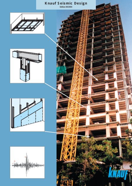
<strong>Knauf</strong> <strong>Seismic</strong> <strong>Design</strong><br />
Edition 08/2004
Earthquakes can cause huge economic<br />
losses. Primarily, however, they also cause<br />
personal distress with deaths, injuries, the<br />
loss of living space, and the devastation of<br />
living conditions.<br />
<strong>Knauf</strong> <strong>Seismic</strong> <strong>Design</strong><br />
Earthquake Safety<br />
with <strong>Knauf</strong> Systems<br />
Most of these losses are set off by buildings<br />
that are unable to resist earthquake<br />
loads.<br />
In order to avoid, or at least reduce these<br />
damages there are three basic principles<br />
related to both cost-effective construction<br />
as well as the earthquake safety of<br />
buildings [1]:<br />
Figure 1: Earthquake-damaged building<br />
1.) In the event of slightly severe earthquakes,<br />
buildings must be able to survive<br />
without damage.<br />
2.) In the event of moderately severe<br />
earthquakes, the damage to the buildings<br />
must be negligible.<br />
3.) In the event of severe earthquakes,<br />
the buildings must be prevented from<br />
collapsing.<br />
Above all, the protection of human life<br />
must be assured by ensuring the options of<br />
survival, escape and rescue in the event of<br />
earthquakes of any severity.<br />
Figure 2: “Soft story effect”<br />
The appropriate literature [2], [3] and<br />
National Standards (DIN 4149, Eurocode<br />
8 - ENV 1998-1 etc.; see pg. 19) provide<br />
constructional guidelines for the technical<br />
implementation of these basic principles.<br />
Going by these mentioned technical guidelines,<br />
<strong>Knauf</strong> Systems present several clear<br />
advantages as compared with solid concrete<br />
and masonry constructions.<br />
2<br />
Figure 3: Collapsed “soft story”
Soft Buildings<br />
Advantages:<br />
Appropriate for rigid subsoil (higher<br />
frequency) due to low natural frequency.<br />
Required ductility is easier to achieve.<br />
An easier calculation procedure.<br />
Disadvantages:<br />
Non-load bearing elements have to<br />
be isolated (movements and deformations,<br />
load distributions).<br />
High stress in junctions due to larger<br />
movements.<br />
Rigid Buildings<br />
Advantages:<br />
Appropriate for soft subsoil due to<br />
high natural frequency.<br />
The junctions are less elaborate due<br />
to smaller movements.<br />
Joints with non-load bearing<br />
construction components with fewer<br />
problems.<br />
Disadvantages:<br />
Higher stress when subsoil is rigid.<br />
Lower ductility.<br />
The calculation procedure is more<br />
complex.<br />
a) floor plan vertical layout<br />
Structural Basics<br />
1.) Rigidity of load-bearing structure.<br />
A decision in favor of or against soft or rigid<br />
structures has to take the conditions of<br />
the foundation soil into consideration.<br />
Rigid structures should be founded on<br />
soft subsoil, and soft structures should be<br />
founded on rigid subsoil in order to avoid<br />
undesired large stresses caused by the effects<br />
of resonance.<br />
2.) Ensure a steady and symmetrical distribution<br />
of weight and rigidity in the vertical<br />
and horizontal layout taking non-load bearing<br />
construction components into consideration,<br />
in order to avoid higher torsion-related<br />
stress (fi gure 4).<br />
3.) Avoid “top heaviness” of the vertical layout<br />
related to both weight (including nonload<br />
bearing components) and rigidity. In a<br />
majority of cases, the “soft story effect” is responsible<br />
for the collapse of buildings in the<br />
event of an earthquake (fi gures 2 and 3).<br />
b) floor plan vertical layout<br />
Figure 4: a)Unfavourable layouts b) Improvement through structural subdivision<br />
4.) Use ductile materials for non-load bearing<br />
construction components. Avoid brittle<br />
materials that display unfavorable behavioral<br />
patterns in the case of a collapse (unannounced<br />
collapses, brittle fraction). They<br />
could thus lead to undesired load distribution<br />
when not installed properly, with higher<br />
destruction effects when compared with<br />
more ductile materials (fi gure 5).<br />
The objective should be to implement<br />
these basic rules in the construction of new<br />
buildings as well as in the improvement of<br />
Figure 5: Damage caused by collapsing masonry<br />
existing buildings.<br />
3
<strong>Seismic</strong> Zones<br />
Every country has different seismic zones<br />
that refer to nominal horizontal ground accelerations<br />
depending on the regional seismic activity<br />
(table 2).<br />
In table 1 the zones have been allocated to<br />
the internationally recognized EMS-98-scale<br />
(table 1) in order to ensure the international<br />
comparability of national guidelines. With 12<br />
intensity classifi cations this scale specifi es<br />
earthquake intensities based on their effects on<br />
human beings and buildings. It is a better scale<br />
than the well-known Richter scale that provides<br />
us with the energy release rate at the epicenter<br />
of earthquakes. The effect on buildings, however,<br />
depends on the epicenter‘s distance to the<br />
earth’s surface.<br />
The values stated in table 2 are the nominal<br />
ground accelerations. For calculation purposes,<br />
other mathematical factors such as behavioral,<br />
soil group, and building classifi cation factors<br />
have to be additionally applied as set down in<br />
the national standards.<br />
Usually, the vertical acceleration is neglected.<br />
It can, however, amount to up to 50 % of the horizontal<br />
acceleration. In individual cases it might<br />
have to be taken into consideration for certain<br />
construction components.<br />
Tabelle 1: European Macroseismic Scale 1998 EMS-98 [5]<br />
EMS<br />
intensity<br />
Definition Description of typical observed effects (abstracted)<br />
I Not felt Not felt.<br />
II Scarcely felt Felt only by very few individual people at rest in houses.<br />
III Weak Felt indoors by a few people. People at rest feel a swaying<br />
or light trembling.<br />
IV<br />
Largely<br />
observed<br />
Felt indoors by many people, outdoors by very few. A<br />
few people are awakened. Windows, doors and dishes<br />
rattle.<br />
V Strong Felt indoors by most, outdoors by few. Many sleeping<br />
people awake. A few are frightened. Buildings tremble<br />
throughout. Hanging objects swing considerably. Small<br />
objects are shifted. Doors and windows swing open or<br />
shut.<br />
VI<br />
Slightly<br />
damaging<br />
Many people are frightened and run outdoors. Some objects<br />
fall. Many houses suffer slight non-structural damage<br />
like hair-line cracks and fall of small pieces of plaster.<br />
VII Damaging Most people are frightened and run outdoors. Furniture<br />
is shifted and objects fall from shelves in large numbers.<br />
Many well built ordinary buildings suffer moderate damage:<br />
small cracks in walls, fall of plaster, parts of chimneys<br />
fall down; older buildings may show large cracks in walls<br />
and failure of fi ll-in walls.<br />
VIII<br />
Heavily<br />
damaging<br />
Many people fi nd it diffi cult to stand. Many houses have<br />
large cracks in walls. A few well built ordinary buildings<br />
show serious failure of walls, while weak older structures<br />
may collapse.<br />
IX Destructive General panic. Many weak constructions collapse. Even<br />
well built ordinary buildings show very heavy damage:<br />
serious failure of walls and partial structural failure.<br />
X<br />
Very<br />
destructive<br />
Many ordinary well built buildings collapse.<br />
XI Devastating Most ordinary well built buildings collapse, even some<br />
with good earthquake resistant design are destroyed.<br />
XII<br />
Completely<br />
devastating<br />
Almost all buildings are destroyed.<br />
4
<strong>Knauf</strong> <strong>Seismic</strong> <strong>Design</strong><br />
<strong>Seismic</strong> Zones and <strong>Seismic</strong> Intensities<br />
Table 2: <strong>Seismic</strong> zones in selected countries<br />
EMS-<br />
98-<br />
Scale<br />
Appropriate<br />
horizontal<br />
ground<br />
acceleration<br />
Argentina<br />
INPRES-CIRSOC<br />
103 Part I<br />
1991<br />
Austria<br />
ÖNORM B4015<br />
2002<br />
Bulgaria<br />
Code for<br />
seismic <strong>Design</strong><br />
1987<br />
Chile<br />
NCH 433 Of 96<br />
1996<br />
China<br />
GB/T177742<br />
1999<br />
CIS<br />
SNiP II-7-81*<br />
2000<br />
Germany<br />
DIN 4149-1<br />
1981<br />
a [m/s²] Zone a 0<br />
[m/s²] Zone a 0<br />
[m/s²] Zone a 0<br />
[m/s²] Zone a 0<br />
[m/s²] Zone a 0<br />
[m/s²] Zone a 0<br />
[m/s²] Zone a 0<br />
[m/s²]<br />
I < 0.01<br />
II 0.01-0.025<br />
III 0.025-0.05<br />
0 0-0.35<br />
A 0<br />
IV 0.05-0.12 0 ≤ 0.39<br />
0<br />
V 0.12 -<br />
0.25<br />
1 1.96<br />
0.22-0.44<br />
VI 0.25 -<br />
VI 0.49<br />
1 0.35-0.50<br />
0 0<br />
0.50<br />
1 0.40-0.98 0.45-0.89<br />
VII 0.50 - 2 0.50-0.75 VII 0.98<br />
1 0.25<br />
1.0<br />
1.0<br />
3 0.75-1.00<br />
2 0.40<br />
2 0.99-1.77<br />
0.90-1.77<br />
VIII 1.0 -<br />
VIII 1.47<br />
3 0.65<br />
2.0<br />
2.0<br />
4 1.00<br />
3 1.78-2.45 2 1.96-2.94 1.78-3.53<br />
IX 2.0- IX 2.65<br />
4.0<br />
4.0 4 2.46-3.43 3 2.94-3.92<br />
3.54-7.07<br />
X 4.0 -<br />
4 >1.00<br />
8.0<br />
XI 8.0 -<br />
16.0<br />
XII > 16.0<br />
7.08-<br />
14.14<br />
EMS- Appropriate Greece Iran<br />
Italy<br />
Romania Switzerland Turkey<br />
98- horizontal EAK 2000 Document technical government<br />
order<br />
P 100-92 SIA 261 ABYYHY<br />
Scale ground<br />
No. 2800 2 nd ed.<br />
acceleration 2000<br />
1999<br />
2004<br />
1992<br />
2003<br />
1998<br />
a [m/s²] Zone a 0<br />
[m/s²] Zone a 0<br />
[m/s²] Zone a 0<br />
[m/s²] Zone a 0<br />
[m/s²] Zone a 0<br />
[m/s²] Zone a 0<br />
[m/s²]<br />
I < 0.01<br />
II 0.01-0.025<br />
III 0.025-0.05<br />
IV 0.05-0.12<br />
4 ≤ 0.49<br />
V 0.12 -<br />
0.25<br />
4 1.96<br />
VI 0.25 -<br />
0.50<br />
VII 0.50 -<br />
1 0.6<br />
F 0.78<br />
1.0 3 0.5-1.47<br />
2 1.0<br />
VIII 1.0 - I 1.18 E 1.18 3a 1.3<br />
4 ≤1.0<br />
2.0 II 1.57<br />
D 1.57 3b 1.6<br />
2 1.47-2.45<br />
IX 2.0<br />
3 2.45 C 1.96 3 2.0<br />
III 2.53<br />
- 2 2.94<br />
B 2.45 2 3.0<br />
4.0 IV 3.53 1 3.43 A 3.14<br />
X 4.0 -<br />
1 4.0<br />
8.0<br />
1 > 2.45<br />
XI 8.0 -<br />
16.0<br />
XII > 16.0<br />
5
Types of Collapse and Damage<br />
The collapse of buildings can either be<br />
global or local. The term local implies that<br />
only a part of the load-bearing structure or<br />
a single construction component collapses.<br />
When a collapse is termed global, the<br />
whole structure is considered to have been<br />
destroyed.<br />
Cracks, plastic displacements etc. are<br />
damages which can cause the loss of a<br />
building’s usability, as well.<br />
Apart from basic “under dimensioning,”<br />
the following types of collapses may occur<br />
due to errors in either the conception or<br />
execution of buildings:<br />
The “soft story effect” (fi gures 2 and 3)<br />
occurs due to a story with little rigidity (for<br />
architectural reasons mostly the ground<br />
fl oor) that attracts stresses from rigid stories<br />
and subsequently collapses. It is the<br />
weakest part of the structure. Strictly speaking,<br />
it is a local collapse, but it can cause<br />
a global collapse and lead to the ultimate<br />
loss of the building.<br />
The “short columns effect” (fi gure<br />
7) is caused by undesired load swaps into<br />
construction components that are not divided<br />
well enough from the load-bearing<br />
structure. The reason is the subsequent increase<br />
of rigidity through masonry and the<br />
following higher seismic load due to the<br />
shortening of the swing period.<br />
The sudden and unannounced collapse<br />
of infill masonry (fi gures 6 and 8) is extremely<br />
dangerous to people in the building.<br />
It can even lead to a complete collapse<br />
of the whole building (fi gure 5). The reason<br />
is the higher rigidity of infi ll masonry,<br />
as compared with the softer columns, that<br />
causes the swapping of loads into the masonry.<br />
The brittle material collapses in an<br />
explosion-like manner.<br />
6<br />
Figure 6: Collapse of infi ll masonry<br />
Figure 7: Short columns effect<br />
Figure 8: Collapsed infi ll masonry
<strong>Knauf</strong> <strong>Seismic</strong> <strong>Design</strong><br />
Less Weight<br />
- Less Trouble<br />
Example according to<br />
Eurocode 8 (EN 1998: 1997): (figure 9)<br />
● 7-story residential building<br />
● Reinforced skeleton construction<br />
● Total height: 19 m<br />
● Ground area 18 x 12 m<br />
● Reference value of horizontal ground<br />
acceleration: 0.4 g<br />
● Total weight of load-bearing compo -<br />
nents: 1095 t<br />
● Total weight of walls (masonry incl.<br />
plaster = 200 kg/m² interior / 240 kg/m²<br />
exterior)): 518 t<br />
● Total weight of walls<br />
(interior: <strong>Knauf</strong> W112, 49 kg/m²,<br />
exterior: Aquapanel, 42 kg/m²) : 109 t<br />
● Total weight of building:<br />
Figure 9: Skeletal frame of a 7-story building<br />
Table 3: Load values for cited example<br />
Interior Walls<br />
Exterior Walls<br />
Total vertical load for<br />
earthquake calculation<br />
Masonry<br />
(200 kg/m²)<br />
(240 kg/m²)<br />
<strong>Knauf</strong> Systems<br />
W112<br />
(49 kg/m²)<br />
Aquapanel<br />
(42 kg/m²)<br />
17.8 MN 13.7 MN<br />
with masonry: 1614 t<br />
with <strong>Knauf</strong> systems: 1204 t<br />
(25 % less weight when <strong>Knauf</strong> Systems<br />
are used instead of masonry)<br />
By calculating the earthquake loads<br />
according to Eurocode 8 it can be determined<br />
that these loads are decreased by<br />
Total horizontal<br />
earthquake load<br />
according to EC 8<br />
at a 0<br />
= 0.4 g<br />
4.0 MN 3.1 MN<br />
approx. 23 % when using <strong>Knauf</strong> W112 for<br />
interior partitions and <strong>Knauf</strong> Aquapanel for<br />
exterior walls.<br />
Ratio 100 % 77 %<br />
A more economic dimensioning of the<br />
expensive reinforced concrete structure<br />
thus becomes possible for both static and<br />
earthquake loads.<br />
Additionally, earthquake safety is<br />
improved due to the better deformation and<br />
collapse behavior of drywall constructions<br />
in the event of an earthquake.<br />
7
Advantages<br />
●Low dead load ( ˆ= lower earthquake<br />
loads)<br />
● Sound insulation<br />
● Drywall materials are a major<br />
advantage in remodelling and<br />
renovation<br />
<strong>Knauf</strong> <strong>Seismic</strong> <strong>Design</strong><br />
Advantages of <strong>Knauf</strong><br />
Drywall Systems as<br />
Compared with Solid<br />
Constructions<br />
● Fire protection (ceilings, panelling<br />
of beams and columns)<br />
● Flexible for rededications<br />
● Ductile behavior of deformation<br />
and collapse; no unannounced<br />
collapse<br />
● Preservation of enclosing function<br />
even after possible collapse<br />
8<br />
Figure 10: <strong>Knauf</strong> suspended ceiling D112
<strong>Knauf</strong> <strong>Seismic</strong> <strong>Design</strong><br />
Applications<br />
Non-load bearing Partitions /<br />
Suspended Ceilings (pp. 10 / 12)<br />
As construction components, the wellknown<br />
<strong>Knauf</strong> partitions and ceiling systems<br />
are earthquake proof by themselves [6].<br />
Additionally, they add a considerable<br />
amount of earthquake safety to a building<br />
based on the benefi ts mentioned earlier in<br />
this brochure.<br />
Application is possible both in new<br />
buildings as well as for the retrofi tting or<br />
renovation of existing buildings.<br />
Shear Walls (pg. 14)<br />
Figure 11: <strong>Knauf</strong> partition W112<br />
<strong>Knauf</strong> drywall partitions can bear horizontal<br />
shear forces like wind and earthquake<br />
loads if they are adapted to brace<br />
load-bearing structures. With that, the<br />
advantages of <strong>Knauf</strong> drywall partitions can<br />
be exploited for walls in new buildings and<br />
in the case of renovation and retrofi ttings<br />
with structural requirements.<br />
Bracing Wall and Ceiling Panels for<br />
Steel Framework Buildings (pg. 16)<br />
Prefabricated or on-site fabricated wall<br />
and ceiling panels can be used for new<br />
steel framework buildings.<br />
These panels link the advantages of dry<br />
construction systems with a highly effective<br />
execution process.<br />
The <strong>Knauf</strong> partner company, Danogips,<br />
offers the SBS (Steel Building System)<br />
which will shortly be adapted for use in<br />
Figure 12: The Danogips SBS (Steel Building System)<br />
earthquake endangered buildings.<br />
9
The main advantages of <strong>Knauf</strong> nonload<br />
bearing partitions are the reduction<br />
of construction weight (see table 3, page<br />
7 and table 4) and the ductile behavior of<br />
deformation. The dead load decrease of<br />
non-load bearing construction components<br />
leads to a massive reduction of loads in the<br />
event of an earthquake.<br />
The most ideal application of <strong>Knauf</strong><br />
partitions in connection with earthquake<br />
safety is their use as infi ll walls for skeleton<br />
constructions.<br />
The brittle and comparatively rigid<br />
deformation behavioral patterns of the<br />
infi ll masonry used generally causes load<br />
transfer with dangerous, explosion-like and<br />
<strong>Knauf</strong> <strong>Seismic</strong> <strong>Design</strong><br />
Non-load bearing<br />
Partitions<br />
Table 4: Weight comparison of infill masonry and <strong>Knauf</strong> Drywall Systems W111/ W112<br />
Weight Reduction<br />
1 m² masonry d = 11.5 cm;<br />
Weight per unit area: approx. 145 kg/m²<br />
1 m² metal stud partition, single layer;<br />
Weight per unit area: approx. 25 kg/m²<br />
1 m² metal stud partition, double layer;<br />
Weight per unit area: approx. 50 kg/m²<br />
→ Weight reduction by 65 % to 83 %<br />
unannounced collapse that can even lead<br />
Table 5: Stress resultants from lateral horizontal loads<br />
System<br />
W111<br />
d = 100 mm<br />
W112<br />
d = 125 mm<br />
Horizontal<br />
acceleration<br />
0.5 g<br />
(4.9 m/s²)<br />
Max.<br />
shift<br />
[mm]<br />
Maximum<br />
bending<br />
moment<br />
[kNm]<br />
2.5 - 14 0.1 - 0.3 2.0<br />
11.6 - 25 0.3 - 0.6 2.6<br />
Bending<br />
moment<br />
capacity<br />
[kNm]<br />
to the total collapse of the whole building.<br />
Even when highly deformed, drywall<br />
partitions maintain their enclosing function<br />
and do not collapse completely. [7]<br />
According to the “Report of Earthquake<br />
Proof Execution of Partitions and Suspended<br />
Ceilings” by Dr. Rainer Flesch of the<br />
“Bundesforschungs- und Prüfzentrum Arsenal”<br />
(Federal Research and Test Centre<br />
Arsenal) [6], <strong>Knauf</strong> metal stud partitions<br />
can effectively resist and absorb lateral<br />
loads caused by earthquake acceleration<br />
and their own weight.<br />
Table 5 shows calculated stress resultants<br />
for a lateral horizontal acceleration of<br />
2.5 m h 3.5 m<br />
U ; V´<br />
0.5 g on <strong>Knauf</strong> partitions W111 and W112.<br />
2.5 m l 15.0 m<br />
Figure 13: Lateral horizontal loading<br />
10
Table 6: Maximum Resistible Horizontal Acceleration<br />
<strong>Knauf</strong> gypsum<br />
board partition<br />
system<br />
W111<br />
single layer<br />
(1x12.5 mm)<br />
25 kg/m²<br />
W112<br />
double layer<br />
(2x12.5 mm)<br />
50 kg/m²<br />
Size of stud /<br />
thickness of wall<br />
[mm] / [mm]<br />
Maximum<br />
wall height<br />
[m]<br />
Bending<br />
moment<br />
capacity<br />
[kNm]<br />
50 / 75 3.0 1.5 ≤ 5.4 g<br />
75 / 100 4.5 2.0 ≤ 3.1 g<br />
100 / 125 5.0 2.5 ≤ 3.2 g<br />
50 / 100 4.0 2.0 ≤ 2.0 g<br />
75 / 125 5.5 2.6 ≤ 1.4 g<br />
100 / 150 6.0 3.2 ≤ 1.4 g<br />
Maximum resistible<br />
horizontal<br />
acceleration<br />
Values for the maximum acceptable horizontal<br />
acceleration based on load capacities<br />
according to [8] are stated in table 6.<br />
However, going by the following assumption<br />
horizontal in-plane loads caused by<br />
story shift cannot be borne by these partitions<br />
[6] (fi gure 14).<br />
With an assumed story shift of 1 % to 1.5 %,<br />
a maximum height of wall of 3.5 m, and the<br />
resulting story shift of ∆l = 3.5 to 5.3 cm,<br />
F M<br />
l<br />
the resulting stresses cannot be absorbed<br />
by the partition without cracks developing.<br />
The enclosing function would still be retained,<br />
but a big enough joint is necessary<br />
h 3.5 m<br />
in order to absorb the deformation of the<br />
structure.<br />
2.5 m l 15.0 m<br />
Figure 14: Horizontal in-plane load<br />
30 mm<br />
V' x<br />
A viable solution according to the example<br />
cited above is shown in fi gure 15.<br />
In individual cases the necessary size of<br />
the joint has to be determined exactly through<br />
a calculation of the expected deformation.<br />
U Runner (d = 1.0 mm)<br />
spacing of dowels = 0.5 m<br />
Figure 15: Detail of deformation joint<br />
Figure 16: Statical separation of non-load bearing partitions<br />
11
<strong>Knauf</strong> suspended ceilings keep the dead<br />
load of non-load bearing construction components<br />
low and fulfi l the enhanced building<br />
requirements of sound insulation, fi re protection<br />
and thermal insulation. Furthermore,<br />
<strong>Knauf</strong> suspended ceiling systems create<br />
additional space for service or sanitary<br />
installations.<br />
<strong>Knauf</strong> <strong>Seismic</strong> <strong>Design</strong><br />
Suspended Ceilings<br />
Table 7: Load values in ceiling studs with vertical acceleration of 0.5 g<br />
Suspended ceiling<br />
Gypsum<br />
board layer<br />
layout<br />
[m]<br />
Maximum bending<br />
moment<br />
[kNm]<br />
Maximum shift<br />
[mm]<br />
Breaking<br />
moment of<br />
channels [kNm]<br />
Suspension Suspension Suspension<br />
soft rigid soft rigid soft rigid<br />
The behavior of suspended ceilings in the<br />
event of an earthquake also has been an<br />
object of investigation in the report mentioned<br />
earlier [6].<br />
Different variations were analyzed in order<br />
to detect any links between behavior under<br />
dynamic loads, the rigidity of the suspension,<br />
and the layout (table 7, fi gure 17).<br />
The rigidity of the suspension is infl u-<br />
enced by the number, the alignment and<br />
single<br />
(1 x 12.5 mm)<br />
12.5 kg/m²<br />
double<br />
(2 x 12.5 mm)<br />
25 kg/m²<br />
3 x 5<br />
0.02 22.3<br />
0.20<br />
7 x 15<br />
27<br />
0.005<br />
10 x 10 0.15 25<br />
3 x 5<br />
0.05 44 7.4<br />
7 x 15 0.35<br />
50 7.5<br />
0.015<br />
10 x 10 48 8.0<br />
V' (0.5 g) z<br />
3.0 0.186 0.186<br />
0.222 0.222<br />
the rigidity of the suspenders. (fi gure 17,<br />
table 8).<br />
The results show that a rigid suspension<br />
is better than a soft suspension when dynamic<br />
loads are applied.<br />
Due to the effects of resonance, both defl<br />
ection and the bending moment are signifi -<br />
cantly lower with rigid suspensions as compared<br />
with soft suspensions.<br />
The bending moment capacity is reached<br />
or partially overstepped with a soft suspension.<br />
Another remarkable characteristic is that<br />
the layout does not have a signifi cant infl u-<br />
ence on the defl ection. Single layer board<br />
application is preferable due to the lower<br />
weight. However, this is not always possib-<br />
1.25 m<br />
1.25 m<br />
1.25 m 1.25 m<br />
"soft" suspension<br />
suspenders at every 2nd crossing<br />
0.50 m<br />
"rigid" suspension<br />
suspenders at each crossing<br />
CD channel<br />
suspended CD channel<br />
CD channel<br />
suspended CD channel<br />
le as fi re safety requirements might have to<br />
be taken into consideration.<br />
0.50 m<br />
Figure 17: Constructional set-up for rigid or soft suspensions<br />
12
Table 8: <strong>Knauf</strong> Suspenders<br />
0.25 kN<br />
Anchor Fix<br />
0.4 kN<br />
Nonius Hanger<br />
0,4 kN <strong>Knauf</strong><br />
Universal Bracket<br />
The following constructional demands<br />
have to be taken into consideration for application:<br />
● Place suspenders as close as possible<br />
to the cross-alignment points of the<br />
104 200<br />
270<br />
Rigidity [kN/m]<br />
channels.<br />
● The connectors have to be screwed together<br />
with channels and suspenders.<br />
10 mm<br />
10 mm<br />
12.5 mm 12.5 mm<br />
● The suspension height should be as<br />
short as possible.<br />
● The weight should be as low as possible<br />
to reduce earthquake loads. One<br />
layer is better than two layers.<br />
10 mm<br />
10 mm<br />
25 mm<br />
● The lateral connection should slide<br />
Rigid suspension<br />
● do not fasten cladding to<br />
perimeter channel<br />
Figure 18 :Layouts<br />
Soft suspension<br />
● single layer cladding<br />
● square layout<br />
● connection to perimeter<br />
channel on one side<br />
horizontally but be vertically fixed.<br />
● The edge distance of first channel grid<br />
from flanking component should be<br />
approx. 100 mm.<br />
Construction examples can be seen in fi -<br />
load-bearing structure<br />
gures 19 and 20.<br />
The use of the soft suspension as shown<br />
open joint<br />
suspended ceiling<br />
mold<br />
Figure 19: Section of suspended ceiling<br />
horizontal<br />
fixing<br />
in fi gure 17 and table 7 is limited. In buildings<br />
classifi ed as I and II according to Eurocode<br />
8-1-2 and areas with high seismic<br />
activity soft suspension systems cannot be<br />
used. Even for building classifi cation III the<br />
Connection without<br />
fire protection requirements<br />
● shifting substructure<br />
Figure 20: Joint details<br />
Connection with<br />
1.5 hr fire protection<br />
● Shifting substructure<br />
● Rigid connection of cladding<br />
(tightness)<br />
● Alternative: expanding<br />
sealing strip<br />
(with / without mold)<br />
use is limited. Furthermore, constructional<br />
demands according to fi gure 18 should also<br />
be taken into account.<br />
All elements in the plenum (above the<br />
suspended ceilings) that are not part of<br />
the suspended ceiling must have a separate<br />
suspension and are not allowed to apply<br />
their weight on any component of the suspended<br />
ceiling.<br />
This requirement should be fulfi lled both<br />
for earthquake safety purposes and for fi re<br />
protection reasons.<br />
13
<strong>Knauf</strong> partitions such as the wooden panel<br />
partitions and the metal stud partitions<br />
can be used as shear walls for horizontal<br />
loads from wind and earthquakes for both<br />
new buildings and the renovation of buildings.<br />
Shear walls are well-known building<br />
methods in the USA and New Zealand where<br />
wooden constructions are mainly used.<br />
The values and application guidelines<br />
of non-load bearing partitions can be applied<br />
to lateral loads. No resonance effects<br />
should be expected for in-plane loads due<br />
to the high natural frequency in case of<br />
shear loads.<br />
Consequently, no dynamic effects need<br />
to be taken into consideration, and structural<br />
loads can be assumed accordingly.<br />
Table 9 shows the permissible in-plane<br />
<strong>Knauf</strong> <strong>Seismic</strong> <strong>Design</strong><br />
Shear Walls<br />
Table 9: Horizontal load capacity of wooden panel partitions according to<br />
„Allgemeinen bauaufsichtlichen Zulassungen“ (General Building Supervisory Permits)<br />
Z-9.1-339 (<strong>Knauf</strong> gypsum fiber boards) and Z-9.1-199 (<strong>Knauf</strong> gypsum boards)<br />
Cladding<br />
both sides<br />
one side<br />
Stud<br />
spacing<br />
Standard<br />
b S<br />
Spacing<br />
of nails /<br />
staples<br />
e R<br />
Gypsum fiber<br />
boards perm. F H<br />
in<br />
kN for panel height<br />
h in m<br />
Gypsum boards<br />
perm. F H<br />
in kN<br />
for panel height<br />
h in m<br />
mm mm ≤ 2.60 ≤ 3.00 ≤ 2.60 ≤ 3.00<br />
600-625<br />
1200-<br />
1250<br />
1200-<br />
1250<br />
min. 50 3.3<br />
max. 75 3.3<br />
max. 150 1.3<br />
min. 50 6.0 5.5<br />
max. 75 7.5 6.3<br />
max. 150 2.7 2.7<br />
min. 50 3.3<br />
max. 75 4.4 2.8<br />
max. 150 1.5<br />
1)<br />
Linear interpolation is allowed for values of perm. F H<br />
between e R<br />
= 50 mm and 150 mm, likewise between h = 2.60 m and<br />
3.0 m.<br />
loads for <strong>Knauf</strong> wooden panel partitions<br />
according to the “Allgemeine bauaufsichtliche<br />
Zulassung Z-9.1-199” (The General<br />
Building Supervisory Permit) [10] (Further<br />
information about reduction factors is cited<br />
Half panel<br />
F H<br />
e R<br />
F V<br />
Full size panel<br />
e R<br />
F V<br />
here).<br />
The German Standard for wooden<br />
constructions DIN 1052 (08/2004) includes<br />
detailed information for the dimensioning<br />
of wooden panel partitions with gypsum<br />
boards and in-plane loading.<br />
Bernd Naujoks (TU Darmstadt, Institut für<br />
Stahlbau und Werkstoffmechanik/ Technical<br />
R<br />
e R<br />
R<br />
e R<br />
h 2600 mm<br />
F H<br />
R M R<br />
e R<br />
max. e M = 150<br />
e R<br />
h 3000 mm<br />
(only with double sided cladding and b 1200)<br />
s<br />
University of Darmstadt) did a report on me-<br />
e R<br />
e R<br />
tal stud constructions, “Tragverhalten von<br />
Wandtafeln mit Kaltprofi len unter horizontalen<br />
Lasten“ [11]. Among other tests me-<br />
Z A<br />
b = 600 to 625 mm<br />
s<br />
Z A<br />
bs<br />
625 to 1250 mm<br />
tal stud partitions with gypsum fi ber board<br />
Figure 21: Loading set-up for Table 9<br />
application under in-plane load (horizontal,<br />
and combined with vertical load) ...<br />
Continuation on page 15<br />
14
Table 10: Collapse loads for metal stud shear walls from [9]<br />
Cladding 1 Cladding 2 Spacing of<br />
screws s r<br />
[mm] at<br />
perimeter<br />
Horizontal<br />
load F H<br />
at<br />
collapse<br />
[kN]<br />
Vertical<br />
load F V<br />
at<br />
collapse<br />
[kN]<br />
Number<br />
of tests<br />
Continuation from page 14<br />
...by varying the spacing of the screw<br />
attachment were tested for this research<br />
paper. A dimensioning calculation has been<br />
Gypsum<br />
fi ber board<br />
(e.g. <strong>Knauf</strong><br />
Vidiwall)<br />
Cementous<br />
fi ber board<br />
(e.g. <strong>Knauf</strong><br />
Aquapanel)<br />
Gypsum<br />
fi ber<br />
board<br />
(e.g. <strong>Knauf</strong><br />
Vidiwall)<br />
100 39.8 0 3<br />
150 33.1 0 3<br />
150 43.6 0 3<br />
Chipboard 150 39.9 0 3<br />
Trapezoid<br />
metal sheet<br />
172/150 39.0 0 3<br />
none 200 12.2 30 1<br />
also developed by Bernd Naujoks.<br />
The test results shown in table 10 are not<br />
dimensioning values ; these are breaking<br />
loads with defi ned collapse criteria without<br />
statistical consideration or safety factors.<br />
The collapse of wooden panel partitions is<br />
usually caused by the connections between<br />
the board and the wooden framing members.<br />
For metal stud partitions, however, the col-<br />
1<br />
3<br />
1<br />
3<br />
1<br />
3<br />
F V<br />
F V<br />
F V<br />
F H<br />
lapse can be caused by the buckling of the<br />
lower end of the pressure-impacted stud if<br />
the spacing of screws is small enough. [11]<br />
Additional reinforcements in this area, e.g.<br />
corner bracing components increase the<br />
load capacity of metal stud shear walls.<br />
260 cm<br />
It should, however, be borne in mind that<br />
the fi gures stated do not take into account<br />
Figure 22: Load set-up for Table 10<br />
125 cm<br />
any effects of creeping under permanent<br />
loads. Hence, it should be ensured that no<br />
permanent loads occur through plastic deformations<br />
or the restraint of fl anking components.<br />
Drywall shear walls can be used up to 5<br />
stories.<br />
Table 11: Comparison of shear capacity of masonry walls and<br />
<strong>Knauf</strong> shear walls<br />
Wall type<br />
(l=5m, h=3m)<br />
Total capacity<br />
kN<br />
Capacity<br />
kN/m<br />
Weight of wall<br />
kg/m²<br />
120 mm masonry 1) 9 1.8 194<br />
180 mm masonry 1) 15 3.0 299<br />
240 mm masonry 1) 20 4.0 405<br />
≥ 75 mm <strong>Knauf</strong> W 111 2) 12 2.4 25<br />
≥ 100 mm <strong>Knauf</strong> W 112 2) 19 3.8 50<br />
1)<br />
Strength of bricks = 15.0 N/mm²<br />
2)<br />
Studs c/c 600 mm. Screw spacing around perimeter 200 mm in both layers.<br />
In table 11 the shear load capacity of masonry<br />
and <strong>Knauf</strong> shear walls is stated for<br />
walls 3 m high and 5 m long.<br />
It shows that the shear capacity of <strong>Knauf</strong><br />
partitions is comparable to the capacity of<br />
conventional masonry with a signifi cantly<br />
lower weight.<br />
Material values for dimensioning are stated<br />
in tables 12 and 13, pg 17.<br />
15
The <strong>Knauf</strong> partner company, Danogips,<br />
offers the SBS (Steel Building System) as<br />
an effi cient constructional option for new<br />
steel framework buildings.<br />
The wall and ceiling panels used in this<br />
<strong>Knauf</strong> <strong>Seismic</strong> <strong>Design</strong><br />
Bracing Wall and<br />
Ceiling Panels<br />
system are prefabricated to various degrees<br />
and can bear horizontal loads from<br />
wind and earthquakes.<br />
To date the system can only be used for<br />
static loads. <strong>Knauf</strong> and Danogips are currently<br />
working together to adapt it for use<br />
under dynamic loads, such as in earthquake<br />
endangered areas, in the next few<br />
months.<br />
All the previously mentioned advantages<br />
of drywall constructions can be applied to<br />
the SBS. Additionally, there is the cost-saving<br />
option on expensive reinforced concrete<br />
or steel constructions as the SBS system<br />
is able to to bear loads.<br />
Figure 23: Facade with Danogips SBS (Steel Building System)<br />
Figure 24: Ceiling panel<br />
16
<strong>Knauf</strong> <strong>Seismic</strong> <strong>Design</strong><br />
Material Values<br />
Table 12:<br />
Shear capacity [kN] of connection of cladding to metal<br />
stud (0.6 mm) per TN drywall screw in kN<br />
Gypsum board<br />
according to EN 520<br />
Screw in<br />
1 st layer<br />
Screw in<br />
2 nd layer<br />
12.5 mm Type E 0.25 0.14<br />
The material data according to DIN 1052<br />
(08/2004) (table 13) and the shear capacities<br />
of the screw connectors (table 12) as<br />
determined by Danogips can be used as dimensioning<br />
values for metal stud partitions<br />
with shear load. Load capacity values for<br />
<strong>Knauf</strong> Systems will be available shortly.<br />
12.5 mm Type F 0.25 0.14<br />
12.5 mm Type A 0.25 0.14<br />
12.5 mm Type I 0.30 0.17<br />
15 mm Type F 0.30 0.17<br />
Table 13: Characteristic values of rigidity and strength for gypsum boards according to DIN 1052 (08/2004) in N/mm²<br />
Load direction Value Gypsum Board GKB/GKBI<br />
d [mm]<br />
Gypsum Board GKB/GKBI<br />
d [mm]<br />
12.5 15 18 12.5 15 18<br />
Gross Density ρ k<br />
[kg/m³] 680 680 680 800 800 800<br />
Shear load Shear Modulus G mean<br />
1)<br />
700 700 700 700 700 700<br />
Shear Strength f v,k<br />
1.0 1.0 1.0 1.0 1.0 1.0<br />
Transverse direction E Modulus E mean<br />
1)<br />
1000 1000 1000 1000 1000 1000<br />
Flexural Strength f m,k<br />
2.0 1.7 1.4 2.0 1.7 1.4<br />
Compressive Strength f c,k<br />
4.2 4.2 4.2 4.8 4.8 4.8<br />
Tensile Strength f t,k<br />
0.7 0.7 0.7 0.7 0.7 0.7<br />
Longitudinal direction E Modulus E mean<br />
1)<br />
1200 1200 1200 1200 1200 1200<br />
Flexural Strength f m,k<br />
4.0 3.8 3.6 4.0 3.8 3.6<br />
Compressive Strength f c,k<br />
3.5 3.5 3.5 5.5 5.5 5.5<br />
Tensile Strength f t,k<br />
1.7 1.4 1.1 1.7 1.4 1.1<br />
Lateral Load Compressive Strength f c,k<br />
3.5 3.5 3.5 5.5 5.5 5.5<br />
Transverse direction E Modulus E mean<br />
1)<br />
2200 2200 2200 2200 2200 2200<br />
Flexural Strength f m,k<br />
2.0 1.8 1.5 2.0 1.8 1.5<br />
Longitudinal direction E Modulus E mean<br />
1)<br />
2800 2800 2800 2800 2800 2800<br />
Flexural Strength f m,k<br />
6.5 5.4 4.2 6.5 5.4 4.2<br />
1)<br />
For the characteristic rigidity values E 05<br />
and G 05<br />
, use E 05<br />
= 0.5 • E mean<br />
G 05<br />
= 0,9 • G mean<br />
for calculation.<br />
17
[8] Naujoks, Bernd „Tragverhalten von<br />
Wandtafeln mit Kaltprofi len unter horizontalen<br />
und vertikalen Lasten“, Veröffentlichungen<br />
des Instituts für Stahlbau<br />
und Werkstoffmechanik der Technischen<br />
Universität Darmstadt, Heft 66,<br />
2002<br />
[9] Dr.-Ing. Meier-Dörnberg „Erdbebensicherheit<br />
von leichten Trennwänden<br />
- <strong>Knauf</strong> Ständerwände mit Gipsplatten<br />
W111 und W112“, TH Darmstadt, Institut<br />
für Mechanik, 1984<br />
[10] Allgemeines bauaufsichtliches Prüfungszeugnis<br />
„Wände in Holztafelbauart<br />
mit Beplankungen aus KNAUF-<br />
Gipsplatten“, Deutsches Institut für<br />
Bautechnik, 2001<br />
[11] Naujoks, Bernd „Tragverhalten von<br />
Wandtafeln mit Kaltprofi len unter horizontalen<br />
Lasten“, TU Darmstadt, Institut<br />
für Stahlbau und Werkstoffmechanik<br />
2002<br />
References<br />
[1] Univ. Doz. Dr. Rainer Flesch<br />
„Grundlagen des erdbebensicheren<br />
Konstruierens“, Österreichische Ingenieur-<br />
und Architekten-Zeitschrift Heft<br />
9, Jahrgang 131 (1986)<br />
[2] Dowrik, D. J. „Earthquake Resistant<br />
<strong>Design</strong>“, John Wiley & Sons, 1977<br />
[3] Müller, Keintzel „Erdbebensicherung<br />
von Hochbauten“, 2. Aufl ., Wilhelm<br />
Ernst & Sohn, 1985<br />
[4] Rosman, Riko „Erdbebenwiderstandsfähiges<br />
Bauen“, Wilhelm Ernst &<br />
Sohn, 1983<br />
[5] „European Macroseismic Scale 1998<br />
EMS-98“, G. Grünthal, ESC Working<br />
Group „Macroseismic Scales“, 1998<br />
[6] Univ. Doz. Dr. Rainer Flesch „Gutachten<br />
über erdbebensichere Ausführung<br />
von Ständerwänden und Plattendecken“,<br />
Bundesforschungs- und Prüfzentrum<br />
Arsenal (Wien), 1995<br />
[7] Dr. Tschirgin/ Dr. Tscherkaschin „Gutachten<br />
über die Anwendungsmöglichkeit<br />
von Trennwand- und Wandbekleidungskonstruktionen<br />
aus Gips-/<br />
Gipsfaserplatten in Erdbebengebieten“,<br />
Kutscherenko-Forschungsinstitut<br />
„ZNIISK“, 2004<br />
18
Table 14: Selected international standards<br />
International ISO 3010 Basis for design of structures - <strong>Seismic</strong> actions on structures 12/01<br />
Germany<br />
(Pre-standard) DIN V ENV 1998-1-1 Eurocode 8 - <strong>Design</strong> provisions for earthquake resistance of structures - Part 1-1: General rules;<br />
seismic actions and general requirements for structure; German version ENV 1998-1-1:1994<br />
(Pre-standard) DIN V ENV 1998-1-2 Eurocode 8 - <strong>Design</strong> provisions for earthquake resistance of structures - Part 1-2: General rules;<br />
general rules for building; German version ENV 1998-1-2:1994<br />
(Pre-standard) DIN V ENV 1998-1-3 Eurocode 8 - <strong>Design</strong> provisions for earthquake resistance of structures - Part 1-3: General rules;<br />
specifi c rules for various materials and elements; German version ENV 1998-1-3:1995<br />
(Pre-standard) DIN V ENV 1998-1-4 Eurocode 8: <strong>Design</strong> provisions for earthquake resistance of structures - Part 1-4: General rules;<br />
strengthening and repair of buildings; German version ENV 1998-1-4:1996<br />
(Draft standard) DIN 4149 Buildings in German earthquake areas - <strong>Design</strong> loads, analysis and structural design of buildings<br />
DIN 4149-1 Buildings in German Earthquake Zones; <strong>Design</strong> Loads, Dimensioning, <strong>Design</strong> and Construction of Conventional Buildings<br />
DIN 4149-1 Beiblatt 1 Buildings in German earthquake areas; relation of administration areas with earthquake areas<br />
DIN 4149-1/A1 Buildings in German earthquake areas; design loads, analysis and structural design, usual buildings; amendment 1, map<br />
showing earthquake areas<br />
06/97<br />
06/97<br />
06/97<br />
09/99<br />
10/02<br />
04/81<br />
04/81<br />
12/92<br />
France NF P06-013 Earthquake resistant construction rules. Earthquake resistant rules applicable to buildings, called PS 92.<br />
NF P06-013/A1 Earthquake resistant construction rules. Earthquake resistant rules applicable to buildings, called PS 92<br />
XP P06-031-1 Eurocode 8 : <strong>Design</strong> provisions for earthquake resistance of structures and national application document - Part 1-1 : general<br />
rules - <strong>Seismic</strong> actions and requirements for structures.<br />
XP P06-031-2 Eurocode 8 : <strong>Design</strong> provisions for earthquake resistance of structures and national application document - Part 1-2 : general<br />
rules for buildings.<br />
XP P06-031-3 Eurocode 8 - <strong>Design</strong> provisions for earthquake resistance of structures and national application document - Part 1-3 : general<br />
rules - Specifi c rules for various materials and elements.<br />
(Draft standard) P06-033PR Eurocode 8 : <strong>Design</strong> provisions for earthquake resistance of structures - Part 1-4 : general rules - Strengthening<br />
and repair of buildings.<br />
12/95<br />
02/01<br />
12/01<br />
12/00<br />
03/03<br />
Great Britain<br />
(Pre-standard) BS DD ENV 1998-1-1 Eurocode 8: <strong>Design</strong> provisions for earthquake resistance of structures - General rules - <strong>Seismic</strong><br />
actions and general requirements for structures<br />
(Pre-standard) BS DD ENV 1998-1-2 Eurocode 8: <strong>Design</strong> provisions for earthquake resistance of structures - General rules - General rules<br />
for buildings<br />
(Pre-standard) BS DD ENV 1998-1-3 Eurocode 8: <strong>Design</strong> provisions for earthquake resistance of structures - General rules - Specifi c rules<br />
for various materials and elements<br />
(Pre-standard) BS DD ENV 1998-1-4 Eurocode 8: <strong>Design</strong> provisions for earthquake resistance of structures - General rules - Strengthening<br />
and repair of buildings<br />
05/96<br />
05/96<br />
05/96<br />
05/96<br />
CIS SniP II 7-81 Bauen in erdbebengefährdeten Gebieten 2000<br />
Italy D.M.L.P. 24. Januar 1986 Technische Normen für erdbebensichere Gebäude 01/86<br />
Austria<br />
(Draft standard) OENORM EN 1998-1 Eurocode 8: <strong>Design</strong> of structures for earthquake resistance - Part 1: General rules, seismic actions<br />
and rules for buildings<br />
(Pre-standard) OENORM ENV 1998-1-1 Eurocode 8: <strong>Design</strong> provisions for earthquake resistance of structures - Part 1-1: General rules<br />
- <strong>Seismic</strong> actions and general requirements for structures<br />
(Pre-standard) OENORM ENV 1998-1-2 Eurocode 8: <strong>Design</strong> provisions for earthquake resistance of structures - Part 1-2: General rules<br />
- General rules for buildings<br />
(Pre-standard) OENORM ENV 1998-1-3 Eurocode 8: <strong>Design</strong> provisions for earthquake resistance of structures - Part 1-3: General rules<br />
- Specifi c rules for various materials and elements<br />
(Pre-standard) OENORM ENV 1998-1-4 Eurocode 8: <strong>Design</strong> provisions for earthquake resistance of structures - Part 1-4: General rules<br />
- Strengthening and repair of buildings<br />
OENORM B 4015 <strong>Design</strong> loads in building - Accidental actions - <strong>Seismic</strong> actions - General principles and methods of calculation<br />
05/04<br />
06/97<br />
06/97<br />
06/97<br />
12/99<br />
06/02<br />
Switzerland<br />
SIA 260 Basis of structural design<br />
SIA 261 Actions on Structures<br />
SIA 261/1 Actions on Structures - Supplementary Specifi cations<br />
(Pre-standard) SN ENV 1998-1-1 Eurocode 8 - <strong>Design</strong> provisions for earthquake resistance of structures - Part 1-1: General rules; seismic<br />
actions and general requirements for structure<br />
(Pre-standard) SN ENV 1998-1-2 Eurocode 8 - <strong>Design</strong> provisions for earthquake resistance of structures - Part 1-2: General rules; general<br />
rules for building<br />
(Pre-standard) SN ENV 1998-1-3 Eurocode 8 - <strong>Design</strong> provisions for earthquake resistance of structures - Part 1-3: General rules; specifi c<br />
rules for various materials and element<br />
01/03<br />
01/03<br />
01/03<br />
1998<br />
1994<br />
1995<br />
Turkey ABYYHY Specifi cations for Structures to be Built in Disaster Areas Part III - Earthquake Disaster Prevention 07/98<br />
19
<strong>Knauf</strong> Gips KG<br />
Am Bahnhof 7, D-97346 Iphofen<br />
Phone: +49-9323-31-0<br />
Fax: +49-9323-31-277<br />
http://www.knauf.de<br />
e-mail: info@knauf.de<br />
Danogips A/S<br />
Kløvermarksvej 4-6<br />
DK-9500 Hobro<br />
Phone: (+45) 96-573000<br />
Fax: (+45) 96-573001<br />
http://www.danogips.dk<br />
e-mail: info@danogips.dk<br />
<strong>Knauf</strong> AG<br />
Kägenstraße 17<br />
CH-4153 Reinach<br />
Phone: (+41) 61-716-10-10<br />
Fax: (+41) 61-716-10-11<br />
http://www.knauf.ch<br />
e-mail: info@knauf.ch<br />
<strong>Knauf</strong> di Lothar <strong>Knauf</strong> s.a.s.<br />
Località Paradiso<br />
I-56040 Castellina Marittima (PI)<br />
Phone: (+39) 050-692-201<br />
Fax: (+39) 050-692-301<br />
http://www.knauf.it<br />
e-mail: knauf@knauf.it<br />
<strong>Knauf</strong> Gesellschaft m.b.H.<br />
<strong>Knauf</strong>straße 1<br />
A-8940 Weißenbach/Liezen<br />
Phone: (+43) 3612-22 971<br />
Fax: (+43) 3612-24 679<br />
http://www.knauf.at<br />
e-mail: info@knauf.at<br />
<strong>Knauf</strong> Gips GmbH<br />
Region Moskau, Zentralnaja - Str. 139<br />
RUS-143400 Krasnogorsk<br />
Phone: (+7) 095-980 9848<br />
Fax: (+7) 095-980 9849<br />
http://www.knauf-msk.ru<br />
e-mail: info@knauf-msk.ru<br />
Tepe <strong>Knauf</strong> A.S.<br />
P.K. 92 Bakanliklar<br />
TR-06581 Ankara<br />
Phone: (+90) 312-29701-00<br />
Fax: (+90) 312-2664214<br />
http://www.knauf.com.tr<br />
e-mail: mailbox@knauf.com.tr<br />
<strong>Knauf</strong> Gypsopiia ABEE<br />
Leoforos Syngrou 229<br />
GR-17121 Nea Smyrni/Athen<br />
Phone: (+30) 210-931056-7/9<br />
Fax: (+30) 210-9310568<br />
http://www.knauf.gr<br />
e-mail: knauf@knauf.gr<br />
Yesos <strong>Knauf</strong> GmbH Sucursal Argentina<br />
Bartolomé Cruz 1528 - 2° piso<br />
RA-B1638BHL Vicente López, Pcia de<br />
Buenos Aires<br />
Phone: (+54) 11-4837-0700<br />
Fax: (+54) 11-4837-0707<br />
http://www.knauf.com.ar<br />
e-mail: knauf@knauf.com.ar<br />
<strong>Knauf</strong> SNC<br />
Zone d‘Activites<br />
F-68600 Wolfgantzen<br />
Phone: (+33) 389-72-1100<br />
Fax: (+33) 389-72-1203<br />
http://www.knauf.fr<br />
e-mail: info@knauf.fr<br />
<strong>Knauf</strong> d.o.o. Sarajevo<br />
Poslovni Centar SENTADA<br />
Ul. Kolodvorska 11 A<br />
BiH-71000 SARAJEVO<br />
Phone: (+387) 33/711 090<br />
Fax: (+387) 71/664 368<br />
http://www.knauf.ba<br />
e-mail: info@knauf.ba<br />
<strong>Knauf</strong> Plasterboard Tianjin Co. LTD<br />
North Yinhe Bridge, East Jingjin Road<br />
RC-300400 Tianjin, Beichen District<br />
Phone: (+86) 22 2697 2777<br />
Fax: (+86) 22 2697 3351<br />
http://www.knauf.com.cn<br />
e-mail: info@mail.knauf.com.cn<br />
<strong>Knauf</strong> EOOD<br />
Angelov Vrach Nr. 27<br />
BG-1618 SOFIA<br />
Phone: (+359) 2-9178910<br />
Fax: (+359) 2-9178911<br />
http://www.knauf.bg<br />
e-mail: info@knauf.bg<br />
<strong>Knauf</strong> d.o.o. Zagreb<br />
Ulica grada Vukovara 21<br />
HR-10000 ZAGREB<br />
Phone: (+385) 1/30 35 400<br />
Fax: (+385) 1/30 35 415<br />
http://www.knauf.hr<br />
e-mail: knauf@knauf.hr<br />
<strong>Knauf</strong> Gips S.R.L.<br />
Str. Gheorghe Bratianu Nr. 30 Sector 1<br />
RO-011413 BUKAREST<br />
Phone: (+40) 21-222 93 22<br />
Fax: (+40) 21-222 93 66<br />
http://www.knauf.ro<br />
e-mail: office@knauf.ro<br />
<strong>Knauf</strong> de Chile Ltda.<br />
Cerro San Luis Nr.9871, Mód.A-B<br />
Loteo Portezuelo<br />
Quilicura Santiago de Chile<br />
Phone: (+56) 2 747-1344/45<br />
Fax: (+56) 2 738-6986<br />
e-mail: info@knauf.cl<br />
<strong>Knauf</strong> Iran P.J.S.C.<br />
No. 31 Shahid Naghdi St.<br />
North Mofateh Ave.<br />
15766 Teheran<br />
Islamic Republic of Iran<br />
Phone: (+98) 21-8751680<br />
Fax: (+98)21-8742046<br />
e-mail: knaufiran@hotmail.com<br />
© All technical changes reserved. Only the current printed instructions are<br />
valid. Our warranty is expressly limited to our products in fl awless condition.<br />
The structural, statical properties and characteristic building physics of<br />
<strong>Knauf</strong> systems can solely be ensured with the exclusive use of <strong>Knauf</strong><br />
system components, or other products expressly recommended by <strong>Knauf</strong>.<br />
All application quantities and delivery amounts are based on empirical data<br />
that are not easily transferable to other deviating areas. All rights reserved.<br />
All amendments, reprints and photocopies as well as electronic rendering,<br />
including those of excerpts, require the express permission of <strong>Knauf</strong> Gips KG,<br />
Am Bahnhof 7, D-97346 Iphofen, Germany.<br />
SD1 / engl. / D / 08.04 / FB / D