Knauf Seismic Design
Knauf Seismic Design
Knauf Seismic Design

Create successful ePaper yourself
Turn your PDF publications into a flip-book with our unique Google optimized e-Paper software.
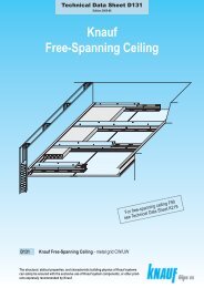
<strong>Knauf</strong> suspended ceilings keep the dead<br />
load of non-load bearing construction components<br />
low and fulfi l the enhanced building<br />
requirements of sound insulation, fi re protection<br />
and thermal insulation. Furthermore,<br />
<strong>Knauf</strong> suspended ceiling systems create<br />
additional space for service or sanitary<br />
installations.<br />
<strong>Knauf</strong> <strong>Seismic</strong> <strong>Design</strong><br />
Suspended Ceilings<br />
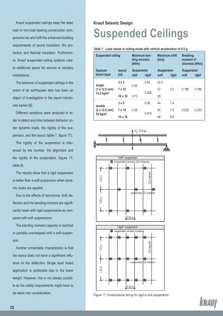
Table 7: Load values in ceiling studs with vertical acceleration of 0.5 g<br />
Suspended ceiling<br />
Gypsum<br />
board layer<br />
layout<br />
[m]<br />
Maximum bending<br />
moment<br />
[kNm]<br />
Maximum shift<br />
[mm]<br />
Breaking<br />
moment of<br />
channels [kNm]<br />
Suspension Suspension Suspension<br />
soft rigid soft rigid soft rigid<br />
The behavior of suspended ceilings in the<br />
event of an earthquake also has been an<br />
object of investigation in the report mentioned<br />
earlier [6].<br />
Different variations were analyzed in order<br />
to detect any links between behavior under<br />
dynamic loads, the rigidity of the suspension,<br />
and the layout (table 7, fi gure 17).<br />
The rigidity of the suspension is infl u-<br />
enced by the number, the alignment and<br />
single<br />
(1 x 12.5 mm)<br />
12.5 kg/m²<br />
double<br />
(2 x 12.5 mm)<br />
25 kg/m²<br />
3 x 5<br />
0.02 22.3<br />
0.20<br />
7 x 15<br />
27<br />
0.005<br />
10 x 10 0.15 25<br />
3 x 5<br />
0.05 44 7.4<br />
7 x 15 0.35<br />
50 7.5<br />
0.015<br />
10 x 10 48 8.0<br />
V' (0.5 g) z<br />
3.0 0.186 0.186<br />
0.222 0.222<br />
the rigidity of the suspenders. (fi gure 17,<br />
table 8).<br />
The results show that a rigid suspension<br />
is better than a soft suspension when dynamic<br />
loads are applied.<br />
Due to the effects of resonance, both defl<br />
ection and the bending moment are signifi -<br />
cantly lower with rigid suspensions as compared<br />
with soft suspensions.<br />
The bending moment capacity is reached<br />
or partially overstepped with a soft suspension.<br />
Another remarkable characteristic is that<br />
the layout does not have a signifi cant infl u-<br />
ence on the defl ection. Single layer board<br />
application is preferable due to the lower<br />
weight. However, this is not always possib-<br />
1.25 m<br />
1.25 m<br />
1.25 m 1.25 m<br />
"soft" suspension<br />
suspenders at every 2nd crossing<br />
0.50 m<br />
"rigid" suspension<br />
suspenders at each crossing<br />
CD channel<br />
suspended CD channel<br />
CD channel<br />
suspended CD channel<br />
le as fi re safety requirements might have to<br />
be taken into consideration.<br />
0.50 m<br />
Figure 17: Constructional set-up for rigid or soft suspensions<br />
12