Knauf Seismic Design
Knauf Seismic Design
Knauf Seismic Design

You also want an ePaper? Increase the reach of your titles
YUMPU automatically turns print PDFs into web optimized ePapers that Google loves.
Table 10: Collapse loads for metal stud shear walls from [9]<br />
Cladding 1 Cladding 2 Spacing of<br />
screws s r<br />
[mm] at<br />
perimeter<br />
Horizontal<br />
load F H<br />
at<br />
collapse<br />
[kN]<br />
Vertical<br />
load F V<br />
at<br />
collapse<br />
[kN]<br />
Number<br />
of tests<br />
Continuation from page 14<br />
...by varying the spacing of the screw<br />
attachment were tested for this research<br />
paper. A dimensioning calculation has been<br />
Gypsum<br />
fi ber board<br />
(e.g. <strong>Knauf</strong><br />
Vidiwall)<br />
Cementous<br />
fi ber board<br />
(e.g. <strong>Knauf</strong><br />
Aquapanel)<br />
Gypsum<br />
fi ber<br />
board<br />
(e.g. <strong>Knauf</strong><br />
Vidiwall)<br />
100 39.8 0 3<br />
150 33.1 0 3<br />
150 43.6 0 3<br />
Chipboard 150 39.9 0 3<br />
Trapezoid<br />
metal sheet<br />
172/150 39.0 0 3<br />
none 200 12.2 30 1<br />
also developed by Bernd Naujoks.<br />
The test results shown in table 10 are not<br />
dimensioning values ; these are breaking<br />
loads with defi ned collapse criteria without<br />
statistical consideration or safety factors.<br />
The collapse of wooden panel partitions is<br />
usually caused by the connections between<br />
the board and the wooden framing members.<br />
For metal stud partitions, however, the col-<br />
1<br />
3<br />
1<br />
3<br />
1<br />
3<br />
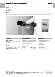
F V<br />
F V<br />
F V<br />
F H<br />
lapse can be caused by the buckling of the<br />
lower end of the pressure-impacted stud if<br />
the spacing of screws is small enough. [11]<br />
Additional reinforcements in this area, e.g.<br />
corner bracing components increase the<br />
load capacity of metal stud shear walls.<br />
260 cm<br />
It should, however, be borne in mind that<br />
the fi gures stated do not take into account<br />
Figure 22: Load set-up for Table 10<br />
125 cm<br />
any effects of creeping under permanent<br />
loads. Hence, it should be ensured that no<br />
permanent loads occur through plastic deformations<br />
or the restraint of fl anking components.<br />
Drywall shear walls can be used up to 5<br />
stories.<br />
Table 11: Comparison of shear capacity of masonry walls and<br />
<strong>Knauf</strong> shear walls<br />
Wall type<br />
(l=5m, h=3m)<br />
Total capacity<br />
kN<br />
Capacity<br />
kN/m<br />
Weight of wall<br />
kg/m²<br />
120 mm masonry 1) 9 1.8 194<br />
180 mm masonry 1) 15 3.0 299<br />
240 mm masonry 1) 20 4.0 405<br />
≥ 75 mm <strong>Knauf</strong> W 111 2) 12 2.4 25<br />
≥ 100 mm <strong>Knauf</strong> W 112 2) 19 3.8 50<br />
1)<br />
Strength of bricks = 15.0 N/mm²<br />
2)<br />
Studs c/c 600 mm. Screw spacing around perimeter 200 mm in both layers.<br />
In table 11 the shear load capacity of masonry<br />
and <strong>Knauf</strong> shear walls is stated for<br />
walls 3 m high and 5 m long.<br />
It shows that the shear capacity of <strong>Knauf</strong><br />
partitions is comparable to the capacity of<br />
conventional masonry with a signifi cantly<br />
lower weight.<br />
Material values for dimensioning are stated<br />
in tables 12 and 13, pg 17.<br />
15