Modular Housings VariTrans® B 13000
Modular Housings VariTrans® B 13000
Modular Housings VariTrans® B 13000

Create successful ePaper yourself
Turn your PDF publications into a flip-book with our unique Google optimized e-Paper software.
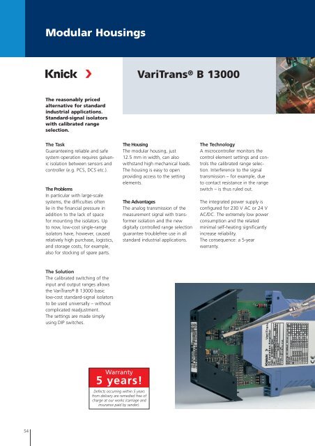
<strong>Modular</strong> <strong>Housings</strong><br />
VariTrans ® B <strong>13000</strong><br />
The reasonably priced<br />
alternative for standard<br />
industrial applications.<br />
Standard-signal isolators<br />
with calibrated range<br />
selection.<br />
The Task<br />
Guaranteeing reliable and safe<br />
system operation requires galvanic<br />
isolation between sensors and<br />
controller (e.g. PCS, DCS etc.).<br />
The Problems<br />
In particular with large-scale<br />
systems, the difficulties often<br />
lie in the financial pressure in<br />
addition to the lack of space<br />
for mounting the isolators. Up<br />
to now, low-cost single-range<br />
isolators have, however, caused<br />
relatively high purchase, logistics,<br />
and storage costs, for example,<br />
also for stocking of spare parts.<br />
The Housing<br />
The modular housing, just<br />
12.5 mm in width, can also<br />
withstand high mechanical loads.<br />
The housing is easy to open<br />
providing access to the setting<br />
elements.<br />
The Advantages<br />
The analog transmission of the<br />
measurement signal with transformer<br />
isolation and the new<br />
digitally controlled range selection<br />
guarantee troublefree use in all<br />
standard industrial applications.<br />
The Technology<br />
A microcontroller monitors the<br />
control element settings and controls<br />
the calibrated range selection.<br />
Interference to the signal<br />
transmission – for example, due<br />
to contact resistance in the range<br />
switch – is thus ruled out.<br />
The integrated power supply is<br />
configured for 230 V AC or 24 V<br />
AC/DC. The extremely low power<br />
consumption and the related<br />
minimal self-heating significantly<br />
increase reliability.<br />
The consequence: a 5-year<br />
warranty.<br />
The Solution<br />
The calibrated switching of the<br />
input and output ranges allows<br />
the VariTrans® B <strong>13000</strong> basic<br />
low-cost standard-signal isolators<br />
to be used universally – without<br />
complicated readjustment.<br />
The settings are made simply<br />
using DIP switches.<br />
Warranty<br />
5 years!<br />
Defects occurring within 5 years<br />
from delivery are remedied free of<br />
charge at our works (carriage and<br />
insurance paid by sender).<br />
54
Isolation Amplifiers<br />
for Standard Signals<br />
Isolation Amplifiers<br />
Transmitters<br />
Indicators<br />
Process Analytics<br />
Portable Meters<br />
Laboratory Meters<br />
Sensors<br />
Fittings<br />
■ The Facts<br />
Flexible and accurate<br />
Calibrated range selection without<br />
complicated readjustment<br />
Low-cost<br />
The competitively priced solution<br />
for standand applications; considerable<br />
reduction in purchasing,<br />
logistics, and storage costs, for<br />
example for stocking of spare<br />
parts.<br />
Extremely compact design<br />
12.5 mm modular housing;<br />
up to 80 active isolators per<br />
meter of mounting rail<br />
Maximum reliability<br />
No repair and failure costs<br />
5-year warranty<br />
<strong>Modular</strong> <strong>Housings</strong><br />
Fast and easy configuration<br />
Housing simple to open<br />
3-port isolation<br />
Protection against incorrect<br />
measurements or damage<br />
55
<strong>Modular</strong> <strong>Housings</strong><br />
VariTrans ® B <strong>13000</strong><br />
■ Product Line<br />
Devices Input Output Order No.<br />
l–––––––––––––––––––––––––– l––––––––––––––––––––––––––––––––––––––––––––––––––––––––––––––––––––––––––––––––– –<br />
VariTrans® B <strong>13000</strong> 0 ... 20 mA, 0 ... 20 mA, B <strong>13000</strong> F1<br />
Input and output 4 ... 20 mA, 4 ... 20 mA,<br />
calibrated switchable 0 ... 10 V 0 ... 10 V<br />
l–––––––––––––––––––––––––– l––––––––––––––––––––––––––––––––––––––––––––––––––––––––––––––––––––––––––––––––– –<br />
VariTrans® B <strong>13000</strong> 0 ... 20 mA 0 ... 20 mA B 13016 F1<br />
with fixed settings 0 ... 20 mA 4 ... 20 mA B 13017 F1<br />
0 ... 20 mA 0 ... 10 V B 13018 F1<br />
4 ... 20 mA 0 ... 20 mA B 13026 F1<br />
4 ... 20 mA 4 ... 20 mA B 13016 F1<br />
4 ... 20 mA 0 ... 10 V B 13028 F1<br />
0 ... 10 V 0 ... 20 mA B 13036 F1<br />
0 ... 10 V 4 ... 20 mA B 13037 F1<br />
0 ... 10 V 0 ... 10 V B 13038 F1<br />
Power supply<br />
l––––––––––––––––––––––––––––––––––––––––––––––––––––––––––––––––––––––––––––––––––––––––––––––––––––––––––––––––<br />
230 V AC<br />
l––––––––––––––––––––––––––––––––––––––––––––––––––––––––––––––––––––––––––––––––––––––––––––––––––––––––––––––––<br />
24 V AC/DC 336<br />
■ Specifications<br />
Input data<br />
l–––––––––––––––––––––––––– l–––––––––––––––––––––––––––––––––––––––––––––––––––––––––––––––––––––––––––––––––––<br />
Inputs 0 ... 20 mA Terminal selectable/switchable (factory setting 0 ... 20 mA)<br />
4 ... 20 mA or fixed settings (see Product line)<br />
0 ... 10 V<br />
l–––––––––––––––––––––––––– l–––––––––––––––––––––––––––––––––––––––––––––––––––––––––––––––––––––––––––––––––––<br />
Input resistance Current input Voltage drop approx. 500 mV at 20 mA<br />
Voltage input<br />
Approx. 1 Mohm<br />
l–––––––––––––––––––––––––– l–––––––––––––––––––––––––––––––––––––––––––––––––––––––––––––––––––––––––––––––––––<br />
Overload Current input ≤ 300 mA<br />
Voltage input Voltage limitation with suppressor diode 30 V,<br />
max. permitted continuous current 30 mA<br />
Output data<br />
l–––––––––––––––––––––––––– l–––––––––––––––––––––––––––––––––––––––––––––––––––––––––––––––––––––––––––––––––––<br />
Outputs 0 ... 20 mA Switchable (factory setting 0 ... 20 mA)<br />
4 ... 20 mA or fixed settings (see Product line)<br />
0 ... 10 V<br />
(Transmission of negative measurement signals up to approx. –5 % full scale)<br />
56
Isolation Amplifiers<br />
for Standard Signals<br />
Isolation Amplifiers<br />
Transmitters<br />
Indicators<br />
Process Analytics<br />
Portable Meters<br />
Laboratory Meters<br />
Sensors<br />
Fittings<br />
Specifications (continued)<br />
Output data (continued)<br />
l–––––––––––––––––––––––––– l–––––––––––––––––––––––––––––––––––––––––––––––––––––––––––––––––––––––––––––––––––<br />
Load With output current ≤ 10 V (500 ohms at 20 mA)<br />
With output voltage ≤ 10 mA (1 kohm at 10 V) 1)<br />
l–––––––––––––––––––––––––– l–––––––––––––––––––––––––––––––––––––––––––––––––––––––––––––––––––––––––––––––––––<br />
Offset<br />
20 µA or 10 mV<br />
l–––––––––––––––––––––––––– l–––––––––––––––––––––––––––––––––––––––––––––––––––––––––––––––––––––––––––––––––––<br />
Residual ripple<br />
< 20 mVrms<br />
Transmission behavior<br />
l––––––––––––––––––––––––––<br />
Gain error<br />
l––––––––––––––––––––––––––<br />
Cut-off frequency<br />
l––––––––––––––––––––––––––<br />
Temperature coefficient 2)<br />
l–––––––––––––––––––––––––––––––––––––––––––––––––––––––––––––––––––––––––––––––––––<br />
< 0.4 % meas.val. (DC)<br />
l–––––––––––––––––––––––––––––––––––––––––––––––––––––––––––––––––––––––––––––––––––<br />
> 1 kHz, –3 dB<br />
l–––––––––––––––––––––––––––––––––––––––––––––––––––––––––––––––––––––––––––––––––––<br />
0.015 %/K full scale (reference temperature 23 °C)<br />
<strong>Modular</strong> <strong>Housings</strong><br />
Power supply<br />
l–––––––––––––––––––––––––– l–––––––––––––––––––––––––––––––––––––––––––––––––––––––––––––––––––––––––––––––––––<br />
Power supply<br />
230 V AC, –15 % +10 %, 48 ... 62 Hz, approx. 2 VA<br />
l–––––––––––––––––––––––––– l–––––––––––––––––––––––––––––––––––––––––––––––––––––––––––––––––––––––––––––––––––<br />
Option 336: 24 V AC/DC AC: ±15 %, 48 ... 62 Hz, approx. 2 VA<br />
DC: ±15%, approx. 0.9 W<br />
Isolation<br />
l–––––––––––––––––––––––––– l–––––––––––––––––––––––––––––––––––––––––––––––––––––––––––––––––––––––––––––––––––<br />
Galvanic isolation<br />
3-port isolation between input, output and power supply<br />
l–––––––––––––––––––––––––– l–––––––––––––––––––––––––––––––––––––––––––––––––––––––––––––––––––––––––––––––––––<br />
Test voltage<br />
3.25 kV AC input against output against power supply<br />
l–––––––––––––––––––––––––– l–––––––––––––––––––––––––––––––––––––––––––––––––––––––––––––––––––––––––––––––––––<br />
Working voltage<br />
600 V AC/DC with overvoltage category II and pollution degree 2 according to<br />
(basic insulation) EN 61010-1.<br />
For applications with high working voltages, you should ensure there is sufficient<br />
spacing or isolation from neighboring devices and protection against electric shocks.<br />
Standards and approvals<br />
l–––––––––––––––––––––––––– l–––––––––––––––––––––––––––––––––––––––––––––––––––––––––––––––––––––––––––––––––––<br />
Surge withstand 5 kV, 1.2/50 µs, according to IEC 255-4<br />
l–––––––––––––––––––––––––– l–––––––––––––––––––––––––––––––––––––––––––––––––––––––––––––––––––––––––––––––––––<br />
EMC 3) 89/336/EEC directive; EN 61326<br />
l–––––––––––––––––––––––––– l–––––––––––––––––––––––––––––––––––––––––––––––––––––––––––––––––––––––––––––––––––<br />
Approvals CUL: File No. E 216767, Standards UL 3101-1, CSA-C22.2-95, No. 10101-1<br />
GL: No. 14627-99 HH<br />
1) Higher voltage output load on request<br />
2) Average TC in specified operating temperature range –10 ºC ... +60 ºC<br />
3) Slight deviations are possible while there is interference<br />
57
<strong>Modular</strong> <strong>Housings</strong><br />
VariTrans ® B <strong>13000</strong><br />
Specifications (continued)<br />
Other data<br />
l–––––––––––––––––––––––––– l–––––––––––––––––––––––––––––––––––––––––––––––––––––––––––––––––––––––––––––––––––<br />
MTBF 4)<br />
Approx. 91 years<br />
l–––––––––––––––––––––––––– l–––––––––––––––––––––––––––––––––––––––––––––––––––––––––––––––––––––––––––––––––––<br />
Ambient temperature Operation: –10 ... +60 ºC<br />
Transport and storage: –20 ... +85 ºC<br />
l–––––––––––––––––––––––––– l–––––––––––––––––––––––––––––––––––––––––––––––––––––––––––––––––––––––––––––––––––<br />
Design<br />
<strong>Modular</strong> housing type F1, with screw terminals, width 12.5 mm,<br />
see dimension drawings for further measurements<br />
l–––––––––––––––––––––––––– l–––––––––––––––––––––––––––––––––––––––––––––––––––––––––––––––––––––––––––––––––––<br />
Ingress protection IP 20<br />
l–––––––––––––––––––––––––– l–––––––––––––––––––––––––––––––––––––––––––––––––––––––––––––––––––––––––––––––––––<br />
Mounting For 35 mm top hat rail to EN 50022<br />
See dimension drawings for conductor cross section<br />
l–––––––––––––––––––––––––– l–––––––––––––––––––––––––––––––––––––––––––––––––––––––––––––––––––––––––––––––––––<br />
Weight<br />
Approx. 150 g<br />
4) Mean Time Between Failures – MTBF – according to EN 61709 (SN 29500). Conditions: stationary operation in well-kept rooms, average ambient temperature<br />
40 ºC, no ventilation, continuous operation<br />
■ Block Diagram<br />
+<br />
Voltage<br />
input<br />
–<br />
–<br />
Current<br />
input<br />
+<br />
C 1 nF<br />
Z 30 V<br />
C 1 nF<br />
C 1 nF<br />
Z 18 V<br />
+<br />
Output<br />
–<br />
Power supply 230 V AC, optional 24 V AC/DC<br />
58
Isolation Amplifiers<br />
for Standard Signals<br />
Isolation Amplifiers<br />
Transmitters<br />
Indicators<br />
Process Analytics<br />
Portable Meters<br />
Laboratory Meters<br />
Sensors<br />
Fittings<br />
■ Application Examples<br />
Electrical isolation<br />
for safe coupling of the measurement signals to the evaluation electronics<br />
Transmitter<br />
e.g. °C,<br />
bar<br />
0/4 ... 20 mA<br />
0 ... 10 V<br />
VariTrans® B <strong>13000</strong><br />
Power supply<br />
e.g. DCS, PCS<br />
<strong>Modular</strong> <strong>Housings</strong><br />
Signal conversion<br />
e.g. conversion of voltage signals into current signals for interference-free<br />
signal transmission over long distances<br />
Voltage output<br />
VariTrans® B <strong>13000</strong><br />
0 ... 10 V<br />
4 ... 20 mA<br />
e.g.<br />
indicator,<br />
DCS, PCS<br />
Power supply<br />
Load increase<br />
e. g. for low load capability signals<br />
Current output<br />
e.g. °C,<br />
bar<br />
0 ... 20 mA<br />
max. load<br />
50 Ø, e.g. DCS<br />
VariTrans® B <strong>13000</strong><br />
R I = 12.5 Ø<br />
0 ... 20 mA<br />
max. load 600 Ø<br />
Power supply<br />
59
<strong>Modular</strong> <strong>Housings</strong><br />
VariTrans ® B <strong>13000</strong><br />
Application Examples (continued)<br />
Signal Multiplication<br />
e. g. for correct evaluation of measurement signals in different devices<br />
Current output<br />
VariTrans® B <strong>13000</strong><br />
Voltage output<br />
VariTrans® B <strong>13000</strong><br />
0/4 ... 20 mA<br />
e.g. DCS, PCS,<br />
displays<br />
0 ... 10 V<br />
e.g. DCS, PCS,<br />
displays<br />
Power supply<br />
Power supply<br />
e.g. DCS, PCS,<br />
displays<br />
e.g. DCS, PCS,<br />
displays<br />
Power supply<br />
Power supply<br />
2-wire application<br />
for simple set-up of 2-wire measuring circuits<br />
2-wire<br />
transmitter<br />
e.g. °C,<br />
bar<br />
4 ... 20 mA<br />
VariTrans® B <strong>13000</strong><br />
0/4 ... 20 mA<br />
or 0 ... 10 V<br />
Power supply<br />
24 V DC<br />
Mains<br />
adapter<br />
Power supply<br />
60
Isolation Amplifiers<br />
for Standard Signals<br />
Isolation Amplifiers<br />
Transmitters<br />
Indicators<br />
Process Analytics<br />
Portable Meters<br />
Laboratory Meters<br />
Sensors<br />
Fittings<br />
■ Dimension Drawings and Terminal Assignments<br />
12.5<br />
111<br />
7 8<br />
5 6<br />
Fixed<br />
screw<br />
terminals<br />
99<br />
<strong>Modular</strong> <strong>Housings</strong><br />
1 2<br />
3 4<br />
Metal lock for fastening on the DIN rail<br />
Terminal Assignments<br />
1 Input + Current<br />
2 Input – Current<br />
3 Input + Voltage<br />
4 Input – Voltage<br />
Conductor cross-section max. 2.5 mm 2<br />
5 Output +<br />
6 Output –<br />
7 Power supply ~ –<br />
8 Power supply ~ –<br />
Multi-wire connection max. 1 mm 2 (two wires with same cross-section)<br />
All dimensions in mm!<br />
61