DLP-RFID - FTDI
DLP-RFID - FTDI
DLP-RFID - FTDI

You also want an ePaper? Increase the reach of your titles
YUMPU automatically turns print PDFs into web optimized ePapers that Google loves.
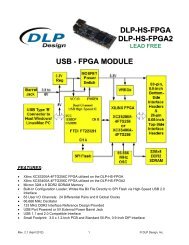
<strong>DLP</strong>-<strong>RFID</strong>1<br />
*LEAD-FREE*<br />
OEM Version<br />
FEATURES:<br />
• ISO 15693, 18000-3, Tag-it HF-I Compatible<br />
• Read UID/SID of Up to 15 Tags Simultaneously<br />
• 13.56MHz Reader/Writer<br />
• Built-in Antenna: Up to 4-Inch Read Range<br />
• FCC/IC/CE Modular Approval in Place<br />
• Permanent Unique Serial Number Accessible Via USB<br />
• Integrated Pass/Fail Beeper<br />
• USB Port Powered from Host PC (USB 1.1/2.0 Compatible)<br />
• USB Drivers Provided for Windows XP, XPx64, Server2003, 2000, 98, ME<br />
• Software Development Library Support for Visual<br />
C++/Visual Basic<br />
APPLICATIONS:<br />
• Real-Time Security<br />
• Personal Identification<br />
• Pharmaceutical Tracking<br />
• Inventory/Asset Management & Tracking<br />
• Library/Book Management & Tracking<br />
• Baggage Tagging<br />
• Sports Event Timing<br />
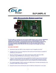
1.0 INTRODUCTION Retail Version: Includes reader, retractable<br />
USB cable and five peel & stick <strong>RFID</strong> tags<br />
The <strong>DLP</strong>-<strong>RFID</strong>1 is a low-cost, USB-powered module for reading from and writing to ISO 15693, ISO<br />
18000-3, and Tag-it intelligent <strong>RFID</strong> transponder tags. It has the ability to both read and write up to<br />
256 bytes of data in addition to reading the unique identifier (UID/SID). All of the <strong>DLP</strong>-<strong>RFID</strong>1’s<br />
electronics and antenna reside within the compact unit, and all operational power is taken from the host<br />
PC via the USB interface. The range of the internal antenna is up to 4 inches depending upon the size of<br />
the tag being read.<br />
Rev 1.2 (May 2007) 1 © <strong>DLP</strong> Design, Inc.
2.0 <strong>RFID</strong> BASICS<br />
<strong>RFID</strong> stands for Radio Frequency IDentification. It is an electronic technology whereby digital data<br />
encoded in an <strong>RFID</strong> Tag (or transponder) is retrieved utilizing a reader. In contrast to bar code<br />
technology, <strong>RFID</strong> systems do not require line-of-sight access to the tag in order to retrieve the tag’s data,<br />
and they are well suited to harsh environments.<br />
An <strong>RFID</strong> tag consists of an integrated circuit attached to an antenna. In the case of the tags used with<br />
the <strong>DLP</strong>-<strong>RFID</strong>1, the antenna is in the form of conductive ink “printed” on a material that allows for<br />
connection to the integrated circuit. This type of passive (battery-free) tag is commonly referred to as an<br />
“inlay”.<br />
The <strong>RFID</strong> reader (or “interrogator”) is typically a microcontroller-based radio transceiver that powers the<br />
tag with a time-varying electromagnetic radio frequency (RF) field. When the RF field passes through the<br />
tag’s antenna, AC voltage is generated in the antenna and rectified to supply power to the tag. Once<br />
powered, the tag can receive commands from the reader. The information stored in the tag can then be<br />
read by the reader and sent back to the host PC for processing.<br />
The data in the tag consists of a hard-coded, permanent serial number (or UID) and user memory that<br />
can be written to, read from and locked if desired. Once locked, user data can still be read but not<br />
changed.<br />
3.0 SPECIFICATIONS<br />
Reader Frequency<br />
Output Power<br />
Range (Integral Antenna)<br />
Tags/Protocols Supported<br />
Communications Interface<br />
Operational Power – Active<br />
Operational Power – Idle<br />
Antenna<br />
USB Driver Support<br />
Physical Dimensions – OEM<br />
Physical Dimensions – Retail<br />
Operating Temperature<br />
13.56MHz<br />
200mW MAX<br />
4 Inches MAX<br />
Tag-It*, ISO18000-3, ISO15693<br />
USB 1.1/2.0 Compatible, Mini-B 5-Pin Connector<br />
120mA<br />
15mA<br />
On-Board Antenna, SMA Position Available**<br />
Windows XP, XPx64, Server2003, 2000, 98, ME<br />
PCB: .20x2.17x3.12” typ. (5.1x55.1x79.3mm)<br />
Enclosure: .83x2.3x3.25” typ. (21.1x58.4x82.6mm)<br />
0-70°C<br />
* Limited Support – See Supported Tag Library Functions for details.<br />
** See Integral Antenna Section for important regulatory details.<br />
4.0 PERMANENT READER SERIAL NUMBER<br />
Each <strong>DLP</strong>-<strong>RFID</strong>1 contains a unique, 32-bit, hard-coded serial number that cannot be altered by any<br />
means. The serial number can be read via the USB interface and used to identify the reader via the host<br />
software.<br />
Rev 1.2 (May 2007) 2 © <strong>DLP</strong> Design, Inc.
5.0 APPLICATION DEVELOPMENT<br />
A software library is available for free download upon purchase of the <strong>DLP</strong>-<strong>RFID</strong>1 that allows reading the<br />
serial number (UID/SID) of a single transponder tag, access to the reader’s permanent serial number and<br />
control of the integrated pass/fail beeper. The library is designed to work with any Windows programming<br />
language that supports COM objects. Demonstration software is also included that shows how to use the<br />
library in Visual C++ and Visual Basic programming languages.<br />
A Professional Developer’s Library is also available as a separate purchase that allows for the reading of<br />
multiple tags, writing to and reading from the available user memory and other available features of the<br />
tags and <strong>DLP</strong>-<strong>RFID</strong>1 reader.<br />
6.0 SUPPORTED TAG LIBRARY FUNCTIONS<br />
The free version of the software library for the <strong>DLP</strong>-<strong>RFID</strong>1 only supports the reading of a single tag’s<br />
serial number, access to the reader’s permanent serial number, and control of the integrated pass/fail<br />
beeper. The Professional Developer’s Library supports these additional functions:<br />
Texas Instruments Tag-It Transponder Tags:<br />
Single/Multiple SID Read (Inventory)<br />
Texas Instruments HF-I Plus Transponder Tags:<br />
Single/Multiple UID Read (Inventory)<br />
Read Single Block (Addressed and Non-Addressed)<br />
Write Single Block (Addressed and Non-Addressed)<br />
Lock Block (Addressed and Non-Addressed)<br />
Read/Write AFI (Addressed and Non-Addressed)<br />
Lock AFI (Addressed and Non-Addressed)<br />
Read Multiple Block Lock State (Addressed and Non-Addressed)<br />
Read Multiple Blocks (8 Per Read; Addressed and Non-Addressed)<br />
Read/Write DSFID (Addressed and Non-Addressed)<br />
Lock DSFID (Addressed and Non-Addressed)<br />
Texas Instruments HF-I Pro Transponder Tags:<br />
Single/Multiple UID Read (Inventory)<br />
Read Single Block (Addressed and Non-Addressed)<br />
Write Single Block (Addressed and Non-Addressed)<br />
Lock Block (Addressed and Non-Addressed)<br />
Read/Write AFI (Addressed and Non-Addressed)<br />
Lock AFI (Addressed and Non-Addressed)<br />
Read Single Block Lock State (Addressed and Non-Addressed)<br />
Write/Lock Password (Addressed Command)<br />
Write Block With Password (Addressed Command; Password Required)<br />
Kill Tag (Addressed Command; Password Required)<br />
Additionally, a low-power Mode Enable command is provided to reduce current consumption to<br />
approximately 15mA when communication with a tag is not required.<br />
Rev 1.2 (May 2007) 3 © <strong>DLP</strong> Design, Inc.
7.0 TAG MEMORY MAP<br />
The user memory in the transponder tags is arranged in “blocks” or groups of 4 bytes each. Each block<br />
can be written (until locked) and read. The Pro tags have 8 blocks, and the Plus tags have 64 blocks.<br />
Additional details are available in the Professional Developer’s Library (purchased separately).<br />
Pro Tags (256 Bits)<br />
Addr<br />
0x00<br />
0x01<br />
0x02<br />
0x06<br />
0x07<br />
32 bits<br />
User<br />
Lock<br />
Bit<br />
}<br />
User<br />
Data<br />
Plus Tags (2048 Bits)<br />
Addr<br />
0x00<br />
0x01<br />
0x02<br />
0x3E<br />
0x3F<br />
32 bits<br />
User<br />
Lock<br />
Bit<br />
}<br />
User<br />
Data<br />
0x0B<br />
AFI<br />
Password<br />
DSFID<br />
AFI<br />
8.0 SUPPORTED TRANSPONDER TAGS<br />
The <strong>DLP</strong>-<strong>RFID</strong>1 was designed to support transponder tags manufactured by Texas Instruments. The<br />
following Texas Instruments tags have been tested and approved for use with the <strong>DLP</strong>-<strong>RFID</strong>1:<br />
Laundry Tags:<br />
Pro: RX-HDT-DVBS-N0<br />
Plus: RF-HDT-DVBB<br />
24mm Circular:<br />
Pro: RI-I16-114A-S1<br />
Plus: RI-I16-112A (Peel-N-Stick Version<br />
Sold in 10- Packs under Part Number<br />
<strong>DLP</strong>-<strong>RFID</strong>TAG)<br />
Dimensions In. (mm):<br />
.87 x .12<br />
(22 x 3)<br />
.95 (24)<br />
<strong>DLP</strong>-<strong>RFID</strong>TAG:<br />
1.5 (38)<br />
CD/DVD Circular:<br />
Pro: RI-I17-114A-S1<br />
Plus: RI-I17-112A<br />
1.29 (32.6)<br />
Rev 1.2 (May 2007) 4 © <strong>DLP</strong> Design, Inc.
Mini-Rectangle:<br />
Pro: RI-I03-114A-S1<br />
Plus: RI-I03-112A<br />
1.5 x .89<br />
(38 x 22.6)<br />
Square:<br />
Pro: RI-I11-114A-S1<br />
Plus: RI-I11-112A<br />
1.78 x 1.78<br />
(45.2 x 45.2)<br />
Large Rectangle:<br />
Pro: RI-I02-114A-S1<br />
Plus: RI-I02-112A<br />
3.0 x 1.78<br />
(76.2 x 45.2)<br />
9.0 REGULATORY AGENCY CONSIDERATIONS<br />
9.1 AGENCY IDENTIFICATION NUMBERS<br />
Compliance with the appropriate regulatory agencies is essential in the deployment of all transceiver<br />
devices. <strong>DLP</strong> Design has obtained modular approval for this RF product such that an OEM need only<br />
meet a few basic requirements in order to utilize their end product under this approval. Corresponding<br />
agency identification numbers are listed below:<br />
Part Number US / FCC CANADA / IC<br />
<strong>DLP</strong>-<strong>RFID</strong>1 SX90<strong>RFID</strong>1 5675A-0<strong>RFID</strong>1<br />
Rev 1.2 (May 2007) 5 © <strong>DLP</strong> Design, Inc.
9.2 INTEGRAL ANTENNA<br />
The <strong>DLP</strong>-<strong>RFID</strong>1 is approved for use with the integral antenna only. Modifying the <strong>DLP</strong>-<strong>RFID</strong>1’s PCB<br />
antenna or modifying the PCB to use an external antenna will void all agency compliance approvals.<br />
A location for mounting an SMA connector (purchased separately) is available on the <strong>DLP</strong>-<strong>RFID</strong>1’s<br />
printed circuit board. Mounting the SMA connector requires the removal of the RF shield from the PCB.<br />
Additionally, the on-board antenna must be isolated from the signal path leading to the SMA connector<br />
via the removal of capacitor C37. This output is designed to drive a 13.56MHz, 50-Ohm antenna. The<br />
use of any other type of antenna may cause permanent damage to the <strong>DLP</strong>-<strong>RFID</strong>1.<br />
9.3 FCC/IC REQUIREMENTS FOR MODULAR APPROVAL<br />
Any changes or modifications to the <strong>DLP</strong>-<strong>RFID</strong>1’s printed circuit board could void the user’s authority to<br />
operate the equipment.<br />
9.4 WARNINGS<br />
Operation is subject to the following two conditions: (1) This device may not cause harmful interference,<br />
and (2) this device must accept any interference received, including interference that may cause<br />
undesirable operation.<br />
This device is intended for use under the following conditions:<br />
1. The transmitter module may not be co-located with any other transmitter or antenna; and<br />
2. The module is approved using the FCC’s “unlicensed modular transmitter approval” method.<br />
As long as these two conditions are met, further transmitter testing will not be required. However, the<br />
OEM integrator is still responsible for testing their end product for any additional compliance measures<br />
necessitated by the installation of this module (i.e. digital device emissions, PC peripheral requirements,<br />
etc.).<br />
Note: In the event that these conditions cannot be met (i.e. co-location with another transmitter), then<br />
the FCC authorization is no longer valid, and the corresponding FCC ID may not be used on the final<br />
product. Under these circumstances, the OEM integrator will be responsible for re-evaluating the end<br />
product (including the transmitter) and obtaining a separate FCC authorization.<br />
9.5 OEM PRODUCT LABELING<br />
The final end product must be labeled in a visible area with the following text:<br />
“Contains TX FCC ID: SX90<strong>RFID</strong>1”<br />
9.6 RF EXPOSURE<br />
In order to comply with FCC RF exposure requirements, the antenna used for this transmitter must not<br />
be co-located or operating in conjunction with any other antenna or transmitter.<br />
Rev 1.2 (May 2007) 6 © <strong>DLP</strong> Design, Inc.
9.7 ADDITIONAL INFORMATION FOR OEM INTEGRATORS<br />
The end user should NOT be provided with any instructions on how to remove or install the <strong>DLP</strong>-<strong>RFID</strong>1.<br />
10.0 DISCLAMER<br />
Neither the whole nor any part of the information contained herein nor the product described in this<br />
datasheet may be adapted or reproduced in any material or electronic form without the prior written<br />
consent of the copyright holder.<br />
This product and its documentation are supplied on an as-is basis, and no warranty as to their suitability<br />
for any particular purpose is either made or implied. <strong>DLP</strong> Design will not accept any claim for damages<br />
whatsoever arising as a result of use or failure of this product. Your statutory rights are not affected.<br />
This product or any variant of it is not intended for use in any medical appliance, device, or system in<br />
which the failure of the product might reasonably be expected to result in personal injury.<br />
This document provides preliminary information that may be subject to change without notice.<br />
11.0 CONTACT INFORMATION<br />
<strong>DLP</strong> Design, Inc.<br />
1605 Roma Lane<br />
Allen, TX 75013<br />
Phone: 469-964-8027<br />
Fax: 415-901-4859<br />
Email: support@dlpdesign.com<br />
Internet: http://www.dlpdesign.com<br />
Rev 1.2 (May 2007) 7 © <strong>DLP</strong> Design, Inc.