Model 464 Electronic Control Unit User Guide - Ekotechnika
Model 464 Electronic Control Unit User Guide - Ekotechnika
Model 464 Electronic Control Unit User Guide - Ekotechnika

You also want an ePaper? Increase the reach of your titles
YUMPU automatically turns print PDFs into web optimized ePapers that Google loves.
September 8, 2010<br />
#109652<br />
<strong>Model</strong> <strong>464</strong><br />
<strong>Electronic</strong> <strong>Control</strong> <strong>Unit</strong> <strong>User</strong> <strong>Guide</strong>
<strong>Model</strong> <strong>464</strong> <strong>Electronic</strong> <strong>Control</strong> <strong>Unit</strong> <strong>User</strong> <strong>Guide</strong> - Contents<br />
1.0 Introduction 1<br />
1.1 Operating Principles 1<br />
1.2 <strong>Model</strong> <strong>464</strong> <strong>Electronic</strong> <strong>Control</strong> <strong>Unit</strong> Specifications 1<br />
1.3 <strong>Control</strong> Panel 2<br />
1.4 LCD Display 2<br />
2.0 <strong>Control</strong> <strong>Unit</strong> Operation 3<br />
2.1 Start Up 3<br />
2.1.1 Main Menu 3<br />
2.2 LCD Contrast 4<br />
2.3 About 4<br />
2.4 Preset Flow Rates 4<br />
2.5 <strong>User</strong> Flow Rates 5<br />
2.5.1 Saved Settings 5<br />
Edit Settings 6<br />
Delete Settings 6<br />
2.5.2 Create Setting 7<br />
2.6 Automatic Drive/Vent Cycles 7<br />
2.7 Manual Drive/Vent Cycles 8<br />
2.8 Battery Replacement 8<br />
3.0 Pumping Instructions 9<br />
3.1 Preparation 9<br />
3.2 Pumping Set Up 9<br />
3.3 Pump Optimization 10<br />
Bladder Pumps 10<br />
Double Valve Pumps 10
<strong>Model</strong> <strong>464</strong> <strong>Electronic</strong> <strong>Control</strong> <strong>Unit</strong> <strong>User</strong> <strong>Guide</strong><br />
1.0 Introduction<br />
1.1 Operating Principles<br />
The <strong>Model</strong> <strong>464</strong> <strong>Electronic</strong> <strong>Control</strong> <strong>Unit</strong> controls the supply of compressed gas to<br />
pneumatic pumps. Drive (pressure) and vent periods are cycled to provide water<br />
flow. During pressurization periods, water is forced into the sample tubing. The<br />
vent period allows water to re-enter (recharge) the pump. Cycle repetition may<br />
be controlled manually or automatically using pre-set pumping rates.<br />
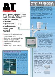
Manual <strong>Control</strong> Button<br />
Air Out<br />
Air In<br />
Battery Enclosure<br />
Regulator<br />
Pressure Gauge<br />
Figure 1-1 <strong>Model</strong> <strong>464</strong> <strong>Electronic</strong> <strong>Control</strong> <strong>Unit</strong><br />
1.2 <strong>Model</strong> <strong>464</strong> <strong>Electronic</strong> <strong>Control</strong> <strong>Unit</strong> Specifications<br />
<strong>Model</strong> <strong>464</strong> Specifications<br />
Operating Temperature: -20ºC to 50ºC<br />
Weight:<br />
Dimensions:<br />
Drive/Vent Time Range:<br />
Maximum Site Name Length:<br />
Memory Capacity:<br />
Battery Life:<br />
Maximum Output Pressure:<br />
Maximum Input Pressure:<br />
5 lbs (2.3 Kg)<br />
9.1" x 10.2" x 4.9” (23 cm x 26 cm x 12 cm)<br />
1-999 seconds<br />
16 characters (upper or lowercase and numeric)<br />
99 user flow rates in non-volatile FRAM, 3 preset in Flash<br />
40,000 drive/vent cycles @ 25ºC from 4 AA alkaline batteries<br />
(100 hours based on 10 second drive/vent cycles)<br />
125 psi (861 KPa)<br />
150 psi (1034 KPa)<br />
Page 1
<strong>Model</strong> <strong>464</strong> <strong>Electronic</strong> <strong>Control</strong> <strong>Unit</strong> <strong>User</strong> <strong>Guide</strong><br />
Note:<br />
Pressing any<br />
key will turn the<br />
<strong>Control</strong> <strong>Unit</strong><br />
on (except Manual <strong>Control</strong><br />
button).<br />
1.3 <strong>Control</strong> Panel<br />
OK<br />
OK button: selects a highlighted menu item (also toggles between lower<br />
and uppercase letters and pressure units). Press and hold for at least 3 seconds<br />
to turn the <strong>Control</strong> <strong>Unit</strong> off. (However, this will not work in the Contrast Menu,<br />
you can only use the left cursor key to exit the menu, and the plus/minus keys<br />
to adjust the contrast.)<br />
Cursor keys: navigate through the menus and menu items.<br />
Note:<br />
The <strong>Control</strong><br />
<strong>Unit</strong> will turn off<br />
automatically<br />
after 5 minutes of being idle,<br />
provided that cycling is not<br />
active.<br />
Plus/Minus keys: cycle through numbers and letters when editing or<br />
creating new flow rates. Increase/decrease LCD display contrast. (Hold down<br />
to scroll quickly through values).<br />
Manual <strong>Control</strong> Valve: allows manual operation of the <strong>Control</strong> <strong>Unit</strong>. When<br />
pushed the solenoid opens. See Page 8.<br />
Air In: connection for the supply line from the compressed gas supply source.<br />
(In-line filter is not required.)<br />
Air Out: connection for the drive line from the pump.<br />
Regulator: sets the pumping pressure. Turn clockwise to increase the pumping<br />
pressure and counter-clockwise to decrease pressure.<br />
Pressure Gauge: displays the pumping pressure.<br />
Battery Enclosure: houses four (4) AA alkaline batteries.<br />
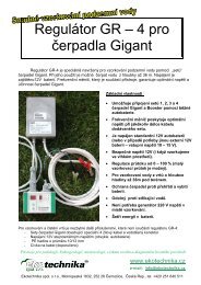
1.4 LCD Display<br />
99<br />
ECU <strong>464</strong> Main Menu<br />
Preset Flow Rates<br />
<strong>User</strong> Flow Rates<br />
LCD Contrast<br />
About<br />
Note:<br />
Figure 1-2 <strong>Electronic</strong> <strong>Control</strong> <strong>Unit</strong> LCD Display<br />
Battery Life is<br />
40,000 drive/<br />
Bar icons : indicate 99 the amount of time remaining before the <strong>Control</strong> <strong>Unit</strong><br />
vent cycles or<br />
automatically ECU <strong>464</strong> Main turns Menu off. Each of the four bars represents 1 minute 15 seconds.<br />
100 hours at 10 second The <strong>Control</strong> <strong>Unit</strong> will automatically turn off after 5 minutes of being idle.<br />
Preset Flow Rates<br />
drive/vent cycles.<br />
99<br />
<strong>User</strong> Flow Battery Rates icon: represents the battery life remaining. Battery life is also<br />
ECU <strong>464</strong> Main numerically Menu displayed as a percentage to the right of the icon. The icon will flash<br />
LCD when Contrast<br />
99 the battery percentage is 0.<br />
Preset Flow Rates About<br />
ECU<br />
<strong>User</strong><br />
<strong>464</strong><br />
Flow<br />
Main<br />
Rates<br />
Menu Arrows: left pointing arrow indicates there is at least one menu that can<br />
Preset LCD Flow Contrast Rates be accessed using the left cursor key. Right pointing arrow indicates a sub-menu<br />
exists for the active menu item, and can be accessed using the right cursor key<br />
<strong>User</strong> Flow About Rates or OK button (moves to next item).<br />
LCD Contrast<br />
Page 2<br />
About<br />
99<br />
About<br />
LCD Contrast<br />
<strong>User</strong> Flow Rates<br />
Preset Flow Rates<br />
ECU <strong>464</strong> Main Menu
<strong>Model</strong> <strong>464</strong> <strong>Electronic</strong> <strong>Control</strong> <strong>Unit</strong> <strong>User</strong> <strong>Guide</strong><br />
2.0 <strong>Control</strong> <strong>Unit</strong> Operation<br />
2.1 Start Up<br />
Note:<br />
The <strong>Control</strong> <strong>Unit</strong><br />
does not come<br />
with the batteries<br />
installed.<br />
Press any button on the keypad to turn the <strong>Control</strong> <strong>Unit</strong> on. When first starting<br />
the <strong>Control</strong> <strong>Unit</strong> with new batteries, or restarting after replacing the batteries,<br />
the <strong>Control</strong> <strong>Unit</strong> will perform a self-test to identify any faults that may exist.<br />
The start-up screen is shown first (Figure 2-1 Start-up Screen After Replacing<br />
Batteries); following a short pause the main menu will be displayed.<br />
ECU <strong>464</strong> V1.000<br />
Copyright (c) 2009<br />
Solinst Canada Ltd.<br />
+1 (905) 873-2255<br />
Figure 2-1 Start-up Screen After Replacing Batteries<br />
2.1.1 Main Menu<br />
There are four main menu items for the <strong>Electronic</strong> <strong>Control</strong> <strong>Unit</strong> (Figure 2-2).<br />
Preset Flow Rates: allows you to select a flow rate with predefined drive and vent<br />
cycles (Low Flow, Medium Flow, or High Flow).<br />
<strong>User</strong> Flow Rates: allows you to create user-defined flow rates, save flow rates,<br />
select and edit saved flow rates.<br />
LCD Contrast: enables you to adjust the brightness of the display.<br />
About: will display information about the <strong>Control</strong> <strong>Unit</strong>, including firmware<br />
version and Solinst contact information.<br />
Note:<br />
Turning the<br />
<strong>Control</strong> <strong>Unit</strong> on,<br />
displays the last<br />
screen shown at the time of<br />
shut-down.<br />
99<br />
ECU <strong>464</strong> Main Menu<br />
Preset Flow Rates<br />
<strong>User</strong> Flow Rates<br />
LCD Contrast<br />
About<br />
Figure 2-2 <strong>Model</strong> <strong>464</strong> Main Menu<br />
Page 3
<strong>Model</strong> <strong>464</strong> <strong>Electronic</strong> <strong>Control</strong> <strong>Unit</strong> <strong>User</strong> <strong>Guide</strong><br />
2.2 LCD Contrast<br />
To adjust the contrast of the LCD display, use the<br />
keys.<br />
99<br />
LCD Contrast<br />
Set:<br />
50%<br />
Figure 2-3 LCD Contrast<br />
2.3 About<br />
Selecting this menu item will display information about the <strong>Model</strong> <strong>464</strong> <strong>Control</strong><br />
<strong>Unit</strong>, including the installed firmware version.<br />
99<br />
About ECU <strong>464</strong><br />
Firmware: V1.000<br />
Solinst Canada Ltd.<br />
+1 (905) 873-2255<br />
www.solinst.com<br />
Figure 2-4 About<br />
2.4 Preset Flow Rates<br />
Preset Flow Rates have predefined drive and vent times, they cannot be edited<br />
or changed. There are three Preset Flow Rates:<br />
PRESET FLOW RATES<br />
Flow Drive Vent#<br />
Low 50 s 25 s<br />
Med 10 s 8 s<br />
High 3 s 3 s<br />
99<br />
Preset Flow Rates<br />
Low Flow<br />
Medium Flow<br />
High Flow<br />
99<br />
Low Flow Preset<br />
Drive: 50s<br />
Vent: 25s<br />
Start<br />
Figure 2-5 Preset Flow Rate Menu<br />
Figure 2-6 Low Flow Rate Menu<br />
Page 4
<strong>Model</strong> <strong>464</strong> <strong>Electronic</strong> <strong>Control</strong> <strong>Unit</strong> <strong>User</strong> <strong>Guide</strong><br />
When “Start” is highlighted, pressing OK will start the pumping cycle. When<br />
the <strong>Control</strong> <strong>Unit</strong> is running the LCD will display the progress of the vent and<br />
drive periods. Pressing the OK button when in running mode will stop the cycle.<br />
99<br />
Low Flow Preset<br />
Drive: 17 of 50s<br />
Vent: 0 of 25s<br />
Stop<br />
Figure 2-7 Running Mode<br />
Note:<br />
The <strong>Electronic</strong><br />
<strong>Control</strong> <strong>Unit</strong><br />
can store up to<br />
99 saved <strong>User</strong> Flow Rates.<br />
<strong>User</strong> Flow Rates are saved<br />
to a non-volatile memory so<br />
that they will be retained if<br />
the batteries are removed.<br />
2.5 <strong>User</strong> Flow Rates<br />
This menu allows you to select saved flow rates or create new flow rates.<br />
99<br />
<strong>User</strong> Flow Rates<br />
Saved Settings<br />
Create Settings<br />
Figure 2-8 <strong>User</strong> Flow Rates Menu<br />
2.5.1 Saved Settings<br />
Selecting “Saved Settings” will display a list of all previously created user-defined<br />
flow rates (Figure 2-9 <strong>User</strong> Defined Saved Settings). Use the cursor keys to<br />
navigate through the settings. To rearrange the order of the sites, use the '+'<br />
key to move the highlighted setting up one position and the '-' key to move the<br />
highlighted setting down one position.<br />
99<br />
Saved Settings<br />
W13 Landfill 34<br />
W67 Farm 12<br />
E89 Spill 2<br />
A22 VOC 9<br />
Figure 2-9 <strong>User</strong> Defined Saved Settings<br />
Page 5
<strong>Model</strong> <strong>464</strong> <strong>Electronic</strong> <strong>Control</strong> <strong>Unit</strong> <strong>User</strong> <strong>Guide</strong><br />
Delete Settings<br />
To delete the setting, use the left arrow key to highlight the delete icon and<br />
press OK. After pressing OK, a prompt will be displayed to confirm the deletion.<br />
99<br />
Saved Settings<br />
Delete site<br />
“W13 Landfill 34”?<br />
W67 Farm 12<br />
E89 Spill 2<br />
No Yes<br />
A22 VOC 9<br />
Note:<br />
The maximum<br />
drive/vent time is<br />
999 seconds each<br />
and the maximum pressure<br />
setting is 125 psi (861 KPa).<br />
Note:<br />
The displayed<br />
pressure does<br />
not control the<br />
actual pressure, it is only<br />
a reminder of the required<br />
output pressure for that site.<br />
Edit Settings<br />
Figure 2-10 Delete Saved Settings<br />
Select a particular setting by pressing the right arrow or OK.<br />
99<br />
Saved Settings [1 of 10]<br />
Site: W13 Landfill 37<br />
Drive: 5s Set Pressure:<br />
Vent: 5s 25psi<br />
Start<br />
Figure 2-11 Saved Setting Information<br />
99<br />
Saved Settings [1 of 10]<br />
Site: W13 Landfill 37<br />
Drive: 5s Set Pressure:<br />
Vent: 5s 25psi<br />
Start<br />
Save Changes<br />
Figure 2-12 Editing Saved Setting Information<br />
To edit site information, use the cursor keys to navigate the fields and modify<br />
them using the +/- keys. Holding the +/- keys will cycle through letters and<br />
numbers quickly. The OK button toggles between upper and lower case letters.<br />
The “Site” field has a fixed length of 16 characters.<br />
Use the +/- keys to change the drive and vent times. The maximum drive/vent<br />
time is 999 seconds (16.65 minutes).<br />
Use the +/- keys to change the pressure setting. The maximum pressure is<br />
125 psi (861 KPa). Pressing OK toggles between psi and KPa. The pressure is<br />
automatically converted to the new units. The displayed pressure does not control<br />
the actual pressure, it is only a reminder of the pressure to adjust externally.<br />
Note:<br />
• 1 psi = 2.3 ft of water<br />
• 1 KPa = 0.1 m of water<br />
When finished editing the site settings, use the cursor key to select “Save<br />
Changes” or “Start” to start pumping without saving the changes. When “Stop”<br />
is selected, a display will appear asking if you would like to save changes. <strong>User</strong><br />
settings are saved to non-volatile memory so that they will be retained if the<br />
batteries are removed. A maximum of 99 user settings are supported.<br />
Page 6
<strong>Model</strong> <strong>464</strong> <strong>Electronic</strong> <strong>Control</strong> <strong>Unit</strong> <strong>User</strong> <strong>Guide</strong><br />
2.5.2 Create Setting<br />
To create a new setting, select “Create Setting” from the <strong>User</strong> Flow Rates<br />
menu. Enter the new site name, drive/vent times, and pressure setting using<br />
the cursor keys and +/- keys (see Edit Settings Section). Once you are finished<br />
programming the settings, use the cursor key to highlight “Save” and press OK.<br />
99<br />
Create Setting<br />
Site:<br />
Drive: 0s Set Pressure:<br />
Vent: 0s 0psi<br />
Save<br />
Figure 2-13 Creating a New Site<br />
2.6 Automatic Drive/Vent Cycles<br />
Note:<br />
While the drive/<br />
vent cycles are in<br />
progress it is not<br />
possible to edit the displayed<br />
site information or exit the<br />
site menu. The only option<br />
is to push OK, to stop the<br />
cycling.<br />
Select the desired setting. To start the drive/vent cycles, use the cursor key to<br />
highlight “Start” and press OK. When the <strong>Control</strong> <strong>Unit</strong> is running, the LCD will<br />
display the progress of the vent and drive cycles. Pressing the OK button when<br />
in running mode will stop the drive/vent cycles.<br />
99<br />
Saved Settings [1 of 10]<br />
Site: W13 Landfill 37<br />
Drive: 0 of 5s<br />
Vent: 4 of 5 s<br />
Stop<br />
Figure 2-14 Running Mode<br />
Page 7
<strong>Model</strong> <strong>464</strong> <strong>Electronic</strong> <strong>Control</strong> <strong>Unit</strong> <strong>User</strong> <strong>Guide</strong><br />
Note:<br />
The maximum<br />
output pressure<br />
of the <strong>Electronic</strong><br />
<strong>Control</strong> <strong>Unit</strong> is<br />
125 psi.<br />
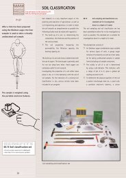
2.7 Manual Drive/Vent Cycles<br />
The <strong>464</strong> <strong>Electronic</strong> <strong>Control</strong> <strong>Unit</strong> can also be operated manually if preferred. It<br />
provides an alternative if the battery power runs out.<br />
To operate the <strong>Control</strong> <strong>Unit</strong> manually, set up and connect the pump, <strong>Control</strong><br />
<strong>Unit</strong> and compressed gas supply (see Section 3.2 Pumping Set Up). Apply the<br />
compressed gas to the <strong>Control</strong> <strong>Unit</strong>.<br />
Use the Regulator on the <strong>Control</strong> <strong>Unit</strong> to decrease or increase the pumping<br />
pressure. To create a drive/vent cycle, use the Manual <strong>Control</strong> Button on the<br />
<strong>Control</strong> Panel. When the Manual <strong>Control</strong> Button is pushed in, it opens the<br />
solenoid, which allows the compressed gas to be applied to the pump. When the<br />
button is released, it allows the unit to vent.<br />
Manual<br />
<strong>Control</strong> Button<br />
Air Out<br />
Air In<br />
Battery<br />
Enclosure<br />
Regulator<br />
Pressure<br />
Gauge<br />
Figure 2-15 <strong>Model</strong> <strong>464</strong> <strong>Control</strong> Panel<br />
2.8 Battery Replacement<br />
Note:<br />
The “Battery<br />
Low!” warning<br />
will appear at<br />
about 0% battery level. This<br />
is a conservative battery level<br />
estimation based on normal<br />
operation.<br />
0<br />
ECU <strong>464</strong> Main Menu<br />
Battery Low!<br />
Preset Please Flow Rates replace or<br />
<strong>User</strong> Flow operate Rates manually<br />
LCD Contrast<br />
OK<br />
About<br />
Figure 2-16 Low Battery Warning<br />
If the battery level is low, the battery warning will be displayed after attempting<br />
to start a drive/vent cycle (Figure 2-16). The battery icon will also be flashing.<br />
Press OK to clear the warning message. It will not be possible to start the vent/<br />
drive cycling with a low battery. Replace the battery or operate the <strong>Control</strong> <strong>Unit</strong><br />
manually using the Manual <strong>Control</strong> Button to continue (see Section 2.7 Manual<br />
Drive/Vent Cycles).<br />
Page 8
<strong>Model</strong> <strong>464</strong> <strong>Electronic</strong> <strong>Control</strong> <strong>Unit</strong> <strong>User</strong> <strong>Guide</strong><br />
Note:<br />
Always follow<br />
local health and<br />
safety practices.<br />
Work safely!<br />
Note:<br />
Keep <strong>Control</strong><br />
<strong>Unit</strong> physically<br />
higher than the<br />
sample discharge<br />
and wellhead.<br />
3.0 Pumping Instructions<br />
3.1 Preparation<br />
• The <strong>Control</strong> <strong>Unit</strong> is shipped without the batteries in the housing.<br />
Install these before operating the unit. The <strong>Control</strong> <strong>Unit</strong> uses four<br />
(4) AA alkaline batteries.<br />
• Do not let water get inside the <strong>Control</strong> <strong>Unit</strong>. Always position the<br />
<strong>Control</strong> <strong>Unit</strong> physically higher than the sample discharge and<br />
wellhead. This helps avoid the siphoning effect, where gravity backflow<br />
of sample water can enter the <strong>Control</strong> <strong>Unit</strong> and cause damage.<br />
• Do not release any pressure from the compressed gas supply until all<br />
preparatory steps are complete.<br />
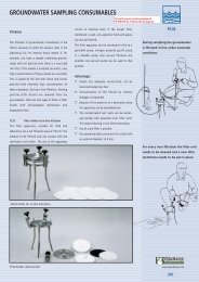
12 Volt<br />
Compressor<br />
Supply<br />
Line<br />
Drive Line<br />
Note:<br />
While the drive/<br />
vent cycles are in<br />
progress it is not<br />
possible to edit the displayed<br />
site information or exit the<br />
site menu when using a<br />
Saved Setting.<br />
Sample<br />
Bottle<br />
Sample<br />
Line<br />
3.2 Pumping Set Up<br />
Quick<br />
Exhaust<br />
Figure 3-1 Pumping Set Up<br />
<strong>464</strong><br />
<strong>Electronic</strong> <strong>Control</strong> <strong>Unit</strong><br />
(125 psi)<br />
Note:<br />
The <strong>Control</strong> <strong>Unit</strong><br />
will turn off after<br />
five minutes of<br />
being idle, provided the <strong>Unit</strong><br />
is not cycling. To turn the<br />
<strong>Unit</strong> off, hold down the OK<br />
button for at least 3 seconds.<br />
1. Connect the Supply Line to the Air In fitting on the <strong>Control</strong> <strong>Unit</strong>. Attach<br />
the other end to the compressed gas supply source.<br />
2. Ensure your pump is installed to the desired pumping depth with the sample<br />
and drive tubing properly connected.<br />
3. Connect the Drive Line from the Air Out fitting to the quick connect on the<br />
wellhead manifold (or air supply connection on a reel).<br />
4. Press any button on the keypad to turn the <strong>Control</strong> <strong>Unit</strong> on.<br />
5. Select the desired pumping settings.<br />
6. Set the compressed gas supply regulator to no more than 150 psi.<br />
7. Start the selected drive/vent cycle.<br />
8. Allow several cycles for water to reach the surface, then adjust the settings<br />
as necessary.<br />
Page 9
<strong>Model</strong> <strong>464</strong> <strong>Electronic</strong> <strong>Control</strong> <strong>Unit</strong> <strong>User</strong> <strong>Guide</strong><br />
3.3 Pump Optimization<br />
Bladder Pumps<br />
• Select and start your desired flow rate from the <strong>User</strong> Flow Rates<br />
menu.<br />
• If higher flow rate is required, stop the drive/vent cycle to allow<br />
editing of the set up. Increase the drive time to increase the flow<br />
rate.<br />
• If increasing the drive time no longer increases the flow rate, increase<br />
the vent time, then re-adjust the drive time to obtain the highest flow<br />
rate.<br />
Double Valve Pumps<br />
• Select and start your desired flow rate from the <strong>User</strong> Flow Rates<br />
menu.<br />
• If a higher flow rate is required, stop the drive/vent cycle to allow<br />
editing of the set up. Slowly increase the drive time to increase the<br />
flow rate.<br />
• If air is expelled, decrease the drive time.<br />
• To further optimize the flow rate, increase or decrease the vent time<br />
until the highest flow rate is achieved.<br />
Once optimization has been done, remember to save the settings for subsequent<br />
sampling events.<br />
Page 10